EP0669243A1 - Diagonal bewegliche Gliederbrücke als Teil eines Übergangs zwischen zwei Fahrzeugen - Google Patents
Diagonal bewegliche Gliederbrücke als Teil eines Übergangs zwischen zwei Fahrzeugen Download PDFInfo
- Publication number
- EP0669243A1 EP0669243A1 EP94102853A EP94102853A EP0669243A1 EP 0669243 A1 EP0669243 A1 EP 0669243A1 EP 94102853 A EP94102853 A EP 94102853A EP 94102853 A EP94102853 A EP 94102853A EP 0669243 A1 EP0669243 A1 EP 0669243A1
- Authority
- EP
- European Patent Office
- Prior art keywords
- link bridge
- vehicles
- guide
- support
- roller
- Prior art date
- Legal status (The legal status is an assumption and is not a legal conclusion. Google has not performed a legal analysis and makes no representation as to the accuracy of the status listed.)
- Granted
Links
Images
Classifications
-
- B—PERFORMING OPERATIONS; TRANSPORTING
- B61—RAILWAYS
- B61D—BODY DETAILS OR KINDS OF RAILWAY VEHICLES
- B61D17/00—Construction details of vehicle bodies
- B61D17/04—Construction details of vehicle bodies with bodies of metal; with composite, e.g. metal and wood body structures
- B61D17/20—Communication passages between coaches; Adaptation of coach ends therefor
- B61D17/22—Communication passages between coaches; Adaptation of coach ends therefor flexible, e.g. bellows
Definitions
- the invention relates to a diagonally movable articulated bridge as part of a transition between two vehicles, the articulated bridge being held movable by the vehicles relative to the latter, and the articulated bridge having two parallel supports for movably receiving the members of the articulated bridge.
- Another advantage of the embodiment according to the invention is that the link bridge no longer has to be uncoupled when two vehicles are uncoupled. This is because the link bridge itself is not permanently connected to the vehicles. At this point it should be mentioned that the link bridge can not slide out of the guide and support elements arranged on the vehicles during operation, since the vehicles themselves are permanently coupled together; the relative movement of the vehicles to one another can be compensated for by an appropriately dimensioned length of the entry of the sectional bridge into the rails.
- the link bridge is held in the uncoupled state on the one hand by the transition itself or by a suspension cable diagonally connecting the front of the vehicle with the link bridge.
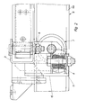
- the support roller is rotatably supported by a fork arranged vertically on the carrier, and the guide roller by a vertical axis on an arm arranged on the carrier.
- the guide roller lies against the web of the U-shaped rail, the support roller rolling on one lower leg of the U-shaped rail.
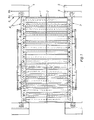
- the link bridge is designated as a whole by 1; the link bridge 1 has the tread members 2 which run parallel to the longitudinal axis of the vehicle and which are movably supported at the ends in supports 3 which are located transversely to the longitudinal axis of the vehicle.
- the vehicles 4, 5 (indicated in FIG. 1) have the U-shaped support and guide rails 6, which likewise run parallel to the longitudinal axis of the vehicle, and serve to hold the support roller 7 and guide roller 8.
- the support roller 7 rolls on the leg 6a of the rail 6, whereas the guide roller 8 is supported on the web 6b of the U-shaped rail 6 (FIG. 1).
- the bridge is guided in that the pair of guide rollers is guided through the two webs 6 b of the two parallel rails 6.
- the carrier 3 has the vertically oriented fork 9 at the end, which rotatably receives the support roller 7.
- the guide roller 8 By the arm 10 also arranged on the carrier 3 is through the vertical axis 11, the guide roller 8 also rotatably mounted.
- the guide roller 8 rolls on the web 6b of the U-shaped rail 6.
Landscapes
- Engineering & Computer Science (AREA)
- Life Sciences & Earth Sciences (AREA)
- Wood Science & Technology (AREA)
- Mechanical Engineering (AREA)
- Platform Screen Doors And Railroad Systems (AREA)
- Handcart (AREA)
- Electric Propulsion And Braking For Vehicles (AREA)
- Train Traffic Observation, Control, And Security (AREA)
- Vehicle Body Suspensions (AREA)
- Bridges Or Land Bridges (AREA)
- Forklifts And Lifting Vehicles (AREA)
- Auxiliary Methods And Devices For Loading And Unloading (AREA)
Abstract
Description
- Diagonal bewegliche Gliederbrücke als Teil eines Übergangs zwischen zwei Fahrzeugen.
- Die Erfindung betrifft eine diagonal bewegliche Gliederbrücke als Teil eines Übergangs zwischen zwei Fahrzeugen, wobei die Gliederbrücke durch die Fahrzeuge relativ zu diesen beweglich gehalten ist, und wobei die Gliederbrücke zwei parallel verlaufende Träger zur beweglichen Aufnahme der Glieder der Gliederbrücke besitzt.
- Eine Gliederbrücke der eingangs genannten ist beispielsweise aus der EP-PS 0 331 121 bekannt. Hierbei besitzt die Gliederbrücke einen Schlitten, der in einem Trog des Fahrzeuges mit einem bestimmten Verstellweg verschieblich gelagert ist. Da der Schlitten in dem Trog gleitend gelagert ist, besteht unter ungünstigen Bedingungen immer die Gefahr, daß der Schlitten in dem Trog verkantet. Hierbei ist dann nicht auszuschließen, daß die Gliederbrücke gestaucht oder überdehnt wird. Darüber hinaus hat sich herausgestellt, daß die bekannte Konstruktion gemäß der EP 0 331 121 aufgrund der aufwendigen Konstruktion bezüglich der Lagerung des Schlittens in dem Trog des Fahrzeuges relativ teuer in der Herstellung ist.
- Der Erfindung liegt daher die Aufgabe zugrunde, eine Gliederbrücke der eingangs genannten Art zu schaffen, die eine einwandfreie Funktionsweise gewährleistet, und die darüber hinaus preiswert in der Herstellung ist.
- Die Aufgabe wird erfindungsgemäß dadurch gelöst, daß der Träger jeweils ein Paar Führungs-und Tragrollen aufweist, wobei die Führungs- und Tragrollen durch an den Fahrzeugen angeordnete Führungs- und Tragelemente aufnehmbar sind. Gegenüber dem Stand der Technik sind bei der erfindungsgemäßen Ausführungsform bei einer Brücke nunmehr nicht mehr zwei Schlitten zur Führung in jeweils einem Trog des Fahrzeugs erforderlich, sondern lediglich nur noch acht Rollen, wobei die Rollen durch zwei Paar U-förmig ausgebildete, an den Fahrzeugen in Richtung der Fahrzeuglängsachse angeordnete die Führungs- und Tragelemente bildenden Schienen geführt und gehalten sind. Durch den Einsatz von Rollen anstelle der zu beiden Seiten der Gliederbrücke angeordneten Schlitten befindet sich die Schwenkachse, bei Höhenversatz der Fahrzeuge relativ zueinander, in der Drehachse der Tragrolle. Im Gegensatz dazu, ist bei dem Stand der Technik gemäß der bereits zuvor abgehandelten europäischen Patentschrift eine gesonderte Schwenkachse vorgesehen. Ein weiterer Vorteil bei der erfindungsgemäßen Ausführungsform besteht darin, daß die Gliederbrücke beim Entkuppeln zweier Fahrzeuge nicht mehr gesondert abgekuppelt werden muß. Dies deshalb, weil die Gliederbrücke selbst nicht fest mit den Fahrzeugen verbunden ist. An dieser Stelle sei erwähnt, daß die Gliederbrücke dennoch nicht im Betrieb aus den an den Fahrzeugen angeordneten Führungs- und Tragelementen herausgleiten kann, da die Fahrzeuge selbst fest miteinander verkuppelt sind; die Relativbewegung der Fahrzeuge zueinander kann durch eine entsprechend dimensionierte Länge des Einlaufs der Gliederbrücke in die Schienen kompensiert werden. Gehalten wird die Gliederbrücke im entkuppelten Zustand zum einen durch den Übergang selbst bzw. durch ein diagonal die Fahrzeugstirnseite mit der Gliederbrücke verbindendes Tragseil.
- Im einzelnen ist vorgesehen, daß die Tragrolle durch eine vertikal am Träger angeordnete Gabel, und die Führungsrolle durch eine vertikale Achse an einem an dem Träger angeordneten Arm drehbar gelagert sind. Hierbei liegt die Führungsrolle an dem Steg der U-förmigen Schiene an, wobei die Tragrolle auf dem einen unteren Schenkel der U-förmigen Schiene abrollt.
- Nach einem weiteren Merkmal der Erfindung sind die Glieder, also sowohl die Trittglieder als auch die Zwischenglieder, der Gliederbrücke in Richtung der Fahrzeuglängsachse durch die Träger aufnehmbar. Eine derartige Konstruktion hat sich dann als sinnvoll herausgestellt, wenn die Gliederbrücke eine größere Breite als Länge besitzt. Dies deshalb, weil eine derart aufgebaute Gliederbrücke eine geringere Durchbiegung aufweist, als dies bei einer Gliederbrücke der Fall ist, deren Glieder quer zur Längsrichtung des Fahrzeugs durch Träger gehalten sind.
- Anhand der Zeichnung wird nachstehend die Erfindung beispielhaft näher erläutert.
- Fig. 1 zeigt die Gliederbrücke in einer Draufsicht;
- Fig. 2 zeigt die Einzelheit X in vergrößerter Darstellung in einer Seitenansicht.
- Gemäß Fig. 1 ist die Gliederbrücke insgesamt mit 1 bezeichnet; die Gliederbrücke 1 besitzt die parallel zur Fahrzeuglängsachse verlaufenden Trittglieder 2, die endseitig in Trägern 3 beweglich gelagert sind, die sich quer zur Fahrzeugslängsachse befinden. Die Fahrzeuge 4, 5 (in Fig. 1 angedeutet) besitzen die U-förmig ausgebildeten Trag- und Führungsschienen 6, die ebenfalls parallel zur Fahrzeuglängsachse verlaufen, und der Aufnahme der Tragrolle 7 und Führungsrolle 8 dienen. Die Tragrolle 7 rollt hierbei auf den Schenkel 6a der Schiene 6 ab, wohingegen die Führungsrolle 8 sich an dem Steg 6b der U-förmig ausgebildeten Schiene 6 abstützt (Fig. 1). Geführt wird die Brücke dadurch, daß das Führungsrollenpaar durch die beiden Stege 6 b der beiden parallel verlaufenden Schienen 6 geführt wird.
- Wie aus Fig. 2 erkennbar, besitzt der Träger 3 endseitig die vertikal ausgerichtete Gabel 9, die die Tragrolle 7 drehbar aufnimmt. Durch den ebenfalls am Träger 3 angeordneten Arm 10 ist durch die vertikale Achse 11 die Führungsrolle 8 ebenfalls drehbar gelagert. Die Führungsrolle 8 rollt hierbei an dem Steg 6b der U-förmig ausgebildeten Schiene 6 ab.
Claims (7)
dadurch gekennzeichnet, daß
der Träger (3) jeweils ein Paar Führungs- und Tragrollen (8,7) aufweist, wobei die Führungs-und Tragrollen (8,7) durch an den Fahrzeugen angeordneten Führungs- und Tragelementen (6) aufnehmbar sind.
dadurch gekennzeichnet, daß
das Führungs- und Tragelement eine U-förmig ausgebildete, an dem Fahrzeug in Fahrzeugslängsrichtung angeordnete Schiene (6) ist.
dadurch gekennzeichnet, daß
die Tragrolle (7) durch eine vertikal am Träger (3) angeordnete Gabel (9) drehbar gelagert ist.
dadurch gekennzeichnet, daß
die Führungsrolle (8) durch eine vertikale Achse (11) an einem am Träger (3) angeordneten Arm (10) drehbar gelagert ist.
dadurch gekennzeichnet, daß
die Führungsrolle (8) an dem Steg (6b) der U-förmigen Schiene (6) anliegt, und die Tragrolle (7) auf dem einen Schenkel (6a) der U-förmigen Schiene (6) abrollt.
dadurch gekennzeichnet, daß
der Übergang von den Fahrzeugen (4,5) trennbar ist.
dadurch gekennzeichnet, daß
die Glieder (2) der Gliederbrücke (1) in Richtung der Fahrzeuglängsachse durch die Träger (3) aufnehmbar sind.
Priority Applications (7)
| Application Number | Priority Date | Filing Date | Title |
|---|---|---|---|
| EP94102853A EP0669243B1 (de) | 1994-02-25 | 1994-02-25 | Diagonal bewegliche Gliederbrücke als Teil eines Übergangs zwischen zwei Fahrzeugen |
| DE59403645T DE59403645D1 (de) | 1994-02-25 | 1994-02-25 | Diagonal bewegliche Gliederbrücke als Teil eines Übergangs zwischen zwei Fahrzeugen |
| AT94102853T ATE156436T1 (de) | 1994-02-25 | 1994-02-25 | Diagonal bewegliche gliederbrücke als teil eines übergangs zwischen zwei fahrzeugen |
| ES94102853T ES2107699T3 (es) | 1994-02-25 | 1994-02-25 | Pasarela articulada, en diagonal, movil, como parte de una intercomunicacion entre dos vehiculos. |
| US08/323,759 US5471935A (en) | 1994-02-25 | 1994-10-17 | Linking platform |
| CN94113362A CN1058237C (zh) | 1994-02-25 | 1994-12-15 | 作为两车之间过渡装置的可斜对角活动的链式桥 |
| JP7061457A JP3060367B2 (ja) | 1994-02-25 | 1995-02-14 | 2つの車両間の移行部としてのリンクブリツジ |
Applications Claiming Priority (1)
| Application Number | Priority Date | Filing Date | Title |
|---|---|---|---|
| EP94102853A EP0669243B1 (de) | 1994-02-25 | 1994-02-25 | Diagonal bewegliche Gliederbrücke als Teil eines Übergangs zwischen zwei Fahrzeugen |
Publications (2)
| Publication Number | Publication Date |
|---|---|
| EP0669243A1 true EP0669243A1 (de) | 1995-08-30 |
| EP0669243B1 EP0669243B1 (de) | 1997-08-06 |
Family
ID=8215725
Family Applications (1)
| Application Number | Title | Priority Date | Filing Date |
|---|---|---|---|
| EP94102853A Expired - Lifetime EP0669243B1 (de) | 1994-02-25 | 1994-02-25 | Diagonal bewegliche Gliederbrücke als Teil eines Übergangs zwischen zwei Fahrzeugen |
Country Status (7)
| Country | Link |
|---|---|
| US (1) | US5471935A (de) |
| EP (1) | EP0669243B1 (de) |
| JP (1) | JP3060367B2 (de) |
| CN (1) | CN1058237C (de) |
| AT (1) | ATE156436T1 (de) |
| DE (1) | DE59403645D1 (de) |
| ES (1) | ES2107699T3 (de) |
Cited By (2)
| Publication number | Priority date | Publication date | Assignee | Title |
|---|---|---|---|---|
| CN102476641A (zh) * | 2010-11-26 | 2012-05-30 | 许布奈有限公司 | 两个彼此铰接的车辆之间的过渡部的过道 |
| EP3992051A1 (de) | 2020-10-29 | 2022-05-04 | Dellner Couplers AB | Riffelblech für einen fussboden einer gangway sowie gangway |
Families Citing this family (12)
| Publication number | Priority date | Publication date | Assignee | Title |
|---|---|---|---|---|
| FR2724620B1 (fr) * | 1994-09-16 | 1997-01-10 | Lohr Ind | Passerelle deformable entre deux plans de chargement portes par des chassis successifs notamment ferroviaires |
| US5979310A (en) * | 1996-11-18 | 1999-11-09 | Pitney Bowes Inc. | Apparatus and method for printing images |
| JP3962463B2 (ja) * | 1997-11-28 | 2007-08-22 | 株式会社成田製作所 | 車両用連結幌 |
| AT503047B1 (de) * | 2003-10-31 | 2007-09-15 | Siemens Transportation Systems | Zugverband mit zumindest zwei miteinander gekuppelten schienenfahrzeugen |
| DE102004011865A1 (de) * | 2004-03-11 | 2005-09-29 | Hübner GmbH | Übergangsbrücke eines Übergangs mit einem Balg zwischen zwei durch ein Gelenk miteinander verbundener Fahrzeuge |
| JP4417821B2 (ja) | 2004-11-22 | 2010-02-17 | 株式会社日立製作所 | 貫通路を備える鉄道車両 |
| DE102005053207A1 (de) | 2005-11-08 | 2007-05-10 | Hübner GmbH | Boden eines Übergangs zwischen zwei gelenkig miteinander verbundenen Fahrzeugen |
| DE102005062142B3 (de) * | 2005-12-22 | 2007-08-02 | Hübner Transportation GmbH | Ausstellbare Trittstufe eines Fahrzeuges |
| DE502009000605D1 (de) * | 2009-06-08 | 2011-06-09 | Huebner Gmbh | Gliederbrücke eines Übergangs zwischen zwei gelenkig miteinander gekuppelten Fahrzeugen |
| DK2399798T3 (da) | 2010-06-25 | 2012-09-10 | Huebner Gmbh | Overgang mellem to fartøjer, f.eks. skinnefartøjer, der er forbundet med hinanden ved hjælp af et led, med en bro og en bælg |
| US9550079B2 (en) * | 2011-12-13 | 2017-01-24 | Theresa H. D'Angelo | Multilevel railcar safety catch system |
| ES2524142T3 (es) | 2012-08-22 | 2014-12-04 | HÜBNER GmbH & Co. KG | Pasarela o paso con un puente y un fuelle giratorio o rotativo en forma de túnel entre dos vehículos unidos por medio de una conexión articulada |
Citations (1)
| Publication number | Priority date | Publication date | Assignee | Title |
|---|---|---|---|---|
| EP0493818A1 (de) * | 1990-12-29 | 1992-07-08 | HÜBNER Gummi- und Kunststoff GmbH | Übergangsbrücke für Schienenfahrzeuge |
Family Cites Families (12)
| Publication number | Priority date | Publication date | Assignee | Title |
|---|---|---|---|---|
| US445897A (en) * | 1891-02-03 | Safety-guard for cars | ||
| US68543A (en) * | 1867-09-03 | Improved safety oak-platform | ||
| US686797A (en) * | 1901-05-20 | 1901-11-19 | Frank B Anderson | Tramway for street-cars. |
| US714312A (en) * | 1902-04-29 | 1902-11-25 | Robinson Max | Safety attachment for cars. |
| DE539581C (de) * | 1930-08-08 | 1931-11-30 | Philipp Kremer Dr Ing | UEbergangsplattform fuer Wagen mit verschiebbaren Staeben |
| BE460037A (de) * | 1939-06-29 | |||
| JPS5533372Y2 (de) * | 1973-08-20 | 1980-08-08 | ||
| DE3628627A1 (de) * | 1986-08-22 | 1988-02-25 | Linke Hofmann Busch | Uebergangsbruecke fuer eine uebergangseinrichtung |
| DE3806702A1 (de) * | 1988-03-02 | 1989-09-14 | Huebner Gummi & Kunststoff | Gliederbruecke als teil eines trennbaren wagenueberganges |
| DE3839716A1 (de) * | 1988-11-24 | 1990-05-31 | Huebner Gummi & Kunststoff | Stirnseite eines eisenbahnreisezugwagens |
| ES2077946T3 (es) * | 1992-08-08 | 1995-12-01 | Huebner Gummi & Kunststoff | Puente articulado de una intercomunicacion separable entre vehiculos articulados acoplados entre si. |
| US5267514A (en) * | 1992-10-28 | 1993-12-07 | Bae Automated Systems, Inc. | Track for material handling car and car wheel assembly for cooperation therewith |
-
1994
- 1994-02-25 AT AT94102853T patent/ATE156436T1/de not_active IP Right Cessation
- 1994-02-25 DE DE59403645T patent/DE59403645D1/de not_active Expired - Lifetime
- 1994-02-25 ES ES94102853T patent/ES2107699T3/es not_active Expired - Lifetime
- 1994-02-25 EP EP94102853A patent/EP0669243B1/de not_active Expired - Lifetime
- 1994-10-17 US US08/323,759 patent/US5471935A/en not_active Expired - Lifetime
- 1994-12-15 CN CN94113362A patent/CN1058237C/zh not_active Expired - Fee Related
-
1995
- 1995-02-14 JP JP7061457A patent/JP3060367B2/ja not_active Expired - Lifetime
Patent Citations (1)
| Publication number | Priority date | Publication date | Assignee | Title |
|---|---|---|---|---|
| EP0493818A1 (de) * | 1990-12-29 | 1992-07-08 | HÜBNER Gummi- und Kunststoff GmbH | Übergangsbrücke für Schienenfahrzeuge |
Cited By (3)
| Publication number | Priority date | Publication date | Assignee | Title |
|---|---|---|---|---|
| CN102476641A (zh) * | 2010-11-26 | 2012-05-30 | 许布奈有限公司 | 两个彼此铰接的车辆之间的过渡部的过道 |
| CN102476641B (zh) * | 2010-11-26 | 2014-09-10 | 许布奈有限公司 | 两个彼此铰接的车辆之间的过渡部的过道 |
| EP3992051A1 (de) | 2020-10-29 | 2022-05-04 | Dellner Couplers AB | Riffelblech für einen fussboden einer gangway sowie gangway |
Also Published As
| Publication number | Publication date |
|---|---|
| ATE156436T1 (de) | 1997-08-15 |
| CN1058237C (zh) | 2000-11-08 |
| JP3060367B2 (ja) | 2000-07-10 |
| CN1116171A (zh) | 1996-02-07 |
| US5471935A (en) | 1995-12-05 |
| EP0669243B1 (de) | 1997-08-06 |
| ES2107699T3 (es) | 1997-12-01 |
| JPH07257372A (ja) | 1995-10-09 |
| DE59403645D1 (de) | 1997-09-11 |
Similar Documents
| Publication | Publication Date | Title |
|---|---|---|
| EP0669243B1 (de) | Diagonal bewegliche Gliederbrücke als Teil eines Übergangs zwischen zwei Fahrzeugen | |
| EP1345731A1 (de) | Gliederschürze zur abdeckung von maschinenteilen | |
| EP1243461B1 (de) | Sitzuntergestell für einen Fahrzeugsitz | |
| WO1998052822A1 (de) | Schleppfahrzeug für flugzeuge | |
| DE2711994C3 (de) | Fahrzeug, das gegenüber einem Fahrweg mit Hilfe einer anziehenden magnetischen Einrichtung und einer Zusatzkrafteinrichtung gehalten wird | |
| EP0359962A1 (de) | Sitz, insbesondere Kraftfahrzeugsitz | |
| AT400337B (de) | Gleisstopfmaschine mit in gleisquerrichtung verstellbaren stopfeinheiten | |
| EP1805048A1 (de) | Führungsvorrichtung für ein bewegbares dachelement eines öffnungsfähigen fahrzeugdaches | |
| DE3628627C2 (de) | ||
| WO2001072178A1 (de) | Vorrichtung für eine verstellung von komponenten eines stuhls | |
| EP0857522B1 (de) | Walzstrasse | |
| DE2843254C2 (de) | Gleitführung für längs verschiebbare Fahrzeugsitze | |
| WO2020178264A1 (de) | Längseinstellvorrichtung zur motorischen längseinstellung eines fahrzeugsitzes sowie fahrzeugsitz | |
| EP0311958A1 (de) | Weichenanordnung | |
| DE19519153A1 (de) | Führung für verstellbare Fahrzeugsitze | |
| DE3540040C2 (de) | ||
| EP0702126B1 (de) | Rolladen | |
| EP0153573B1 (de) | Schiebeweiche | |
| DE10034008B4 (de) | Einrichtung zur Verstellung und Arretierung eines in Längsrichtung verschiebbaren Sitzes | |
| DE7306144U (de) | Verstellvorrichtung fuer fahrzeugsitze | |
| DE10065130A1 (de) | Windschild für Motorräder | |
| EP0071860B1 (de) | Abstellvorrichtung für Kraftfahrzeuge | |
| EP3231975A1 (de) | Schiebetürführung für ein kraftfahrzeug | |
| EP3789808B1 (de) | Kopplungsglied für eine positioniereinrichtung sowie positioniereinrichtung mit einem kopplungsglied | |
| DE2942670C2 (de) | Fräswalzenhalterung für Fräsmaschinen zum Abfräsen von Straßendecken |
Legal Events
| Date | Code | Title | Description |
|---|---|---|---|
| PUAI | Public reference made under article 153(3) epc to a published international application that has entered the european phase |
Free format text: ORIGINAL CODE: 0009012 |
|
| 17P | Request for examination filed |
Effective date: 19940822 |
|
| AK | Designated contracting states |
Kind code of ref document: A1 Designated state(s): AT BE CH DE DK ES FR GB GR IE IT LI LU NL PT SE |
|
| 17Q | First examination report despatched |
Effective date: 19960220 |
|
| GRAG | Despatch of communication of intention to grant |
Free format text: ORIGINAL CODE: EPIDOS AGRA |
|
| GRAH | Despatch of communication of intention to grant a patent |
Free format text: ORIGINAL CODE: EPIDOS IGRA |
|
| GRAH | Despatch of communication of intention to grant a patent |
Free format text: ORIGINAL CODE: EPIDOS IGRA |
|
| GRAA | (expected) grant |
Free format text: ORIGINAL CODE: 0009210 |
|
| AK | Designated contracting states |
Kind code of ref document: B1 Designated state(s): AT BE CH DE DK ES FR GB GR IE IT LI LU NL PT SE |
|
| PG25 | Lapsed in a contracting state [announced via postgrant information from national office to epo] |
Ref country code: NL Free format text: LAPSE BECAUSE OF FAILURE TO SUBMIT A TRANSLATION OF THE DESCRIPTION OR TO PAY THE FEE WITHIN THE PRESCRIBED TIME-LIMIT Effective date: 19970806 Ref country code: GR Free format text: LAPSE BECAUSE OF FAILURE TO SUBMIT A TRANSLATION OF THE DESCRIPTION OR TO PAY THE FEE WITHIN THE PRESCRIBED TIME-LIMIT Effective date: 19970806 Ref country code: DK Free format text: LAPSE BECAUSE OF NON-PAYMENT OF DUE FEES Effective date: 19970806 |
|
| REF | Corresponds to: |
Ref document number: 156436 Country of ref document: AT Date of ref document: 19970815 Kind code of ref document: T |
|
| REG | Reference to a national code |
Ref country code: CH Ref legal event code: EP |
|
| GBT | Gb: translation of ep patent filed (gb section 77(6)(a)/1977) |
Effective date: 19970808 |
|
| REF | Corresponds to: |
Ref document number: 59403645 Country of ref document: DE Date of ref document: 19970911 |
|
| ET | Fr: translation filed | ||
| ITF | It: translation for a ep patent filed |
Owner name: STUDIO JAUMANN P. & C. S.N.C. |
|
| PG25 | Lapsed in a contracting state [announced via postgrant information from national office to epo] |
Ref country code: SE Effective date: 19971106 |
|
| PG25 | Lapsed in a contracting state [announced via postgrant information from national office to epo] |
Ref country code: PT Effective date: 19971112 |
|
| REG | Reference to a national code |
Ref country code: ES Ref legal event code: FG2A Ref document number: 2107699 Country of ref document: ES Kind code of ref document: T3 |
|
| NLV1 | Nl: lapsed or annulled due to failure to fulfill the requirements of art. 29p and 29m of the patents act | ||
| PG25 | Lapsed in a contracting state [announced via postgrant information from national office to epo] |
Ref country code: LU Free format text: LAPSE BECAUSE OF NON-PAYMENT OF DUE FEES Effective date: 19980225 Ref country code: AT Free format text: LAPSE BECAUSE OF NON-PAYMENT OF DUE FEES Effective date: 19980225 |
|
| PG25 | Lapsed in a contracting state [announced via postgrant information from national office to epo] |
Ref country code: LI Free format text: LAPSE BECAUSE OF NON-PAYMENT OF DUE FEES Effective date: 19980228 Ref country code: CH Free format text: LAPSE BECAUSE OF NON-PAYMENT OF DUE FEES Effective date: 19980228 Ref country code: BE Free format text: LAPSE BECAUSE OF NON-PAYMENT OF DUE FEES Effective date: 19980228 |
|
| PG25 | Lapsed in a contracting state [announced via postgrant information from national office to epo] |
Ref country code: IE Free format text: LAPSE BECAUSE OF NON-PAYMENT OF DUE FEES Effective date: 19980605 |
|
| PLBE | No opposition filed within time limit |
Free format text: ORIGINAL CODE: 0009261 |
|
| STAA | Information on the status of an ep patent application or granted ep patent |
Free format text: STATUS: NO OPPOSITION FILED WITHIN TIME LIMIT |
|
| REG | Reference to a national code |
Ref country code: IE Ref legal event code: FD4D Ref document number: 75620 Country of ref document: IE |
|
| 26N | No opposition filed | ||
| BERE | Be: lapsed |
Owner name: HUBNER GUMMI- UND KUNSTSTOFF G.M.B.H. Effective date: 19980228 |
|
| REG | Reference to a national code |
Ref country code: CH Ref legal event code: PL |
|
| REG | Reference to a national code |
Ref country code: GB Ref legal event code: IF02 |
|
| PGFP | Annual fee paid to national office [announced via postgrant information from national office to epo] |
Ref country code: FR Payment date: 20120227 Year of fee payment: 19 |
|
| PGFP | Annual fee paid to national office [announced via postgrant information from national office to epo] |
Ref country code: DE Payment date: 20120126 Year of fee payment: 19 |
|
| PGFP | Annual fee paid to national office [announced via postgrant information from national office to epo] |
Ref country code: GB Payment date: 20120221 Year of fee payment: 19 Ref country code: IT Payment date: 20120224 Year of fee payment: 19 |
|
| PGFP | Annual fee paid to national office [announced via postgrant information from national office to epo] |
Ref country code: ES Payment date: 20120224 Year of fee payment: 19 |
|
| GBPC | Gb: european patent ceased through non-payment of renewal fee |
Effective date: 20130225 |
|
| REG | Reference to a national code |
Ref country code: FR Ref legal event code: ST Effective date: 20131031 |
|
| REG | Reference to a national code |
Ref country code: DE Ref legal event code: R119 Ref document number: 59403645 Country of ref document: DE Effective date: 20130903 |
|
| PG25 | Lapsed in a contracting state [announced via postgrant information from national office to epo] |
Ref country code: IT Free format text: LAPSE BECAUSE OF NON-PAYMENT OF DUE FEES Effective date: 20130225 |
|
| PG25 | Lapsed in a contracting state [announced via postgrant information from national office to epo] |
Ref country code: GB Free format text: LAPSE BECAUSE OF NON-PAYMENT OF DUE FEES Effective date: 20130225 Ref country code: FR Free format text: LAPSE BECAUSE OF NON-PAYMENT OF DUE FEES Effective date: 20130228 Ref country code: DE Free format text: LAPSE BECAUSE OF NON-PAYMENT OF DUE FEES Effective date: 20130903 |
|
| REG | Reference to a national code |
Ref country code: ES Ref legal event code: FD2A Effective date: 20140408 |
|
| PG25 | Lapsed in a contracting state [announced via postgrant information from national office to epo] |
Ref country code: ES Free format text: LAPSE BECAUSE OF NON-PAYMENT OF DUE FEES Effective date: 20130226 |