EP0659108B1 - Walzenpressen, insbesondere zum zerkleinern von stark abrasiven stoffen - Google Patents
Walzenpressen, insbesondere zum zerkleinern von stark abrasiven stoffen Download PDFInfo
- Publication number
- EP0659108B1 EP0659108B1 EP94925371A EP94925371A EP0659108B1 EP 0659108 B1 EP0659108 B1 EP 0659108B1 EP 94925371 A EP94925371 A EP 94925371A EP 94925371 A EP94925371 A EP 94925371A EP 0659108 B1 EP0659108 B1 EP 0659108B1
- Authority
- EP
- European Patent Office
- Prior art keywords
- wear
- roll
- press according
- zones
- spaces
- Prior art date
- Legal status (The legal status is an assumption and is not a legal conclusion. Google has not performed a legal analysis and makes no representation as to the accuracy of the status listed.)
- Expired - Lifetime
Links
Images

Classifications
-
- B—PERFORMING OPERATIONS; TRANSPORTING
- B02—CRUSHING, PULVERISING, OR DISINTEGRATING; PREPARATORY TREATMENT OF GRAIN FOR MILLING
- B02C—CRUSHING, PULVERISING, OR DISINTEGRATING IN GENERAL; MILLING GRAIN
- B02C4/00—Crushing or disintegrating by roller mills
- B02C4/28—Details
- B02C4/30—Shape or construction of rollers
- B02C4/305—Wear resistant rollers
-
- Y—GENERAL TAGGING OF NEW TECHNOLOGICAL DEVELOPMENTS; GENERAL TAGGING OF CROSS-SECTIONAL TECHNOLOGIES SPANNING OVER SEVERAL SECTIONS OF THE IPC; TECHNICAL SUBJECTS COVERED BY FORMER USPC CROSS-REFERENCE ART COLLECTIONS [XRACs] AND DIGESTS
- Y10—TECHNICAL SUBJECTS COVERED BY FORMER USPC
- Y10T—TECHNICAL SUBJECTS COVERED BY FORMER US CLASSIFICATION
- Y10T29/00—Metal working
- Y10T29/49—Method of mechanical manufacture
- Y10T29/49544—Roller making
- Y10T29/4956—Fabricating and shaping roller work contacting surface element
- Y10T29/49563—Fabricating and shaping roller work contacting surface element with coating or casting about a core
Definitions
- the invention relates to a roller press, in particular for crushing strongly abrasive substances, with at least two press rolls, each arranged on a base body Have wear layer, the wear layer essentially flat zones from a highly wear-resistant Has material and the spaces between the highly wear-resistant zones with a material of different wear resistance are filled out.
- Roller presses are widely used in technology found, their uses are essentially in divide three groups of briquetting, compacting and shredding to let. In all three applications, the press rollers practice a more or less strong one on the materials to be processed Pressure load. Depending on the profile of the press rolls in addition to this compressive stress, there is also a sliding stress on the roller surface. The intensity depends the sliding load essentially depends on the amount of pressure applied on the rollers, the profiling of the roller surface and the properties of the substances to be processed. This stress can be on the rollers, especially at high Pressing forces, cause heavy wear.
- a generic roller press in particular a grinding roller, is known from EP-A-0516952.
- There is a roller press described in the numerous blind holes in the peripheral area are arranged in the pin-shaped material pieces are plugged in.
- the main part of each pen-shaped The piece of material is in the roller body while the rest of it sticks out.
- the spaces between the hedgehog-shaped pin-shaped material pieces protruding from the roller base body can be made with a ceramic plastic Material.
- the wear-resistant pieces of material usually wear more slowly than the material in the gaps, a profiled is formed during operation Roller surface.
- the advantage is better pull-in capacity and thus achieving a higher throughput.
- the Manufacture of such known roller presses is however through the introduction of the numerous anchoring blind holes in the Roller body very time-consuming and therefore with associated with high costs. Furthermore, this solution is There is a very high risk of pins breaking out.
- a roller is known in which in the Longitudinal grooves between, preferably consisting of the roll base material Webs introduced a wear-resistant material is so that it becomes a wear profiling in later operation the surface is coming.
- DE-A-2133300 is a hot isostatic Press-produced wear layer for a press roll known as a closed outer layer on a carrier material is applied.
- roller press of the type mentioned that provide a high Has a service life and for all applications (briquetting, Compacting and shredding) usable and easy to manufacture is.
- the object of the present invention is achieved in that the intermediate material is a sinterable composite material is and the highly wear-resistant zones from hot isostatic Pressed hard body are formed, the Intermediate material and the material of the wear-resistant Zones through a hot isostatic pressing process on the base body are attached and the wear resistance of the intermediate material according to a desired, due to wear adjusting profiling essentially slightly is higher or lower than the wear resistance of the hard body.
- the wear layer according to the invention a powder metallurgical hard layer, the flat one Zones and filled spaces with different ones Has wear properties. This turns into one profiling on the roller surface after a certain period of use a, which the desired better indentation of the to be processed Material. Since it is the zone material and the composite material in each case by powder metallurgy materials to be produced are hot isostatic Presses attachable to the roller body. Of the hot isostatic pressing process ensures that the entire wear layer has a connection to the roller body, which is so firm that not individual components the wear layer can be removed from this can. Although powder metallurgical hard layers that are caused by hot isostatic pressing are manufactured in the state of the Technology known.
- the solution according to the invention is as it were for briquetting, Compacting and crushing highly abrasive Suitable materials, whereby the service life is significantly increased.
- the wear layer can easily press any desired Be given shape. Furthermore, such Wear layer can be produced in one operation, which is why yourself the time and cost of making one Have the roller press reduced.
- the is adapted to a specific substance to be processed can the ratio of the wear resistance of the composite and the wear resistance of the hard body to each processing, abrasive material. That poses especially in the production of such a wear layer not a noteworthy problem because the powder metallurgical Materials in terms of their composition coordinated according to the application can be.
- the overall level of Wear resistance of the two materials raised or be lowered.
- the hard bodies are preferred on their composite material embedded scope at least in some areas with the Composite material bonded. Such Connection can by the hot isostatic pressing process can inevitably be achieved and is therefore very simple executable.
- the hard body and the space material have one at their contact points Diffusion area leading to very strong adherence leads the two materials together.
- Optimal profiling can be achieved in the operation of the roller press achieved in that the area of the hard body is about 60% to 90% of the total area of the active wear layer.
- the area of the Understand the wear layer on the Processing process of the abrasive substances takes part.
- the highly wear-resistant zones are especially then easy to manufacture if the hard body is platelet-shaped are trained.
- Such platelet-shaped hard bodies can e.g. applied in advance on the roller body and then the spaces are filled with composite material.
- the shape of the platelet-shaped hard body can be arbitrary fail.
- the wear layer is reached when the hard body material and the space material has a carbide content of up to Have 65%.
- the profiling is further improved if the size of the area of a wear-resistant zone is approximately 1 to 20 cm 2 .
- the service life can continue to be considerable be increased if the wear layer is ceramic Has components.
- the wear layer preferably has a very fine-grained one Structure, which gives greater strength, hardness, Toughness and impact energy is achieved.
- the Wear layer on the entire surface of the Working area of the press roll applied flat Prefers will also be a version in which the wear layer between the work area, circumferential webs is arranged, which is radial to Extend the roller base outwards. This is the Hard layer on its edge by means of the webs surround formed, which prevents the lateral edges of the hard layer by impact and Break out edge load.
- a further embodiment suggests that in the Outer jacket of the roller body in the work area of Press roll several substantially evenly around the circumference distributed, pocket-shaped depressions are introduced, in which each have the wear layer recorded. At Such an embodiment can, depending on the application corresponding size and area distribution of the Wear layer on the roller circumference can be reached.
- the press roll can have a profiled surface, preferably have a briquette profile.
- the Wear layer especially stops the sliding movements the surface of the individual briquette profiles in the press roll stood, whereby a during a significant service life desired shape tolerance can be provided.
- a further embodiment can be used in a favorable manner the roller base body is essentially cylindrical
- Have recording area on the circumference of several powder metallurgical wear layer on the outside load-bearing basic body segments are arranged detachably. This makes the wear layer particularly easy produce even with relatively large press roll diameters.
- Form preferred here the basic body segments around the recording area a closed ring.
- the wear layer applied on a closed bandage the form or is frictionally arranged on the roller body.
- the hard layer can also relatively little effort on the roller base to be ordered.
- Material, especially a ductile material the webs the formation of cracks due to shrinkage stresses be avoided.
- the method offers the advantage of only changing some process or material parameters Manufacture wear layer that is very different Has wear properties. Because of this, can e.g. the wear layer of a press roll in your Wear behavior of the abrasive material to be processed be adjusted.
- the highly wear-resistant material before application to the Base part through a hot isostatic pressing process Hard bodies are made.
- the hard body can thus get any shape and according to the later desired profile applied to the base part will.
- the hot isostatic pressing process can be controlled that the wear resistance of the Hard body and the wear resistance of the gaps filling composites only slightly apart deviate, the wear resistance of the hard body depending according to the desired, resulting from wear Profiling is higher or lower than that Wear resistance of the space material. Since the Wear resistance only slightly apart deviate, it is ensured that the entire Wear resistance of the wear layer is relatively high, there is still a profiling to improve the feeder of the abrasive material to be processed.
- the wear resistance can be affected by the respective supplied hard phase content in the hard body material or adjusted accordingly in the composite material will.
- the selected powder metallurgical materials can the wear behavior of the zones and the filled Spaces are set, which also changes overall wear behavior of the wear layer changes.
- Fig. 1 shows a press roll 1, the same with one constructed press roll for use in a roll press for Press compacting or for crushing highly abrasive Fabrics is provided.
- the press roll 1 consists in essentially from a cylindrical roller body 2 the bearing pin 3 arranged coaxially on both sides are provided.
- the press roll 1 has wear protection a arranged on the base body 2, powder metallurgical Wear layer 4 on by hot isostatic pressing is made.
- the wear layer consists of zones 5, made of a highly wear-resistant material and a die Gaps 6 of the zones 5 filling wear-resistant Composite. The wear behavior of zones 5 and the gaps 6 is due to the property of processing, abrasive material.
- Zones 5 and the gaps 6 have different features Wear behavior on, which affects the operation of the Roll press a surface profiling of the press rolls 1 sets.
- the zones 5 are by hard body 7 (see Fig. 3) formed by hot isostatic pressing are.
- the wear resistance of such hard body 7 is through the process of hot isostatic pressing and Material composition of the powder metallurgical substance certainly.
- the hard body 7 extend to the Circumference of the roller body 2.
- the spaces 6 are thereby, as already mentioned, by a composite material filled out, its wear properties also by a hot isostatic pressing process and through the powder metallurgical material composition of the Composite is determined.
- the composite and the hard body 7 are together on the base body 2 attached a hot isostatic pressing process.
- the Powder metallurgical wear layer 4 accordingly has one Wear behavior based on the properties of the processing substance is adapted. This is preferred as a starting product for the production of the wear layer 4, highly wear-resistant powder metallurgical materials used, e.g. also contain ceramic components can. Furthermore, the carbide content of the Hard body material and the gap material up to Amount to 65%.
- the area of the highly wear-resistant zones 5 usually takes up approximately 60 to 90% of the total area of the active wear layer 4.
- the size of the area of a wear-resistant zone 5 is usually 1 to 20 cm 2 .
- a press roll 1 is shown on the Outer circumference of the roller base body 2 all around closed bandage 8 is arranged, the form or is frictionally attached to the roller body 2.
- On the wear layer 4 is the outer surface of the bandage 8 upset. The fact that the bandage 8 as a carrier medium for the wear layer 4 is used, the Wear layer easier on the roller body 2 apply.
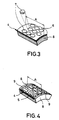
- FIG. 8 A section of the bandage 8 is shown in FIG whose outside the wear layer 4 over the entire working area A of the wear roller 1 extends.
- the plate-like ones are formed Hard body 7, which in this embodiment Show hexagon shape, very easy to recognize.
- the shape of the Hard body 7 can, however, turn out arbitrarily and accordingly the conditions of use.
- FIG. 4 A second variant of a bandage 8 is shown in FIG. 4, where the wear layer between the work area A laterally bounding, circumferential webs 9 is arranged.
- the webs 9 extend radially to the roller base body 2 outwards and have a height that is approximately the thickness of the Wear layer 4 corresponds. Through the webs 9 is the Wear layer 4 completely bordered on the side, creating a Breaking out of the pages due to excessive pressure in the Edge area can occur.
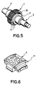
- Fig. 5 shows a third variant of a press roll for Use in a roller press of the present invention whose roller base body 2 is a substantially cylindrical Receiving area 10, on the circumference of several Wear layer 4 on the outside supporting body segments 11 are arranged releasably.
- the basic body segments 11 are form-fitting on the receiving area 10 of the Roller base body 2 placed.
- the shape Base body segments 11 around the receiving area 10 closed ring.
- the segments 11 are by means of Fasteners and the type of tongue and groove connections (see Fig. 6) connected together so that a closed roller surface on the outside is formed.
- the wear layer 4 according to one of the variants of FIG. 3 and 4 can be arranged.
- the method for producing the wear layer 4 is characterized in that first highly wear-resistant material on the roller base 2 is applied so that essentially flat, evenly distributed zones 5 are formed. Next the spaces 6 of the flat zones 5 are filled with a wear-resistant composite material. Of the Zone material and the space material are subsequently on the roller body 2 by a hot isostatic pressing process attached. There are now two Process variants, such as hard body 7 forming zones 5 be produced by a hot isostatic pressing process can.
- the highly wear-resistant becomes Material before application to the roller base 2 Hard body 7 by a hot isostatic pressing process produced. Accordingly, the so generated platelet-shaped hard body 7 on the roller base body 2 in any arrangement and in any own form are applied and the spaces 6 subsequently be filled with a wear-resistant composite. In the subsequent hot isostatic pressing process the composite material in the spaces 6 compressed accordingly and the entire wear layer 4 attached to the roller base body 2.
- the hard bodies 7 from the highly wear-resistant material through the hot isostatic pressing process for attaching the Zone material are manufactured.
- the in particular to produce a wear layer 4 suitable on a base body segment 11 a shape be provided in accordance with the desired Composition of selected powder metallurgical materials be filled in. The shape then positions the corresponding zone material and interspace material the base part.
- the hard body 7 is pressed at the same time manufactured, the composite material in the spaces 6 compacted and the entire wear layer 4 on the base part attached.
- the hot isostatic pressing process can be controlled that the wear resistance of the Hard body 7 and the wear resistance of the Interstices 6 filling composite material only slightly differ from each other. Something each low-wear material range offers through the only slight difference in wear resistance the other material area enough hold on the Roller body 2.
- the wear resistance of the hard body 7 can depending on the desired wear setting profiling be higher or lower than the wear resistance of the space material. For which variant you choose depends on the desired profiling in later operation.
- the wear resistance can be very simple can be adjusted by the respective hard phase content in the hard body material and in the composite material is set accordingly.
- an appropriate Selection of the individual material components of these Powder metallurgical composites can in particular in the second process variant to the fastest possible Wisely and without costly machine retrofitting different wear layers 4, which accordingly the materials to be processed are adapted on the Base part are applied.
- By attaching one such wear layer 4 on a tough base part achieved a combination that is particularly shock and is insensitive to pressure, especially during processing of strongly abrasive substances, e.g. Glass flour, Metallurgical slag or iron and non-ferrous metal ores.
- profiled press rolls 1 has a powder metallurgical Wear layer 4 with different wear zones long service life, although in addition to the large one Compressive stress also a sliding stress of the Surface takes place.
- the present invention provides the Advantage that the "wear layer system" in all Applications such as briquetting, compacting and Shredding is applicable. This will make the Application range of the roller press according to the invention simultaneous increase in tool life significantly expanded.
Description
- Fig. 1
- eine Preßwalze für eine Walzenpresse gemäß der vorliegenden Erfindung,
- Fig. 2
- eine zweite Ausführungsform einer Preßwalze mit Bandage,
- Fig. 3
- einen Teil der Bandage aus Fig. 2 in einer vergrößerten Darstellung,
- Fig. 4
- eine zweite Variante einer Bandage,
- Fig. 5
- eine dritte Ausführungsform einer Preßwalze mit Grundkörpersegmenten und
- Fig. 6
- ein Grundkörpersegment aus Fig. 5 in vergrößerter Darstellung.
Claims (21)
- Walzenpresse, insbesondere zum Verarbeiten von stark abrasiven Stoffen, mit mindestens zwei Preßwalzen (1), die jeweils eine auf einem Grundkörper (2) angeordnete Verschleißschicht (4) aufweisen, wobei die Verschleißschicht (4) im wesentlichen flächige Zonen (5) aus einem hochverschleißfesten Werkstoff aufweist und die Zwischenräume (6) zwischen den hochverschleißfesten Zonen (5) mit einem Werkstoff anderer Verschleißfestigkeit ausgefüllt sind, dadurch gekennzeichnet, daß der Zwischenraumwerkstoff ein sinterfähiger Verbundwerkstoff ist und die hochverschleißfesten Zonen (5) aus durch heißisostatisches Pressen hergestellte Hartkörper (7) gebildet sind, wobei der Zwischenraumwerkstoff und der Werkstoff der verschleißfesten Zonen (5) durch einen heißisostatischen Preßvorgang am Grundkörper (2) befestigt sind und wobei die Verschleißfestigkeit des Zwischenraumwerkstoffes entsprechend einer gewünschten, sich durch Verschleiß einstellenden Profilierung im wesentlichen geringfügig höher oder niedriger ist als die Verschleißfestigkeit der Hartkörper (7).
- Walzenpresse nach Anspruch 1, dadurch gekennzeichnet, daß das Verhältnis der Verschleißfestigkeit des Verbundwerkstoffs zur Verschleißfestigkeit der Hartkörper (7) jeweils auf den zu verarbeitenden, abrasiven Stoff abgestimmt ist.
- Walzenpresse nach Anspruch 1 oder 2, dadurch gekennzeichnet, daß die Hartkörper (7) an ihrem im Verbundwerkstoff eingebetteten Umfang zumindest bereichsweise mit dem Verbundwerkstoff eine stoffschlußartige Verbindung aufweisen.
- Walzenpresse nach einem der Ansprüche 1 bis 3, dadurch gekennzeichnet, daß die Fläche der hochverschleißfesten Zonen (5) ca. 60 bis 90% der Gesamtfläche der aktiven Verschleißschicht (4) einnimmt.
- Walzenpresse nach einem der Ansprüche 1 bis 4, dadurch gekennzeichnet, daß die Hartkörper (7) plättchenförmig ausgebildet sind.
- Walzenpresse nach einem der Ansprüche 1 bis 5, dadurch gekennzeichnet, daß der Hartkörperwerkstoff und der Zwischenraumwerkstoff einen Karbidanteil von bis zu 65% aufweisen.
- Walzenpresse nach einem der Ansprüche 1 bis 6, dadurch gekennzeichnet, daß die Größe der Fläche einer verschleißfesten Zone (5) ca. 1 bis 100 cm2, bevorzugt 10 bis 20 cm2 beträgt.
- Walzenpresse nach einem der Ansprüche 1 bis 7, dadurch gekennzeichnet, daß die Verschleißschicht (4) keramische Bestandteile aufweist.
- Walzenpresse nach einem der Ansprüche 1 bis 8, dadurch gekennzeichnet, daß die Verschleißschicht (4) ein sehr feinkörniges Gefüge aufweist.
- Walzenpresse nach einem der Ansprüche 1 bis 9, dadurch gekennzeichnet, daß die Verschleißschicht (4) auf der gesamten Oberfläche des Arbeitsbereiches (A) der Preßwalze (1) flächig aufgebracht ist.
- Walzenpresse nach einem der Ansprüche 1 bis 10, dadurch gekennzeichnet, daß die Verschleißschicht (4) zwischen den Arbeitsbereichen (A) seitlich begrenzenden, umlaufenden Stegen (9) angeordnet ist, die sich radial zum Walzengrundkörper (2) nach außen erstrecken.
- Walzenpresse nach einem der Ansprüche 1 bis 11, dadurch gekennzeichnet, daß in den Außenmantel des Walzengrundkörpers (2) im Arbeitsbereich (A) der Preßwalze (1) mehrere im wesentlichen am Umfang gleichmäßig verteilte taschenförmige Vertiefungen eingebracht sind, in denen jeweils die Verschleißschicht (4) aufgenommen ist.
- Walzenpresse nach einem der Ansprüche 1 bis 12, dadurch gekennzeichnet, daß die Preßwalze (1) eine profilierte Oberfläche, bevorzugt eine Brikettprofilierung, aufweist.
- Walzenpresse nach einem der Ansprüche 1 bis 13, dadurch gekennzeichnet, daß der Walzengrundkörper (2) einen im wesentlichen zylindrischen Aufnahmebereich (10) aufweist, auf dessen Umfang mehrere, die Verschleißschicht (4) auf ihrer Außenseite tragende Grundkörper-Segmente (11) lösbar angeordnet sind.
- Walzenpresse nach einem der Ansprüche 1 bis 14, dadurch gekennzeichnet, daß die Grundkörper-Segmente (11) um den Aufnahmebereich (10) einen geschlossen Ring bilden.
- Walzenpresse nach einem der Ansprüche 1 bis 15, dadurch gekenzeichnet, daß die Verschleißschicht (4) auf einer geschlossenen Bandage (9) aufgebracht ist, die form- oder reibschlüssig auf dem Walzengrundkörper (2) angeordnet und diesen zugeordnet ist.
- Verfahren zum Herstellen einer Verschleißschicht, insbesondere für eine Preßwalze zum Verarbeiten von stark abrasiven Stoffen, mit folgenden Schrittena) Aufbringen eines hochverschleißfesten Werkstoffs auf ein Basisteil, z.B. ein Walzengrundkörper, so daß im wesentlichen flächig, gleichmäßig verteilte Zonen gebildet werden; undb) Füllen der Zwischenräume der flächigen Zonen mit einem verschleißfesten Verbundwerkstoff;
gekennzeichnet durch den weiteren Schritt:c) Anbringen des Zonenwerkstoffs und des Zwischenraumwerkstoffs auf dem Basisteil durch einen heißisostatischen Preßvorgang. - Verfahren nach Anspruch 17, dadurch gekennzeichnet, daß aus dem hochverschleißfesten Werkstoff vor dem Aufbringen auf das Basisteil durch einen heißisostatischen Preßvorgang Hartkörper (7) hergestellt werden.
- Verfahren nach Anspruch 17, dadurch gekennzeichnet, daß aus dem hochverschleißfesten Werkstoff durch den heißisostatischen Preßvorgang zum Anbringen des Zonenwerkstoffs am Basisteil Hartkörper (7) hergestellt werden.
- Verfahren nach einem der Ansprüche 17 bis 19, dadurch gekennzeichnet, daß der heißisostatische Preßvorgang so gesteuert wird, daß die Verschleißfestigkeit der Hartkörper (7) und die Verschleißfestigkeit des die Zwischenräume (6) füllenden Verbundwerkstoffs nur geringfügig voneinander abweichen, wobei die Verschleißfestigkeit der Hartkörper (7) je nach gewünschter, sich durch Verschleiß einstellenden Profilierung höher oder niedriger ist, als die Verschleißfestigkeit des Zwischenraumwerkstoffes.
- Verfahren nach einem der Ansprüche 17 bis 20, dadurch gekennzeichnet, daß die Verschleißfestigkeit durch den jeweiligen zugeführten Gehalt an Hartphasen in den Hartkörperwerkstoff und den Verbundwerkstoff entsprechend eingestellt wird.
Priority Applications (1)
| Application Number | Priority Date | Filing Date | Title |
|---|---|---|---|
| DE9422077U DE9422077U1 (de) | 1993-07-20 | 1994-07-20 | Walzenpresse, insbesondere zum Zerkleinern von stark abrasiven Stoffen |
Applications Claiming Priority (3)
| Application Number | Priority Date | Filing Date | Title |
|---|---|---|---|
| DE4324344 | 1993-07-20 | ||
| DE4324344 | 1993-07-20 | ||
| PCT/EP1994/002394 WO1995003126A1 (de) | 1993-07-20 | 1994-07-20 | Walzenpressen, insbesondere zum zerkleinern von stark abrasiven stoffen |
Publications (2)
| Publication Number | Publication Date |
|---|---|
| EP0659108A1 EP0659108A1 (de) | 1995-06-28 |
| EP0659108B1 true EP0659108B1 (de) | 1998-10-07 |
Family
ID=6493278
Family Applications (1)
| Application Number | Title | Priority Date | Filing Date |
|---|---|---|---|
| EP94925371A Expired - Lifetime EP0659108B1 (de) | 1993-07-20 | 1994-07-20 | Walzenpressen, insbesondere zum zerkleinern von stark abrasiven stoffen |
Country Status (6)
| Country | Link |
|---|---|
| US (2) | US5755033A (de) |
| EP (1) | EP0659108B1 (de) |
| JP (1) | JPH08501731A (de) |
| AU (1) | AU7531894A (de) |
| DE (1) | DE59407047D1 (de) |
| WO (1) | WO1995003126A1 (de) |
Cited By (8)
| Publication number | Priority date | Publication date | Assignee | Title |
|---|---|---|---|---|
| EP1077087A1 (de) | 1999-08-14 | 2001-02-21 | KHD Humboldt-Wedag AG | Mahlwalze und Verfahren zu ihrer Herstellung |
| US7510135B2 (en) | 2003-07-31 | 2009-03-31 | Polysius Ag | Grinding roll |
| EP2239058A3 (de) * | 2009-04-01 | 2012-04-04 | MEC Holding GmbH | Verschleissfeste Rolle und Verfahren für deren Herstellung |
| DE102012102192A1 (de) | 2012-03-15 | 2013-09-19 | Maschinenfabrik Köppern Gmbh & Co. Kg | Presswalze für eine Walzenpresse |
| WO2013135540A1 (de) | 2012-03-15 | 2013-09-19 | Maschinenfabrik Köppern Gmbh & Co. Kg | Presswalze |
| CN103619481A (zh) * | 2011-06-21 | 2014-03-05 | Khd洪保德韦达克有限公司 | 具有嵌入到表面中的硬质体的磨辊 |
| DE102013107798A1 (de) | 2013-07-22 | 2015-01-22 | Thyssenkrupp Industrial Solutions Ag | Walzenmühle |
| DE102013110893A1 (de) | 2013-10-01 | 2015-04-02 | Thyssenkrupp Industrial Solutions Ag | Walzenmühle zur Zerkleinerung von sprödem Material |
Families Citing this family (65)
| Publication number | Priority date | Publication date | Assignee | Title |
|---|---|---|---|---|
| LU90006B1 (fr) * | 1997-01-15 | 1997-08-21 | Magotteaux Int | Insert pour pièces d'usure composites procédé de fabrication d'une pièce d'usure à l'aide de tels inserts et pièce d'usure ainsi réalisée |
| ITTV20020044A1 (it) * | 2002-04-18 | 2003-10-20 | Dario Toncelli | Struttura di rullo e procedimento per la sua fabbricazione |
| SE525181C2 (sv) * | 2002-05-23 | 2004-12-21 | Sandvik Ab | För en kross avsedd slitdel samt sätt att framställa denna |
| WO2004092599A1 (de) * | 2003-04-11 | 2004-10-28 | Dirk Richter | Walzenbeschichtungsverfahren und beschichtete walze |
| EP1570905A1 (de) * | 2004-03-03 | 2005-09-07 | Magotteaux International S.A. | Mahlwerkzeug für Walzenmühle |
| US20060024140A1 (en) * | 2004-07-30 | 2006-02-02 | Wolff Edward C | Removable tap chasers and tap systems including the same |
| KR20080006586A (ko) * | 2005-06-06 | 2008-01-16 | 가부시키가이샤 씽크. 라보라토리 | 그라비아제판 롤 및 그의 제조방법 |
| DE102005027729A1 (de) * | 2005-06-16 | 2006-12-28 | Khd Humboldt Wedag Gmbh | Walzenbrecher zum Brechen von heißem Zementklinker |
| US8637127B2 (en) | 2005-06-27 | 2014-01-28 | Kennametal Inc. | Composite article with coolant channels and tool fabrication method |
| US20070007376A1 (en) * | 2005-07-07 | 2007-01-11 | Condon Gary J | Wear-resistant anvil and impact rock crusher machine using such wear-resistant anvil |
| US7100651B1 (en) * | 2005-08-09 | 2006-09-05 | Sandvik Intellectual Property Ab | Stump grinding disk and wear strips therefor |
| US7687156B2 (en) | 2005-08-18 | 2010-03-30 | Tdy Industries, Inc. | Composite cutting inserts and methods of making the same |
| WO2007127680A1 (en) | 2006-04-27 | 2007-11-08 | Tdy Industries, Inc. | Modular fixed cutter earth-boring bits, modular fixed cutter earth-boring bit bodies, and related methods |
| US8007922B2 (en) | 2006-10-25 | 2011-08-30 | Tdy Industries, Inc | Articles having improved resistance to thermal cracking |
| US8512882B2 (en) * | 2007-02-19 | 2013-08-20 | TDY Industries, LLC | Carbide cutting insert |
| US7846551B2 (en) | 2007-03-16 | 2010-12-07 | Tdy Industries, Inc. | Composite articles |
| US8790439B2 (en) | 2008-06-02 | 2014-07-29 | Kennametal Inc. | Composite sintered powder metal articles |
| CA2725318A1 (en) | 2008-06-02 | 2009-12-10 | Tdy Industries, Inc. | Cemented carbide-metallic alloy composites |
| US8025112B2 (en) | 2008-08-22 | 2011-09-27 | Tdy Industries, Inc. | Earth-boring bits and other parts including cemented carbide |
| US8322465B2 (en) | 2008-08-22 | 2012-12-04 | TDY Industries, LLC | Earth-boring bit parts including hybrid cemented carbides and methods of making the same |
| GB2464968A (en) * | 2008-10-31 | 2010-05-05 | Welding Alloys Ltd | Manufacture of composite rollers |
| US20100151268A1 (en) * | 2008-12-11 | 2010-06-17 | Flsmidth A/S | Wear-resistant hard surfacing method and article |
| US8272816B2 (en) | 2009-05-12 | 2012-09-25 | TDY Industries, LLC | Composite cemented carbide rotary cutting tools and rotary cutting tool blanks |
| WO2010150225A1 (en) | 2009-06-26 | 2010-12-29 | Flsmidth A/S | Wear-Resistant Roller |
| US8308096B2 (en) * | 2009-07-14 | 2012-11-13 | TDY Industries, LLC | Reinforced roll and method of making same |
| DE102009039928B3 (de) * | 2009-08-17 | 2011-03-03 | Khd Humboldt Wedag Gmbh | Rollenpressen-Rasterpanzerung mit ringförmigen Bolzen und Verfahren zur Erneuerung der Bewehrung dieser Rasterpanzerung |
| US8440314B2 (en) * | 2009-08-25 | 2013-05-14 | TDY Industries, LLC | Coated cutting tools having a platinum group metal concentration gradient and related processes |
| US9643236B2 (en) | 2009-11-11 | 2017-05-09 | Landis Solutions Llc | Thread rolling die and method of making same |
| DE102010014303A1 (de) * | 2010-04-09 | 2011-10-13 | Kennametal Inc. | Verbundbauteil und Verfahren zu seiner Herstellung |
| DE102010016498A1 (de) * | 2010-04-16 | 2011-10-20 | Betek Bergbau- Und Hartmetalltechnik Karl-Heinz Simon Gmbh & Co. Kg | Schlagleiste für einen Prallbrecher, insbesondere einen Rotationsprallbrecher |
| US20130023393A1 (en) * | 2010-04-16 | 2013-01-24 | Flsmidth A/S | Wear-resistant roller |
| US8281473B2 (en) | 2010-04-23 | 2012-10-09 | Flsmidth A/S | Wearable surface for a device configured for material comminution |
| US8484824B2 (en) | 2010-09-01 | 2013-07-16 | Flsmidth A/S | Method of forming a wearable surface of a body |
| US8336180B2 (en) | 2010-09-29 | 2012-12-25 | Flsmidth A/S | Method of forming or repairing devices configured to comminute material |
| DE202010013735U1 (de) * | 2010-09-29 | 2012-01-13 | Maschinenfabrik Köppern GmbH & Co KG | Walzenpresse |
| US8434707B2 (en) * | 2010-10-28 | 2013-05-07 | Mitsubishi Materials Corporation | Apparatus for fracturing polycrystalline silicon and method for producing fractured fragments of polycrystalline silicon |
| DE102010061309B3 (de) | 2010-12-17 | 2012-05-24 | Thyssenkrupp Polysius Ag | Mahlwalze einer Walzenmühle |
| CA2828054A1 (en) * | 2011-02-23 | 2012-08-30 | Flsmidth A/S | Crushing roller |
| CN102773129A (zh) * | 2011-05-10 | 2012-11-14 | 北京能为科技发展有限公司 | 耐磨分体辊套 |
| US8778259B2 (en) | 2011-05-25 | 2014-07-15 | Gerhard B. Beckmann | Self-renewing cutting surface, tool and method for making same using powder metallurgy and densification techniques |
| US8800848B2 (en) | 2011-08-31 | 2014-08-12 | Kennametal Inc. | Methods of forming wear resistant layers on metallic surfaces |
| US9016406B2 (en) | 2011-09-22 | 2015-04-28 | Kennametal Inc. | Cutting inserts for earth-boring bits |
| JP5782986B2 (ja) * | 2011-10-21 | 2015-09-24 | 三菱マテリアル株式会社 | 破砕装置及び破砕物製造方法 |
| JP5853580B2 (ja) * | 2011-10-21 | 2016-02-09 | 三菱マテリアル株式会社 | 破砕装置及び破砕物製造方法 |
| TW201330979A (zh) | 2011-10-28 | 2013-08-01 | Smidth As F L | 耐磨滾輪 |
| WO2013066933A1 (en) * | 2011-10-31 | 2013-05-10 | Flsmidth A/S | Edge protection for roller presses |
| JP2014004545A (ja) * | 2012-06-26 | 2014-01-16 | Furukawa Industrial Machinery Systems Co Ltd | 粉砕機及び粉砕物の生産方法 |
| DE102012106527B4 (de) * | 2012-07-18 | 2016-01-21 | Maschinenfabrik Köppern GmbH & Co KG | Presswalze für eine Walzenpresse |
| JP2015528857A (ja) | 2012-07-31 | 2015-10-01 | エフ・エル・スミス・エー・エス | 耐摩耗性ローラー部材を製造するための方法 |
| CN102950442B (zh) * | 2012-11-13 | 2015-02-04 | 深圳市芭田生态工程股份有限公司 | 挤压模具加工工艺 |
| JP6141642B2 (ja) * | 2013-01-16 | 2017-06-07 | オイレス工業株式会社 | 摺動板および分岐器用床板 |
| DE102013103884B3 (de) * | 2013-04-17 | 2014-08-07 | Maschinenfabrik Köppern GmbH & Co KG | Presswalze |
| DE102013103880B3 (de) * | 2013-04-17 | 2014-08-07 | Maschinenfabrik Köppern GmbH & Co KG | Presswalze |
| ITBO20130443A1 (it) | 2013-08-06 | 2015-02-07 | Daniele Trasforini | Utensile per lavorazioni meccaniche, procedimento ed attrezzatura per la realizzazione di un utensile per lavorazioni meccaniche. |
| CN103711795B (zh) * | 2013-11-30 | 2016-08-17 | 天津市润博凯特石油机械制造有限公司 | 一种tc轴承的生产方法 |
| WO2015123770A1 (en) * | 2014-02-19 | 2015-08-27 | Cast Steel Products Lp, By Its General Partner Cast Steel Products Gp Ltd. | Segmented roller and method of reconditioning same |
| CN104084259B (zh) * | 2014-08-01 | 2017-02-22 | 张珂 | 一种辊子及其辊压装置 |
| CN105562149A (zh) * | 2014-10-11 | 2016-05-11 | 河北泰铭投资集团有限公司 | 非金属-金属多相复合超高耐磨辊套及其制作方法 |
| US20190119802A1 (en) * | 2016-06-03 | 2019-04-25 | Tocalo Co., Ltd. | Method for producing milling roll |
| CN106523468A (zh) * | 2017-01-04 | 2017-03-22 | 河海大学常州校区 | 一种复合耐磨缸筒及制备方法 |
| CN106523469A (zh) * | 2017-01-04 | 2017-03-22 | 河海大学常州校区 | 一种复合耐磨缸筒及制备方法 |
| US20190284460A1 (en) * | 2018-03-13 | 2019-09-19 | Saint-Gobain Ceramics & Plastics, Inc. | Particulate material and method for forming same |
| DE102018113440A1 (de) * | 2018-06-06 | 2019-12-12 | Maschinenfabrik Köppern Gmbh & Co. Kg | Walzenpresse |
| JP7246015B2 (ja) * | 2018-12-21 | 2023-03-27 | パナソニックIpマネジメント株式会社 | ロールプレス装置 |
| CN111530944B (zh) * | 2020-03-25 | 2021-12-28 | 成都美奢锐新材料有限公司 | 一种起套辊及制备方法 |
Family Cites Families (21)
| Publication number | Priority date | Publication date | Assignee | Title |
|---|---|---|---|---|
| US254199A (en) * | 1882-02-28 | Process of preparing the surfaces of grinding-rolls | ||
| GB928928A (en) * | 1961-04-13 | 1963-06-19 | Mond Nickel Co Ltd | Improvements relating to liners for grinding mills |
| US3684497A (en) * | 1970-01-15 | 1972-08-15 | Permanence Corp | Heat resistant high strength composite structure of hard metal particles in a matrix,and methods of making the same |
| SE343225B (de) * | 1970-07-13 | 1972-03-06 | Asea Ab | |
| SU393042A1 (de) * | 1971-06-10 | 1973-08-10 | Украинский ордена Трудового Красного Знамени научно исследовательский конструкторско технологический институт синтетических сверхтвердых материалов , инструмента | |
| US4114322A (en) * | 1977-08-02 | 1978-09-19 | Harold Jack Greenspan | Abrasive member |
| SE430481B (sv) * | 1982-03-29 | 1983-11-21 | Asea Ab | Sett att sammanfoga delar av solitt material genom varm isostatisk pressning |
| US4499156A (en) * | 1983-03-22 | 1985-02-12 | The United States Of America As Represented By The Secretary Of The Air Force | Titanium metal-matrix composites |
| JPS60131875A (ja) * | 1983-12-20 | 1985-07-13 | 三菱重工業株式会社 | セラミツクと金属の接合法 |
| EP0155490B1 (de) * | 1984-02-23 | 1988-04-06 | BBC Brown Boveri AG | Verfahren zum Verbinden von Teil-Werkstücken aus einer Superlegierung nach dem Diffusions-Fügeprocess |
| JPS61219408A (ja) * | 1985-03-26 | 1986-09-29 | Kubota Ltd | 複合リングロ−ル |
| SU1348020A1 (ru) * | 1986-01-06 | 1987-10-30 | Днепродзержинский Индустриальный Институт Им.М.И.Арсеничева | Способ сборки составного прокатного валка |
| JPS63143949A (ja) * | 1986-12-09 | 1988-06-16 | アイエヌジ商事株式会社 | 粉砕機に使用される破砕面部材 |
| US4854496A (en) * | 1987-01-16 | 1989-08-08 | Dynamet, Inc. | Porous metal coated implant and method for producing same |
| DE3915702A1 (de) * | 1989-05-13 | 1990-11-15 | Forschungszentrum Juelich Gmbh | Verfahren zum verbinden von werkstuecken mittels grenzflaechendiffusion |
| DE3926883A1 (de) * | 1989-08-16 | 1991-02-21 | Kloeckner Humboldt Deutz Ag | Verschleissfeste oberflaechenpanzerung fuer die walzen von walzenmaschinen, insbesondere von hochdruck-walzenpressen |
| DE4036040C2 (de) * | 1990-02-22 | 2000-11-23 | Deutz Ag | Verschleißfeste Oberflächenpanzerung für die Walzen von Walzenmaschinen, insbesondere von Hochdruck-Walzenpressen |
| DE4113903A1 (de) * | 1991-04-27 | 1992-10-29 | Frankenthal Ag Albert | Walze fuer eine druckmaschine |
| DE4132474A1 (de) * | 1991-05-28 | 1992-12-03 | Kloeckner Humboldt Deutz Ag | Verschleissfeste mahlwalze fuer die verwendung in walzenmaschinen, insbesondere in hochdruckwalzenpressen |
| DE4319727C2 (de) * | 1993-06-15 | 1996-08-29 | Mtu Muenchen Gmbh | Verfahren zur Herstellung eines Schaufelringes für einen trommelartig aufgebauten Rotor, insbesondere Verdichterrotor einer Turbomaschine |
| DE4324074A1 (de) * | 1993-07-17 | 1995-01-19 | Kloeckner Humboldt Deutz Ag | Verschleißfeste Oberflächenpanzerung für die Walzen von Hochdruck-Walzenpressen und Verfahren zum Aufbau einer solchen Walzenpanzerung |
-
1994
- 1994-07-20 US US08/403,894 patent/US5755033A/en not_active Expired - Lifetime
- 1994-07-20 WO PCT/EP1994/002394 patent/WO1995003126A1/de active IP Right Grant
- 1994-07-20 AU AU75318/94A patent/AU7531894A/en not_active Abandoned
- 1994-07-20 EP EP94925371A patent/EP0659108B1/de not_active Expired - Lifetime
- 1994-07-20 DE DE59407047T patent/DE59407047D1/de not_active Expired - Lifetime
- 1994-07-20 JP JP7504943A patent/JPH08501731A/ja active Pending
-
1998
- 1998-05-26 US US09/085,145 patent/US6086003A/en not_active Expired - Lifetime
Cited By (15)
| Publication number | Priority date | Publication date | Assignee | Title |
|---|---|---|---|---|
| US6523767B1 (en) | 1999-08-14 | 2003-02-25 | Khd Humboldt Wedag Ag | Grinding roller and method for the manufacture thereof |
| EP1077087A1 (de) | 1999-08-14 | 2001-02-21 | KHD Humboldt-Wedag AG | Mahlwalze und Verfahren zu ihrer Herstellung |
| US7510135B2 (en) | 2003-07-31 | 2009-03-31 | Polysius Ag | Grinding roll |
| EP2239058A3 (de) * | 2009-04-01 | 2012-04-04 | MEC Holding GmbH | Verschleissfeste Rolle und Verfahren für deren Herstellung |
| EP2239058B1 (de) | 2009-04-01 | 2017-05-10 | MEC Holding GmbH | Verschleissfeste Rolle und Verfahren für deren Herstellung |
| CN103619481A (zh) * | 2011-06-21 | 2014-03-05 | Khd洪保德韦达克有限公司 | 具有嵌入到表面中的硬质体的磨辊 |
| CN103619481B (zh) * | 2011-06-21 | 2016-01-13 | Khd洪保德韦达克有限公司 | 具有嵌入到表面中的硬质体的磨辊 |
| WO2013135540A1 (de) | 2012-03-15 | 2013-09-19 | Maschinenfabrik Köppern Gmbh & Co. Kg | Presswalze |
| DE102012102199A1 (de) | 2012-03-15 | 2013-09-19 | Maschinenfabrik Köppern GmbH & Co KG | Presswalze |
| WO2013135425A1 (de) | 2012-03-15 | 2013-09-19 | Maschinenfabrik Köppern Gmbh & Co. Kg | Presswalze für eine walzenpresse |
| DE102012102192A1 (de) | 2012-03-15 | 2013-09-19 | Maschinenfabrik Köppern Gmbh & Co. Kg | Presswalze für eine Walzenpresse |
| DE102012102192B4 (de) | 2012-03-15 | 2020-01-23 | Maschinenfabrik Köppern Gmbh & Co. Kg | Presswalze für eine Walzenpresse |
| DE102013107798A1 (de) | 2013-07-22 | 2015-01-22 | Thyssenkrupp Industrial Solutions Ag | Walzenmühle |
| DE102013110893A1 (de) | 2013-10-01 | 2015-04-02 | Thyssenkrupp Industrial Solutions Ag | Walzenmühle zur Zerkleinerung von sprödem Material |
| DE102013110893B4 (de) * | 2013-10-01 | 2017-04-06 | Thyssenkrupp Ag | Walzenmühle zur Zerkleinerung von sprödem Material |
Also Published As
| Publication number | Publication date |
|---|---|
| DE59407047D1 (de) | 1998-11-12 |
| US6086003A (en) | 2000-07-11 |
| US5755033A (en) | 1998-05-26 |
| JPH08501731A (ja) | 1996-02-27 |
| EP0659108A1 (de) | 1995-06-28 |
| WO1995003126A1 (de) | 1995-02-02 |
| AU7531894A (en) | 1995-02-20 |
Similar Documents
| Publication | Publication Date | Title |
|---|---|---|
| EP0659108B1 (de) | Walzenpressen, insbesondere zum zerkleinern von stark abrasiven stoffen | |
| DE102010052935B4 (de) | Walzenpresse | |
| EP1077087B1 (de) | Mahlwalze und Verfahren zu ihrer Herstellung | |
| AT505947B1 (de) | Verdichtungswerkzeug | |
| EP0728523B1 (de) | Walze, Verfahren zur Herstellung einer Walze sowie Gutbettwalzenmühle | |
| DE4210395A1 (de) | Walzenmühle | |
| EP0699479A1 (de) | Verschleissfeste Oberflächenpanzerung für die Walzen von Hochdruck-Walzenpressen zur Druckzerkleinerung körnigen Gutes | |
| EP0790426B1 (de) | Verfahren zum Herstellen einer ebenen Reiblamelle | |
| EP0426101B1 (de) | Extrudergehäusebauteil für einen Zweischneckenextruder und Verfahren zur Herstellung | |
| EP1804973B1 (de) | Presswalzen-ringbandage und verfahren zu ihrer herstellung | |
| DE2705880A1 (de) | Hartmetallprodukte und verfahren zu ihrer herstellung | |
| EP2825316B1 (de) | Presswalze | |
| EP0634217B1 (de) | Verfahren zum Aufbau einer verschleissfesten Oberflächenpanzerung für die Walzen von Hochdruckwalzenpressen | |
| EP2864063A1 (de) | Verfahren zur herstellung einer verbundwalze und damit hergestellte verbundwalze | |
| DE4235298A1 (de) | Verfahren zum Herstellen einer Mahlwalze | |
| DE102011120178B4 (de) | Mahlwalze mit in die Oberfläche eingesetzten Hartkörpern | |
| DE10030887B4 (de) | Verfahren zum Herstellen eines gesinterten Körpers aus Material für ein thermoelektrisches Element | |
| EP0185951A1 (de) | Konsolidierungswerkzeug zum Kompaktieren von Metallpulver | |
| AT525599B1 (de) | Verfahren zur Herstellung eines Bauteils aus einem Metallpulver und/oder Keramikpulver | |
| AT524440B1 (de) | Vorrichtung zur Herstellung eines Zahnradgrünlings | |
| DE10014836A1 (de) | Mahlwalze und Verfahren zu ihrer Herstellung | |
| EP0872280A2 (de) | Verschleissfeste Oberflächenpanzerung für die Walzen von Walzenmühlen zur Druckzerkleinerung körnigen Gutes | |
| AT15793U1 (de) | Verfahren zum Verdichten der Innenverzahnung eines Zahnrades | |
| DE4413295C1 (de) | Verfahren zur Herstellung von Hartmetallkörpern aus im wesentlichen Wolframkarbid und einem Anteil Kobalt, sowie ein nach diesem Verfahren hergestellter Hartmetallkörper | |
| DE4235297A1 (de) | Verfahren zum Herstellen einer Mahlwalze sowie Mahlwalze |
Legal Events
| Date | Code | Title | Description |
|---|---|---|---|
| PUAI | Public reference made under article 153(3) epc to a published international application that has entered the european phase |
Free format text: ORIGINAL CODE: 0009012 |
|
| 17P | Request for examination filed |
Effective date: 19950127 |
|
| AK | Designated contracting states |
Kind code of ref document: A1 Designated state(s): BE DE FR |
|
| 17Q | First examination report despatched |
Effective date: 19970121 |
|
| GRAG | Despatch of communication of intention to grant |
Free format text: ORIGINAL CODE: EPIDOS AGRA |
|
| GRAG | Despatch of communication of intention to grant |
Free format text: ORIGINAL CODE: EPIDOS AGRA |
|
| GRAH | Despatch of communication of intention to grant a patent |
Free format text: ORIGINAL CODE: EPIDOS IGRA |
|
| GRAH | Despatch of communication of intention to grant a patent |
Free format text: ORIGINAL CODE: EPIDOS IGRA |
|
| GRAA | (expected) grant |
Free format text: ORIGINAL CODE: 0009210 |
|
| AK | Designated contracting states |
Kind code of ref document: B1 Designated state(s): BE DE FR |
|
| REF | Corresponds to: |
Ref document number: 59407047 Country of ref document: DE Date of ref document: 19981112 |
|
| ET | Fr: translation filed | ||
| PLBI | Opposition filed |
Free format text: ORIGINAL CODE: 0009260 |
|
| PLBF | Reply of patent proprietor to notice(s) of opposition |
Free format text: ORIGINAL CODE: EPIDOS OBSO |
|
| 26 | Opposition filed |
Opponent name: KHD HUMBOLDT WEDAG AG, KOELN Effective date: 19990706 |
|
| PLBF | Reply of patent proprietor to notice(s) of opposition |
Free format text: ORIGINAL CODE: EPIDOS OBSO |
|
| PLBO | Opposition rejected |
Free format text: ORIGINAL CODE: EPIDOS REJO |
|
| APAC | Appeal dossier modified |
Free format text: ORIGINAL CODE: EPIDOS NOAPO |
|
| APAE | Appeal reference modified |
Free format text: ORIGINAL CODE: EPIDOS REFNO |
|
| APAC | Appeal dossier modified |
Free format text: ORIGINAL CODE: EPIDOS NOAPO |
|
| APAC | Appeal dossier modified |
Free format text: ORIGINAL CODE: EPIDOS NOAPO |
|
| PLBN | Opposition rejected |
Free format text: ORIGINAL CODE: 0009273 |
|
| STAA | Information on the status of an ep patent application or granted ep patent |
Free format text: STATUS: OPPOSITION REJECTED |
|
| 27O | Opposition rejected |
Effective date: 20030430 |
|
| APAH | Appeal reference modified |
Free format text: ORIGINAL CODE: EPIDOSCREFNO |
|
| PGFP | Annual fee paid to national office [announced via postgrant information from national office to epo] |
Ref country code: BE Payment date: 20130725 Year of fee payment: 20 Ref country code: DE Payment date: 20130730 Year of fee payment: 20 |
|
| PGFP | Annual fee paid to national office [announced via postgrant information from national office to epo] |
Ref country code: FR Payment date: 20130719 Year of fee payment: 20 |
|
| REG | Reference to a national code |
Ref country code: DE Ref legal event code: R071 Ref document number: 59407047 Country of ref document: DE |
|
| REG | Reference to a national code |
Ref country code: DE Ref legal event code: R071 Ref document number: 59407047 Country of ref document: DE |
|
| BE20 | Be: patent expired |
Owner name: MASCHINENFABRIK *KOPPERN G.M.B.H. & CO. K.G. Effective date: 20140720 |
|
| PG25 | Lapsed in a contracting state [announced via postgrant information from national office to epo] |
Ref country code: DE Free format text: LAPSE BECAUSE OF EXPIRATION OF PROTECTION Effective date: 20140722 |