EP0659108B1 - Roller presses, in particular for crushing strongly abrasive substances - Google Patents
Roller presses, in particular for crushing strongly abrasive substances Download PDFInfo
- Publication number
- EP0659108B1 EP0659108B1 EP94925371A EP94925371A EP0659108B1 EP 0659108 B1 EP0659108 B1 EP 0659108B1 EP 94925371 A EP94925371 A EP 94925371A EP 94925371 A EP94925371 A EP 94925371A EP 0659108 B1 EP0659108 B1 EP 0659108B1
- Authority
- EP
- European Patent Office
- Prior art keywords
- wear
- roll
- press according
- zones
- spaces
- Prior art date
- Legal status (The legal status is an assumption and is not a legal conclusion. Google has not performed a legal analysis and makes no representation as to the accuracy of the status listed.)
- Expired - Lifetime
Links
Images

Classifications
-
- B—PERFORMING OPERATIONS; TRANSPORTING
- B02—CRUSHING, PULVERISING, OR DISINTEGRATING; PREPARATORY TREATMENT OF GRAIN FOR MILLING
- B02C—CRUSHING, PULVERISING, OR DISINTEGRATING IN GENERAL; MILLING GRAIN
- B02C4/00—Crushing or disintegrating by roller mills
- B02C4/28—Details
- B02C4/30—Shape or construction of rollers
- B02C4/305—Wear resistant rollers
-
- Y—GENERAL TAGGING OF NEW TECHNOLOGICAL DEVELOPMENTS; GENERAL TAGGING OF CROSS-SECTIONAL TECHNOLOGIES SPANNING OVER SEVERAL SECTIONS OF THE IPC; TECHNICAL SUBJECTS COVERED BY FORMER USPC CROSS-REFERENCE ART COLLECTIONS [XRACs] AND DIGESTS
- Y10—TECHNICAL SUBJECTS COVERED BY FORMER USPC
- Y10T—TECHNICAL SUBJECTS COVERED BY FORMER US CLASSIFICATION
- Y10T29/00—Metal working
- Y10T29/49—Method of mechanical manufacture
- Y10T29/49544—Roller making
- Y10T29/4956—Fabricating and shaping roller work contacting surface element
- Y10T29/49563—Fabricating and shaping roller work contacting surface element with coating or casting about a core
Definitions
- the invention relates to a roller press, in particular for crushing strongly abrasive substances, with at least two press rolls, each arranged on a base body Have wear layer, the wear layer essentially flat zones from a highly wear-resistant Has material and the spaces between the highly wear-resistant zones with a material of different wear resistance are filled out.
- Roller presses are widely used in technology found, their uses are essentially in divide three groups of briquetting, compacting and shredding to let. In all three applications, the press rollers practice a more or less strong one on the materials to be processed Pressure load. Depending on the profile of the press rolls in addition to this compressive stress, there is also a sliding stress on the roller surface. The intensity depends the sliding load essentially depends on the amount of pressure applied on the rollers, the profiling of the roller surface and the properties of the substances to be processed. This stress can be on the rollers, especially at high Pressing forces, cause heavy wear.
- a generic roller press in particular a grinding roller, is known from EP-A-0516952.
- There is a roller press described in the numerous blind holes in the peripheral area are arranged in the pin-shaped material pieces are plugged in.
- the main part of each pen-shaped The piece of material is in the roller body while the rest of it sticks out.
- the spaces between the hedgehog-shaped pin-shaped material pieces protruding from the roller base body can be made with a ceramic plastic Material.
- the wear-resistant pieces of material usually wear more slowly than the material in the gaps, a profiled is formed during operation Roller surface.
- the advantage is better pull-in capacity and thus achieving a higher throughput.
- the Manufacture of such known roller presses is however through the introduction of the numerous anchoring blind holes in the Roller body very time-consuming and therefore with associated with high costs. Furthermore, this solution is There is a very high risk of pins breaking out.
- a roller is known in which in the Longitudinal grooves between, preferably consisting of the roll base material Webs introduced a wear-resistant material is so that it becomes a wear profiling in later operation the surface is coming.
- DE-A-2133300 is a hot isostatic Press-produced wear layer for a press roll known as a closed outer layer on a carrier material is applied.
- roller press of the type mentioned that provide a high Has a service life and for all applications (briquetting, Compacting and shredding) usable and easy to manufacture is.
- the object of the present invention is achieved in that the intermediate material is a sinterable composite material is and the highly wear-resistant zones from hot isostatic Pressed hard body are formed, the Intermediate material and the material of the wear-resistant Zones through a hot isostatic pressing process on the base body are attached and the wear resistance of the intermediate material according to a desired, due to wear adjusting profiling essentially slightly is higher or lower than the wear resistance of the hard body.
- the wear layer according to the invention a powder metallurgical hard layer, the flat one Zones and filled spaces with different ones Has wear properties. This turns into one profiling on the roller surface after a certain period of use a, which the desired better indentation of the to be processed Material. Since it is the zone material and the composite material in each case by powder metallurgy materials to be produced are hot isostatic Presses attachable to the roller body. Of the hot isostatic pressing process ensures that the entire wear layer has a connection to the roller body, which is so firm that not individual components the wear layer can be removed from this can. Although powder metallurgical hard layers that are caused by hot isostatic pressing are manufactured in the state of the Technology known.
- the solution according to the invention is as it were for briquetting, Compacting and crushing highly abrasive Suitable materials, whereby the service life is significantly increased.
- the wear layer can easily press any desired Be given shape. Furthermore, such Wear layer can be produced in one operation, which is why yourself the time and cost of making one Have the roller press reduced.
- the is adapted to a specific substance to be processed can the ratio of the wear resistance of the composite and the wear resistance of the hard body to each processing, abrasive material. That poses especially in the production of such a wear layer not a noteworthy problem because the powder metallurgical Materials in terms of their composition coordinated according to the application can be.
- the overall level of Wear resistance of the two materials raised or be lowered.
- the hard bodies are preferred on their composite material embedded scope at least in some areas with the Composite material bonded. Such Connection can by the hot isostatic pressing process can inevitably be achieved and is therefore very simple executable.
- the hard body and the space material have one at their contact points Diffusion area leading to very strong adherence leads the two materials together.
- Optimal profiling can be achieved in the operation of the roller press achieved in that the area of the hard body is about 60% to 90% of the total area of the active wear layer.
- the area of the Understand the wear layer on the Processing process of the abrasive substances takes part.
- the highly wear-resistant zones are especially then easy to manufacture if the hard body is platelet-shaped are trained.
- Such platelet-shaped hard bodies can e.g. applied in advance on the roller body and then the spaces are filled with composite material.
- the shape of the platelet-shaped hard body can be arbitrary fail.
- the wear layer is reached when the hard body material and the space material has a carbide content of up to Have 65%.
- the profiling is further improved if the size of the area of a wear-resistant zone is approximately 1 to 20 cm 2 .
- the service life can continue to be considerable be increased if the wear layer is ceramic Has components.
- the wear layer preferably has a very fine-grained one Structure, which gives greater strength, hardness, Toughness and impact energy is achieved.
- the Wear layer on the entire surface of the Working area of the press roll applied flat Prefers will also be a version in which the wear layer between the work area, circumferential webs is arranged, which is radial to Extend the roller base outwards. This is the Hard layer on its edge by means of the webs surround formed, which prevents the lateral edges of the hard layer by impact and Break out edge load.
- a further embodiment suggests that in the Outer jacket of the roller body in the work area of Press roll several substantially evenly around the circumference distributed, pocket-shaped depressions are introduced, in which each have the wear layer recorded. At Such an embodiment can, depending on the application corresponding size and area distribution of the Wear layer on the roller circumference can be reached.
- the press roll can have a profiled surface, preferably have a briquette profile.
- the Wear layer especially stops the sliding movements the surface of the individual briquette profiles in the press roll stood, whereby a during a significant service life desired shape tolerance can be provided.
- a further embodiment can be used in a favorable manner the roller base body is essentially cylindrical
- Have recording area on the circumference of several powder metallurgical wear layer on the outside load-bearing basic body segments are arranged detachably. This makes the wear layer particularly easy produce even with relatively large press roll diameters.
- Form preferred here the basic body segments around the recording area a closed ring.
- the wear layer applied on a closed bandage the form or is frictionally arranged on the roller body.
- the hard layer can also relatively little effort on the roller base to be ordered.
- Material, especially a ductile material the webs the formation of cracks due to shrinkage stresses be avoided.
- the method offers the advantage of only changing some process or material parameters Manufacture wear layer that is very different Has wear properties. Because of this, can e.g. the wear layer of a press roll in your Wear behavior of the abrasive material to be processed be adjusted.
- the highly wear-resistant material before application to the Base part through a hot isostatic pressing process Hard bodies are made.
- the hard body can thus get any shape and according to the later desired profile applied to the base part will.
- the hot isostatic pressing process can be controlled that the wear resistance of the Hard body and the wear resistance of the gaps filling composites only slightly apart deviate, the wear resistance of the hard body depending according to the desired, resulting from wear Profiling is higher or lower than that Wear resistance of the space material. Since the Wear resistance only slightly apart deviate, it is ensured that the entire Wear resistance of the wear layer is relatively high, there is still a profiling to improve the feeder of the abrasive material to be processed.
- the wear resistance can be affected by the respective supplied hard phase content in the hard body material or adjusted accordingly in the composite material will.
- the selected powder metallurgical materials can the wear behavior of the zones and the filled Spaces are set, which also changes overall wear behavior of the wear layer changes.
- Fig. 1 shows a press roll 1, the same with one constructed press roll for use in a roll press for Press compacting or for crushing highly abrasive Fabrics is provided.
- the press roll 1 consists in essentially from a cylindrical roller body 2 the bearing pin 3 arranged coaxially on both sides are provided.
- the press roll 1 has wear protection a arranged on the base body 2, powder metallurgical Wear layer 4 on by hot isostatic pressing is made.
- the wear layer consists of zones 5, made of a highly wear-resistant material and a die Gaps 6 of the zones 5 filling wear-resistant Composite. The wear behavior of zones 5 and the gaps 6 is due to the property of processing, abrasive material.
- Zones 5 and the gaps 6 have different features Wear behavior on, which affects the operation of the Roll press a surface profiling of the press rolls 1 sets.
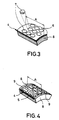
- the zones 5 are by hard body 7 (see Fig. 3) formed by hot isostatic pressing are.
- the wear resistance of such hard body 7 is through the process of hot isostatic pressing and Material composition of the powder metallurgical substance certainly.
- the hard body 7 extend to the Circumference of the roller body 2.
- the spaces 6 are thereby, as already mentioned, by a composite material filled out, its wear properties also by a hot isostatic pressing process and through the powder metallurgical material composition of the Composite is determined.
- the composite and the hard body 7 are together on the base body 2 attached a hot isostatic pressing process.
- the Powder metallurgical wear layer 4 accordingly has one Wear behavior based on the properties of the processing substance is adapted. This is preferred as a starting product for the production of the wear layer 4, highly wear-resistant powder metallurgical materials used, e.g. also contain ceramic components can. Furthermore, the carbide content of the Hard body material and the gap material up to Amount to 65%.
- the area of the highly wear-resistant zones 5 usually takes up approximately 60 to 90% of the total area of the active wear layer 4.
- the size of the area of a wear-resistant zone 5 is usually 1 to 20 cm 2 .
- a press roll 1 is shown on the Outer circumference of the roller base body 2 all around closed bandage 8 is arranged, the form or is frictionally attached to the roller body 2.
- On the wear layer 4 is the outer surface of the bandage 8 upset. The fact that the bandage 8 as a carrier medium for the wear layer 4 is used, the Wear layer easier on the roller body 2 apply.
- FIG. 8 A section of the bandage 8 is shown in FIG whose outside the wear layer 4 over the entire working area A of the wear roller 1 extends.
- the plate-like ones are formed Hard body 7, which in this embodiment Show hexagon shape, very easy to recognize.
- the shape of the Hard body 7 can, however, turn out arbitrarily and accordingly the conditions of use.
- FIG. 4 A second variant of a bandage 8 is shown in FIG. 4, where the wear layer between the work area A laterally bounding, circumferential webs 9 is arranged.
- the webs 9 extend radially to the roller base body 2 outwards and have a height that is approximately the thickness of the Wear layer 4 corresponds. Through the webs 9 is the Wear layer 4 completely bordered on the side, creating a Breaking out of the pages due to excessive pressure in the Edge area can occur.
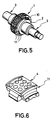
- Fig. 5 shows a third variant of a press roll for Use in a roller press of the present invention whose roller base body 2 is a substantially cylindrical Receiving area 10, on the circumference of several Wear layer 4 on the outside supporting body segments 11 are arranged releasably.
- the basic body segments 11 are form-fitting on the receiving area 10 of the Roller base body 2 placed.
- the shape Base body segments 11 around the receiving area 10 closed ring.
- the segments 11 are by means of Fasteners and the type of tongue and groove connections (see Fig. 6) connected together so that a closed roller surface on the outside is formed.
- the wear layer 4 according to one of the variants of FIG. 3 and 4 can be arranged.
- the method for producing the wear layer 4 is characterized in that first highly wear-resistant material on the roller base 2 is applied so that essentially flat, evenly distributed zones 5 are formed. Next the spaces 6 of the flat zones 5 are filled with a wear-resistant composite material. Of the Zone material and the space material are subsequently on the roller body 2 by a hot isostatic pressing process attached. There are now two Process variants, such as hard body 7 forming zones 5 be produced by a hot isostatic pressing process can.
- the highly wear-resistant becomes Material before application to the roller base 2 Hard body 7 by a hot isostatic pressing process produced. Accordingly, the so generated platelet-shaped hard body 7 on the roller base body 2 in any arrangement and in any own form are applied and the spaces 6 subsequently be filled with a wear-resistant composite. In the subsequent hot isostatic pressing process the composite material in the spaces 6 compressed accordingly and the entire wear layer 4 attached to the roller base body 2.
- the hard bodies 7 from the highly wear-resistant material through the hot isostatic pressing process for attaching the Zone material are manufactured.
- the in particular to produce a wear layer 4 suitable on a base body segment 11 a shape be provided in accordance with the desired Composition of selected powder metallurgical materials be filled in. The shape then positions the corresponding zone material and interspace material the base part.
- the hard body 7 is pressed at the same time manufactured, the composite material in the spaces 6 compacted and the entire wear layer 4 on the base part attached.
- the hot isostatic pressing process can be controlled that the wear resistance of the Hard body 7 and the wear resistance of the Interstices 6 filling composite material only slightly differ from each other. Something each low-wear material range offers through the only slight difference in wear resistance the other material area enough hold on the Roller body 2.
- the wear resistance of the hard body 7 can depending on the desired wear setting profiling be higher or lower than the wear resistance of the space material. For which variant you choose depends on the desired profiling in later operation.
- the wear resistance can be very simple can be adjusted by the respective hard phase content in the hard body material and in the composite material is set accordingly.
- an appropriate Selection of the individual material components of these Powder metallurgical composites can in particular in the second process variant to the fastest possible Wisely and without costly machine retrofitting different wear layers 4, which accordingly the materials to be processed are adapted on the Base part are applied.
- By attaching one such wear layer 4 on a tough base part achieved a combination that is particularly shock and is insensitive to pressure, especially during processing of strongly abrasive substances, e.g. Glass flour, Metallurgical slag or iron and non-ferrous metal ores.
- profiled press rolls 1 has a powder metallurgical Wear layer 4 with different wear zones long service life, although in addition to the large one Compressive stress also a sliding stress of the Surface takes place.
- the present invention provides the Advantage that the "wear layer system" in all Applications such as briquetting, compacting and Shredding is applicable. This will make the Application range of the roller press according to the invention simultaneous increase in tool life significantly expanded.
Description
Die Erfindung bezieht sich auf eine Walzenpresse, insbesondere zum Zerkleinern von stark abrasiven Stoffen, mit mindestens zwei Preßwalzen, die jeweils eine auf einem Grundkörper angeordnete Verschleißschicht aufweisen, wobei die Verschleißschicht im wesentlichen flächige Zonen aus einem hochverschleißfesten Werkstoff aufweist und die Zwischenräume zwischen den hochverschleißfesten Zonen mit einem Werkstoff anderer Verschleißfestigkeit ausgefüllt sind.The invention relates to a roller press, in particular for crushing strongly abrasive substances, with at least two press rolls, each arranged on a base body Have wear layer, the wear layer essentially flat zones from a highly wear-resistant Has material and the spaces between the highly wear-resistant zones with a material of different wear resistance are filled out.
Walzenpressen haben in der Technik in breitem Maße Anwendung gefunden, wobei sich deren Einsatzzwecke im wesentlichen in drei Gruppen Brikettieren, Kompaktieren und Zerkleinern einteilen lassen. Bei allen drei Einsatzfällen üben die Preßwalzen auf die zu verarbeitenden Stoffe eine mehr oder weniger starke Druckbeanspruchung aus. Je nach Profilierung der Preßwalzen kommt es neben dieser Druckbeanspruchung auch zu einer Gleitbeanspruchung an der Walzenoberfläche. Dabei hängt die Intensität der Gleitbeanspruchung im wesentlichen von der Höhe der Druckbeaufschlagung an den Walzen, der Profilierung der Walzenoberfläche und der Eigenschaften der zu verarbeitenden Stoffe ab. Diese Beanspruchung können an den Walzen, insbesondere bei hohen Preßkräften, starken Verschleiß verursachen.Roller presses are widely used in technology found, their uses are essentially in divide three groups of briquetting, compacting and shredding to let. In all three applications, the press rollers practice a more or less strong one on the materials to be processed Pressure load. Depending on the profile of the press rolls in addition to this compressive stress, there is also a sliding stress on the roller surface. The intensity depends the sliding load essentially depends on the amount of pressure applied on the rollers, the profiling of the roller surface and the properties of the substances to be processed. This stress can be on the rollers, especially at high Pressing forces, cause heavy wear.
Im Stand der Technik wurden insbesondere zur Verschleißminderung hochlegierte Stähle beim Brikettieren und Kompaktieren, Auftragsschweißen beim Kompaktieren und Brikettieren und Zerkleinern angewendet. Jedoch war bei diesem Verschleißschutzausbildungen jeweils ein merkliches Absinken der Standzeit zu beobachten, wenn besonders stark abrasive Soffe, wie z.B. Glasmehl, Hüttenschlacke oder Eisen- und Buntmetalle, verarbeitet werden müssen. Beim Zerkleinern ist Autogen-Verschleißschutz bekannt, bei dem die Walzenoberfläche durch sich in die Zwischenräume von auf der Walzenoberfläche angeordneten Noppen absetzenden Partikeln des zu verarbeitenden Stoffes abgedeckt wird. Dieser Autogen-Verschleißschutz ist nicht für Brikettierung geeignet und bietet keine Sicherheit gegen Ausplatzen der eingelagerten, feinkörnigen Partikeln des zu verarbeitenden Stoffes. Beim Auftragsschweißen sind verfahrensbedingte Einschränkungen bezüglich der Legierungszusammensetzung des Schweißgutes gegeben.The prior art has been used in particular to reduce wear high-alloy steels for briquetting and compacting, Cladding during compacting and briquetting and shredding applied. However, this was wear protection training to observe a noticeable decrease in the service life, if particularly strongly abrasive substances, e.g. Glass flour, Metallurgical slag or ferrous and non-ferrous metals, processed Need to become. When shredding is oxy-fuel wear protection known, in which the roller surface through itself in the spaces of knobs arranged on the roller surface Particles of the substance to be processed covered becomes. This oxy-fuel wear protection is not for briquetting suitable and does not offer any security against the blowout embedded, fine-grained particles of the to be processed Fabric. There are procedural restrictions in cladding regarding the alloy composition of the Given weld metal.
Eine gattungsgemäße Walzenpresse, insbesondere eine Mahlwalze, ist aus der EP-A-0516952 bekannt. Dort ist eine Walzenpresse beschrieben, bei der im Umfangsbereich zahlreiche Grundlochbohrungen angeordnet sind, in die stiftförmige Werkstoffstücke eingesteckt sind. Der Hauptteil eines jeweiligen stiftförmigen Werkstoffstückes befindet sich im Walzengrundkörper, während der Rest aus diesem hervorsteht. Die Zwischenräume der igelförmig am Walzengrundkörper vorstehenden stiftförmigen Werkstoffstücke können mit einem aus Kunststoff versetzten, keramischen Material gefüllt sein. Da die verschleißfesten Werkstoffstücke in aller Regel langsamer abnutzen als der Werkstoff in den Zwischenräumen, bildet sich im Betrieb eine profilierte Walzenoberfläche aus. Der Vorteil besteht im besseren Einzugsvermögen und damit dem Erreichen eines höheren Durchsatzes. Die Herstellung solcher bekannten Walzenpressen ist jedoch durch das Einbringen der zahlreichen Verankerungsgrundlöcher in den Walzengrundkörper sehr zeitintensiv und damit entsprechend mit hohen Kosten verbunden. Des weiteren ist bei dieser Lösung die Gefahr des Ausbrechens von Stiften sehr groß.A generic roller press, in particular a grinding roller, is known from EP-A-0516952. There is a roller press described in the numerous blind holes in the peripheral area are arranged in the pin-shaped material pieces are plugged in. The main part of each pen-shaped The piece of material is in the roller body while the rest of it sticks out. The spaces between the hedgehog-shaped pin-shaped material pieces protruding from the roller base body can be made with a ceramic plastic Material. Because the wear-resistant pieces of material usually wear more slowly than the material in the gaps, a profiled is formed during operation Roller surface. The advantage is better pull-in capacity and thus achieving a higher throughput. The Manufacture of such known roller presses is however through the introduction of the numerous anchoring blind holes in the Roller body very time-consuming and therefore with associated with high costs. Furthermore, this solution is There is a very high risk of pins breaking out.
Aus der EP-A-0271336 ist eine Walze bekannt, bei der in die Längsnuten zwischen, bevorzugt aus dem Walzengrundmaterial bestehenden Stegen ein verschleißfestes Material eingebracht wird, so daß es im späteren Betrieb zu einer Verschleißprofilierung der Oberfläche kommt.From EP-A-0271336 a roller is known in which in the Longitudinal grooves between, preferably consisting of the roll base material Webs introduced a wear-resistant material is so that it becomes a wear profiling in later operation the surface is coming.
Des weiteren ist aus der DE-A-2133300 eine durch heißisostatisches Pressen hergestellte Verschleißschicht für eine Preßwalze bekannt, die als geschlossene Außenschicht auf ein Trägermaterial aufgebracht wird. Furthermore, from DE-A-2133300 is a hot isostatic Press-produced wear layer for a press roll known as a closed outer layer on a carrier material is applied.
Es ist die Aufgabe der vorliegenden Erfindung, eine Walzenpresse der eingangs genannten Art bereitzustellen, die eine hohe Standzeit aufweist und für alle Anwendungsfälle (Brikettieren, Kompaktieren und Zerkleinern) verwendbar und einfach herstellbar ist.It is the object of the present invention, a roller press of the type mentioned that provide a high Has a service life and for all applications (briquetting, Compacting and shredding) usable and easy to manufacture is.
Die Aufgabe der vorliegenden Erfindung wird dadurch gelöst, daß der Zwischenraumwerkstoff ein sinterfähiger Verbundwerkstoff ist und die hochverschleißfesten Zonen aus durch heißisostatisches Pressen hergestellte Hartkörper gebildet sind, wobei der Zwischenraumwerkstoff und der Werkstoff der verschleißfesten Zonen durch einen heißisostatischen Preßvorgang am Grundkörper befestigt sind und wobei die Verschleißfestigkeit des Zwischenraumwerkstoffes entsprechend einer gewünschten, sich durch Verschleiß einstellenden Profilierung im wesentlichen geringfügig höher oder niedriger ist als die Verschleißfestigkeit der Hartkörper.The object of the present invention is achieved in that the intermediate material is a sinterable composite material is and the highly wear-resistant zones from hot isostatic Pressed hard body are formed, the Intermediate material and the material of the wear-resistant Zones through a hot isostatic pressing process on the base body are attached and the wear resistance of the intermediate material according to a desired, due to wear adjusting profiling essentially slightly is higher or lower than the wear resistance of the hard body.
Demnach handelt es sich bei der erfindungsgemäßen Verschleißschicht um eine pulvermetallurgische Hartschicht, die flächige Zonen und gefüllte Zwischenräume mit jeweils unterschiedlichen Verschleißeigenschaften aufweist. Dadurch stellt sich nach einer gewissen Einsatzzeit eine Profilierung an der Walzenoberfläche ein, die den gewünschten besseren Einzug des zu verarbeitenden Materials mit sich bringt. Da es sich bei dem Zonenwerkstoff und dem Verbundwerkstoff jeweils um pulvermetallurgisch herzustellende Werkstoffe handelt, sind diese durch heißisostatisches Pressen an dem Walzengrundkörper anbringbar. Der heißisostatische Preßvorgang sorgt dafür, daß die gesamte Verschleißschicht eine Verbindung mit dem Walzengrundkörper aufweist, die solch eine Festigkeit hat, daß nicht einzelne Bestandteile der Verschleißschicht aus dieser herausgelöst werden können. Zwar sind pulvermetallurgische Hartschichten, die durch heißisostatisches Pressen hergestellt werden, im Stand der Technik bekannt. Sie sind jedoch nie in der erfindungsgemäßen Weise als Verschleißschicht in Walzenpressen eingesetzt worden. Der Grund dafür liegt offensichtlich in den relativ rauhen Arbeitsbedingungen für Walzenpressen, da pulvermetallurgische Hartstoffe relativ schlag- und stoßempfindlich sind. Durch die erfindungsgemäße Anordnung von Zonen und Zwischenräumen mit unterschiedlichen Verschleißeigenschaften auf einem relativ zähen Grundkörper können jedoch solche Beanspruchungen leicht aufgefangen werden. Verbessert werden kann die Stoßunempfindlichkeit insbesondere auch dadurch, daß entweder der Hartkörperwerkstoff oder der Zwischenraumwerkstoff von einem relativ duktilen Werkstoff umgeben ist. Des weiteren ist eine Verankerung bestimmter Bestandteile der Verschleißschicht im Walzengrundkörper, wie es im Stand der Technik vorgesehen ist, bei heißisostatischer Befestigung nicht mehr nötig. Durch die Erzielung höherer Standzeiten bei Verwendung einer pulvermetallurgischen Verschleißschicht mit Zonen unterschiedlicher Verschleißfestigkeit kann die Anwendungsbreite von Walzenpressen erheblich erweitert werden. Die erfindungsgemäße Lösung ist gleichsam für die Brikettierung, Kompaktierung und Zerkleinerung von stark abrasiven Stoffen geeignet, wobei die Standzeit nennenswert erhöht wird. Durch das Herstellen der Hartschicht durch heißisostatisches Pressen kann der Verschleißschicht auf einfache Weise jede gewünschte Form verliehen werden. Des weiteren kann eine solche Verschleißschicht in einem Arbeitsgang hergestellt werden, weshalb sich die Zeit und die Kosten zur Herstellung einer solchen Walzenpresse reduzieren lassen.Accordingly, it is the wear layer according to the invention a powder metallurgical hard layer, the flat one Zones and filled spaces with different ones Has wear properties. This turns into one profiling on the roller surface after a certain period of use a, which the desired better indentation of the to be processed Material. Since it is the zone material and the composite material in each case by powder metallurgy materials to be produced are hot isostatic Presses attachable to the roller body. Of the hot isostatic pressing process ensures that the entire wear layer has a connection to the roller body, which is so firm that not individual components the wear layer can be removed from this can. Although powder metallurgical hard layers that are caused by hot isostatic pressing are manufactured in the state of the Technology known. However, they are never in the invention Were used as a wear layer in roller presses. The reason for this is obviously the relatively harsh working conditions for roller presses, since powder metallurgical Hard materials are relatively sensitive to impact and shock. Through the arrangement of zones and spaces according to the invention with different Wear properties on a relatively tough However, basic bodies can easily absorb such stresses will. Impact resistance can be improved in particular also in that either the hard body material or the intermediate material from a relatively ductile material is surrounded. Anchoring is also more specific Components of the wear layer in the roller body, like it is provided in the prior art, with hot isostatic attachment no longer necessary. By achieving a longer service life when using a powder metallurgical wear layer with zones of different wear resistance the range of applications of roller presses can be expanded considerably. The solution according to the invention is as it were for briquetting, Compacting and crushing highly abrasive Suitable materials, whereby the service life is significantly increased. By creating the hard layer through hot isostatic The wear layer can easily press any desired Be given shape. Furthermore, such Wear layer can be produced in one operation, which is why yourself the time and cost of making one Have the roller press reduced.
Um eine entsprechende Profilierung im Betrieb auszubilden, die an einen bestimmten zu bearbeitenden Stoff angepaßt ist, kann das Verhältnis der Verschleißfestigkeit des Verbundwerkstoffes und die Verschleißfestigkeit der Hartkörper jeweils auf den zu verarbeitenden, abrasiven Stoff abgestimmt sein. Das stellt insbesondere bei der Herstellung einer solchen Verschleißschicht kein nenneswertes Problem dar, weil die pulvermetallurgischen Werktsoffe bezüglich ihrer Zusammensetzung jeweils entsprechend des Anwendungsfalles aufeinander abgestimmt werden können. Hierbei kann auch das Gesamtniveau der Verschleißfestigkeit der beiden Werkstoffe angehoben oder gesenkt werden.To develop a corresponding profile in the company, the is adapted to a specific substance to be processed, can the ratio of the wear resistance of the composite and the wear resistance of the hard body to each processing, abrasive material. That poses especially in the production of such a wear layer not a noteworthy problem because the powder metallurgical Materials in terms of their composition coordinated according to the application can be. Here, the overall level of Wear resistance of the two materials raised or be lowered.
Bevorzugt sind die Hartkörper an ihren Verbundwerkstoff eingebetteten Umfang zumindest bereichsweise mit dem Verbundwerkstoff stoffschlußartig verbunden. Eine solche Verbindung kann durch den heißisostatischen Preßvorgang zwangsläufig erreicht werden und ist daher sehr einfach ausführbar. Die Hartkörper und der Zwischenraumwerkstoff weisen jeweils an ihren Berührungsstellen einen Diffusionsbereich auf, der zu einem sehr starken Anhaften der beiden Werkstoffe aneinander führt.The hard bodies are preferred on their composite material embedded scope at least in some areas with the Composite material bonded. Such Connection can by the hot isostatic pressing process can inevitably be achieved and is therefore very simple executable. The hard body and the space material have one at their contact points Diffusion area leading to very strong adherence leads the two materials together.
Eine optimale Profilierung kann im Betrieb der Walzenpresse dadurch erreicht, daß die Fläche der Hartkörper ca. 60% bis 90% der Gesamtfläche der aktiven Verschleißschicht einnimmt. Unter aktiver Verschleißschicht wird jeweils der Bereich der Verschleißschicht verstanden, der an dem Verarbeitungsvorgang der abrasiven Stoffe teilnimmt.Optimal profiling can be achieved in the operation of the roller press achieved in that the area of the hard body is about 60% to 90% of the total area of the active wear layer. The area of the Understand the wear layer on the Processing process of the abrasive substances takes part.
Die hochverschleißfesten Zonen sind insbesondere dann einfach herzustellen, wenn die Hartkörper plättchenförmig ausgebildet sind. Solche plättchenförmigen Hartkörper können z.B. vorab auf dem Walzenkörper aufgebracht und anschließend die Zwischenräume mit Verbundwerkstoff gefüllt werden. Die Form der plättchenförmigen Hartkörper kann dabei beliebig ausfallen.The highly wear-resistant zones are especially then easy to manufacture if the hard body is platelet-shaped are trained. Such platelet-shaped hard bodies can e.g. applied in advance on the roller body and then the spaces are filled with composite material. The The shape of the platelet-shaped hard body can be arbitrary fail.
Insbesondere werden dann günstige Verschleißeigenschaften der Verschleißschicht erreicht, wenn der Hartkörperwerkstoff und der Zwischenraumwerkstoff einen Karbidanteil von bis zu 65% aufweisen. In particular, then there are favorable wear properties the wear layer is reached when the hard body material and the space material has a carbide content of up to Have 65%.
Zur Verbesserung der Profilierung trägt weiterhin bei, wenn die Größe der Fläche einer verschleißfesten Zone ca. 1 bis 20 cm2 beträgt.The profiling is further improved if the size of the area of a wear-resistant zone is approximately 1 to 20 cm 2 .
Die Standzeit kann insbesondere weiterhin beträchtlich erhöht werden, wenn die Verschleißschicht keramische Bestandteile aufweist.The service life can continue to be considerable be increased if the wear layer is ceramic Has components.
Bevorzugt weist die Verschleißschicht ein sehr feinkörniges Gefüge auf, wodurch eine größere Festigkeit, Härte, Zähigkeit und Kerbschlagarbeit erreicht wird.The wear layer preferably has a very fine-grained one Structure, which gives greater strength, hardness, Toughness and impact energy is achieved.
In einer bevorzugten Ausführungsform ist die Verschleißschicht auf der gesamten Oberfläche des Arbeitsbereichs der Preßwalze flächig aufgebracht. Bevorzugt wird auch eine Ausführung bei der die Verschleißschicht zwischen den Arbeitsbereich seitlich begrenzenden, umlaufenden Stegen angeordnet ist, die sich radial zum Walzengrundkörper nach außen erstrecken. Hierdurch ist die Hartschicht an ihrem Rand durch eine mittels der Stege gebildete Einfassung umgeben, die verhindert, daß die seitlichen Kanten der Hartschicht durch Stoß- und Kantenbelastung ausbrechen.In a preferred embodiment, the Wear layer on the entire surface of the Working area of the press roll applied flat. Prefers will also be a version in which the wear layer between the work area, circumferential webs is arranged, which is radial to Extend the roller base outwards. This is the Hard layer on its edge by means of the webs surround formed, which prevents the lateral edges of the hard layer by impact and Break out edge load.
Eine weitere Ausgestaltung schlägt vor, daß in den Außenmantel des Walzengrundkörpers im Arbeitsbereich der Preßwalze mehrere im wesentlichen am Umfang gleichmäßig verteilte, taschenförmige Vertiefungen eingebracht sind, in denen jeweils die Verschleißschicht aufgenommen ist. Bei einer solchen Ausgestaltung kann je nach Einsatzfall eine entsprechende Größen- und Flächenverteilung der Verschleißschicht am Walzenumfang erreicht werden.A further embodiment suggests that in the Outer jacket of the roller body in the work area of Press roll several substantially evenly around the circumference distributed, pocket-shaped depressions are introduced, in which each have the wear layer recorded. At Such an embodiment can, depending on the application corresponding size and area distribution of the Wear layer on the roller circumference can be reached.
Insbesondere kann die Preßwalze eine profilierte Oberfläche, bevorzugt eine Brikettprofilierung, aufweisen. Die Verschleißschicht hält insbesondere den Gleitbewegungen an der Oberfläche der einzelnen Brikettprofile in der Preßwalze stand, wodurch während einer nennenswerten Standzeit eine gewünschte Formtoleranz bereitgestellt werden kann.In particular, the press roll can have a profiled surface, preferably have a briquette profile. The Wear layer especially stops the sliding movements the surface of the individual briquette profiles in the press roll stood, whereby a during a significant service life desired shape tolerance can be provided.
In günstiger Weise kann in einer weiteren Ausführungsform der Walzengrundkörper einen im wesentlichen zylindrischen Aufnahmebereich aufweisen, auf dessen Umfang mehrere die pulvermetallurgische Verschleißschicht auf der Außenseite tragende Grundkörper-Segmente lösbar angeordnet sind. Hierdurch läßt sich die Verschleißschicht besonders einfach auch bei relativ großen Preßwalzendurchmessern herstellen. Zudem ist bei jedem Segment sichergestellt, daß die Verschleißschicht eine gleichmäßige Verteilung von hochverschleißfesten Zonen und Zwischenräumen aufweist, da ihre Abmessung entsprechend den günstigsten Herstellungsbedingungen für heißisostatisches Pressen gewählt werden können. Dies kann in Abhängigkeit von der Anzahl der verwendeten Segmente geschehen. Bevorzugt bilden hierbei die Grundkörper-Segmente um den Aufnahmebereich einen geschlossen Ring.A further embodiment can be used in a favorable manner the roller base body is essentially cylindrical Have recording area on the circumference of several powder metallurgical wear layer on the outside load-bearing basic body segments are arranged detachably. This makes the wear layer particularly easy produce even with relatively large press roll diameters. In addition, it is ensured for each segment that the Wear layer an even distribution of has highly wear-resistant zones and spaces, because their dimensions according to the cheapest Manufacturing conditions for hot isostatic pressing can be chosen. This can vary depending on the Number of segments used happen. Form preferred here the basic body segments around the recording area a closed ring.
In einer weiteren Ausführungsform ist die Verschleißschicht auf einer geschlossen Bandage aufgebracht, die form- oder reibschlüssig auf dem Walzengrundkörper angeordnet ist. Durch eine solche Ausgestaltung kann die Hartschicht mit relativ geringem Aufwand auf dem Walzengrundkörper angeordnet werden. Insbesondere bei einer aufgeschrumpften Bandage kann durch eine entsprechende Einstellung des Werkstoffes, insbesondere ein duktiler Werkstoff, der Stege die Bildung von Rissen infolge von Schrumpfspannungen vermieden werden.In a further embodiment, the wear layer applied on a closed bandage, the form or is frictionally arranged on the roller body. With such a configuration, the hard layer can also relatively little effort on the roller base to be ordered. Especially with a shrunk on Bandage can be adjusted accordingly Material, especially a ductile material, the webs the formation of cracks due to shrinkage stresses be avoided.
Des weiteren wird für ein Verfahren zum Herstellen einer
Verschleißschicht, insbesondere für eine Preßwalze zum
Verarbeiten von stark abrasiven Stoffen, Schutz begehrt
werden. Das Verfahren umfaßt die folgenden Schritte:
Das Verfahren bietet den Vorteil, durch lediglich Verändern einiger Verfahrens- oder Werkstoffparameter eine Verschleißschicht herzustellen, die sehr unterschiedliche Verschleißeigenschaften aufweist. Aus diesem Grunde kann z.B. die Verschleißschicht einer Preßwalze in ihrem Verschleißverhalten dem zu verarbeitenden, abrasiven Stoff angepaßt werden.The method offers the advantage of only changing some process or material parameters Manufacture wear layer that is very different Has wear properties. Because of this, can e.g. the wear layer of a press roll in your Wear behavior of the abrasive material to be processed be adjusted.
Bei einer weiteren Verfahrensvarianten können aus dem hochverschleißfesten Werkstoff vor dem Aufbringen auf das Basisteil durch einen heißisostatischen Preßvorgang Hartkörper hergestellt werden. Die Hartkörper können somit jede beliebige Form erhalten und entsprechend der später gewünschten Profilierung auf dem Basisteil aufgebracht werden.In a further process variant, the highly wear-resistant material before application to the Base part through a hot isostatic pressing process Hard bodies are made. The hard body can thus get any shape and according to the later desired profile applied to the base part will.
Es ist jedoch auch möglich, aus dem hochverschleißfesten Werkstoff durch den heißisostatischen Preßvorgang zum Anbringen des Zonenwerkstoffs am Basisteil Hartkörper herzustellen. Das bedeutet, daß lediglich ein einziger heißisostatischer Preßvorgang ausgeführt werden muß, um gleichzeitig Hartkörper herzustellen und diese zusammen mit dem Verbundwerkstoff am Basisteil zu befestigen. However, it is also possible to use the highly wear-resistant Material through the hot isostatic pressing process to Attach the zone material to the base part hard body to manufacture. That means that only one hot isostatic pressing must be carried out in order at the same time to produce hard bodies and these together with attach the composite to the base.
Günstigerweise kann der heißisostatische Preßvorgang so gesteuert werden, daß die Verschleißfestigkeit der Hartkörper und die Verschleiflfestigkeit der Zwischenräume füllenden Verbundwerkstoffe nur geringfügig voneinander abweichen, wobei die Verschleißfestigkeit der Hartkörper je nach gewünschter, sich durch den Verschleiß einstellenden Profilierung höher oder niedriger ist als die Verschleißfestigkeit des Zwischenraumwerkstoffes. Da die Verschleißfestigkeiten nur geringfügig voneinander abweichen, ist sichergestellt, daß der gesamte Verschleißwiderstand der Verschleißschicht relativ hoch ist, sich dennoch eine Profilierung zur Verbesserung des Einzugs des zu verarbeitenden abrasiven Stoffes einstellt.Conveniently, the hot isostatic pressing process can be controlled that the wear resistance of the Hard body and the wear resistance of the gaps filling composites only slightly apart deviate, the wear resistance of the hard body depending according to the desired, resulting from wear Profiling is higher or lower than that Wear resistance of the space material. Since the Wear resistance only slightly apart deviate, it is ensured that the entire Wear resistance of the wear layer is relatively high, there is still a profiling to improve the feeder of the abrasive material to be processed.
Weiterhin kann die Verschleißfestigkeit durch den jeweiligen zugeführten Gehalt an Hartphasen in den Hartkörperwerkstoff oder in den Verbundwerkstoff entsprechend eingestellt werden. Durch simple unterschiedliche Mischungsverhältnisse der ausgewählten pulvermetallurgischen Werkstoffe kann somit das Verschleißverhalten der Zonen und der gefüllten Zwischenräume eingestellt werden, wodurch sich auch das gesamte Verschleißverhalten der Verschleißschicht ändert.Furthermore, the wear resistance can be affected by the respective supplied hard phase content in the hard body material or adjusted accordingly in the composite material will. Through simple different mixing ratios the selected powder metallurgical materials can the wear behavior of the zones and the filled Spaces are set, which also changes overall wear behavior of the wear layer changes.
Im folgenden werden Ausführungsbeispiele der vorliegenden Erfindung anhand einer Zeichnung näher erläutert. Es zeigen:
- Fig. 1
- eine Preßwalze für eine Walzenpresse gemäß der vorliegenden Erfindung,
- Fig. 2
- eine zweite Ausführungsform einer Preßwalze mit Bandage,
- Fig. 3
- einen Teil der Bandage aus Fig. 2 in einer vergrößerten Darstellung,
- Fig. 4
- eine zweite Variante einer Bandage,
- Fig. 5
- eine dritte Ausführungsform einer Preßwalze mit Grundkörpersegmenten und
- Fig. 6
- ein Grundkörpersegment aus Fig. 5 in vergrößerter Darstellung.
- Fig. 1
- a press roll for a roll press according to the present invention,
- Fig. 2
- a second embodiment of a press roll with a bandage,
- Fig. 3
- 2 shows an enlarged view of part of the bandage from FIG. 2,
- Fig. 4
- a second variant of a bandage,
- Fig. 5
- a third embodiment of a press roll with base body segments and
- Fig. 6
- a basic body segment of FIG. 5 in an enlarged view.
Fig. 1 zeigt eine Preßwalze 1, die mit einer gleich
aufgebauten Preßwalze zum Einsatz in einer Walzenpresse zum
Preßverdichten oder zum Zerkleinern von stark abrasiven
Stoffen vorgesehen ist. Die Preßwalze 1 besteht im
wesentlichen aus einem zylindrischen Walzengrundkörper 2, an
dem auf beiden Seiten koaxial angeordnete Lagerzapfen 3
vorgesehen sind. Als Verschleißschutz weist die Preßwalze 1
eine auf dem Grundkörper 2 angeordnete, pulvermetallurgische
Verschleißschicht 4 auf, die durch heißisostatisches Pressen
hergestellt ist. Die Verschleißschicht besteht aus Zonen 5,
aus einem hochverschleißfesten Werkstoff und einem die
Zwischenräume 6 der Zonen 5 füllenden verschleißfesten
Verbundwerkstoff. Das Verschleißverhalten der Zonen 5 und
der Zwischenräume 6 ist auf die Eigenschaft des zu
verarbeitenden, abrasiven Stoffes abgestimmt. Die Zonen 5
und die Zwischenräume 6 weisen hierbei ein unterschiedliches
Verschleißverhalten auf, wodurch sich dem Betrieb der
Walzenpresse eine Oberflächenprofilierung der Presswalzen 1
einstellt. Die Zonen 5 sind durch Hartkörper 7 (siehe Fig.
3) gebildet, die durch heißisostatisches Pressen hergestellt
sind. Die Verschleißfestigkeit solcher Hartkörper 7 wird
durch den Vorgang des heißisostatischen Pressens und die
Werkstoffzusammensetzung des pulvermetallurgischen Stoffes
bestimmt. Die Hartkörper 7 erstrecken sich bis auf den
Umfang des Walzengrundkörpers 2. Die Zwischenräume 6 sind
dabei, wie schon erwähnt, durch einen Verbundwerkstoff
ausgefüllt, dessen Verschleißeigenschaften ebenfalls durch
einen heißisostatischen Preßvorgang und durch die
pulvermetallurgische Werkstoffzusammensetzung des
Verbundwerkstoffes bestimmt wird. Der Verbundwerkstoff und
die Hartkörper 7 werden zusammen am Grundkörper 2 durch
einen heißisostatischen Preßvorgang befestigt. Hierdurch
bilden sich an den Berührungsstellen der Hartkörper 7 und
des Verbundwerkstoffes, sowie an den Berührungsstellen der
Hartkörper 7 und des Verbundwerkstoffes mit dem
Walzengrundkörper 2 Diffusionszonen aus, die zu einer festen
Anbindung der einzelnen Werkstoffe führen. Die
pulvermetallurgische Verschleißschicht 4 weist demnach ein
Verschleißverhalten auf, das den Eigenschaften des zu
verarbeitenden Stoffes angepaßt ist. Hierzu werden bevorzugt
als Ausgangsprodukt zur Herstellung der Verschleißschicht 4,
hochverschleißfeste pulvermetallurgische Werkstoffe
eingesetzt, die z.B. auch keramische Bestandteile enthalten
können. Des weiteren kann der Karbidanteil des
Hartkörperwerkstoffs und des Zwischenraumwerkstoffes bis zu
65% betragen. Die Kombination relativ zäher Walzengrundkörper
2 mit einer sehr verschleißfesten
pulvermetallurgischen Verschleißschicht 4, die aus Zonen 5
und Zwischenräumen 6 mit unterschiedlichen
Verschleißeigenschaften besteht, ergibt eine relativ hohe
Verschleißfestigkeit, bei denen bei einer Walzenpresse
vorherrschenden Betriebsbedingungen während, z.B. des
Brikettierens, Kompaktierens und Zerkleinerns. Eine solche
Preßwalze 1 zum Einsatz in einer erfindungsgemäßen
Walzenpresse wiedersteht selbst großen Druckbelastungen, die
auf die pulvermetallurgische Verschleißschicht 4 wirken, bei
gleichzeitger Gleitbeanspruchung entlang der
Walzenoberfläche. Aus diesem Grunde sind die Preßwalzen 1
besonders gut zur Preßverdichtung oder Zerkleinerung von
stark abrasiven Stoffen, wie z.B. Glasmehl, Hüttenschlacke
oder Eisen- und Buntmetallerze, geeignet.Fig. 1 shows a
Die Fläche der hochverschleißfesten Zonen 5 nimmt
üblicherweise ca. 60 bis 90% der Gesamtfläche der aktiven
Verschleißschicht 4 ein. Dabei beträgt die Größe der Fläche
einer verschleißfesten Zone 5 in der Regel 1 bis 20 cm2. The area of the highly wear-
Hierdurch stellt sich eine entsprechend gewünschte Profilierung im späteren Betrieb ein.This creates a correspondingly desired one Profiling in later operation.
In Fig. 2 ist eine Preßwalze 1 dargestellt, auf deren
Außenumfang des Walzengrundkörpers 2 eine umlaufend
geschlossene Bandage 8 angeordnet ist, die form- oder
reibschlüssig auf dem Walzengrundkörper 2 befestigt ist. Auf
der Außenfläche der Bandage 8 ist die Verschleißschicht 4
aufgebracht. Dadurch, daß die Bandage 8 als Trägermedium für
die Verschleißschicht 4 dient, läßt sich die
Verschleißschicht einfacher auf den Walzengrundkörper 2
aufbringen.In Fig. 2, a
In Fig. 3 wird ein Ausschnitt der Bandage 8 gezeigt, auf
deren Außenseite sich die Verschleißschicht 4 über den
gesamten Arbeitsbereich A der Verschleißwalze 1 erstreckt.
In dieser Fig. sind die plättchenförmig ausgebildeten
Hartkörper 7, die bei dieser Ausführungsform eine
Sechseckform aufweisen, sehr gut zu erkennen. Die Form der
Hartkörper 7 kann jedoch beliebig ausfallen und entsprechend
den Einsatzbedingungen gewählt werden.A section of the
Eine zweite Variante einer Bandage 8 ist in Fig. 4 gezeigt,
bei der die Verschleißschicht zwischen den Arbeitsbereich A
seitlich begrenzenden, umlaufenden Stegen 9 angeordnet ist.
Die Stege 9 erstrecken sich radial zum Walzengrundkörper 2
nach außen und weisen eine Höhe auf, die etwa der Dicke der
Verschleißschicht 4 entspricht. Durch die Stege 9 ist die
Verschleißschicht 4 seitlich komplett eingefaßt, wodurch ein
Ausbrechen der Seiten durch zu große Druckbelastung im
Kantenbereich auftreten kann.A second variant of a
Es sei an dieser Stelle erwähnt, daß sämtliche
Anordnungsformen der Verschleißschicht 4, wie sie in den
Fig. 3 und 4 dargestellt sind, ohne weiteres auf die in Fig.
1 gezeigte Ausführungsform einer Preßwalze 1 übertragen
werden können. Hierbei werden z.B. die Stege direkt aus dem
Walzengrundkörper 2 herausgearbeitet, ohne daß eine Bandage
8 dazwischengeschaltet ist.At this point it should be mentioned that all
Arrangement forms of the
Fig. 5 zeigt eine dritte Variante einer Preßwalze zum
Einsatz in einer Walzenpresse der vorliegenden Erfindung,
deren Walzengrundkörper 2 ein im wesentlichen zylindrischen
Aufnahmebereich 10 aufweist, auf dessen Umfang mehrere, die
Verschleißschicht 4 auf der Außenseite tragende Grundkörper-Segmente
11 lösbar angeordnet sind. Der Grundkörper-Segmente
11 sind formschlüssig auf dem Aufnahmebereich 10 des
Walzengrundkörpers 2 aufgesetzt. Dabei formen die
Grundkörper-Segmente 11 um den Aufnahmebereich 10 einen
geschlossenen Ring. Die Segmente 11 werden mittels
Verbindungselementen sowie nach Art der Nut- und Feder-Verbindungen
(siehe Fig. 6) miteinander verbunden, so daß
auf der Außenseite eine geschlossene Walzenoberfläche
gebildet wird. Auf der Außenseite der Segmente 11 kann dann
die Verschleißschicht 4 gemäß einer der Varianten von Fig. 3
und 4 angeordnet werden.Fig. 5 shows a third variant of a press roll for
Use in a roller press of the present invention
whose
Im folgenden wird das Herstellungsverfahren der Verschleißschicht für die erfindungsgemäße Walzenpresse kurz erläutert.In the following the manufacturing process of Wear layer for the roller press according to the invention short explained.
Das Verfahren zum Herstellen der Verschleißschicht 4
zeichnet sich dadurch aus, daß zuerst ein
hochverschleißfester Werkstoff auf den Walzengrundkörper 2
aufgebracht wird, so daß im wesentlichen flächige,
gleichmäßig verteilte Zonen 5 gebildet werden. Als nächstes
erfolgt ein Füllen der Zwischenräume 6 der flächigen Zonen 5
mit einem verschleißfesten Verbundwerkstoff. Der
Zonenwerkstoff und der Zwischenraumwerkstoff werden
nachfolgend auf dem Walzengrundkörper 2 durch einen
heißisostatischen Preßvorgang angebracht. Es gibt nun zwei
Verfahrensvarianten, wie die Zonen 5 bildenden Hartkörper 7
durch eine heißisostatischen Preßvorgang hergestellt werden
können. The method for producing the
Bei der ersten Varianten wird aus dem hochverschleißfesten
Werkstoff vor dem Aufbringen auf den Walzengrundkörper 2 die
Hartkörper 7 durch einen heißisostatischen Preßvorgang
hergestellt. Demnach können die so erzeugten
plättchenförmigen Hartkörper 7 auf dem Walzengrundkörper 2
in beliebiger Anordnung und in beliebiger eigener Form
aufgebracht werden und die Zwischenräume 6 anschließend
durch einen verschleißfesten Verbundstoff gefüllt werden.
Bei dem dann nachfolgenden heißisostatischen Preßvorgang
wird dann der Verbundwerkstoff in den Zwischenräumen 6
entsprechend verdichtet und die gesamte Verschleißschicht 4
an dem Walzengrundkörper 2 angebracht.In the first variant, the highly wear-resistant becomes
Material before application to the
Bei der zweiten Verfahrensvariante können die Hartkörper 7
aus dem hochverschleißfesten Werkstoff durch den
heißisostatischen Preßvorgang zum Anbringen des
Zonenwerkstoffs hergestellt werden. Bei dieser Variante, die
sich insbesondere zur Erzeugung einer Verschleißschicht 4
auf einem Grundkörper-Segment 11 eignet, kann eine Form
bereitgestellt werden, in die entsprechend der gewünschten
Zusammensetzung ausgewählte, pulvermetallurgische Werkstoffe
eingefüllt werden. Die Form positioniert dann den
entsprechenden Zonenwerkstoff und Zwischenraumwerkstoff auf
dem Basisteil. Bei dem anschließenden heißisostatischen
Preßvorgang werden gleichzeitig die Hartkörper 7
hergestellt, der Verbundwerkstoff in den Zwischenräumen 6
verdichtet und die gesamte Verschleißschicht 4 am Basisteil
befestigt.In the second method variant, the hard bodies 7
from the highly wear-resistant material through the
hot isostatic pressing process for attaching the
Zone material are manufactured. In this variant, the
in particular to produce a
Insbesondere kann der heißisostatische Preßvorgang so
gesteuert werden, daß die Verschleißfestigkeit der
Hartkörper 7 und die Verschleißfestigkeit des die
Zwischenräume 6 füllenden Verbundwerkstoffs nur geringfügig
voneinander abweichen. Der jeweils etwas
verschleißschwächere Werkstoffbereich bietet durch die nur
geringfügige Unterschiedlichkeit der Verschleißfestigkeit
dem jeweils anderen Werkstoffbereich genügend Halt auf dem
Walzengrundkörper 2. Die Verschleißfestigkeit der Hartkörper
7 kann je nach gewünschter, sich durch Verschleiß
einstellenden Profilierung höher oder niedriger sein, als
die Verschleißfestigkeit des Zwischenraumwerkstoffes. Für
welche Variante man sich entscheidet, hängt von der
gewünschten Profilierung im späteren Betrieb ab.In particular, the hot isostatic pressing process can
be controlled that the wear resistance of the
Hard body 7 and the wear resistance of the
Des weiteren kann die Verschleißfestigkeit sehr einfach
eingestellt werden, indem der jeweilige Gehalt an Hartphasen
in den Hartkörperwerkstoff und in den Verbundwerkstoff
entsprechend eingestellt wird. Durch eine entsprechende
Auswahl der einzelnen Werkstoffbestandteile dieser
pulvermetallurgischen Verbundwerkstoffe können insbesondere
bei der zweiten Verfahrensvariante auf schnellstmögliche
Weise und ohne kostenintensive Umrüstung der Maschinen
unterschiedliche Verschleißschichten 4, die entsprechend an
die zu verarbeitenden Materialien angepaßt sind, auf dem
Basisteil aufgebracht werden. Durch das Anbringen einer
solchen Verschleißschicht 4 auf einem zähen Basisteil wird
eine Kombination erreicht, die besonders stoß- und
druckunempfindlich ist, insbesondere bei der Verarbeitung
von stark abrasiven Stoffen, wie z.B. Glasmehl,
Hüttenschlacke oder Eisen- und Buntmetallerze. Speziell bei
profilierten Preßwalzen 1 weist eine pulvermetallurgische
Verschleißschicht 4 mit unterschiedlichen Verschleißzonen
große Standzeiten auf, obwohl neben der großen
Druckbeanspruchung auch eine Gleitbeanspruchung der
Oberfläche stattfindet. Dies unterstützt in positivem Maße
die Formstabilität der auf Walzenoberfläche eingebrachten
Formen. Des weitern bietet die vorliegende Erfindung den
Vorteil, daß das "Verschleißschichtsystem" bei sämtlichen
Einsatzfällen, wie Brikettieren, Kompaktieren und
Zerkleinern anwendbar ist. Hierdurch wird die
Anwendungsbreite der erfindungsgemäßen Walzenpresse bei
gleichzeitiger Erhöhung der Standzeit erheblich erweitert.Furthermore, the wear resistance can be very simple
can be adjusted by the respective hard phase content
in the hard body material and in the composite material
is set accordingly. By an appropriate
Selection of the individual material components of these
Powder metallurgical composites can in particular
in the second process variant to the fastest possible
Wisely and without costly machine retrofitting
Claims (21)
- A roll press, in particular for processing very abrasive materials, comprising at least two press rolls (1) of which each includes a wear layer (4) arranged on a basic body (2), said wear layer (4) comprising substantially plane zones (5) of a highly wear-resistant material, and spaces (6) between said highly wear-resistant zones (5) being filled with a material of different wear resistance, characterized in that the material for said spaces is a composite material which is adapted to be sintered, and said highly wear-resistant zones (5) are made from hard bodies (7) produced by hot-isostatic pressing, the material for said spaces and the material for said wear-resistant zones (5) being bonded to said basic body (2) in a hot-isostatic pressing operation, and the wear resistance of the material for said spaces being substantially slightly greater or smaller than the wear resistance of said hard bodies (7) in accordance with a desired profile which will be obtained through wear.
- The roll press according to claim 1, characterized in that the ratio of the wear resistance of said composite material to the wear resistance of said hard bodies (7) is respectively adapted to the abrasive material to be processed.
- The roll press according to claim 1 or 2, characterized in that said hard bodies (7) establish an integral connection, at least in regions, with said composite material on their circumference embedded in said composite material.
- The roll press according to any one of claims 1 to 3, characterized in that the area of said highly wear-resistant zones (5) occupies about 60 to 90% of the total surface of said active wear layer (4).
- The roll press according to any one of claims 1 to 4, characterized in that said hard bodies (7) are in the form of small plates.
- The roll press according to any one of claims 1 to 5, characterized in that the material for said hard bodies and the material for said spaces have a carbide content of up to 65%.
- The roll press according to any one of claims 1 to 6, characterized in that the size of the area of a wear-resistant zone (5) is about 1 to 100 cm2, preferably 10 to 20 cm2.
- The roll press according to any one of claims 1 to 7, characterized in that said wear layer (4) comprises ceramic components.
- The roll press according to any one of claims 1 to 8, characterized in that said wear layer (4) has a very fine-grained structure.
- The roll press according to any one of claims 1 to 9, characterized in that said wear layer (4) is applied in planar fashion to the whole surface of a working area (A) of said press roll (1).
- The roll press according to any one of claims 1 to 10, characterized in that said wear layer (4) is arranged between surrounding webs (9) which laterally define said working area (A) and extend radially to the outside relative to said basic roll body (2).
- The roll press according to any one of claims 1 to 11, characterized in that a plurality of pocket-like recesses which are substantially distributed in a uniform manner on the circumference and in which said wear layer (4) is respectively received are formed in the outer casing of said basic roll body (2) in said working area (A) of said press roll (1).
- The roll press according to any one of claims 1 to 12, characterized in that said press roll (1) has a profiled surface, preferably a briquette profile.
- The roll press according to any one of claims 1 to 13, characterized in that said basic roll body (2) has a substantially cylindrical reception area (10) the circumference of which has detachably arranged thereon a plurality of basic body segments (11) carrying said wear layer (4) on their outside.
- The roll press according to any one of claims 1 to 14, characterized in that said basic body segments (11) form a closed ring around said reception area (10).
- The roll press according to any one of claim 1 to 15, characterized in that said wear layer (4) is applied to a continuous lining (9) which is arranged on said basic roll body (2) in a positive and frictionally engaged manner and assigned thereto.
- A method of producing a wear layer, in particular for a press roll for processing very abrasive materials, comprising the following steps:a) applying a highly wear-resistant material to a base member, such as a basic roll body, whereby substantially plane and uniformly distributed zones are formed;b) filling the spaces between said plane zones with a wear-resistant composite material;
characterized by the further step:c) applying the material for said zones and the material for said spaces to said base member in a hot-isostatic pressing process. - The method according to claim 16, characterized in that hard bodies (7) are made from said highly wear-resistant material in a hot-isostatic pressing process prior to the application to said member base.
- The method according to claim 16, characterized in that hard bodies (7) are made from said highly wear-ressistant material in said hot-isostatic pressing process for application of the material for said zones to said base member.
- The method according to any one of claims 17 to 19, characterized in that said hot-isostatic pressing process is controlled such that the wear resistance of said hard bodies (7) and the wear resistance of the composite material filling said spaces (6) only differ from each other slightly, the wear resistance of said hard bodies (7) being greater or smaller than the wear resistance of the material for said spaces in response to the desired profile which will be obtained through wear.
- The method according to any one of claims 17 to 20, characterized in that the wear resistance is correspondingly set by the respectively supplied content of hard phases in said hard body material and said composite material.
Priority Applications (1)
| Application Number | Priority Date | Filing Date | Title |
|---|---|---|---|
| DE9422077U DE9422077U1 (en) | 1993-07-20 | 1994-07-20 | Roller press, especially for crushing highly abrasive substances |
Applications Claiming Priority (3)
| Application Number | Priority Date | Filing Date | Title |
|---|---|---|---|
| DE4324344 | 1993-07-20 | ||
| DE4324344 | 1993-07-20 | ||
| PCT/EP1994/002394 WO1995003126A1 (en) | 1993-07-20 | 1994-07-20 | Roller presses, in particular for crushing strongly abrasive substances |
Publications (2)
| Publication Number | Publication Date |
|---|---|
| EP0659108A1 EP0659108A1 (en) | 1995-06-28 |
| EP0659108B1 true EP0659108B1 (en) | 1998-10-07 |
Family
ID=6493278
Family Applications (1)
| Application Number | Title | Priority Date | Filing Date |
|---|---|---|---|
| EP94925371A Expired - Lifetime EP0659108B1 (en) | 1993-07-20 | 1994-07-20 | Roller presses, in particular for crushing strongly abrasive substances |
Country Status (6)
| Country | Link |
|---|---|
| US (2) | US5755033A (en) |
| EP (1) | EP0659108B1 (en) |
| JP (1) | JPH08501731A (en) |
| AU (1) | AU7531894A (en) |
| DE (1) | DE59407047D1 (en) |
| WO (1) | WO1995003126A1 (en) |
Cited By (8)
| Publication number | Priority date | Publication date | Assignee | Title |
|---|---|---|---|---|
| EP1077087A1 (en) | 1999-08-14 | 2001-02-21 | KHD Humboldt-Wedag AG | Milling roller and method for its manufacturing |
| US7510135B2 (en) | 2003-07-31 | 2009-03-31 | Polysius Ag | Grinding roll |
| EP2239058A3 (en) * | 2009-04-01 | 2012-04-04 | MEC Holding GmbH | Wear-resistant roll and method of making it |
| DE102012102199A1 (en) | 2012-03-15 | 2013-09-19 | Maschinenfabrik Köppern GmbH & Co KG | press roll |
| WO2013135425A1 (en) | 2012-03-15 | 2013-09-19 | Maschinenfabrik Köppern Gmbh & Co. Kg | Press roll for a roll press |
| CN103619481A (en) * | 2011-06-21 | 2014-03-05 | Khd洪保德韦达克有限公司 | Grinding roller comprising hard bodies embedded in the surface |
| DE102013107798A1 (en) | 2013-07-22 | 2015-01-22 | Thyssenkrupp Industrial Solutions Ag | rolling mill |
| DE102013110893A1 (en) | 2013-10-01 | 2015-04-02 | Thyssenkrupp Industrial Solutions Ag | Roller mill for crushing brittle material |
Families Citing this family (65)
| Publication number | Priority date | Publication date | Assignee | Title |
|---|---|---|---|---|
| LU90006B1 (en) * | 1997-01-15 | 1997-08-21 | Magotteaux Int | Insert for composite wearing parts process for manufacturing a wearing part using such inserts and wearing part thus produced |
| ITTV20020044A1 (en) * | 2002-04-18 | 2003-10-20 | Dario Toncelli | ROLLER STRUCTURE AND PROCEDURE FOR ITS MANUFACTURE |
| SE525181C2 (en) * | 2002-05-23 | 2004-12-21 | Sandvik Ab | For a crusher intended wear part and way to make it |
| WO2004092599A1 (en) * | 2003-04-11 | 2004-10-28 | Dirk Richter | Roller coating method and coated roller |
| EP1570905A1 (en) * | 2004-03-03 | 2005-09-07 | Magotteaux International S.A. | Grinding roller for a roller mill |
| US20060024140A1 (en) * | 2004-07-30 | 2006-02-02 | Wolff Edward C | Removable tap chasers and tap systems including the same |
| KR20080006586A (en) * | 2005-06-06 | 2008-01-16 | 가부시키가이샤 씽크. 라보라토리 | Gravure engraving roll and process for producing the same |
| DE102005027729A1 (en) * | 2005-06-16 | 2006-12-28 | Khd Humboldt Wedag Gmbh | Roll crusher for breaking hot cement clinker |
| US8637127B2 (en) | 2005-06-27 | 2014-01-28 | Kennametal Inc. | Composite article with coolant channels and tool fabrication method |
| US20070007376A1 (en) * | 2005-07-07 | 2007-01-11 | Condon Gary J | Wear-resistant anvil and impact rock crusher machine using such wear-resistant anvil |
| US7100651B1 (en) * | 2005-08-09 | 2006-09-05 | Sandvik Intellectual Property Ab | Stump grinding disk and wear strips therefor |
| US7687156B2 (en) | 2005-08-18 | 2010-03-30 | Tdy Industries, Inc. | Composite cutting inserts and methods of making the same |
| JP2009535536A (en) | 2006-04-27 | 2009-10-01 | ティーディーワイ・インダストリーズ・インコーポレーテッド | Modular fixed cutter boring bit, modular fixed cutter boring bit body and related method |
| KR101438852B1 (en) | 2006-10-25 | 2014-09-05 | 티디와이 인더스트리스, 엘엘씨 | Articles Having Improved Resistance to Thermal Cracking |
| US8512882B2 (en) * | 2007-02-19 | 2013-08-20 | TDY Industries, LLC | Carbide cutting insert |
| US7846551B2 (en) | 2007-03-16 | 2010-12-07 | Tdy Industries, Inc. | Composite articles |
| EP2300628A2 (en) | 2008-06-02 | 2011-03-30 | TDY Industries, Inc. | Cemented carbide-metallic alloy composites |
| US8790439B2 (en) | 2008-06-02 | 2014-07-29 | Kennametal Inc. | Composite sintered powder metal articles |
| US8025112B2 (en) | 2008-08-22 | 2011-09-27 | Tdy Industries, Inc. | Earth-boring bits and other parts including cemented carbide |
| US8322465B2 (en) | 2008-08-22 | 2012-12-04 | TDY Industries, LLC | Earth-boring bit parts including hybrid cemented carbides and methods of making the same |
| GB2464968A (en) * | 2008-10-31 | 2010-05-05 | Welding Alloys Ltd | Manufacture of composite rollers |
| US20100151268A1 (en) | 2008-12-11 | 2010-06-17 | Flsmidth A/S | Wear-resistant hard surfacing method and article |
| US8272816B2 (en) | 2009-05-12 | 2012-09-25 | TDY Industries, LLC | Composite cemented carbide rotary cutting tools and rotary cutting tool blanks |
| WO2010150225A1 (en) | 2009-06-26 | 2010-12-29 | Flsmidth A/S | Wear-Resistant Roller |
| US8308096B2 (en) | 2009-07-14 | 2012-11-13 | TDY Industries, LLC | Reinforced roll and method of making same |
| DE102009039928B3 (en) * | 2009-08-17 | 2011-03-03 | Khd Humboldt Wedag Gmbh | Roll press screen armoring with ring-shaped bolts and method for renewing the reinforcement of this grid armor |
| US8440314B2 (en) * | 2009-08-25 | 2013-05-14 | TDY Industries, LLC | Coated cutting tools having a platinum group metal concentration gradient and related processes |
| US9643236B2 (en) | 2009-11-11 | 2017-05-09 | Landis Solutions Llc | Thread rolling die and method of making same |
| DE102010014303A1 (en) * | 2010-04-09 | 2011-10-13 | Kennametal Inc. | Composite component for rolling steel, comprises a carrier made of powder metal, and a wear-resistant body made of hard metal that is embedded in sections in the carrier, where the hard-metal body is metallized in sections |
| DE102010016498A1 (en) * | 2010-04-16 | 2011-10-20 | Betek Bergbau- Und Hartmetalltechnik Karl-Heinz Simon Gmbh & Co. Kg | Blowbar for an impact crusher, in particular a rotary impact crusher |
| CN102844117A (en) * | 2010-04-16 | 2012-12-26 | Fl史密斯公司 | Wear-resistant roller |
| US8281473B2 (en) | 2010-04-23 | 2012-10-09 | Flsmidth A/S | Wearable surface for a device configured for material comminution |
| US8484824B2 (en) | 2010-09-01 | 2013-07-16 | Flsmidth A/S | Method of forming a wearable surface of a body |
| US8336180B2 (en) * | 2010-09-29 | 2012-12-25 | Flsmidth A/S | Method of forming or repairing devices configured to comminute material |
| DE202010013735U1 (en) * | 2010-09-29 | 2012-01-13 | Maschinenfabrik Köppern GmbH & Co KG | roll press |
| US8434707B2 (en) * | 2010-10-28 | 2013-05-07 | Mitsubishi Materials Corporation | Apparatus for fracturing polycrystalline silicon and method for producing fractured fragments of polycrystalline silicon |
| DE102010061309B3 (en) | 2010-12-17 | 2012-05-24 | Thyssenkrupp Polysius Ag | Grinding roller of a roller mill |
| WO2012115794A1 (en) * | 2011-02-23 | 2012-08-30 | Flsmidth A/S | Crushing roller |
| CN102773129A (en) * | 2011-05-10 | 2012-11-14 | 北京能为科技发展有限公司 | Wear resistant split roll sleeve |
| US8778259B2 (en) | 2011-05-25 | 2014-07-15 | Gerhard B. Beckmann | Self-renewing cutting surface, tool and method for making same using powder metallurgy and densification techniques |
| US8800848B2 (en) | 2011-08-31 | 2014-08-12 | Kennametal Inc. | Methods of forming wear resistant layers on metallic surfaces |
| US9016406B2 (en) | 2011-09-22 | 2015-04-28 | Kennametal Inc. | Cutting inserts for earth-boring bits |
| JP5853580B2 (en) * | 2011-10-21 | 2016-02-09 | 三菱マテリアル株式会社 | Crushing device and crushed material manufacturing method |
| JP5782986B2 (en) * | 2011-10-21 | 2015-09-24 | 三菱マテリアル株式会社 | Crushing device and crushed material manufacturing method |
| TW201330979A (en) | 2011-10-28 | 2013-08-01 | Smidth As F L | Wear-resistant roller |
| WO2013066933A1 (en) * | 2011-10-31 | 2013-05-10 | Flsmidth A/S | Edge protection for roller presses |
| JP2014004545A (en) * | 2012-06-26 | 2014-01-16 | Furukawa Industrial Machinery Systems Co Ltd | Crusher and production method for crushed product |
| DE102012106527B4 (en) * | 2012-07-18 | 2016-01-21 | Maschinenfabrik Köppern GmbH & Co KG | Press roll for a roll press |
| JP2015528857A (en) * | 2012-07-31 | 2015-10-01 | エフ・エル・スミス・エー・エス | Method for manufacturing a wear-resistant roller member |
| CN102950442B (en) * | 2012-11-13 | 2015-02-04 | 深圳市芭田生态工程股份有限公司 | Machining process for extrusion die |
| JP6141642B2 (en) * | 2013-01-16 | 2017-06-07 | オイレス工業株式会社 | Sliding plate and floor plate for turnout |
| DE102013103884B3 (en) * | 2013-04-17 | 2014-08-07 | Maschinenfabrik Köppern GmbH & Co KG | press roll |
| DE102013103880B3 (en) * | 2013-04-17 | 2014-08-07 | Maschinenfabrik Köppern GmbH & Co KG | press roll |
| ITBO20130443A1 (en) | 2013-08-06 | 2015-02-07 | Daniele Trasforini | TOOL FOR MECHANICAL PROCESSING, PROCEDURE AND EQUIPMENT FOR THE CREATION OF A TOOL FOR MECHANICAL PROCESSING. |
| CN103711795B (en) * | 2013-11-30 | 2016-08-17 | 天津市润博凯特石油机械制造有限公司 | A kind of production method of TC bearing |
| WO2015123770A1 (en) * | 2014-02-19 | 2015-08-27 | Cast Steel Products Lp, By Its General Partner Cast Steel Products Gp Ltd. | Segmented roller and method of reconditioning same |
| CN104084259B (en) * | 2014-08-01 | 2017-02-22 | 张珂 | Roller and rolling device thereof |
| CN105562149A (en) * | 2014-10-11 | 2016-05-11 | 河北泰铭投资集团有限公司 | Nonmetal-metal multiphase composite ultrahigh-wear resisting roll sleeve and manufacturing method thereof |
| US20190119802A1 (en) * | 2016-06-03 | 2019-04-25 | Tocalo Co., Ltd. | Method for producing milling roll |
| CN106523468A (en) * | 2017-01-04 | 2017-03-22 | 河海大学常州校区 | Composite wear-resistant cylinder barrel and preparation method |
| CN106523469A (en) * | 2017-01-04 | 2017-03-22 | 河海大学常州校区 | Composite wear-resisting cylinder barrel and preparing method thereof |
| US20190284460A1 (en) * | 2018-03-13 | 2019-09-19 | Saint-Gobain Ceramics & Plastics, Inc. | Particulate material and method for forming same |
| DE102018113440A1 (en) * | 2018-06-06 | 2019-12-12 | Maschinenfabrik Köppern Gmbh & Co. Kg | roll press |
| JP7246015B2 (en) * | 2018-12-21 | 2023-03-27 | パナソニックIpマネジメント株式会社 | Roll press equipment |
| CN111530944B (en) * | 2020-03-25 | 2021-12-28 | 成都美奢锐新材料有限公司 | Sleeve lifting roller and preparation method thereof |
Family Cites Families (21)
| Publication number | Priority date | Publication date | Assignee | Title |
|---|---|---|---|---|
| US254199A (en) * | 1882-02-28 | Process of preparing the surfaces of grinding-rolls | ||
| GB928928A (en) * | 1961-04-13 | 1963-06-19 | Mond Nickel Co Ltd | Improvements relating to liners for grinding mills |
| US3684497A (en) * | 1970-01-15 | 1972-08-15 | Permanence Corp | Heat resistant high strength composite structure of hard metal particles in a matrix,and methods of making the same |
| SE343225B (en) * | 1970-07-13 | 1972-03-06 | Asea Ab | |
| SU393042A1 (en) * | 1971-06-10 | 1973-08-10 | Украинский ордена Трудового Красного Знамени научно исследовательский конструкторско технологический институт синтетических сверхтвердых материалов , инструмента | |
| US4114322A (en) * | 1977-08-02 | 1978-09-19 | Harold Jack Greenspan | Abrasive member |
| SE430481B (en) * | 1982-03-29 | 1983-11-21 | Asea Ab | SET TO JOIN PARTS OF SOLID MATERIAL THROUGH HOT ISOSTATIC PRESSURE |
| US4499156A (en) * | 1983-03-22 | 1985-02-12 | The United States Of America As Represented By The Secretary Of The Air Force | Titanium metal-matrix composites |
| JPS60131875A (en) * | 1983-12-20 | 1985-07-13 | 三菱重工業株式会社 | Method of bonding ceramic and metal |
| DE3562070D1 (en) * | 1984-02-23 | 1988-05-11 | Bbc Brown Boveri & Cie | Process for bonding superalloy work pieces by diffusion |
| JPS61219408A (en) * | 1985-03-26 | 1986-09-29 | Kubota Ltd | Composite ring roll |
| SU1348020A1 (en) * | 1986-01-06 | 1987-10-30 | Днепродзержинский Индустриальный Институт Им.М.И.Арсеничева | Method of assembling composite rolling mill roll |
| JPS63143949A (en) * | 1986-12-09 | 1988-06-16 | アイエヌジ商事株式会社 | Crushing surface member used for crusher |
| US4854496A (en) * | 1987-01-16 | 1989-08-08 | Dynamet, Inc. | Porous metal coated implant and method for producing same |
| DE3915702A1 (en) * | 1989-05-13 | 1990-11-15 | Forschungszentrum Juelich Gmbh | METHOD FOR CONNECTING WORKPIECES BY MEANS OF BORDER AREA DIFFUSION |
| DE3926883A1 (en) * | 1989-08-16 | 1991-02-21 | Kloeckner Humboldt Deutz Ag | WEAR-RESISTANT SURFACE ARMORING FOR THE ROLLS OF ROLLING MACHINES, ESPECIALLY HIGH PRESSURE ROLLING PRESSES |
| DE4036040C2 (en) * | 1990-02-22 | 2000-11-23 | Deutz Ag | Wear-resistant surface armor for the rollers of roller machines, especially high-pressure roller presses |
| DE4113903A1 (en) * | 1991-04-27 | 1992-10-29 | Frankenthal Ag Albert | ROLLER FOR A PRINTING MACHINE |
| DE4132474A1 (en) * | 1991-05-28 | 1992-12-03 | Kloeckner Humboldt Deutz Ag | WEAR-RESISTANT GRINDING ROLLER FOR USE IN ROLLING MACHINES, ESPECIALLY IN HIGH PRESSURE ROLLING PRESSES |
| DE4319727C2 (en) * | 1993-06-15 | 1996-08-29 | Mtu Muenchen Gmbh | Method for producing a blade ring for a rotor constructed like a drum, in particular a compressor rotor of a turbomachine |
| DE4324074A1 (en) * | 1993-07-17 | 1995-01-19 | Kloeckner Humboldt Deutz Ag | Wear-resistant surface armor for the rollers of high-pressure roller presses and method for building such a roller armor |
-
1994
- 1994-07-20 WO PCT/EP1994/002394 patent/WO1995003126A1/en active IP Right Grant
- 1994-07-20 JP JP7504943A patent/JPH08501731A/en active Pending
- 1994-07-20 US US08/403,894 patent/US5755033A/en not_active Expired - Lifetime
- 1994-07-20 AU AU75318/94A patent/AU7531894A/en not_active Abandoned
- 1994-07-20 EP EP94925371A patent/EP0659108B1/en not_active Expired - Lifetime
- 1994-07-20 DE DE59407047T patent/DE59407047D1/en not_active Expired - Lifetime
-
1998
- 1998-05-26 US US09/085,145 patent/US6086003A/en not_active Expired - Lifetime
Cited By (15)
| Publication number | Priority date | Publication date | Assignee | Title |
|---|---|---|---|---|
| US6523767B1 (en) | 1999-08-14 | 2003-02-25 | Khd Humboldt Wedag Ag | Grinding roller and method for the manufacture thereof |
| EP1077087A1 (en) | 1999-08-14 | 2001-02-21 | KHD Humboldt-Wedag AG | Milling roller and method for its manufacturing |
| US7510135B2 (en) | 2003-07-31 | 2009-03-31 | Polysius Ag | Grinding roll |
| EP2239058A3 (en) * | 2009-04-01 | 2012-04-04 | MEC Holding GmbH | Wear-resistant roll and method of making it |
| EP2239058B1 (en) | 2009-04-01 | 2017-05-10 | MEC Holding GmbH | Wear-resistant roll and method of making it |
| CN103619481A (en) * | 2011-06-21 | 2014-03-05 | Khd洪保德韦达克有限公司 | Grinding roller comprising hard bodies embedded in the surface |
| CN103619481B (en) * | 2011-06-21 | 2016-01-13 | Khd洪保德韦达克有限公司 | There is the grinding roller of the duromer be embedded in surface |
| DE102012102192A1 (en) | 2012-03-15 | 2013-09-19 | Maschinenfabrik Köppern Gmbh & Co. Kg | Press roll for a roll press |
| WO2013135540A1 (en) | 2012-03-15 | 2013-09-19 | Maschinenfabrik Köppern Gmbh & Co. Kg | Press roll |
| WO2013135425A1 (en) | 2012-03-15 | 2013-09-19 | Maschinenfabrik Köppern Gmbh & Co. Kg | Press roll for a roll press |
| DE102012102199A1 (en) | 2012-03-15 | 2013-09-19 | Maschinenfabrik Köppern GmbH & Co KG | press roll |
| DE102012102192B4 (en) | 2012-03-15 | 2020-01-23 | Maschinenfabrik Köppern Gmbh & Co. Kg | Press roller for a roller press |
| DE102013107798A1 (en) | 2013-07-22 | 2015-01-22 | Thyssenkrupp Industrial Solutions Ag | rolling mill |
| DE102013110893A1 (en) | 2013-10-01 | 2015-04-02 | Thyssenkrupp Industrial Solutions Ag | Roller mill for crushing brittle material |
| DE102013110893B4 (en) * | 2013-10-01 | 2017-04-06 | Thyssenkrupp Ag | Roller mill for crushing brittle material |
Also Published As
| Publication number | Publication date |
|---|---|
| US6086003A (en) | 2000-07-11 |
| DE59407047D1 (en) | 1998-11-12 |
| US5755033A (en) | 1998-05-26 |
| AU7531894A (en) | 1995-02-20 |
| JPH08501731A (en) | 1996-02-27 |
| EP0659108A1 (en) | 1995-06-28 |
| WO1995003126A1 (en) | 1995-02-02 |
Similar Documents
| Publication | Publication Date | Title |
|---|---|---|
| EP0659108B1 (en) | Roller presses, in particular for crushing strongly abrasive substances | |
| DE102010052935B4 (en) | roll press | |
| EP1077087B1 (en) | Milling roller and method for its manufacturing | |
| AT505947B1 (en) | COMPRESSION TOOL | |
| EP0728523B1 (en) | Roller, method for manufacturing a roller, and material bed roller mill | |
| DE4210395A1 (en) | Roller mill | |
| EP0699479A1 (en) | Wear resistant surface coating for rollers of high pressure roller mills for pressure milling of granular material | |
| EP0790426B1 (en) | Method for manufacturing a flat friction disc | |
| EP0426101B1 (en) | Cylinder component for twin screw extruder and method of manufacture | |
| EP1804973B1 (en) | Press roller annular casing and method for production thereof | |
| EP2825316B1 (en) | Press roller | |
| EP0634217B1 (en) | Procedure for the manufacture of a wear-resistant surface coating for rollers of high pressure roller mills | |
| DE10250716C1 (en) | Process for producing a porous, plate-shaped metal composite | |
| EP2864063A1 (en) | Method for producing a composite roll and composite roll produced thereby | |
| DE4235298A1 (en) | Grinding roll mfr. by build-up welding of anti-wear layer - with the anti-wear layer made up of separate blocks | |
| DE102011120178B4 (en) | Grinding roller with hard bodies inserted into the surface | |
| DE10030887B4 (en) | A method of manufacturing a sintered body from a material for a thermoelectric element | |
| EP0185951A1 (en) | Consolidating tool for compressing metal powders | |
| AT525599B1 (en) | Process for producing a component from a metal powder and/or ceramic powder | |
| AT524440B1 (en) | Apparatus for manufacturing a green gear wheel | |
| DE10014836A1 (en) | Milling drum and process for its manufacture | |
| EP0872280A2 (en) | Wear-resistant surface coating for rollers of roller mills for pressure milling of granular material | |
| AT15793U1 (en) | Method for compacting the internal toothing of a toothed wheel | |
| DE4413295C1 (en) | Cobalt-cemented tungsten carbide body prodn. | |
| DE4235297A1 (en) | Grinding roll mfr. by build-up welding - with the end regions of the hard anti-wear layer of the roll separated from its central region |
Legal Events
| Date | Code | Title | Description |
|---|---|---|---|
| PUAI | Public reference made under article 153(3) epc to a published international application that has entered the european phase |
Free format text: ORIGINAL CODE: 0009012 |
|
| 17P | Request for examination filed |
Effective date: 19950127 |
|
| AK | Designated contracting states |
Kind code of ref document: A1 Designated state(s): BE DE FR |
|
| 17Q | First examination report despatched |
Effective date: 19970121 |
|
| GRAG | Despatch of communication of intention to grant |
Free format text: ORIGINAL CODE: EPIDOS AGRA |
|
| GRAG | Despatch of communication of intention to grant |
Free format text: ORIGINAL CODE: EPIDOS AGRA |
|
| GRAH | Despatch of communication of intention to grant a patent |
Free format text: ORIGINAL CODE: EPIDOS IGRA |
|
| GRAH | Despatch of communication of intention to grant a patent |
Free format text: ORIGINAL CODE: EPIDOS IGRA |
|
| GRAA | (expected) grant |
Free format text: ORIGINAL CODE: 0009210 |
|
| AK | Designated contracting states |
Kind code of ref document: B1 Designated state(s): BE DE FR |
|
| REF | Corresponds to: |
Ref document number: 59407047 Country of ref document: DE Date of ref document: 19981112 |
|
| ET | Fr: translation filed | ||
| PLBI | Opposition filed |
Free format text: ORIGINAL CODE: 0009260 |
|
| PLBF | Reply of patent proprietor to notice(s) of opposition |
Free format text: ORIGINAL CODE: EPIDOS OBSO |
|
| 26 | Opposition filed |
Opponent name: KHD HUMBOLDT WEDAG AG, KOELN Effective date: 19990706 |
|
| PLBF | Reply of patent proprietor to notice(s) of opposition |
Free format text: ORIGINAL CODE: EPIDOS OBSO |
|
| PLBO | Opposition rejected |
Free format text: ORIGINAL CODE: EPIDOS REJO |
|
| APAC | Appeal dossier modified |
Free format text: ORIGINAL CODE: EPIDOS NOAPO |
|
| APAE | Appeal reference modified |
Free format text: ORIGINAL CODE: EPIDOS REFNO |
|
| APAC | Appeal dossier modified |
Free format text: ORIGINAL CODE: EPIDOS NOAPO |
|
| APAC | Appeal dossier modified |
Free format text: ORIGINAL CODE: EPIDOS NOAPO |
|
| PLBN | Opposition rejected |
Free format text: ORIGINAL CODE: 0009273 |
|
| STAA | Information on the status of an ep patent application or granted ep patent |
Free format text: STATUS: OPPOSITION REJECTED |
|
| 27O | Opposition rejected |
Effective date: 20030430 |
|
| APAH | Appeal reference modified |
Free format text: ORIGINAL CODE: EPIDOSCREFNO |
|
| PGFP | Annual fee paid to national office [announced via postgrant information from national office to epo] |
Ref country code: BE Payment date: 20130725 Year of fee payment: 20 Ref country code: DE Payment date: 20130730 Year of fee payment: 20 |
|
| PGFP | Annual fee paid to national office [announced via postgrant information from national office to epo] |
Ref country code: FR Payment date: 20130719 Year of fee payment: 20 |
|
| REG | Reference to a national code |
Ref country code: DE Ref legal event code: R071 Ref document number: 59407047 Country of ref document: DE |
|
| REG | Reference to a national code |
Ref country code: DE Ref legal event code: R071 Ref document number: 59407047 Country of ref document: DE |
|
| BE20 | Be: patent expired |
Owner name: MASCHINENFABRIK *KOPPERN G.M.B.H. & CO. K.G. Effective date: 20140720 |
|
| PG25 | Lapsed in a contracting state [announced via postgrant information from national office to epo] |
Ref country code: DE Free format text: LAPSE BECAUSE OF EXPIRATION OF PROTECTION Effective date: 20140722 |