EP0650823B1 - Procédé pour la fabrication d'un tube en polymère, résistant à la chaleur - Google Patents
Procédé pour la fabrication d'un tube en polymère, résistant à la chaleur Download PDFInfo
- Publication number
- EP0650823B1 EP0650823B1 EP93117593A EP93117593A EP0650823B1 EP 0650823 B1 EP0650823 B1 EP 0650823B1 EP 93117593 A EP93117593 A EP 93117593A EP 93117593 A EP93117593 A EP 93117593A EP 0650823 B1 EP0650823 B1 EP 0650823B1
- Authority
- EP
- European Patent Office
- Prior art keywords
- core
- tube
- precursor solution
- heat
- wall thickness
- Prior art date
- Legal status (The legal status is an assumption and is not a legal conclusion. Google has not performed a legal analysis and makes no representation as to the accuracy of the status listed.)
- Expired - Lifetime
Links
Images


Classifications
-
- B—PERFORMING OPERATIONS; TRANSPORTING
- B29—WORKING OF PLASTICS; WORKING OF SUBSTANCES IN A PLASTIC STATE IN GENERAL
- B29C—SHAPING OR JOINING OF PLASTICS; SHAPING OF MATERIAL IN A PLASTIC STATE, NOT OTHERWISE PROVIDED FOR; AFTER-TREATMENT OF THE SHAPED PRODUCTS, e.g. REPAIRING
- B29C41/00—Shaping by coating a mould, core or other substrate, i.e. by depositing material and stripping-off the shaped article; Apparatus therefor
- B29C41/02—Shaping by coating a mould, core or other substrate, i.e. by depositing material and stripping-off the shaped article; Apparatus therefor for making articles of definite length, i.e. discrete articles
- B29C41/14—Dipping a core
-
- B—PERFORMING OPERATIONS; TRANSPORTING
- B05—SPRAYING OR ATOMISING IN GENERAL; APPLYING FLUENT MATERIALS TO SURFACES, IN GENERAL
- B05C—APPARATUS FOR APPLYING FLUENT MATERIALS TO SURFACES, IN GENERAL
- B05C11/00—Component parts, details or accessories not specifically provided for in groups B05C1/00 - B05C9/00
- B05C11/02—Apparatus for spreading or distributing liquids or other fluent materials already applied to a surface ; Controlling means therefor; Control of the thickness of a coating by spreading or distributing liquids or other fluent materials already applied to the coated surface
- B05C11/021—Apparatus for spreading or distributing liquids or other fluent materials already applied to the surface of an elongated body, e.g. a wire, a tube
-
- B—PERFORMING OPERATIONS; TRANSPORTING
- B29—WORKING OF PLASTICS; WORKING OF SUBSTANCES IN A PLASTIC STATE IN GENERAL
- B29C—SHAPING OR JOINING OF PLASTICS; SHAPING OF MATERIAL IN A PLASTIC STATE, NOT OTHERWISE PROVIDED FOR; AFTER-TREATMENT OF THE SHAPED PRODUCTS, e.g. REPAIRING
- B29C39/00—Shaping by casting, i.e. introducing the moulding material into a mould or between confining surfaces without significant moulding pressure; Apparatus therefor
- B29C39/02—Shaping by casting, i.e. introducing the moulding material into a mould or between confining surfaces without significant moulding pressure; Apparatus therefor for making articles of definite length, i.e. discrete articles
- B29C39/028—Shaping by casting, i.e. introducing the moulding material into a mould or between confining surfaces without significant moulding pressure; Apparatus therefor for making articles of definite length, i.e. discrete articles having an axis of symmetry
-
- B—PERFORMING OPERATIONS; TRANSPORTING
- B29—WORKING OF PLASTICS; WORKING OF SUBSTANCES IN A PLASTIC STATE IN GENERAL
- B29C—SHAPING OR JOINING OF PLASTICS; SHAPING OF MATERIAL IN A PLASTIC STATE, NOT OTHERWISE PROVIDED FOR; AFTER-TREATMENT OF THE SHAPED PRODUCTS, e.g. REPAIRING
- B29C41/00—Shaping by coating a mould, core or other substrate, i.e. by depositing material and stripping-off the shaped article; Apparatus therefor
- B29C41/34—Component parts, details or accessories; Auxiliary operations
- B29C41/36—Feeding the material on to the mould, core or other substrate
-
- B—PERFORMING OPERATIONS; TRANSPORTING
- B29—WORKING OF PLASTICS; WORKING OF SUBSTANCES IN A PLASTIC STATE IN GENERAL
- B29L—INDEXING SCHEME ASSOCIATED WITH SUBCLASS B29C, RELATING TO PARTICULAR ARTICLES
- B29L2023/00—Tubular articles
- B29L2023/22—Tubes or pipes, i.e. rigid
Definitions
- the invention relates to a method of manufacturing a heat-resistant resinous tube by using a heat-resistant resin such as polyimide resin, polyamideimide resin, aromatic polyester resin, polyethersulfone resin, polyesterimide resin, polyparabanic acid resin, polyimidazopyrrolone resin, bismaleimidetriazine resin or the like.
- a heat-resistant resin such as polyimide resin, polyamideimide resin, aromatic polyester resin, polyethersulfone resin, polyesterimide resin, polyparabanic acid resin, polyimidazopyrrolone resin, bismaleimidetriazine resin or the like.
- Heat-resistant resins which have excellent physical and chemical properties, have been molded in many different shapes and used in various fields. Particularly in the most advanced high-tech fields such as aerospace technology, electronics and the like, heat-resistant resins have been useful because of their heat-resistant property, mechanical strength, dimensional stability and chemical stability.
- heat-resistant resins require special treatments such as a long heat treatment at high temperature to harden and form the resins into an imide. Molding procedures applied to general plastic materials are not applicable to heat-resistant resins since the simple heat treatments of the molding procedures for general plastic materials do not melt and harden the resins, so that it has been difficult to process heat-resistant resins so as to fully utilize the properties of the resins. In other words, it has been extremely difficult to provide a molding technology for heat-resistant resins.
- Tubes made from plastic high polymer materials, rubber, and the like have been developed as conventional seamless tubes with thin tube wall thickness, and their uses are diverse. Methods used for manufacturing these tubes include an injection method, an inflation method, and the like, and it is extremely difficult to manufacture seamless tubes having an even tube wall thickness between several ⁇ m and dozens of ⁇ m with these methods.
- the seamless tubes having thin tube walls, which are manufactured by the inflation method are further thinned, in some cases, through methods of drawing the tubes in a longitudinal direction or passing them between pressure rollers.
- tubes manufactured by these methods still have uneven tube wall thickness.
- An example of a conventional method of manufacturing a tube from polyimide resin includes the following steps:
- the tubes manufactured by this conventional method cannot be used at a temperatue higher than the resisting temperature of tetrafluoroethylene hexafluoropropylene copolymer, and the heat-resistant property of polyimide cannot be fully utilized in the method.
- the tubes manufactured by wrapping tape around the core have a spiral structure, and their tube wall thickness is usually uneven.
- Casting methods include a method of dipping a core into a liquefied tube material or precursor material of the tube material and lifting the core from the liquid tube or the precursor material (dipping method), and also a method of spraying the liquefied or powdered precursor material on the surface of a tube, and the like.
- dipping method a method of dipping a core into a liquefied tube material or precursor material of the tube material and lifting the core from the liquid tube or the precursor material
- spraying the liquefied or powdered precursor material on the surface of a tube and the like.
- the viscosity of the precursor materials there is an upper limit on the viscosity of the precursor materials, and it is impossible to manufacture a tube with even tube wall thickness as the viscosity of the precursor becomes high.
- the material coated on the core is dried, hardened and reacted, and is separated from the core, thus providing a tube.
- the tube obtained from these processes cannot have a uniform tube wall thickness.
- a method of setting a metallic die outside a core formed with a tube material or its precursor material at a certain distance and passing the die along the core can be used for providing a tube with an even tube wall thickness.
- Heat-resistant seamless tubes with uniform tube wall thickness can be used in conveyor belts for high-performance precision instruments, copiers, picture processing films for laser beam printers, etc., functional materials for precision machines, and the like.
- the outside surfaces of the tubes should be as smooth as possible, and the inside surface of the tubes should possess the same texture as the core surface.
- the invention provides a method of efficiently manufacturing and mass-producing heat-resistant resinous tubes at low cost. Moreover, the manufacturing method of this invention can produce heat-resistant tubes with uniform tube wall thickness and circumference.
- the tube wall thickness is significantly thin at about 3-300 ⁇ m; in addition, the tubes are seamless.
- the outside surfaces of the tubes have a natural surface condition since the outside surfaces are molded in contact with the air; and the inside surfaces of the tubes molded on core surfaces have the same condition as the surface of the cores.
- a method of manufacturing a heat-resistant resinous tube of the invention comprises the following steps:
- the resistant force of the viscosity of the precursor solution is utilized by adjusting the distance between the core surface and the inside surface of the metallic die plus the weight of the die, thus providing a tube with an even tube wall thickness.
- the distance between the core surface and the inside surface of the metallic die should be relatively wide and/or the weight of the die should be relatively heavy, thus controlling the dropping speed of the die along the core to provide a tube with an even tube wall thickness.
- the viscosity of the precursor solution and the weight of the metallic die or the core are adjusted to keep the speed at which the metallic die is passed along the outside of the core between 2mm/sec and 210mm/sec.
- the precursor solution of a tube material is at least one precursor solution selected from the group consisting of a polyimide resin precursor solution, polyamideimide resin precursor solution, aromatic polyester resin precursor solution, polyethersulfone resin precursor solution, polyesterimide resin precursor solution, polyparabanic acid resin precursor solution, polyimidazopyrrolone resin precursor solution, and bismaleimidetriazine resin precursor solution.
- the precursor solution is a monomer for forming polyimide and/or an oligomer for forming polyimide.
- the viscosity of the precursor solution is 50-10000 poise.
- the treatment for providing strength to the tube is a heat treatment.
- the temperature is raised by stages during the heat treatment.
- the tube wall thickness of the heat-resistant resinous tube is 3-300 ⁇ m.
- the outside surface of the heat-resisitant tube is conditioned by the air and that the inner surface of the tube has the same surface condition as the core.
- a method of forming a tube of high quality on the surface of a core comprises the steps of:
- the outside surface of the tube is conditioned by the air; the inner surface condition has the same surface condition as the core.
- a method of uniformly applying the precursor solution of a tube material to the surface of a core comprises the following steps:
- the tube around the core is molded at a uniform tube wall thickness.
- the speed of passing the metallic die along the outside of the core depends significantly on the viscosity of the precursor solution; however, the speed is preferably 2-210mm/sec.
- the tube around the core is heated, naturally dried, hardened by heat, or has its solvent extracted to provide strength to the tube.
- a tube with a uniform tube wall thickness and circumference is provided.
- the method of the invention is able to provide a tube with a wall thickness of 3-500 ⁇ m and is suitable for manufacturing a tube using a precursor solution of a tube material that has a viscosity of 50-10000 poise.
- a step of treating the surface of a tube with another material can also be included in the method of this invention.
- Fig. 1 shows a cross-sectional view of a manufacturing method of one example using a core and a metallic die.
- Fig. 2 shows a cross-sectional view of a die of another example.
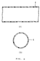
- Fig. 3 shows cross-sectional views of a seamless polyimide tube of another example in longitudinal direction (a) and diameter direction (b).
- Fig. 4 shows a cross-sectional view of a deposition mechanism of an electronic photo apparatus using a polyimide tube of another example.
- thermosetting and heat reversible but has high heat-resistant temperature and melting point such as polyimide resin, polyamideimide resin, aromatic polyester resin, polyethersulfone resin, polyesterimide resin, polyimidazopyrrolone resin, polyparabanic acid resin, and bismaleimidetriazine resin. Since these heat-resistant resins can hardly be transformed and molded as a tube with a uniform thin tube wall thickness in a melted condition, intermediates or precursers of heat-resistant resins, which are treated with solvents or the like to form a gel or varnish before the drying, hardening and reacting steps, can be used for molding the tubes instead.
- intermediates or precursors include the intermediate created by the reaction of aromatic tetracarboxylic acid anhydride (polyamide acid), the intermediate of polymellitic acid anhydride and aromatic diamime, polyesterimide intermediate, polyethersulfone intermediate, aromatic diamine acid ester resin intermediate, bismaleimidetriazine resin intermediate, polybenzoimidazole intermediate, polyparabanic acid intermediate or the like.
- Metallic materials such as stainless steel, aluminum, iron or the like with plated surface, glass pipes and rods, and the like can be used as a core material.
- the surface of the core material is cut, scraped or molded to have a preferable surface condition for an inside tube surface.
- a material for easily separating the tube from the core can be applied to the core surface.
- silicone or fluororesin which can tolerate the temperature during the process of heat treatment, can be applied to the core.
- the core is then dipped and lifted from a material such as the precursor solution of polyimide resin, and the solution is coated on the surface of the core.
- a material such as the precursor solution of polyimide resin
- the thickness of the coated precursor solution around the core is irregular.
- Methods of adhering the polyimide resin precursor solution to the core include a method of pouring the solution on the core, a method of applying the solution to the core with a brush and the like.
- the metallic die is located on the top edge of the core while the distance between the die and the core is kept at the desired tube wall thickness; the metallic die is dropped along the core by its own weight.
- the dropping speed of the die depends on the viscosity of the precursor solution and the weight of the die.
- the dropping speed of the die is an important factor in determining the uniformity of the tube wall thickness. For example, under the conditions of high viscosity of the precursor solution of a tube material, short distance between the core surface and the inside surface of the metallic die, and light weight of the die, the dropping speed of the die along the core becomes extremely slow, thus providing a tube with an uneven tube wall thickness. On the other hand, when the viscosity of the precursor solution is low or the distance between the inside surface of the die and the core surface is extremely wide, the die drops along the core without much resistance from the solution, thereby providing a tube with the wall thickness favoring one side.
- the uniformity of the tube wall thickness depends on many factors such as the thickness of the precursor solution on the core, the core diameter, the weight of the core, the shape of the core, etc.
- a tube with uniform wall thickness can be obtained with a 2-210mm/sec dropping speed of the mold. This can be achieved by a method of fixing the metallic die with or without some flexibility and pulling the core with a string, thread and the like at 2-210 mm/sec. This method can be applied even when the core is extremely thin and prone to bending (for example, wire).
- a method of dropping the core through the metallic die fixed with or without some flexibility is also applicable to the invention.
- the viscosity of the precursor solution is 50-10000 poise.
- the passing speed of the die tends to be too fast when the viscosity is less than 50 poise, thus providing a tube with an uneven tube wall thickness. It is also difficult to provide a tube with even tube wall thickness if the viscosity is greater than 10000 poise.
- Fig. 1 shows a cross-sectional view of one example of a manufacturing method using a core 1 and a metallic die 2.
- Core 1 is dipped in a polyimide resin precursor solution 3 inside a vessel 5.
- metallic die 2 is placed at a certain distance from core 1.
- a polyimide resin precursor tube 4 is formed around core 1 with a uniform tube wall thickness.
- the solvent is removed from polyimide resin precursor tube 4 by drying the tube around core 1, thus making the tube dense.
- the tube is separated from core 1, thus providing a seamless tube 6.
- Fig. 2 shows a cross-sectional view of metallic die 2.
- Fig. 3 (a) shows a cross-sectional view of seamless tube 6 in a longitudinal direction
- Fig. 3 (b) shows a cross-sectional view of the tube in a diameter direction.
- the following tables 1, 2 and 3 show the correlation between tube wall thickness and the speed of passing a die along a core, the correlation between tube wall thickness and the viscosity of a precursor solution of a tube material, and the correlation between the diameter of a core and the speed of passing a die along the core.
- o ⁇ in the tables indicates the most preferable results; ⁇ indicates adequate characteristics of a tube.
- the precursor solution of a tube material After adhering the precursor solution of a tube material to the surface of the core, the precursor solution is dried naturally or with heat, hardened, and reacted, and then its solvent is extracted, etc., and the solution is held on the core until it reaches the stage of maintaining its strength as a tube.
- the polyimide resin precursor tube around the core should be heated and dried at 120-200°C, thus removing the solvent contained in the polyimide resin precursor tube and obtaining strength as a tube.
- the tube After reacting the tube to form an imide to some extent or thoroughly by heating or the like, the tube is forcibly separated from the core.
- the outside surface of the tube has a natural surface condition since it is molded in contact with the air; the inside surface of the tube reflects the condition of the core surface. By imparting particular surface conditions to the core, the inside surface condition of the tube can be controlled.
- a polyimide seamless tube of the invention can be used for, as an example, an electronic photo deposition apparatus of Fig. 4. More specifically, the deposition apparatus is composed of a drive roll 7, a tension roll 8 and a heater 9 provided inside a polyimide tube 6 and a back-up roll 10 provided outside thin polyimide tube 6. The deposition apparatus has a mechanism for supplying copying paper 11 formed with toner 12 between polyimide tube 6 and back-up roller 10, and constantly depositing toner by heating copying paper 11 with heater 9, thus providing fixed image 13.
- Polyimide resin precursor solution used in the invention is prepared, for example, by reacting aromatic tetracarboxylic acid with aromatic diamime in an organic polar solvent.
- aromatic tetracarboxylic acid for instance, 3, 3', 4, 4'-biphenyltetracarboxylic acid di-anhydride; 2, 3', 4, 4'-benzophenonetetracarboxylic acid di-anhydride; pyromellitic acid di-anhydride; or a mix of these tetracarboxylic acids can be used as aromatic tetracarboxylic acid.
- the aromatic tetracarboxylic acid is not limited to these acids.
- Aromatic diamimes include, diphenylether diamimes such as 3, 3'-diaminophenylether, 3, 3'-dimethoxy-4, 4'-diaminodiphenylether, 4, 4'-diaminophenylether and the like; diphenylthioether diamimes such as 3, 3'-diphenylthioether, 4, 4'-diaminodiphenylthioether and the like; benzophenone diamimes such as 4, 4'-diaminobenzopheneo and the like; diphenylmethane diamine; paraphenylene diamine; m-phenylenediamime and the like can be included; and the aromatic diamine is not restricted to these diamines.
- diphenylether diamimes such as 3, 3'-diaminophenylether, 3, 3'-dimethoxy-4, 4'-diaminodiphenylether, 4, 4'-diaminophenylether
- N-methyl-2-pyrolidone, dimethylformamide, dimethylacetamide, phenol, o-cresol, m-cresol, p-cresol, dimethloxide and the like are examples of suitable organic polar solvents.
- the organic polar solvent is not limited to these solvents.
- the presursor solution of polyimidazopyrrolone which is prepared by reacting diaminobenzidine with pyromellitic acid anhydride solution can also provide a uniform tube wall thickness.
- Fig. 1 The manufacturing method illustrated in Fig. 1 was used in this example.
- a stainless steel rod 40mm in outside diameter and 1000mm long was treated to have a satin finished surface, and this surface was thinly coated with silicone oil and dried, thus providing the core of this example.
- Polyimide resin precursor solution was prepared by reacting 3, 3', 4, 4'-biphenyl tetracarboxylic acid di-anhydride having 1000 poise viscosity with aromatic diamime in N-methyl-2-pyrolidone.
- the core was dipped and held in the prepared polyimide resin precursor solution up to 800mm.
- an aluminum ring 40.5mm in inside diameter, 45° in liquid contact angle (Fig. 2: ⁇ ), 665g in weight and 3mm in land length (Fig. 2: L) slid down along the core by its own weight.
- the ring dropped rapidly at the beginning of the sliding process, the sliding speed soon became constant due to the resistant force of viscosity of polyimide resin precursor solution.
- the sliding speed of the outside ring was 7.2mm/sec. When the ring reached the bottom of the core, it was removed from the core. The core was then dried in a furnace at 120°C for 30 minutes, at 200°C for 20 minutes, at 300°C for 60 minutes and then 350°C for 60 minutes, thus letting the polyimide resin precursor become imide. The core was taken out from the furnace and cooled in the air. After checking whether or not the coated polyimide resin precursor solution sags down or sticks to fingers, the coated material was separated from the core carefully, thus providing a tube with a uniform tube wall thickness except the top and bottom 3cm edges. The tube wall thickness was 22 ⁇ m ⁇ 1 ⁇ m, and the circumference of the tube was 40mm ⁇ 2% of diameter. The difference in circumference at the bottom, center and top side of the tube was within 1%.
- a chart showing the surface roughness of the inside tube surface indicates a satin finished surface, which is exactly the same as the surface condition of the core. According to the measurement of JIS B0601, the fineness (Rz) of the outside tube surface was less than 1 ⁇ m since the surface was molded in contact with the air.
- Example 2 Under the same conditions as Example 1, the core was dipped and held in a tank containing polyimide precursor solution after setting a metallic ring above the core at a fixed distance between the core and the inside diameter of the ring. The core coated with polyimide precursor solution was mechanically passed through the ring at 20mm/sec. As a result, a polyimide precursor tube was molded around the core with a tube wall thickness of 500 ⁇ m. Then, the ring was removed from the core.
- Example 2 Under the same conditions as Example 1, the tube was heated and reacted to form the imide completely.
- the average tube wall thickness was 42 ⁇ m, and the difference between the thickest tube wall thickness and the thinnest tube wall thickness was 16 ⁇ m.
- the procedures applied in this example were tested many times, and the test results were various Notably, thin parts of the tubes had unnatural concave and convex surfaces. Because of these reasons, the tubes did not meet the criteria for a desirable tube.
- Example 2 The same procedures of Example 1 were directed in this example, except that the weight of an aluminum ring was changed to 2025g. Polyimide precursor solution was adhered to the surface of the core. The ring with 40.5mm in inside diameter, 2025g in weight and 45° in liquid contact angle (Fig. 2: ⁇ ) was set on the top edge of the core. As the ring slid down along the core, it lost its parallelism. Without being balanced with the resistance force of the polyimide precursor solution, the core dropped rapidly, and a tube with an uneven tube wall thickness was provided.
- a polished cylindrical stainless steel pipe 40mm in outside diameter, 20mm in inside diameter and 1m long, and a cylindrical stainless steel rod 19.5mm in diameter and 30mm long were prepared. One edge of the rod was curved conically 5°.
- the silicone diluent solution of Example 1 was sprayed inside the pipe. Then, the rod was dropped into the pipe by its own weight, but the rod ceased dropping without reaching the bottom of the pipe. The rod weighed about 75g and was estimated to be too light to reach the bottom.
- a rod 240mm in length and about 600g in weight was then dropped from the top side of the pipe. However, again, the rod did not go through the pipe, and no tube was provided in this example.
- Example 1 The same metallic die, core and precursor solution of Example 1 were used in this example. However, unlike in Example 1, a string was attached to the center of the top side of the core while the die was fixed in this example. The core, coated with the precursor solution, was lifted from below through the die at a constant speed by pulling the string. The core was flexibile enough to be controlled and managed to keep its parallelism due to the precursor solution. The lifting speed of the core was 7.2mm/sec. Then, the same treatments of Example 1 were directed to the solution coated on the core, thus providing a tube with uniform tube wall thickness. The tube of this example was exactly the same as the tube of Example 1.
- Example 1 The same procedures of Example 1 were directed in this example, except that the viscosity of the polyimide precursor was raised to 20000 poise. Since the metallic die did not slide on the outside core, a tube was not provided in this example.
- a glass rod 10mm in outside diameter and 2m long, and an outside metallic ring 10.8mm in inside diameter and 5000g in weight were prepared.
- a precursor solution of bismaleimidetriazine resin having 500 poise viscosity was prepared by reacting bismaleimide with cyanic acid ester solution. The precursor solution was then applied to the glass rod. The metallic die slid from the top of the rod at 198mm/sec. The solution coated around the core was heated and hardened at 300°C for three hours, and was separated from the glass rod, thus providing a tube. 50mm of each top and bottom edge of the tube were cut off, and a tube about 1.8m in length was provided.
- the tube had an inside diameter of 10mm and was 53 ⁇ m ⁇ 2% in thickness, and was a seamless tube with a uniform tube wall thickness.
- the surface roughness of the outside surface and inside surface of the tube was measured. Since the glass rod was used as the core, the inside surface of the tube was extremely smooth. More specifically, Rz of the outside surface was less than 1 ⁇ m while Rz of the inside surface was less than 1.5 ⁇ m.
- the surface of an aluminum core 180mm in outside diameter and 500mm long was roughened slightly by a sand blasting method. Then, polytetrafluoroethylene resin was applied to the aluminum core, thus providing the core for this example.
- the surface roughness of the core was Rz 3.0 ⁇ m.
- the top side of the core was attached to three wires, and the core was lifted in the air.
- Polyimide precursor solution was prepared by reacting 3.3', 4.4'-biphenyl tetracarboxylic acid anhydride with aromatic diamime in N-methyl-2-pyrolidone.
- the core surface was coated at about 1mm or more in thickness and 430mm in length with the polyimide precursor solution by using a brush.
- An aluminum die 181mm in inside diameter, 1050g in weight and 30° in liquid contact angle (Fig. 2: ⁇ ) was dropped from the top of the core. Due to the resistant force of the polyimide precursor solution, the aluminum die was balanced, and slid along the core by its own weight.
- the tube was formed around the core while the parallelism and eccentricity between the core and the die was naturally adjusted without restricting both the core and the ring.
- the tube wall thickness was 0.5mm.
- the average sliding speed of the die was 10.0mm/sec.
- the tube around the core was then heated at 150°C for 80 minutes and at 230°C for 30 minutes, thus forming the tube into an imide.
- the tube was cooled, and was separated from the core. As a result, a tube with 180mm in inside diameter and 300mm long was provided in this example.
- the tube was then put on a stainless steel core 180mm in outside diameter.
- the surface of the tube was coated with a copolymer in a mixed solution in which tetrafluoroethylene resin and tetrafluoroethylene parfluoroalkylvinylether are mixed, and was dried.
- the tube was heated at 300°C for 40 minutes and at 400°C for 50 minutes, and then was cooled down to room temperature.
- the tube was separated from the core, thus providing a polyimide tube coated with fluororesin on its surface.
- the tube wall thickness was 45 ⁇ m, and uneveness in the thickness was ⁇ 2.3 ⁇ m.
- the length of the tube within the range of ⁇ 2.3 ⁇ m uneven tube wall thickness was 380mm.
- the outside surface roughness of the tube was Rz 0.2 ⁇ m, and the inside surface roughness was Rz 2.8-3.0 ⁇ m.
- the film When the tube of this example was used for a copier picture processing film, the film exhibited a high performance.
- the coated precursor material of a heat-resistant resin is heated, dried naturally, and hardened by heat, then its solvent is extracted, and the like, thus maintaining its strength as a tube.
- the coated precursor material is then separated from the core, thereby providing a tube with a uniform tube wall thickness and circumference.
Landscapes
- Engineering & Computer Science (AREA)
- Mechanical Engineering (AREA)
- Moulding By Coating Moulds (AREA)
Claims (10)
- Procédé de fabrication d'un tube résineux résistant à la chaleur, comprenant les étapes consistant :à déposer une solution de précurseur d'une résine résistante à la chaleur, sur la surface d'une âme ayant une épaisseur supérieure à l'épaisseur de paroi de tube dudit tube résineux résistant à la chaleur ;à préparer une filière métallique ayant un diamètre intérieur supérieur au diamètre de ladite âme ;à faire passer ladite filière métallique le long de l'extérieur de ladite âme pour former un tube autour de ladite âme ;à traiter ledit tube sur ladite âme pour conférer une certaine résistance audit tube résineux résistant à la chaleur ; età séparer ledit tube de ladite âme, caractérisé en ce qu'on utilise la force de résistance de ladite solution de précurseur, sans étranglement de ladite filière métallique et/ou de ladite âme, lorsque l'on fait passer la filière le long de l'extérieur de l'âme.
- Procédé selon la revendication 1, caractérisé en ce que la viscosité de la solution de précurseur ainsi que le poids de la filière métallique et de l'âme, sont ajustés de façon à maintenir une vitesse de passage de la filière métallique le long de l'extérieur de l'âme, de 2 mm/s à 210 mm/s.
- Procédé selon la revendication 1 ou 2, caractérisé en ce que la filière métallique passe de son propre poids le long de l'extérieur de l'âme.
- Procédé selon l'une quelconque des revendications 1 à 3, caractérisé en ce que la solution de précurseur, comprend au moins une solution choisie parmi une solution de précurseur de résine de polyimide, une solution de précurseur de résine de polyamideimide, une solution de précurseur de résine de polyester aromatique, une solution de précurseur de résine de polyéthersulfone, une solution de précurseur de résine de polyestérimide, une solution de précurseur de résine d'acide polyparabanique, une solution de précurseur de résine de polyimidazopyrrolone et une solution de précurseur de résine de bismaléimidetriazine.
- Procédé selon l'une quelconque des revendications 1 à 4, caractérisé en ce que la solution de précurseur comprend au moins un polymère choisi parmi un monomère générateur de polyimide et un oligomère générateur de polyimide.
- Procédé selon l'une quelconque des revendications 1 à 5, caractérisé en ce que la viscosité de la solution de précurseur est de 50 poises à 10 000 poises.
- Procédé selon l'une quelconque des revendications 1 à 6, caractérisé en ce que le traitement destiné à conférer une certaine résistance au tube, est un traitement de chauffage.
- Procédé selon l'une quelconque des revendications 1 à 7, caractérisé en ce que la température est accrue par paliers dans le traitement de chauffage.
- Procédé selon l'une quelconque des revendications 1 à 8, caractérisé en ce que l'épaisseur de paroi de tube du tube résineux résistant à la chaleur, est de 3 µm à 300 µm.
- Procédé selon l'une quelconque des revendications 1 à 9, caractérisé en ce que la surface extérieure du tube résineux résistant à la chaleur est conditionnée par l'air, et dans lequel l'état de surface intérieure du tube résineux résistant à la chaleur, correspond à l'état de surface de l'âme.
Priority Applications (3)
| Application Number | Priority Date | Filing Date | Title |
|---|---|---|---|
| DE1993619735 DE69319735T2 (de) | 1993-10-29 | 1993-10-29 | Verfahren zur Herstellung eines hitzebeständigen Rohres aus Kunststoff |
| EP93117593A EP0650823B1 (fr) | 1993-10-29 | 1993-10-29 | Procédé pour la fabrication d'un tube en polymère, résistant à la chaleur |
| US08/155,151 US5433913A (en) | 1993-10-29 | 1993-11-19 | Method of manufacturing a heat-resistant resinous tube |
Applications Claiming Priority (2)
| Application Number | Priority Date | Filing Date | Title |
|---|---|---|---|
| EP93117593A EP0650823B1 (fr) | 1993-10-29 | 1993-10-29 | Procédé pour la fabrication d'un tube en polymère, résistant à la chaleur |
| US08/155,151 US5433913A (en) | 1993-10-29 | 1993-11-19 | Method of manufacturing a heat-resistant resinous tube |
Publications (2)
| Publication Number | Publication Date |
|---|---|
| EP0650823A1 EP0650823A1 (fr) | 1995-05-03 |
| EP0650823B1 true EP0650823B1 (fr) | 1998-07-15 |
Family
ID=26133494
Family Applications (1)
| Application Number | Title | Priority Date | Filing Date |
|---|---|---|---|
| EP93117593A Expired - Lifetime EP0650823B1 (fr) | 1993-10-29 | 1993-10-29 | Procédé pour la fabrication d'un tube en polymère, résistant à la chaleur |
Country Status (2)
| Country | Link |
|---|---|
| US (1) | US5433913A (fr) |
| EP (1) | EP0650823B1 (fr) |
Families Citing this family (13)
| Publication number | Priority date | Publication date | Assignee | Title |
|---|---|---|---|---|
| JP3054010B2 (ja) * | 1993-11-15 | 2000-06-19 | 株式会社アイ.エス.テイ | ポリイミド複合管状物とその製造方法及び製造装置 |
| US5846645A (en) * | 1995-03-03 | 1998-12-08 | Asahi Glass Company Ltd. | Fluorocarbon resin-coated product |
| JP3990467B2 (ja) * | 1995-09-26 | 2007-10-10 | 住友電気工業株式会社 | 管状物の製造方法及び管状物 |
| US6500375B1 (en) | 2000-03-06 | 2002-12-31 | Lexmark International Inc. | Fabrication of seamless tube |
| JP3667661B2 (ja) * | 2001-06-05 | 2005-07-06 | 昭和電線電纜株式会社 | ポリイミドスリーブの製造方法 |
| US20030191355A1 (en) * | 2002-04-04 | 2003-10-09 | Ferguson Patrick J. | Hollow bioabsorbable elements for positioning material in living tissue |
| US7459027B2 (en) * | 2003-12-24 | 2008-12-02 | Eastman Kodak Company | Pneumatically adjustable apparatus for coating toner fusing belt substrate and method for using same |
| JP5216245B2 (ja) * | 2007-06-01 | 2013-06-19 | 株式会社日立製作所 | 記憶システム、記憶制御装置及びデータ圧縮方法 |
| WO2009018313A1 (fr) * | 2007-07-30 | 2009-02-05 | Atrium Medical Corporation | Réduction d'un gabarit avec revêtement d'un réceptacle contenant un dispositif médical à revêtir |
| US7658876B2 (en) * | 2008-02-08 | 2010-02-09 | Lexmark International, Inc. | Method to fabricate a seamless tube |
| EP2837611A4 (fr) * | 2012-03-29 | 2015-11-25 | Ibiden Co Ltd | Gabarit d'application et procédé de fabrication d'un corps à structure en nid d'abeilles |
| CN103817042B (zh) * | 2014-02-28 | 2015-11-18 | 宁波保税区安杰脉德医疗器械有限公司 | 一种用于高分子导管表面的涂层设备 |
| CN106182536B (zh) * | 2016-07-06 | 2018-10-02 | 河南驼人医疗器械集团有限公司 | 一种可变径的抗折压型气管插管的制作工艺 |
Family Cites Families (17)
| Publication number | Priority date | Publication date | Assignee | Title |
|---|---|---|---|---|
| DE881625C (de) * | 1951-04-11 | 1953-07-02 | Siemens Ag | Abstreifer fuer UEberzuege aus fluessigen Stoffen auf langgestreckten Formstraengen |
| US3502762A (en) * | 1967-01-24 | 1970-03-24 | Minnesota Mining & Mfg | Method of making polyimide film |
| US3600361A (en) * | 1969-06-11 | 1971-08-17 | Du Pont | Process for drying polyamide-acid/imide film |
| GB1344475A (en) * | 1971-03-19 | 1974-01-23 | Ici Ltd | Method and device for coating plastics film |
| IT1061373B (it) * | 1976-05-18 | 1983-02-28 | Bonfanti Ottavio | Procedimento per la produzione di materiale sintetico di aspetto madreperlaceo apparecchiatura per attuare tale procedimento e materiali cosi ottenuti |
| JPS601888B2 (ja) * | 1980-02-25 | 1985-01-18 | 日東電工株式会社 | ポリイミドチュ−ブ類の製造法 |
| JPS6219437A (ja) * | 1985-07-19 | 1987-01-28 | Nitto Electric Ind Co Ltd | ポリイミド管状物の製造法 |
| GB8710833D0 (en) * | 1987-05-07 | 1987-06-10 | Porous Plastics Ltd | Microwave heating |
| US5116551A (en) * | 1987-05-07 | 1992-05-26 | Davidson Roderick I | Method and apparatus for producing an article by microwave heating |
| JPH01156017A (ja) * | 1987-12-15 | 1989-06-19 | Nitto Denko Corp | ポリイミド複層管状物の製造方法 |
| US4898702A (en) * | 1988-04-04 | 1990-02-06 | Cordis Corporation | Method and apparatus for removal of a wire mandrel from a catheter |
| US4863668A (en) * | 1988-09-22 | 1989-09-05 | University Of Utah | Method of forming fibrin-collagen nerve and body tissue repair material |
| JP3103084B2 (ja) * | 1989-12-08 | 2000-10-23 | 株式会社アイ.エス.テイ | 管状物の製造方法 |
| JP2912922B2 (ja) * | 1990-03-09 | 1999-06-28 | 株式会社アイ.エス.ティ | 管状物の製造方法 |
| JPH0734885B2 (ja) * | 1990-04-16 | 1995-04-19 | 横浜ゴム株式会社 | ホース製造工程における接着剤塗布方法及び接着剤塗布装置 |
| US5176666A (en) * | 1990-11-09 | 1993-01-05 | Rochester Medical Corporation | External urinary catheter having integral adhesive means |
| WO1992008426A1 (fr) * | 1990-11-09 | 1992-05-29 | Rochester Medical Corporation | Catheter externe pour l'urine comprenant un systeme de fixation incorpore |
-
1993
- 1993-10-29 EP EP93117593A patent/EP0650823B1/fr not_active Expired - Lifetime
- 1993-11-19 US US08/155,151 patent/US5433913A/en not_active Expired - Lifetime
Also Published As
| Publication number | Publication date |
|---|---|
| EP0650823A1 (fr) | 1995-05-03 |
| US5433913A (en) | 1995-07-18 |
Similar Documents
| Publication | Publication Date | Title |
|---|---|---|
| EP0650823B1 (fr) | Procédé pour la fabrication d'un tube en polymère, résistant à la chaleur | |
| EP0653297B1 (fr) | Tuyau composite en polyimide et procédé pour sa fabrication | |
| US6090326A (en) | Tubular object manufacturing method | |
| JP3305121B2 (ja) | ポリイミド管状物の製造方法及び製造装置 | |
| JP3305467B2 (ja) | シームレス樹脂フィルム及びその製造方法 | |
| JP3238811B2 (ja) | ポリイミド管状物の製造方法及び製造装置 | |
| JP3667661B2 (ja) | ポリイミドスリーブの製造方法 | |
| JP3193694B2 (ja) | 管状物の製造方法 | |
| JP4798853B2 (ja) | シームレスベルト及びその製造方法 | |
| JP3012403B2 (ja) | 管状物の製造方法 | |
| JPH10138264A (ja) | 複合フィルムの製造方法 | |
| JP4044471B2 (ja) | 管状物の製造方法とこれに用いるキャスト成型装置 | |
| JP2002018872A (ja) | 高精度管状体の製造方法 | |
| JP3122286B2 (ja) | 管状物の製造方法 | |
| JPH01139228A (ja) | 管状物の製造方法 | |
| JP3011204B1 (ja) | 管状物の製造方法 | |
| JPH11198158A (ja) | ポリイミド管状物の製造型及び製造方法 | |
| WO2001085418A1 (fr) | Procede de fabrication de bandes de polyimide sans joints | |
| JP4045818B2 (ja) | ポリイミド樹脂無端ベルト、及びその製造方法 | |
| JP2002264151A (ja) | 高精度管状体の製造方法及び高精度管状体 | |
| JP2002283364A (ja) | シームレスベルトの製造方法およびシームレスベルト用金型 | |
| JP3707113B2 (ja) | ポリイミド管状物の製造方法 | |
| JPH03110137A (ja) | 変形管状物およびその製法 | |
| JP2009098261A (ja) | 環状シームレスベルトおよびその製造方法 | |
| JPH026876A (ja) | 静電記録用シームレスベルトの製造方法 |
Legal Events
| Date | Code | Title | Description |
|---|---|---|---|
| PUAI | Public reference made under article 153(3) epc to a published international application that has entered the european phase |
Free format text: ORIGINAL CODE: 0009012 |
|
| AK | Designated contracting states |
Kind code of ref document: A1 Designated state(s): DE FR GB IT NL |
|
| 17P | Request for examination filed |
Effective date: 19951017 |
|
| 17Q | First examination report despatched |
Effective date: 19961104 |
|
| GRAG | Despatch of communication of intention to grant |
Free format text: ORIGINAL CODE: EPIDOS AGRA |
|
| GRAG | Despatch of communication of intention to grant |
Free format text: ORIGINAL CODE: EPIDOS AGRA |
|
| GRAH | Despatch of communication of intention to grant a patent |
Free format text: ORIGINAL CODE: EPIDOS IGRA |
|
| GRAH | Despatch of communication of intention to grant a patent |
Free format text: ORIGINAL CODE: EPIDOS IGRA |
|
| RAP3 | Party data changed (applicant data changed or rights of an application transferred) |
Owner name: I.S.T. CORPORATION |
|
| GRAA | (expected) grant |
Free format text: ORIGINAL CODE: 0009210 |
|
| AK | Designated contracting states |
Kind code of ref document: B1 Designated state(s): DE FR GB IT NL |
|
| REF | Corresponds to: |
Ref document number: 69319735 Country of ref document: DE Date of ref document: 19980820 |
|
| ET | Fr: translation filed | ||
| PLBE | No opposition filed within time limit |
Free format text: ORIGINAL CODE: 0009261 |
|
| STAA | Information on the status of an ep patent application or granted ep patent |
Free format text: STATUS: NO OPPOSITION FILED WITHIN TIME LIMIT |
|
| 26N | No opposition filed | ||
| REG | Reference to a national code |
Ref country code: GB Ref legal event code: IF02 |
|
| PGFP | Annual fee paid to national office [announced via postgrant information from national office to epo] |
Ref country code: DE Payment date: 20101022 Year of fee payment: 18 |
|
| PGFP | Annual fee paid to national office [announced via postgrant information from national office to epo] |
Ref country code: GB Payment date: 20101021 Year of fee payment: 18 Ref country code: IT Payment date: 20101026 Year of fee payment: 18 |
|
| PGFP | Annual fee paid to national office [announced via postgrant information from national office to epo] |
Ref country code: NL Payment date: 20111025 Year of fee payment: 19 Ref country code: FR Payment date: 20111103 Year of fee payment: 19 |
|
| REG | Reference to a national code |
Ref country code: NL Ref legal event code: V1 Effective date: 20130501 |
|
| GBPC | Gb: european patent ceased through non-payment of renewal fee |
Effective date: 20121029 |
|
| REG | Reference to a national code |
Ref country code: FR Ref legal event code: ST Effective date: 20130628 |
|
| PG25 | Lapsed in a contracting state [announced via postgrant information from national office to epo] |
Ref country code: DE Free format text: LAPSE BECAUSE OF NON-PAYMENT OF DUE FEES Effective date: 20130501 Ref country code: GB Free format text: LAPSE BECAUSE OF NON-PAYMENT OF DUE FEES Effective date: 20121029 |
|
| REG | Reference to a national code |
Ref country code: DE Ref legal event code: R119 Ref document number: 69319735 Country of ref document: DE Effective date: 20130501 |
|
| PG25 | Lapsed in a contracting state [announced via postgrant information from national office to epo] |
Ref country code: NL Free format text: LAPSE BECAUSE OF NON-PAYMENT OF DUE FEES Effective date: 20130501 Ref country code: FR Free format text: LAPSE BECAUSE OF NON-PAYMENT OF DUE FEES Effective date: 20121031 Ref country code: IT Free format text: LAPSE BECAUSE OF NON-PAYMENT OF DUE FEES Effective date: 20121029 |