EP0647495B1 - Welding deformation reducing method for one-side strap joint welding - Google Patents
Welding deformation reducing method for one-side strap joint welding Download PDFInfo
- Publication number
- EP0647495B1 EP0647495B1 EP94905844A EP94905844A EP0647495B1 EP 0647495 B1 EP0647495 B1 EP 0647495B1 EP 94905844 A EP94905844 A EP 94905844A EP 94905844 A EP94905844 A EP 94905844A EP 0647495 B1 EP0647495 B1 EP 0647495B1
- Authority
- EP
- European Patent Office
- Prior art keywords
- welding
- welded
- electrode
- deformation
- groove
- Prior art date
- Legal status (The legal status is an assumption and is not a legal conclusion. Google has not performed a legal analysis and makes no representation as to the accuracy of the status listed.)
- Expired - Lifetime
Links
Images


Classifications
-
- B—PERFORMING OPERATIONS; TRANSPORTING
- B23—MACHINE TOOLS; METAL-WORKING NOT OTHERWISE PROVIDED FOR
- B23K—SOLDERING OR UNSOLDERING; WELDING; CLADDING OR PLATING BY SOLDERING OR WELDING; CUTTING BY APPLYING HEAT LOCALLY, e.g. FLAME CUTTING; WORKING BY LASER BEAM
- B23K9/00—Arc welding or cutting
- B23K9/095—Monitoring or automatic control of welding parameters
- B23K9/0953—Monitoring or automatic control of welding parameters using computing means
Definitions
- the present invention relates to a method of reducing welding distortion in one side welding for joining plates. More particularly, the present invention provides a method of reducing welding distortion in one side welding for joining plates, by which welding distortion is reduced when welding is executed under optimal welding conditions in multi-electrode welding.
- the following one side welding methods for joining plates are provided.
- steel plates 1, 1' to be welded are butted against each other, and a tack-welded bead, the height of which is the same as the wall thickness of the plates to be welded, is provided in a groove, especially in a groove of the end portion of welding.
- a tab the thickness of which is the same as the wall thickness of the plates to be welded, is tack-welded at the end portion of welding so that the height of the bead can be the same as the wall thickness.
- the steel plates 1, 1' to be welded are sufficiently bound before the start of welding so as to reduce welding distortion.
- the following method in which the plates to be welded are heated by means of gas burners in the process of welding, so that the thermal history is controlled for reducing welding distortion.
- a high restraining force is applied to the steel plates to be welded using the tack-welded bead or tab, a heavy burden is imposed for preparation before the start of welding, and further it is necessary to repair the plates after the completion of welding, which causes a problem from the viewpoint of enhancing the efficiency of welding.
- the method of controlling the thermal history using gas burners is disadvantageous in that the welding apparatus becomes large and it is difficult to enhance the welding efficiency.
- Japanese Unexamined Patent Publication No. 53-51153 discloses a method in which an amount of welding heat input is reduced at the end portion of plates to be welded and an amount of bead is supplied to make up for the lacking bead in the process of repairing work.
- the conventional techniques primarily aim at restraining the steel plates to be welded or controlling the thermal history with gas burners.
- the conventional techniques do not aim at a welding condition of one side welding for joining plates. Therefore, according to the prior art, it is natural that a heavy burden is imposed on the process of welding, and the welding apparatus becomes large.
- the present invention has been achieved in order to reduce a heavy burden imposed on the preparation work of welding and also to reduce a heavy burden imposed on the welding apparatus.
- the present invention is accomplished when a welding condition is found, by which the occurrence of welding deformation can be reduced.
- the present invention is intended to provide a method of reducing welding distortion in one side welding for joining plates, wherein the method is based on the welding condition described above.
- a preferred embodiment of the invention comprises applying a value of Ptab which is calculated by the following expression (3) to be not less than 0.009 for tack-welding and fixing at the end portion of the steel plates to be welded:
- the invention is carried out in submerged arc welding under the welding condition that: a current of each electrode is not more than 2400 A; currents of the first and second electrodes are not less than 900 A; currents of the third electrode and after that are not less than 600 A; a welding speed is not less than 1 cm/s and not more than 3.33 cm/s; and a bonded type flux is used at the surface and the back.
- the groove may be a Y-groove, I-groove, V-groove or U-groove.
- the tensile strength of steel plates to be joined should be not less than 390 Mpa and not more than 780 Mpa, and the wall thickness not less than 8 mm and not more than 50 mm.
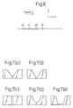
- Fig. 6 is a schematic illustration showing a model of the present invention.
- Numerals 19, 20, 21 and 22 respectively represent the first, second, third and fourth electrodes. It is assumed that these electrodes are moving on an infinite flat plate from the left to right in Fig. 6. Concerning the coordinate, the first electrode is determined as an origin, and a moving coordinate ( ⁇ , y) is set which moves at the same speed V as the welding speed.
- Fig. 6 shows a condition of 4 electrode welding, the following analysis is made under the condition that the number of electrodes is n.
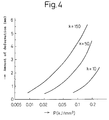
- Fig. 4 shows that the parameter P corresponds to an amount of deformation.
- the horizontal axis in Fig. 4 expresses an amount of deformation caused during the welding operation in an example described later. Therefore, it can be understood that the parameter P is in a good correlation with the amount of deformation caused during the welding operation. Due to the foregoing, when the value P is suppressed in a predetermined range, an amount of deformation can be reduced.
- the parameter Ptab used for the tab has the same relation as that of the tack-welded bead described above.
- the tab restrains the steel plates to be welded in the same manner as the tack-welded bead. Therefore, it is possible to evaluate the function of the tab in the same manner.
- the parameter P is divided into the two terms of ⁇ Qi/(Li+k) and 1/H, and each term is described as follows.
- Term ⁇ Qi/(Li+k) in the parameter P expresses how the welding condition affects an amount of welding deformation. Normally, when the welding heat input is reduced, an amount of welding deformation tends to be reduced. However, in the case of one side welding for joining steel plates, the joining must be completed by one welding operation, so that the heat input cannot be extremely reduced. Configuration of the melting pool in the case of one-electrode welding and that of the melting pool in the case of multi-electrode welding are different. Accordingly, even when the heat input is the same, the welding deformation behavior is different. Therefore, in order to determine the welding condition so that the welding deformation can be reduced, it is necessary to adopt a parameter expressing the configuration of a melting pool or a parameter expressing the arrangement of electrodes.
- H is the maximum of the height of the tack-welded bead provided in a butted groove.
- a parameter to find a relation between the welding deformation behavior and the welding condition can be described by Qi and Li.
- the steel plates to be welded are not subjected to tack welding at all, that is, when a tack-welded bead is not formed in the groove at all and the steel plates to be welded are not restrained by a tab, the steel plates to be welded are not restrained at all. In this case, even when a welding condition to reduce an amount of welding deformation is adopted, it is substantially impossible to conduct welding. Consequently, it is essentially necessary to restrain the steel plates by a minimum amount of tack-welded bead. Therefore, it is necessary to find a parameter expressing this influence.
- the inventors have also investigated the influence of H from the above viewpoint and found the following:
- H is the maximum height of the tack-welded bead in the butted groove
- the welding deformation can be most restricted at a position where the bead height is maximum. Therefore, the most effective means is to employ the maximum value H.
- the parameter Ptab is provided when H is replaced with Ht in the parameter P. It is an object of the present invention to reduce an amount of welding deformation mainly by selecting a welding condition.
- a tab is used not only for the purpose of reducing an amount of welding deformation but also for accomplishing another object.
- using a tab is an effective means in the industrial field for preventing the occurrence of a crater at the end portion of welding on the steel plates to be welded.
- this tab works to restrain the steel plates to welded. Consequently, the inventors have given consideration to the case in which the steel plates to be welded are restrained by the tab.
- the inventors have found the following: Ptab is a parameter for expressing the influence of the tab and welding condition on the welding deformation, and in the same manner as P, the parameter Ptab expresses the influence of the tab.
- a method of selecting an appropriate welding condition In order to set the parameters P and Ptab in a predetermined range, there are three methods provided. They are a method of selecting an appropriate welding condition, a method of selecting appropriate values of H and Ht, and a method of selecting both the appropriate welding condition and the appropriate values of H and Ht.
- An object of the present invention is to reduce an amount of welding deformation mainly by selecting a welding condition.
- the values of H and Ht are higher than half of the wall thickness of the steel plates to be welded, it is contrary to the object of the present invention. Therefore, the values H and Ht are set to be not more than half of the wall thickness of the steel plate to be welded.
- the steel plates to be welded are mainly restrained by the tack-welded bead formed in the butted groove.
- the value P becomes higher than 0.14. Therefore, it is impossible to realize a reduction in welding deformation unless a tab is used for restraining the steel plates or gas burners are used for controlling the thermal history.
- the tab functions to restrain the steel plates to be welded.
- the value Ptab is lower than 0.009, it coincides with the conventional welding deformation reducing method in which a tab is used. It is contrary to the object of the present invention. Therefore, the range of Ptab is determined to be not less than 0.009.
- the value Ptab is in the above range, it is necessary to determine an upper limit of P for reducing an amount of welding deformation in the same manner as the conventional method. In this case, since the steel plates are restrained by the tab, an amount of welding deformation can be reduced even when the value P is higher than 0.14. For this reason, the upper limit of P is determined to be 0.26.
- Welding deformation includes the following two problems. One is a deformation in a plane, and the other is a deformation out of a plane.
- the deformation out of a plane is caused when the welding heat history on a surface (from now on, it means a surface of the welding electrodes side) of the steel plate and that of a back surface (from now on, it means a surface opposite to the welding electrodes side) are different, and the deformation out of a plane is also caused when an amount of deposited weld metal on the surface and that on the back surface are different.
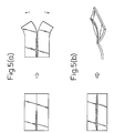
- the deformation in a plane is defined as a welding deformation existing in the same plane. A typical deformation in a plane is shown in Fig. 5(a).
- the welding deformation shown in Fig. 5(a) is formed when a groove ahead of the welding bead is opened during the process of welding.
- This welding deformation is formed as if the steel plates to be welded were rotated around the welding arc. Therefore, this welding deformation is referred to as a rotational deformation.
- end cracks are caused by this rotational deformation.
- the deformation out of a plane is a welding deformation which is not disposed in the same plane.
- a typical example of the deformation out of a plane is shown in Fig. 5(b). This deformation out of a plane is caused when an amount of deformation of the surface and that of the back surface are different. In the case shown in Fig. 5(b), a corner deformation and deflection are caused on the steel plates to be welded.
- the heat input for each electrode is increased, so that an amount of deposited metal for each electrode is also increased.
- a difference between the width of a welding bead of the surface and that of the back surface tends to increase, and also the reinforcement of the weld tends to increase.
- the reason why the currents of the first and second electrodes are set at a value not less than 900 A is that the minimum current 900 A is required for forming a key hole using an arc force.
- the reason why the upper limit 2400 A is determined is that when the current is increased to be higher than 2400 A, a melting pool goes out of control so that an excellent bead cannot be formed.
- Concerning the third electrode and after that, these succeeding electrodes function so as to form a surface bead.
- the reason why the upper limit of welding speed is set at 3,33 cm/s (200 cm/min) is that the occurrence of welding defects such as undercut is prevented when the welding speed is lower than the limit.
- the occurrence of welding deformation is determined by the welding condition, and selection of flux is not related to welding deformation.
- the lower limit of the currents of the first and second electrodes is 900 A, and the upper limit is 2400 A.
- flux of high fire resistance is required.
- the bonded type flux is provided with high fire resistance. Therefore, flux is limited to the bonded type flux in the present invention.
- Fig. 7 shows Y, V, I and U grooves to which the groove of the present invention is restricted for providing an excellent welding bead in one side welding for joining plates.
- the U groove is not limited to the example shown in the drawing, and an modified U groove is included.
- the groove configuration is limited to reduce welding deformation and provide a bead having an excellent configuration.
- a steel plate of which the tensile strength is lower than 390 MPa is not suitable for a welded construction, so that the lower limit of the tensile strength is set at a value not less than 390 MPa.
- the reason why the upper limit of the tensile strength is set at 780 MPa is that in the case of a steel plate of which the tensile strength is not less than 780 MPa, there is a possibility that the toughness of a welded portion is deteriorated in one side welding for joining steel plates. For this reason, the upper limit is set at this value for securing the reliability of the welded portion.
- the wall thickness from the viewpoint of practical use, only steel plates of which the wall thickness is not less than 8 mm are subjected to one side welding for joining. This is the reason why the lower limit is set at 8 mm.
- the reason why the upper limit of the wall thickness is set at 50 mm is described that when steel plates of which the wall thickness is not less than 50 mm are subjected to one side welding for joining, the current of each electrode is excessively increased, and there is a possibility that a welding bead of excellent configuration cannot be provided.
- the wall thickness becomes large, the amount of deposited metal is increased, so that the welding speed is lowered and the welding operation cannot be executed effectively. Further, when an excessive amount of heat input is applied to the steel plate to be welded, the toughness of the steel plate is deteriorated.
- the parameter P can be lowered, that is, an amount of welding deformation is reduced, and a welded joint having an excellent bead configuration can be provided at a relatively high welding efficiency in which the welding speed is maintained in the range of 1 to 3.33 cm/s (60 to 200 cm/min).
- welding electrodes 2a, 2b, 2c, 2d were respectively connected to welding power sources 11a, 11b, lic, 11d.
- These welding power sources 11a to lid were connected with a welding condition control unit 12 and parameter computing unit 13.
- the following were used so as to compute the parameter P from the expression (2): the maximum height H of a tack-welded bead which was previously measured; the heat input Qi found by the expression (1) from the current, voltage and welding speed of the i-th electrode; the distance Li from the first to the i-th electrode; and the constant k.
- H was made to be half of the wall thickness of steel plates to be welded, and the welding conditions such as a current and voltage of each welding electrode, welding speed and a distance between electrodes were determined so that the value P could be not more than 0.14.
- the welding conditions such as a current and voltage in each welding electrode, welding speed and distance between the electrodes were determined using the parameter Ptab so that H and Ht could be not more than half of the wall thickness of the steel plates to be welded and so that the value P could be not more than 0.26 and the value Ptab could be not less than 0.009.
- the parameter Ptab was computed by the expression (3) using the maximum height H of the tack-welded bead at the butted portion of the steel plates 1, 1' to be welded, the thickness of the tab, and the maximum value Ht of the tack-welded bead formed between the tab and the steel plates to be welded.
- Tables 1 and 2 there are shown welding conditions adopted in the present invention such as a current I, voltage E, welding speed V and distance between electrodes L.
- Tables 1 and 2 there are also shown a wall thickness, maximum height H of a tack-welded bead formed in the butted groove, parameter P (shown in expression (2)) computed according to the welding condition, and groove configuration.
- Concerning constant k three values 10, 50, 150 were selected.
- the groove angle ⁇ and root face Rf of the groove configuration shown on Tables 1 and 2 respectively correspond to ⁇ and Rf shown in Fig. 1.
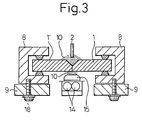
- the tab 4 was welded to the steel plates 1, 1' to be welded as illustrated in Figs. 2 and 3.
- pieces of cut wire were scattered between the tab 4 and the steel plates 1, 1' to be welded.
- the transversal shrinkage of residual deformation was measured in the following manner. Two contact balls 6 were respectively provided beforehand at a position separated from the end portion by 50 mm and also separated from the center of the groove by 50 mm. A distance between the contact balls 6 was measured before and after the welding operation, and its difference was found. This difference was used as the transversal shrinkage. An amount of angular deformation was found in such a manner that an angle of the steel plate was measured with an angle gauge, and a difference between before and after the welding operation was determined as the angular deformation. In Tables 3 and 4, results of the measurement of the amounts of these three types of deformation are shown in the cases of the conventional method and the comparative example.
- the amounts of deformation during welding were suppressed to a value not more than 1.00 mm in the same manner as the conventional method.
- the amounts of deformation during welding were respectively 3.25 mm and 2.55 mm, which are large, and even in the cases of Nos. 19 and 20 in which burner heating was conducted in Nos. 12 and 13, the amounts of deformation during welding were not reduced to a value not more than 1.00 mm.
- the amounts of deformation were reduced to a value not more than 1.00 mm only when the steel plates to be welded were restrained by a tab in the same manner as the conventional methods of Nos. 38 and 39.
- the amounts of deformation during welding were suppressed to a value not more than 1.00 mm, however, the amounts of transversal shrinkage were 0.63 mm, 0.75 mm and 0.65 mm which were larger than 0.60 mm.
- all the amounts of transversal shrinkage were not more than 0.60 mm in the same manner as the conventional method, and the amounts of transversal shrinkage were reduced to a value relatively smaller than those of the cases Nos. 37, 38 and 39 which were the conventional method in which a restraining force to restrain the steel plates was high.
- an amount of welding deformation can be reduced in the same manner as the conventional method.
Landscapes
- Engineering & Computer Science (AREA)
- Physics & Mathematics (AREA)
- Plasma & Fusion (AREA)
- Mechanical Engineering (AREA)
- Theoretical Computer Science (AREA)
- Arc Welding In General (AREA)
- Butt Welding And Welding Of Specific Article (AREA)
Applications Claiming Priority (4)
| Application Number | Priority Date | Filing Date | Title |
|---|---|---|---|
| JP1772493 | 1993-02-04 | ||
| JP17724/93 | 1993-02-04 | ||
| JP1772493 | 1993-02-04 | ||
| PCT/JP1994/000162 WO1994017951A1 (en) | 1993-02-04 | 1994-02-03 | Welding deformation reducing method for one-side strap joint welding |
Publications (3)
| Publication Number | Publication Date |
|---|---|
| EP0647495A1 EP0647495A1 (en) | 1995-04-12 |
| EP0647495A4 EP0647495A4 (en) | 1995-07-26 |
| EP0647495B1 true EP0647495B1 (en) | 2002-05-29 |
Family
ID=11951700
Family Applications (1)
| Application Number | Title | Priority Date | Filing Date |
|---|---|---|---|
| EP94905844A Expired - Lifetime EP0647495B1 (en) | 1993-02-04 | 1994-02-03 | Welding deformation reducing method for one-side strap joint welding |
Country Status (11)
| Country | Link |
|---|---|
| US (1) | US5550347A (zh) |
| EP (1) | EP0647495B1 (zh) |
| KR (2) | KR0143946B1 (zh) |
| CN (1) | CN1043018C (zh) |
| DE (1) | DE69430690T2 (zh) |
| FI (1) | FI944603A (zh) |
| PL (1) | PL173981B1 (zh) |
| RU (1) | RU2104847C1 (zh) |
| SG (1) | SG47924A1 (zh) |
| TW (1) | TW262422B (zh) |
| WO (1) | WO1994017951A1 (zh) |
Families Citing this family (28)
| Publication number | Priority date | Publication date | Assignee | Title |
|---|---|---|---|---|
| US5729345A (en) * | 1996-09-11 | 1998-03-17 | Caterpillar Inc. | Apparatus and method for determining distortion of a welded member |
| RU2158668C2 (ru) * | 1999-02-04 | 2000-11-10 | Открытое акционерное общество НПО Энергомаш им. акад. В.П. Глушко | Способ получения сварного соединения |
| US6175093B1 (en) * | 1999-08-18 | 2001-01-16 | Abb Alstpm Power Inc. | Method for applying a weld overlay to a wastage susceptible structure |
| US6770834B1 (en) * | 2000-03-02 | 2004-08-03 | Kent Deshotel | Welding machine |
| US7006958B2 (en) * | 2000-07-21 | 2006-02-28 | Caterpillar Inc. | Method for controlling distortion of a material during a weld process |
| JP4734513B2 (ja) * | 2005-05-31 | 2011-07-27 | 株式会社Ihi | 突合わせ溶接変形実験試験片 |
| JP5426076B2 (ja) * | 2007-02-19 | 2014-02-26 | 株式会社ダイヘン | アーク溶接のビード形状シミュレーション装置 |
| WO2010098700A1 (en) * | 2009-02-24 | 2010-09-02 | Esab Ab | Arc welding method and apparatus for arc welding |
| CN101905385A (zh) * | 2010-08-04 | 2010-12-08 | 江苏申港锅炉有限公司 | 不锈钢管的对接坡口结构 |
| CN102059429A (zh) * | 2010-12-14 | 2011-05-18 | 广州中船黄埔造船有限公司 | 槽形壁与轻围壁的平台对接方法 |
| CN102398120A (zh) * | 2011-02-22 | 2012-04-04 | 汪砚秋 | 钢构件防变形焊接工艺 |
| CN102430868A (zh) * | 2011-10-25 | 2012-05-02 | 王建军 | 四氟板隐缝焊接的方法 |
| WO2014097419A1 (ja) * | 2012-12-19 | 2014-06-26 | 三菱重工業株式会社 | 接合材の製造方法、及び接合用治具 |
| CN103817416A (zh) * | 2014-01-27 | 2014-05-28 | 天津新港船舶重工有限责任公司 | 钢质薄板对接的一次成型埋弧焊接方法 |
| CN104148863B (zh) * | 2014-08-25 | 2016-05-25 | 湖南晟通天力汽车有限公司 | 防焊接变形夹具 |
| CN104476142B (zh) * | 2014-12-19 | 2017-06-16 | 青岛维尔环保科技有限公司 | 滑道梁防变形制作工艺 |
| CN105149801B (zh) * | 2015-09-22 | 2017-05-24 | 中车唐山机车车辆有限公司 | 焊接件收缩变形量的拉伸装置 |
| CN108698154A (zh) * | 2016-02-19 | 2018-10-23 | 杰富意钢铁株式会社 | 多电极埋弧焊方法 |
| CN105798471B (zh) * | 2016-05-31 | 2017-11-14 | 哈尔滨工业大学 | 一种抑制t型结构件焊接热裂纹的装置及方法 |
| CN105921895B (zh) * | 2016-05-31 | 2018-03-13 | 哈尔滨工业大学 | 一种减小t型结构件焊接挠曲变形的预拉伸装置及方法 |
| CN105857413A (zh) * | 2016-06-23 | 2016-08-17 | 北京新能源汽车股份有限公司 | 车身连接结构和具有其的车辆 |
| CN106225968B (zh) * | 2016-07-28 | 2019-02-19 | 中国神华能源股份有限公司 | 焊接拘束应力测试方法和焊接拘束应力测试装置制造方法 |
| JP6777609B2 (ja) * | 2017-09-11 | 2020-10-28 | 株式会社神戸製鋼所 | 多電極ガスシールドアーク溶接方法 |
| CN109014632A (zh) * | 2018-09-29 | 2018-12-18 | 北京首钢建设集团有限公司 | 一种利用矩形钢板块控制焊接变形的方法 |
| CN110253111A (zh) * | 2019-07-12 | 2019-09-20 | 中船桂江造船有限公司 | 一种1cr18ni钢板+铝铝钢复合材料焊接方法 |
| CN110508911B (zh) * | 2019-09-06 | 2021-07-09 | 上海外高桥造船有限公司 | Y型拼板缝焊接方法 |
| CN113510350B (zh) * | 2021-04-27 | 2022-12-02 | 广船国际有限公司 | 一种薄板埋弧焊接参数评定方法 |
| CN115365691B (zh) * | 2022-08-16 | 2023-09-15 | 北京首钢建设集团有限公司 | 一种钢结构滑雪跳台赛道面板成形精度控制方法 |
Family Cites Families (8)
| Publication number | Priority date | Publication date | Assignee | Title |
|---|---|---|---|---|
| US1512787A (en) * | 1924-02-05 | 1924-10-21 | Harry D Morton | Means and method for effecting continuous electric-arc welds |
| US2106987A (en) * | 1936-12-22 | 1938-02-01 | Laurence C Powell | Distortion check for welding apparatus |
| US2449082A (en) * | 1946-04-05 | 1948-09-14 | Louis P Mccabe | Method of preventing distortion in butt-welded plates |
| US4046988A (en) * | 1976-03-05 | 1977-09-06 | Kobe Steel Ltd. | Method of preventing base metal end crack in arc welding and end tab used therefor |
| JPS5351153A (en) * | 1976-10-22 | 1978-05-10 | Hitachi Ltd | Oneeside welding |
| JPS6422469A (en) * | 1987-07-20 | 1989-01-25 | Nippon Kokan Kk | Automatic arc welding method |
| JPH04143075A (ja) * | 1990-10-05 | 1992-05-18 | Nippon Steel Corp | 多電極片面サブマージドアーク溶接条件推定方法 |
| US5214265A (en) * | 1990-11-15 | 1993-05-25 | Pollack Alex J | High speed low deposition submerged arc welding apparatus and method |
-
1994
- 1994-02-03 DE DE69430690T patent/DE69430690T2/de not_active Expired - Lifetime
- 1994-02-03 CN CN94190089A patent/CN1043018C/zh not_active Expired - Lifetime
- 1994-02-03 SG SG1996005397A patent/SG47924A1/en unknown
- 1994-02-03 PL PL94305548A patent/PL173981B1/pl unknown
- 1994-02-03 WO PCT/JP1994/000162 patent/WO1994017951A1/ja active IP Right Grant
- 1994-02-03 RU RU94045974A patent/RU2104847C1/ru active
- 1994-02-03 US US08/313,271 patent/US5550347A/en not_active Expired - Fee Related
- 1994-02-03 KR KR1019940703486A patent/KR0143946B1/ko active
- 1994-02-03 EP EP94905844A patent/EP0647495B1/en not_active Expired - Lifetime
- 1994-02-04 TW TW083100942A patent/TW262422B/zh not_active IP Right Cessation
- 1994-10-03 FI FI944603A patent/FI944603A/fi unknown
- 1994-10-04 KR KR1019940703486A patent/KR950700804A/ko not_active IP Right Cessation
Also Published As
| Publication number | Publication date |
|---|---|
| US5550347A (en) | 1996-08-27 |
| FI944603A (fi) | 1994-12-02 |
| DE69430690T2 (de) | 2002-09-12 |
| EP0647495A1 (en) | 1995-04-12 |
| RU94045974A (ru) | 1996-09-20 |
| FI944603A0 (fi) | 1994-10-03 |
| CN1102931A (zh) | 1995-05-24 |
| KR0143946B1 (ko) | 1998-08-17 |
| EP0647495A4 (en) | 1995-07-26 |
| RU2104847C1 (ru) | 1998-02-20 |
| CN1043018C (zh) | 1999-04-21 |
| TW262422B (zh) | 1995-11-11 |
| SG47924A1 (en) | 1998-04-17 |
| KR950700804A (ko) | 1995-02-20 |
| PL305548A1 (en) | 1995-01-23 |
| DE69430690D1 (de) | 2002-07-04 |
| WO1994017951A1 (en) | 1994-08-18 |
| PL173981B1 (pl) | 1998-05-29 |
Similar Documents
| Publication | Publication Date | Title |
|---|---|---|
| EP0647495B1 (en) | Welding deformation reducing method for one-side strap joint welding | |
| Berge | On the effect of plate thickness in fatigue of welds | |
| JP3168927B2 (ja) | 2相系ステンレス鋼の継手の製造方法 | |
| Dawes | Fracture control in high yield strength weldments | |
| JP4733955B2 (ja) | 耐脆性き裂伝播性に優れた溶接構造体の溶接方法 | |
| US20100001044A1 (en) | Full penetration weld joint | |
| Conrardy et al. | Control of distortion in thin ship panels | |
| US20020179583A1 (en) | Highly ductile reduced imperfection weld for ductile iron and method for producing same | |
| JP2700878B2 (ja) | 抵抗溶接機の溶接電流制御装置 | |
| Funderburk | Fundamentals of preheat | |
| JP2934315B2 (ja) | 片面板継ぎ溶接の溶接変形低減方法 | |
| JPS5937157B2 (ja) | ステンレスクラツド鋼継手の片面溶接方法 | |
| JP3362624B2 (ja) | 重ね溶接継手の疲労特性向上方法 | |
| Jennings | Welding design | |
| JP2878539B2 (ja) | チタンクラッド鋼の溶接方法 | |
| JP3339322B2 (ja) | チタンクラッド鋼板の溶接方法 | |
| Ohta et al. | FATIGUE STRENGTH OF BUTT WELDED Al–Mg ALUMINIUM ALLOY: TESTS WITH MAXIMUM STRESS AT YIELD STRENGTH | |
| JPS5820394A (ja) | 溶接方法 | |
| JPH0819860A (ja) | 構造用鋼回し溶接継手の溶接方法 | |
| JPS61150783A (ja) | 低温用鋼材の溶接方法 | |
| JPH0663756A (ja) | T形継手パネルの溶接歪防止法 | |
| JPH11267829A (ja) | ボックス構造継手の溶接施工方法 | |
| JP2000218370A (ja) | 構造用鋼の溶接継手部の疲労強度の向上方法 | |
| JPH02224873A (ja) | クラッド鋼の溶接部構造および溶接方法 | |
| McKenzie | British developments in the use of steel to BS 968: 1962 in welded construction |
Legal Events
| Date | Code | Title | Description |
|---|---|---|---|
| PUAI | Public reference made under article 153(3) epc to a published international application that has entered the european phase |
Free format text: ORIGINAL CODE: 0009012 |
|
| 17P | Request for examination filed |
Effective date: 19940928 |
|
| AK | Designated contracting states |
Kind code of ref document: A1 Designated state(s): DE DK ES FR GB IT |
|
| A4 | Supplementary search report drawn up and despatched | ||
| AK | Designated contracting states |
Kind code of ref document: A4 Designated state(s): DE DK ES FR GB IT |
|
| 17Q | First examination report despatched |
Effective date: 19990602 |
|
| GRAG | Despatch of communication of intention to grant |
Free format text: ORIGINAL CODE: EPIDOS AGRA |
|
| GRAG | Despatch of communication of intention to grant |
Free format text: ORIGINAL CODE: EPIDOS AGRA |
|
| GRAH | Despatch of communication of intention to grant a patent |
Free format text: ORIGINAL CODE: EPIDOS IGRA |
|
| GRAH | Despatch of communication of intention to grant a patent |
Free format text: ORIGINAL CODE: EPIDOS IGRA |
|
| GRAA | (expected) grant |
Free format text: ORIGINAL CODE: 0009210 |
|
| AK | Designated contracting states |
Kind code of ref document: B1 Designated state(s): DE DK ES FR GB IT |
|
| PG25 | Lapsed in a contracting state [announced via postgrant information from national office to epo] |
Ref country code: IT Free format text: LAPSE BECAUSE OF FAILURE TO SUBMIT A TRANSLATION OF THE DESCRIPTION OR TO PAY THE FEE WITHIN THE PRE;WARNING: LAPSES OF ITALIAN PATENTS WITH EFFECTIVE DATE BEFORE 2007 MAY HAVE OCCURRED AT ANY TIME BEFORE 2007. THE CORRECT EFFECTIVE DATE MAY BE DIFFERENT FROM THE ONE RECORDED.SCRIBED TIME-LIMIT Effective date: 20020529 Ref country code: FR Free format text: LAPSE BECAUSE OF FAILURE TO SUBMIT A TRANSLATION OF THE DESCRIPTION OR TO PAY THE FEE WITHIN THE PRESCRIBED TIME-LIMIT Effective date: 20020529 |
|
| REG | Reference to a national code |
Ref country code: GB Ref legal event code: FG4D |
|
| REF | Corresponds to: |
Ref document number: 69430690 Country of ref document: DE Date of ref document: 20020704 |
|
| PG25 | Lapsed in a contracting state [announced via postgrant information from national office to epo] |
Ref country code: DK Free format text: LAPSE BECAUSE OF FAILURE TO SUBMIT A TRANSLATION OF THE DESCRIPTION OR TO PAY THE FEE WITHIN THE PRESCRIBED TIME-LIMIT Effective date: 20020829 |
|
| PG25 | Lapsed in a contracting state [announced via postgrant information from national office to epo] |
Ref country code: ES Free format text: LAPSE BECAUSE OF FAILURE TO SUBMIT A TRANSLATION OF THE DESCRIPTION OR TO PAY THE FEE WITHIN THE PRESCRIBED TIME-LIMIT Effective date: 20021128 |
|
| EN | Fr: translation not filed | ||
| PG25 | Lapsed in a contracting state [announced via postgrant information from national office to epo] |
Ref country code: GB Free format text: LAPSE BECAUSE OF NON-PAYMENT OF DUE FEES Effective date: 20030203 |
|
| PLBE | No opposition filed within time limit |
Free format text: ORIGINAL CODE: 0009261 |
|
| STAA | Information on the status of an ep patent application or granted ep patent |
Free format text: STATUS: NO OPPOSITION FILED WITHIN TIME LIMIT |
|
| 26N | No opposition filed |
Effective date: 20030303 |
|
| GBPC | Gb: european patent ceased through non-payment of renewal fee | ||
| PGFP | Annual fee paid to national office [announced via postgrant information from national office to epo] |
Ref country code: DE Payment date: 20130327 Year of fee payment: 20 |
|
| REG | Reference to a national code |
Ref country code: DE Ref legal event code: R071 Ref document number: 69430690 Country of ref document: DE |
|
| REG | Reference to a national code |
Ref country code: DE Ref legal event code: R071 Ref document number: 69430690 Country of ref document: DE |
|
| PG25 | Lapsed in a contracting state [announced via postgrant information from national office to epo] |
Ref country code: DE Free format text: LAPSE BECAUSE OF EXPIRATION OF PROTECTION Effective date: 20140204 |