EP0647495A1 - Procede d'attenuation de la deformation au soudage pour soudage par points a couvre-joint - Google Patents
Procede d'attenuation de la deformation au soudage pour soudage par points a couvre-joint Download PDFInfo
- Publication number
- EP0647495A1 EP0647495A1 EP94905844A EP94905844A EP0647495A1 EP 0647495 A1 EP0647495 A1 EP 0647495A1 EP 94905844 A EP94905844 A EP 94905844A EP 94905844 A EP94905844 A EP 94905844A EP 0647495 A1 EP0647495 A1 EP 0647495A1
- Authority
- EP
- European Patent Office
- Prior art keywords
- welding
- welded
- electrode
- distortion
- tack
- Prior art date
- Legal status (The legal status is an assumption and is not a legal conclusion. Google has not performed a legal analysis and makes no representation as to the accuracy of the status listed.)
- Granted
Links
Images


Classifications
-
- B—PERFORMING OPERATIONS; TRANSPORTING
- B23—MACHINE TOOLS; METAL-WORKING NOT OTHERWISE PROVIDED FOR
- B23K—SOLDERING OR UNSOLDERING; WELDING; CLADDING OR PLATING BY SOLDERING OR WELDING; CUTTING BY APPLYING HEAT LOCALLY, e.g. FLAME CUTTING; WORKING BY LASER BEAM
- B23K9/00—Arc welding or cutting
- B23K9/095—Monitoring or automatic control of welding parameters
- B23K9/0953—Monitoring or automatic control of welding parameters using computing means
Definitions
- the present invention is intended to provide a method of reducing welding distortion in one side welding for joining plates, wherein the method is based on the welding condition described above.
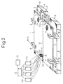
- Fig. 3 is a sectional schematic illustration taken on line A - A in Fig. 2
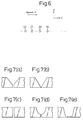
- Figs. 7(a) to 7(e) show types of the groove configuration, wherein Fig. (a) is a view showing a Y-groove, Fig. (b) is a view showing a V-groove, Fig. (c) is a view showing an I-groove, Fig. (d) is a view showing a U-groove, and Fig. (e) is a view showing another groove.
- the present invention is intended to provide a method of reducing welding distortion in one side welding for joining plates in which steel plates to be welded are butted against each other, a tack-welded bead is formed and fixed in a groove, and not less than three electrodes are applied, the method of reducing welding distortion in one side welding for joining plates comprising the steps of: estimating a distortion stress generated in the process of welding using an amount of heat input Qi (kJ/mm) computed by the following expression (1) and also using a parameter P computed by the following expression (2); and determining a welding condition of each electrode so that the distortion stress can be in an allowable range.
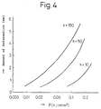
- Fig. 4 shows that the parameter P corresponds to an amount of deformation.
- the horizontal axis in Fig. 4 expresses an amount of deformation caused during the welding operation in an example described later. Therefore, it can be understood that the parameter P is in a good correlation with the amount of deformation caused during the welding operation. Due to the foregoing, when the value P is suppressed in a predetermined range, an amount of deformation can be reduced.
- the parameter Ptab used for the tab has the same relation as that of the tack-welded bead described above.
- the tab restrains the steel plates to be welded in the same manner as the tack-welded bead. Therefore, it is possible to evaluate the function of the tab in the same manner.
- H is the maximum of the height of the tack-welded bead provided in a butted groove.
- a parameter to find a relation between the welding deformation behavior and the welding condition can be described by Qi and Li.
- the steel plates to be welded are not subjected to tack welding at all, that is, when a tack-welded bead is not formed in the groove at all and the steel plates to be welded are not restrained by a tab, the steel plates to be welded are not restrained at all. In this case, even when a welding condition to reduce an amount of welding deformation is adopted, it is substantially impossible to conduct welding. Consequently, it is essentially necessary to restrain the steel plates by a minimum amount of tack-welded bead. Therefore, it is necessary to find a parameter expressing this influence.
- the values of H and Ht are higher than half of the wall thickness of the steel plates to be welded, it is contrary to the object of the present invention. Therefore, the values H and Ht are set to be not more than half of the wall thickness of the steel plate to be welded.
- the steel plates to be welded are mainly restrained by the tack-welded bead formed in the butted groove.
- the value P becomes higher than 0.14. Therefore, it is impossible to realize a reduction in welding deformation unless a tab is used for restraining the steel plates or gas burners are used for controlling the thermal history.
- the welding deformation shown in Fig. 5(a) is formed when a groove ahead of the welding bead is opened during the process of welding.
- This welding deformation is formed as if the steel plates to be welded were rotated around the welding arc. Therefore, this welding deformation is referred to as a rotational deformation.
- end cracks are caused by this rotational deformation.
- succeeding electrodes are different from the preceding electrodes, and it is not necessary to form a back bead (uranami) with these succeeding electrodes, and it is also not necessary to form a key hole with these succeeding electrodes. For this reason, it is possible to form an excellent bead using a current lower than that of the first and second electrodes.
- the reason why the upper limit of the third electrode and after that is set at 2400 A is the same as that of the first and second electrodes. High welding speed is advantageous for enhancing the labor efficiency. However, when the welding speed is too high, welding defects such as undercut are caused. The reason why the upper limit of welding speed is set at 200 cm/min is that the occurrence of welding defects such as undercut is prevented when the welding speed is lower than the limit.
- the occurrence of welding deformation is determined by the welding condition, and selection of flux is not related to welding deformation.
- the lower limit of the currents of the first and second electrodes is 900 A, and the upper limit is 2400 A.
- flux of high fire resistance is required.
- the bonded type flux is provided with high fire resistance. Therefore, flux is limited to the bonded type flux in the present invention.
- a steel plate of which the tensile strength is lower than 390 MPa is not suitable for a welded construction, so that the lower limit of the tensile strength is set at a value not less than 390 MPa.
- the reason why the upper limit of the tensile strength is set at 780 MPa is that in the case of a steel plate of which the tensile strength is not less than 780 MPa, there is a possibility that the toughness of a welded portion is deteriorated in one side welding for joining steel plates. For this reason, the upper limit is set at this value for securing the reliability of the welded portion.
- the parameter P can be lowered, that is, an amount of welding deformation is reduced, and a welded joint having an excellent bead configuration can be provided at a relatively high welding efficiency in which the welding speed is maintained in the range of 60 to 200 cm/min.
- H was made to be half of the wall thickness of steel plates to be welded, and the welding conditions such as a current and voltage of each welding electrode, welding speed and a distance between electrodes were determined so that the value P could be not more than 0.14.
- the welding conditions such as a current and voltage in each welding electrode, welding speed and distance between the electrodes were determined using the parameter Ptab so that H and Ht could be not more than half of the wall thickness of the steel plates to be welded and so that the value P could be not more than 0.26 and the value Ptab could be not less than 0.009.
- the parameter Ptab was computed by the expression (3) using the maximum height H of the tack-welded bead at the butted portion of the steel plates 1, 1' to be welded, the thickness of the tab, and the maximum value Ht of the tack-welded bead formed between the tab and the steel plates to be welded.
- Tables 1 and 2 there are shown welding conditions adopted in the present invention such as a current I, voltage E, welding speed V and distance between electrodes L.
- Tables 1 and 2 there are also shown a wall thickness, maximum height H of a tack-welded bead formed in the butted groove, parameter P (shown in expression (2)) computed according to the welding condition, and groove configuration.
- Concerning constant k three values 10, 50, 150 were selected.
- the groove angle ⁇ and root face Rf of the groove configuration shown on Tables 1 and 2 respectively correspond to ⁇ and Rf shown in Fig. 1.
- the tab 4 was welded to the steel plates 1, 1' to be welded as illustrated in Figs. 2 and 3.
- pieces of cut wire were scattered between the tab 4 and the steel plates 1, 1' to be welded.
- the amounts of deformation during welding were suppressed to a value not more than 1.00 mm in the same manner as the conventional method.
- the amounts of deformation during welding were respectively 3.25 mm and 2.55 mm, which are large, and even in the cases of Nos. 19 and 20 in which burner heating was conducted in Nos. 12 and 13, the amounts of deformation during welding were not reduced to a value not more than 1.00 mm.
- the amounts of deformation were reduced to a value not more than 1.00 mm only when the steel plates to be welded were restrained by a tab in the same manner as the conventional methods of Nos. 38 and 39.
- the amounts of deformation during welding were suppressed to a value not more than 1.00 mm, however, the amounts of transversal shrinkage were 0.63 mm, 0.75 mm and 0.65 mm which were larger than 0.60 mm.
- all the amounts of transversal shrinkage were not more than 0.60 mm in the same manner as the conventional method, and the amounts of transversal shrinkage were reduced to a value relatively smaller than those of the cases Nos. 37, 38 and 39 which were the conventional method in which a restraining force to restrain the steel plates was high.
Landscapes
- Engineering & Computer Science (AREA)
- Physics & Mathematics (AREA)
- Plasma & Fusion (AREA)
- Mechanical Engineering (AREA)
- Theoretical Computer Science (AREA)
- Arc Welding In General (AREA)
- Butt Welding And Welding Of Specific Article (AREA)
Applications Claiming Priority (4)
| Application Number | Priority Date | Filing Date | Title |
|---|---|---|---|
| JP17724/93 | 1993-02-04 | ||
| JP1772493 | 1993-02-04 | ||
| JP1772493 | 1993-02-04 | ||
| PCT/JP1994/000162 WO1994017951A1 (fr) | 1993-02-04 | 1994-02-03 | Procede d'attenuation de la deformation au soudage pour soudage par points a couvre-joint |
Publications (3)
| Publication Number | Publication Date |
|---|---|
| EP0647495A1 true EP0647495A1 (fr) | 1995-04-12 |
| EP0647495A4 EP0647495A4 (fr) | 1995-07-26 |
| EP0647495B1 EP0647495B1 (fr) | 2002-05-29 |
Family
ID=11951700
Family Applications (1)
| Application Number | Title | Priority Date | Filing Date |
|---|---|---|---|
| EP94905844A Expired - Lifetime EP0647495B1 (fr) | 1993-02-04 | 1994-02-03 | Procede d'attenuation de la deformation au soudage pour soudage par points a couvre-joint |
Country Status (11)
| Country | Link |
|---|---|
| US (1) | US5550347A (fr) |
| EP (1) | EP0647495B1 (fr) |
| KR (2) | KR0143946B1 (fr) |
| CN (1) | CN1043018C (fr) |
| DE (1) | DE69430690T2 (fr) |
| FI (1) | FI944603A7 (fr) |
| PL (1) | PL173981B1 (fr) |
| RU (1) | RU2104847C1 (fr) |
| SG (1) | SG47924A1 (fr) |
| TW (1) | TW262422B (fr) |
| WO (1) | WO1994017951A1 (fr) |
Cited By (5)
| Publication number | Priority date | Publication date | Assignee | Title |
|---|---|---|---|---|
| WO2002007921A1 (fr) * | 2000-07-21 | 2002-01-31 | Caterpillar, Inc. | Procede permettant de reguler des distorsions de materiau pendant un processus de soudage |
| CN105857413A (zh) * | 2016-06-23 | 2016-08-17 | 北京新能源汽车股份有限公司 | 车身连接结构和具有其的车辆 |
| CN106225968A (zh) * | 2016-07-28 | 2016-12-14 | 中国神华能源股份有限公司 | 焊接拘束应力测试方法和焊接拘束应力测试装置制造方法 |
| CN110253111A (zh) * | 2019-07-12 | 2019-09-20 | 中船桂江造船有限公司 | 一种1cr18ni钢板+铝铝钢复合材料焊接方法 |
| RU2702168C1 (ru) * | 2017-09-11 | 2019-10-04 | Кабусики Кайся Кобе Сейко Се (Кобе Стил, Лтд.) | Способ многоэлектродной дуговой сварки в среде защитного газа |
Families Citing this family (29)
| Publication number | Priority date | Publication date | Assignee | Title |
|---|---|---|---|---|
| US5729345A (en) * | 1996-09-11 | 1998-03-17 | Caterpillar Inc. | Apparatus and method for determining distortion of a welded member |
| RU2158668C2 (ru) * | 1999-02-04 | 2000-11-10 | Открытое акционерное общество НПО Энергомаш им. акад. В.П. Глушко | Способ получения сварного соединения |
| US6175093B1 (en) * | 1999-08-18 | 2001-01-16 | Abb Alstpm Power Inc. | Method for applying a weld overlay to a wastage susceptible structure |
| US6770834B1 (en) * | 2000-03-02 | 2004-08-03 | Kent Deshotel | Welding machine |
| RU2278008C2 (ru) * | 2003-06-11 | 2006-06-20 | ОАО "НПО "Энергомаш имени академика В.П. Глушко" | Способ сварки толстостенных крупногабаритных деталей |
| AT501489B1 (de) * | 2005-02-25 | 2009-07-15 | Fronius Int Gmbh | Verfahren zum steuern und/oder regeln eines schweissgerätes und schweissgerät |
| JP4734513B2 (ja) * | 2005-05-31 | 2011-07-27 | 株式会社Ihi | 突合わせ溶接変形実験試験片 |
| JP5426076B2 (ja) * | 2007-02-19 | 2014-02-26 | 株式会社ダイヘン | アーク溶接のビード形状シミュレーション装置 |
| JP5497072B2 (ja) * | 2009-02-24 | 2014-05-21 | イーエスエービー・エービー | アーク溶接方法およびアーク溶接のための装置 |
| CN101905385A (zh) * | 2010-08-04 | 2010-12-08 | 江苏申港锅炉有限公司 | 不锈钢管的对接坡口结构 |
| CN102059429A (zh) * | 2010-12-14 | 2011-05-18 | 广州中船黄埔造船有限公司 | 槽形壁与轻围壁的平台对接方法 |
| CN102398120A (zh) * | 2011-02-22 | 2012-04-04 | 汪砚秋 | 钢构件防变形焊接工艺 |
| CN102430868A (zh) * | 2011-10-25 | 2012-05-02 | 王建军 | 四氟板隐缝焊接的方法 |
| JP5863996B2 (ja) * | 2012-12-19 | 2016-02-17 | 三菱重工業株式会社 | 接合材の製造方法、及び接合用治具 |
| CN103817416A (zh) * | 2014-01-27 | 2014-05-28 | 天津新港船舶重工有限责任公司 | 钢质薄板对接的一次成型埋弧焊接方法 |
| CN104148863B (zh) * | 2014-08-25 | 2016-05-25 | 湖南晟通天力汽车有限公司 | 防焊接变形夹具 |
| CN104476142B (zh) * | 2014-12-19 | 2017-06-16 | 青岛维尔环保科技有限公司 | 滑道梁防变形制作工艺 |
| CN105149801B (zh) * | 2015-09-22 | 2017-05-24 | 中车唐山机车车辆有限公司 | 焊接件收缩变形量的拉伸装置 |
| JP6605596B2 (ja) * | 2016-02-19 | 2019-11-13 | Jfeスチール株式会社 | 多電極サブマージアーク溶接方法 |
| CN105921895B (zh) * | 2016-05-31 | 2018-03-13 | 哈尔滨工业大学 | 一种减小t型结构件焊接挠曲变形的预拉伸装置及方法 |
| CN105798471B (zh) * | 2016-05-31 | 2017-11-14 | 哈尔滨工业大学 | 一种抑制t型结构件焊接热裂纹的装置及方法 |
| CN109014632A (zh) * | 2018-09-29 | 2018-12-18 | 北京首钢建设集团有限公司 | 一种利用矩形钢板块控制焊接变形的方法 |
| CN110508911B (zh) * | 2019-09-06 | 2021-07-09 | 上海外高桥造船有限公司 | Y型拼板缝焊接方法 |
| CN113510350B (zh) * | 2021-04-27 | 2022-12-02 | 广船国际有限公司 | 一种薄板埋弧焊接参数评定方法 |
| CN115365691B (zh) * | 2022-08-16 | 2023-09-15 | 北京首钢建设集团有限公司 | 一种钢结构滑雪跳台赛道面板成形精度控制方法 |
| CN116551129B (zh) * | 2023-03-16 | 2025-07-22 | 江苏扬子鑫福造船有限公司 | 船用超厚板拼板埋弧焊焊接工艺 |
| WO2024204428A1 (fr) * | 2023-03-31 | 2024-10-03 | Jfeスチール株式会社 | Procédé de fabrication d'un joint soudé par soudage à l'arc sous protection gazeuse d'une plaque d'acier |
| WO2024204429A1 (fr) * | 2023-03-31 | 2024-10-03 | Jfeスチール株式会社 | Procédé de production pour joint soudé par soudage à l'arc sous protection gazeuse d'une plaque d'acier |
| CN119952323B (zh) * | 2025-03-11 | 2025-09-30 | 武汉钢铁有限公司 | 开卷剪切板的焊接变形面异性的测量方法 |
Family Cites Families (8)
| Publication number | Priority date | Publication date | Assignee | Title |
|---|---|---|---|---|
| US1512787A (en) * | 1924-02-05 | 1924-10-21 | Harry D Morton | Means and method for effecting continuous electric-arc welds |
| US2106987A (en) * | 1936-12-22 | 1938-02-01 | Laurence C Powell | Distortion check for welding apparatus |
| US2449082A (en) * | 1946-04-05 | 1948-09-14 | Louis P Mccabe | Method of preventing distortion in butt-welded plates |
| US4046988A (en) * | 1976-03-05 | 1977-09-06 | Kobe Steel Ltd. | Method of preventing base metal end crack in arc welding and end tab used therefor |
| JPS5351153A (en) * | 1976-10-22 | 1978-05-10 | Hitachi Ltd | Oneeside welding |
| JPS6422469A (en) * | 1987-07-20 | 1989-01-25 | Nippon Kokan Kk | Automatic arc welding method |
| JPH04143075A (ja) * | 1990-10-05 | 1992-05-18 | Nippon Steel Corp | 多電極片面サブマージドアーク溶接条件推定方法 |
| US5214265A (en) * | 1990-11-15 | 1993-05-25 | Pollack Alex J | High speed low deposition submerged arc welding apparatus and method |
-
1994
- 1994-02-03 US US08/313,271 patent/US5550347A/en not_active Expired - Fee Related
- 1994-02-03 SG SG1996005397A patent/SG47924A1/en unknown
- 1994-02-03 RU RU94045974A patent/RU2104847C1/ru active
- 1994-02-03 EP EP94905844A patent/EP0647495B1/fr not_active Expired - Lifetime
- 1994-02-03 WO PCT/JP1994/000162 patent/WO1994017951A1/fr not_active Ceased
- 1994-02-03 PL PL94305548A patent/PL173981B1/pl unknown
- 1994-02-03 CN CN94190089A patent/CN1043018C/zh not_active Expired - Lifetime
- 1994-02-03 KR KR1019940703486A patent/KR0143946B1/ko not_active Expired - Lifetime
- 1994-02-03 DE DE69430690T patent/DE69430690T2/de not_active Expired - Lifetime
- 1994-02-04 TW TW083100942A patent/TW262422B/zh not_active IP Right Cessation
- 1994-10-03 FI FI944603A patent/FI944603A7/fi unknown
- 1994-10-04 KR KR1019940703486A patent/KR950700804A/ko active Granted
Cited By (7)
| Publication number | Priority date | Publication date | Assignee | Title |
|---|---|---|---|---|
| WO2002007921A1 (fr) * | 2000-07-21 | 2002-01-31 | Caterpillar, Inc. | Procede permettant de reguler des distorsions de materiau pendant un processus de soudage |
| US7006958B2 (en) | 2000-07-21 | 2006-02-28 | Caterpillar Inc. | Method for controlling distortion of a material during a weld process |
| CN105857413A (zh) * | 2016-06-23 | 2016-08-17 | 北京新能源汽车股份有限公司 | 车身连接结构和具有其的车辆 |
| CN106225968A (zh) * | 2016-07-28 | 2016-12-14 | 中国神华能源股份有限公司 | 焊接拘束应力测试方法和焊接拘束应力测试装置制造方法 |
| CN106225968B (zh) * | 2016-07-28 | 2019-02-19 | 中国神华能源股份有限公司 | 焊接拘束应力测试方法和焊接拘束应力测试装置制造方法 |
| RU2702168C1 (ru) * | 2017-09-11 | 2019-10-04 | Кабусики Кайся Кобе Сейко Се (Кобе Стил, Лтд.) | Способ многоэлектродной дуговой сварки в среде защитного газа |
| CN110253111A (zh) * | 2019-07-12 | 2019-09-20 | 中船桂江造船有限公司 | 一种1cr18ni钢板+铝铝钢复合材料焊接方法 |
Also Published As
| Publication number | Publication date |
|---|---|
| TW262422B (fr) | 1995-11-11 |
| FI944603A0 (fi) | 1994-10-03 |
| SG47924A1 (en) | 1998-04-17 |
| CN1102931A (zh) | 1995-05-24 |
| EP0647495A4 (fr) | 1995-07-26 |
| KR0143946B1 (ko) | 1998-08-17 |
| FI944603A7 (fi) | 1994-12-02 |
| RU94045974A (ru) | 1996-09-20 |
| WO1994017951A1 (fr) | 1994-08-18 |
| CN1043018C (zh) | 1999-04-21 |
| US5550347A (en) | 1996-08-27 |
| DE69430690D1 (de) | 2002-07-04 |
| RU2104847C1 (ru) | 1998-02-20 |
| DE69430690T2 (de) | 2002-09-12 |
| EP0647495B1 (fr) | 2002-05-29 |
| PL173981B1 (pl) | 1998-05-29 |
| KR950700804A (ko) | 1995-02-20 |
| PL305548A1 (en) | 1995-01-23 |
Similar Documents
| Publication | Publication Date | Title |
|---|---|---|
| EP0647495A1 (fr) | Procede d'attenuation de la deformation au soudage pour soudage par points a couvre-joint | |
| US6386427B2 (en) | One-side welding method for steel structure | |
| US7748596B2 (en) | Welded structure having excellent resistance to brittle crack propagation and welding method therefor | |
| US10974341B2 (en) | Welding waveform for stainless steel applications | |
| Conrardy et al. | Control of distortion in thin ship panels | |
| JPH08155635A (ja) | 疲労特性に優れた構造用鋼回し溶接継手およびその溶接方法 | |
| JP3362624B2 (ja) | 重ね溶接継手の疲労特性向上方法 | |
| JPS5939230B2 (ja) | 厚肉鋼材の突合せ両面容接法 | |
| JP2000225469A (ja) | 極厚鋼板製平板の溶接方法 | |
| JP2934315B2 (ja) | 片面板継ぎ溶接の溶接変形低減方法 | |
| Akonyi et al. | Optimisation of process parameters for MAG welding of API X70m material to predict tensile strength using Taguchi method | |
| Jennings | Welding design | |
| JP2878539B2 (ja) | チタンクラッド鋼の溶接方法 | |
| Russell | Application of laser welding in shipyards | |
| JPH0819860A (ja) | 構造用鋼回し溶接継手の溶接方法 | |
| Δαούτης | Methods to control distortions of welded structures | |
| GUMA et al. | COMPARATIVE TENSILE STRENGTHS OF SOME BUTT-WELDED MEDIUM CARBON STEEL JOINT TYPES BY SHIELDED AND GAS METAL ARC WELDINGS | |
| JPH08206852A (ja) | H形鋼の接合方法および接合装置 | |
| US20070000968A1 (en) | Weld structure having excellent resistance brittle crack propagation resistance and method of welding the weld structure | |
| HK40107011A (zh) | 高强钢s690钢板焊接方法 | |
| Hakansson | Machined Joints or Oxyacetylene Cut Joints for Critical Applications | |
| JPH081328A (ja) | マンガンレールと普通レールの接続方法及び接続構造 | |
| Chudziński et al. | Application of the keyhole TIG process for high productivity welding of superduplex stainless steel as an example of an effective implementation of mechatronics in fabrication processes | |
| Hicks | A guide to designing welds | |
| Sutter et al. | Repair Welding |
Legal Events
| Date | Code | Title | Description |
|---|---|---|---|
| PUAI | Public reference made under article 153(3) epc to a published international application that has entered the european phase |
Free format text: ORIGINAL CODE: 0009012 |
|
| 17P | Request for examination filed |
Effective date: 19940928 |
|
| AK | Designated contracting states |
Kind code of ref document: A1 Designated state(s): DE DK ES FR GB IT |
|
| A4 | Supplementary search report drawn up and despatched | ||
| AK | Designated contracting states |
Kind code of ref document: A4 Designated state(s): DE DK ES FR GB IT |
|
| 17Q | First examination report despatched |
Effective date: 19990602 |
|
| GRAG | Despatch of communication of intention to grant |
Free format text: ORIGINAL CODE: EPIDOS AGRA |
|
| GRAG | Despatch of communication of intention to grant |
Free format text: ORIGINAL CODE: EPIDOS AGRA |
|
| GRAH | Despatch of communication of intention to grant a patent |
Free format text: ORIGINAL CODE: EPIDOS IGRA |
|
| GRAH | Despatch of communication of intention to grant a patent |
Free format text: ORIGINAL CODE: EPIDOS IGRA |
|
| GRAA | (expected) grant |
Free format text: ORIGINAL CODE: 0009210 |
|
| AK | Designated contracting states |
Kind code of ref document: B1 Designated state(s): DE DK ES FR GB IT |
|
| PG25 | Lapsed in a contracting state [announced via postgrant information from national office to epo] |
Ref country code: IT Free format text: LAPSE BECAUSE OF FAILURE TO SUBMIT A TRANSLATION OF THE DESCRIPTION OR TO PAY THE FEE WITHIN THE PRE;WARNING: LAPSES OF ITALIAN PATENTS WITH EFFECTIVE DATE BEFORE 2007 MAY HAVE OCCURRED AT ANY TIME BEFORE 2007. THE CORRECT EFFECTIVE DATE MAY BE DIFFERENT FROM THE ONE RECORDED.SCRIBED TIME-LIMIT Effective date: 20020529 Ref country code: FR Free format text: LAPSE BECAUSE OF FAILURE TO SUBMIT A TRANSLATION OF THE DESCRIPTION OR TO PAY THE FEE WITHIN THE PRESCRIBED TIME-LIMIT Effective date: 20020529 |
|
| REG | Reference to a national code |
Ref country code: GB Ref legal event code: FG4D |
|
| REF | Corresponds to: |
Ref document number: 69430690 Country of ref document: DE Date of ref document: 20020704 |
|
| PG25 | Lapsed in a contracting state [announced via postgrant information from national office to epo] |
Ref country code: DK Free format text: LAPSE BECAUSE OF FAILURE TO SUBMIT A TRANSLATION OF THE DESCRIPTION OR TO PAY THE FEE WITHIN THE PRESCRIBED TIME-LIMIT Effective date: 20020829 |
|
| PG25 | Lapsed in a contracting state [announced via postgrant information from national office to epo] |
Ref country code: ES Free format text: LAPSE BECAUSE OF FAILURE TO SUBMIT A TRANSLATION OF THE DESCRIPTION OR TO PAY THE FEE WITHIN THE PRESCRIBED TIME-LIMIT Effective date: 20021128 |
|
| EN | Fr: translation not filed | ||
| PG25 | Lapsed in a contracting state [announced via postgrant information from national office to epo] |
Ref country code: GB Free format text: LAPSE BECAUSE OF NON-PAYMENT OF DUE FEES Effective date: 20030203 |
|
| PLBE | No opposition filed within time limit |
Free format text: ORIGINAL CODE: 0009261 |
|
| STAA | Information on the status of an ep patent application or granted ep patent |
Free format text: STATUS: NO OPPOSITION FILED WITHIN TIME LIMIT |
|
| 26N | No opposition filed |
Effective date: 20030303 |
|
| GBPC | Gb: european patent ceased through non-payment of renewal fee | ||
| PGFP | Annual fee paid to national office [announced via postgrant information from national office to epo] |
Ref country code: DE Payment date: 20130327 Year of fee payment: 20 |
|
| REG | Reference to a national code |
Ref country code: DE Ref legal event code: R071 Ref document number: 69430690 Country of ref document: DE |
|
| REG | Reference to a national code |
Ref country code: DE Ref legal event code: R071 Ref document number: 69430690 Country of ref document: DE |
|
| PG25 | Lapsed in a contracting state [announced via postgrant information from national office to epo] |
Ref country code: DE Free format text: LAPSE BECAUSE OF EXPIRATION OF PROTECTION Effective date: 20140204 |