EP0642910A1 - Verfahren und vorrichtung zum herstellen von mit einsätzen versehenen gegenständen sowie mit einsatz versehener gegenstand - Google Patents
Verfahren und vorrichtung zum herstellen von mit einsätzen versehenen gegenständen sowie mit einsatz versehener gegenstand Download PDFInfo
- Publication number
- EP0642910A1 EP0642910A1 EP94903078A EP94903078A EP0642910A1 EP 0642910 A1 EP0642910 A1 EP 0642910A1 EP 94903078 A EP94903078 A EP 94903078A EP 94903078 A EP94903078 A EP 94903078A EP 0642910 A1 EP0642910 A1 EP 0642910A1
- Authority
- EP
- European Patent Office
- Prior art keywords
- die
- insert material
- preforming
- patterned
- injection molding
- Prior art date
- Legal status (The legal status is an assumption and is not a legal conclusion. Google has not performed a legal analysis and makes no representation as to the accuracy of the status listed.)
- Withdrawn
Links
Images


Classifications
-
- B—PERFORMING OPERATIONS; TRANSPORTING
- B29—WORKING OF PLASTICS; WORKING OF SUBSTANCES IN A PLASTIC STATE IN GENERAL
- B29C—SHAPING OR JOINING OF PLASTICS; SHAPING OF MATERIAL IN A PLASTIC STATE, NOT OTHERWISE PROVIDED FOR; AFTER-TREATMENT OF THE SHAPED PRODUCTS, e.g. REPAIRING
- B29C45/00—Injection moulding, i.e. forcing the required volume of moulding material through a nozzle into a closed mould; Apparatus therefor
- B29C45/14—Injection moulding, i.e. forcing the required volume of moulding material through a nozzle into a closed mould; Apparatus therefor incorporating preformed parts or layers, e.g. injection moulding around inserts or for coating articles
- B29C45/14008—Inserting articles into the mould
-
- B—PERFORMING OPERATIONS; TRANSPORTING
- B29—WORKING OF PLASTICS; WORKING OF SUBSTANCES IN A PLASTIC STATE IN GENERAL
- B29C—SHAPING OR JOINING OF PLASTICS; SHAPING OF MATERIAL IN A PLASTIC STATE, NOT OTHERWISE PROVIDED FOR; AFTER-TREATMENT OF THE SHAPED PRODUCTS, e.g. REPAIRING
- B29C45/00—Injection moulding, i.e. forcing the required volume of moulding material through a nozzle into a closed mould; Apparatus therefor
- B29C45/14—Injection moulding, i.e. forcing the required volume of moulding material through a nozzle into a closed mould; Apparatus therefor incorporating preformed parts or layers, e.g. injection moulding around inserts or for coating articles
- B29C45/1418—Injection moulding, i.e. forcing the required volume of moulding material through a nozzle into a closed mould; Apparatus therefor incorporating preformed parts or layers, e.g. injection moulding around inserts or for coating articles the inserts being deformed or preformed, e.g. by the injection pressure
- B29C2045/14237—Injection moulding, i.e. forcing the required volume of moulding material through a nozzle into a closed mould; Apparatus therefor incorporating preformed parts or layers, e.g. injection moulding around inserts or for coating articles the inserts being deformed or preformed, e.g. by the injection pressure the inserts being deformed or preformed outside the mould or mould cavity
-
- B—PERFORMING OPERATIONS; TRANSPORTING
- B29—WORKING OF PLASTICS; WORKING OF SUBSTANCES IN A PLASTIC STATE IN GENERAL
- B29C—SHAPING OR JOINING OF PLASTICS; SHAPING OF MATERIAL IN A PLASTIC STATE, NOT OTHERWISE PROVIDED FOR; AFTER-TREATMENT OF THE SHAPED PRODUCTS, e.g. REPAIRING
- B29C45/00—Injection moulding, i.e. forcing the required volume of moulding material through a nozzle into a closed mould; Apparatus therefor
- B29C45/14—Injection moulding, i.e. forcing the required volume of moulding material through a nozzle into a closed mould; Apparatus therefor incorporating preformed parts or layers, e.g. injection moulding around inserts or for coating articles
- B29C45/1418—Injection moulding, i.e. forcing the required volume of moulding material through a nozzle into a closed mould; Apparatus therefor incorporating preformed parts or layers, e.g. injection moulding around inserts or for coating articles the inserts being deformed or preformed, e.g. by the injection pressure
- B29C2045/14286—Injection moulding, i.e. forcing the required volume of moulding material through a nozzle into a closed mould; Apparatus therefor incorporating preformed parts or layers, e.g. injection moulding around inserts or for coating articles the inserts being deformed or preformed, e.g. by the injection pressure means for heating the insert
Definitions
- the present invention relates to an insert molded article to be used as front panels or buttons of AV (audio-visual) devices or instrument panels of automobiles, and an apparatus and a method for producing the insert molded article.
- AV audio-visual
- a patterned insert material of a preformed plastic film is set in a female die of an injection molding die for insert molded article. An unnecessary portion of the patterned insert material is cut within the injection molding die.
- the apparatus consists of a pair of dies defining a cavity in the shade of a to-be-formed product, a cutting means for operating to cut a blank from a long insert film, and a transferring means for supplying the blank from the cutting means to the pair of dies and then setting the blank in the cavity in preparation for a molding process.
- the long insert film is cut to a suitable length by the cutting means of the apparatus, notches are formed in the film, thereby to form a blank with a flange in development.
- the blank is reed and introduced into the completely prepared dies by the transferring means, and then the die clamping and insert molding are performed.
- the blank is introduced in the dies while the blank is flat without being preformed at this time.
- the introduced blank is once brought in tight contact with the male die to bend the flange for a preforming process.
- the preformed blank is pressed from the male die to the female die by the pressure of molding resin injected from the male die.
- the film refuse produced in the cutting of the insert material is accumulated and become hard lump in the periphery of the edges of the dies, so that the surface of each die in the periphery of the edge is hurt by the lump.
- the dies are accordingly required to be frequently exchanged, which increases maintenance costs.
- the film refuse also adheres to the surface of the patterned insert material or the surfaces of the dies, mingles with the molding resin. As a result, the film refuse is adhered to the surface of an insert molded article and the number of defective articles is increased.
- the molding resin is injected from either one of the male and female dies of the injection molding die. Therefore, the male and female dies are heated at different temperatures, showing different expansion coefficients. It is hence difficult to maintain the distance between the edges of the male and female dies constant at all times. When the edges of both dies come too close, the edges are broken. If the edges are separated far, the insert material is not properly cut, thereby raising the costs of the dies and film.
- the insert film is notched and trimmed to have the flange in development to agree with a recessed surface of the female die forming the cavity of the injection molding die.
- the notch should be correctly cut in the insert film so as to avoid the leak of the molten molding resin from the joint of the flange of the blank. This requires a large amount of labor and time, and therefore not practical. Since the joint of the flange is present, the joint is exposed on the surface of the molded article, degrading the taste of design of the finished article.
- the flat blank without being preformed in the shape of the cavity formation face of the female die is fed into the injection molding die. Therefore, in the arrangement (2), since it is required to preform the blank within the injection molding die, the blank is temporarily held in tight contact with a projecting cavity formation face of the male die and then pressed to the recessed cavity formation face of the female die by the pressure of the molding resin. However, the pressure to the blank in the vicinity of a resin injection port is not rendered equal to that acting to the blank at a portion away from the resin injection port. As the blank is being pressed by the molten resin, the blank is deformed or wrinkles, or shifted in position when moved from the male die to the female die. The blank is sometimes not set at a correct position of the female die.
- the object of the present invention is to remedy the above-described disadvantages and to provide an insert molded article and an apparatus and a method for producing the insert molded article, whereby film refuse is not generated within an injection molding die, and a patterned insert material is held at a correct position in closely touch with a cavity formation face of the injection molding die defining an optional three-dimensional cavity, without exposing molding resin at the surface of the insert molded articles, so that good insert molded articles can be produced at low costs with a high yield.
- the present invention is constituted as will be described below.
- a first aspect of the present invention is constructed as follows.
- a patterned insert material clamped at end parts thereof by a clamping means is preformed into a predetermined shape corresponding to a cavity formation face of a male or female die of an injection molding die, and an unnecessary portion of the preformed patterned insert material is trimmed so as not to project from the peripheral edge of the surface of a cubic molded article to be formed of molding resin.
- the trimmed patterned insert material is set at the cavity formation face of the male or female die of the injection molding die. Then, after a cavity is formed by the cavity formation faces by clamping the male and female dies, the molding resin is injected into the cavity. An insert molded article is taken out from the injection molding die after the molding resin is cooled and solidified.
- a second aspect of the present invention is constructed as follows.
- the patterned insert material is preformed by using a preforming die having a projecting part corresponding in shape to the cavity formation face of the injection molding die, so that the patterned insert material agrees in shape with the projecting part of the preforming die.
- the patterned insert material Prior to the preforming of the patterned insert material, the patterned insert material is heated and softened before, after, or while held in touch with a top face of the projecting part of the preforming die, so that the patterned insert material is preformed to trace the shape of the projecting part of the preforming die.
- a third aspect of the present invention is constructed to provide a preforming means for preforming a patterned insert material through thermal molding to correspond in shape to a cavity formation face of a male or female die of an injection molding die, a clamping means for clamping end parts of the patterned insert material before preforming of the material, a trimming means for trimming an unnecessary portion of the preformed patterned insert material so as not to project from the peripheral edge of the surface of a cubic molded article to be formed of molding resin, and an injection molding die which forms a cavity for forming the cubic molded article by clamping the male and female dies while the trimmed insert material is set at the cavity formation face of the male or female die.
- the patterned insert material is preformed to correspond in shape to the cavity formation face of the male or female die of the injection molding die, and an unnecessary portion of the patterned insert material is trimmed so as not to project from the peripheral edge of the surface of the cubic molded article before the material is set in the injection molding die. Therefore, the film refuse is not adhered to or accumulated at the surface of the injection molding, or does not mingle with the molten resin, so that the insert molded articles are obtained with a high yield. Moreover, it can be effectively prevented that a broken piece of the blade generated when the patterned insert material is trimmed enters the injection molding die, or the patterned insert material is not properly trimmed.
- the patterned insert material is preformed to correspond in shape to the cavity formation face of the male or female die of the injection molding die, even if the cavity formation face of the male or female die of the injection molding die is a three-dimensional shape, it is not necessary to form a notch in the patterned insert material, thus making it possible to avoid that the molding resin leaks out from the notch to adhere to the surface of the patterned insert material. Since the notch does not appear on the surface of the obtained cubic molded article, the molded article shows superior taste of design.
- the distance to be stretched becomes considerably small in the subsequent processes.
- the patterned insert material is heated and softened, the portion of the patterned insert material in touch with the top face of the projecting part of the preforming die is apt to soften less than a portion not in touch with the top face of the projecting part of the preforming die. Therefore, even in the case where the latter portion is stretched further through vacuum suction or the like manner, the former portion is little stretched, whereby the generation of wrinkles or positional shift can be effectively prevented.
- the patterned insert material is preformed by the preforming means to correspond in shape to the cavity formation face of the male or female die of the injection molding die, and an unnecessary portion of the patterned insert material is trimmed by the trimming means so as not to project from the peripheral edge of the surface of the cubic molded article before the patterned insert material is set in the injection molding die. Therefore, the film refuse is never adhered to or accumulated at the surface of the injection molding die, or mixed with the molten resin, so that the insert molded articles can be obtained with a high yield. It can also be effectively prevented that a broken piece of the blade generated when the patterned insert material is trimmed enters the injection molding die or the patterned insert material is not properly trimmed.
- the patterned insert material is preformed by the preforming means to correspond in shape to the cavity formation face of the male or female die of the injection molding die, even if the cavity formation face of the male or female die of the injection molding die has a three dimensional shape, it is not necessary to form a notch in the patterned insert material, thereby preventing that the molding resin leaks from the notch to adhere to the surface of the patterned insert material.
- the notch does not appear on the surface of the cubic molded article, so that the molded article is superior in terms of design.
- the apparatus is provided with a clamping means 13 for holding a patterned insert material 7, a preforming means 10 for preforming the material 7, a trimming means 20 for trimming the material 7 after being preformed, and an injection molding die 1 wherein the trimmed material 7 is inserted for injection molding into a cavity 8 defined by a projecting cavity formation face 5 of a male die 2 and a recessed cavity formation face 6 of a female die 3.
- the preforming means 10 is provided to preform the patterned insert material 7 into the shape in correspondence with the shape of the cavity formation face of the male die 2 of the injection molding die for forming the cavity, preferably, into the shape almost agreed with the cavity formation face of the male die 2 through thermal molding (referring to Figs. 6A-6C, 7A, 7B, and 8A-8C).
- the cavity formation face is composed of the recessed cavity formation face 6 of the female die 3 and the projecting cavity formation face 5 of the male die 2 of the injection molding die 1.
- the shape of the cavity formation face of the preforming means 10 is generally the same as that of an insert molded article 100 except the inverse relationship of the projecting face and recessed face, and therefore, the shape of the cavity formation face will be discussed in relation to the to-be-molded article 100.
- the insert molded article 100 has a shape having a circular top face 62, an annular skirt portion 63 extending from the peripheral edge of the top face 62 generally downward in Fig. 27, an annular flange 64 extending in the periphery of the lower end of the skirt portion 63, and an annular second skirt portion 65 generally downward from the peripheral edge of the flange 64.
- the insert molded article 100 is not restricted in shape to this so long as it has two portions, namely, the top face 62 and the skirt portion 63 extended generally downward from the periphery of the top face 62.
- An elliptical shape can be designed instead of the circular shape.
- the shape of the cavity formation face of the preforming means 10 is not necessarily perfectly agreed with that of the cavity of the insert molded article 100, and can be almost completely agreed with the shape of the cavity of the insert molded article 100 by the utilization of the pressure at the time of injection molding after preforming to generally correspond to the shape of the cavity.
- a preforming means 10 that can preform the insert material 7 into such a shape that the bottom face of the insert material 7 is in touch with at least the bottom face of the recessed cavity formation face 6 of the female die 3 (with reference to Fig. 1) when the male and female dies 2 and 3 are clamped to constitute the cavity 8.
- the clamping means 13 clamps end parts of the patterned insert material 7 before the material 7 is preformed.
- upper and lower frame members having shapes surrounding the periphery of a recessed part 120 of a lower cavity die 12 which will be described later can be used to hold the end parts of the insert material 7 therebetween. It can be also possible to hold the insert material 7 between one of the above frame members and the periphery of the above recessed part.
- the preforming means 10 can be a press molding means using a preforming die composed of an upper core die 11 and the lower cavity die 12.
- the end parts of the insert material 7 are fixed to the lower cavity die 12 by the clamping means 13 as is clearly indicated in Fig. 6A.
- the upper core die 11 is pressed to the lower cavity die 12 via the insert material 7, and thus the insert material 7 is held between a projecting part 110 of the upper core die 11 and the recessed part 120 of the lower cavity die 12 and then preformed into a predetermined shape as shown in Fig. 6B.
- the preformed insert material 7 is used while being set at the projecting cavity formation face 5 of the male die 2 of the injection molding die 1 (referring to Figs. 15, 16, 17A, and 17B).
- the recessed shape of the recessed part 120 of the lower cavity die 12 is completely agreed with or almost the same as that of the recessed cavity formation face 6 of the female die 3 of the injection molding die 1
- the preformed insert material 7 is set and used at the recessed cavity formation face 6 of the female die 3 of the injection molding die 1 (referring to Fig. 4).
- the preformed insert material 7 can be left in the lower cavity die 12 when a vacuum suction means 14 is attached to the lower cavity die 12 to suck the insert material 7 through vacuum suction holes 12a, or the preformed insert material 7 can be left in the upper core die 11 when a pneumatic means or an ejector means is provided in the lower cavity die 12 or when the vacuum suction means 14 is provided in the upper core die 11.
- a vacuum molding means comprised of the lower cavity die 12 and the vacuum suction means 14 can be employed (referring to Figs. 7A and 7B).
- the patterned insert material 7 which is fixed at the end parts thereof by the clamping means 13 (with reference to Fig. 7A) is tightly held in touch with the recessed face of the recessed part 120 of the lower cavity die 12 through vacuum suction (referring to Fig. 7B) and then preformed.
- the patterned insert material 7 is preformed either into the shape to be set at the projecting cavity formation face 5 of the male die 2 of the injection molding die 1 or into the shape to be set at the recessed cavity formation face 6 of the female die 3.
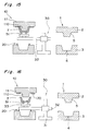
- a vacuum molding means as another preforming means 10 is constituted of a preforming die composed of a lower core die 15 having a projecting part 150 and an upper cavity die 16 and, the vacuum suction means 14 for sucking the material 7 through vacuum suction holes 15a (referring to Figs. 8A-8C).
- the projecting part 150 is generally matched in shape with the cavity formation face of the injection molding die.
- the patterned insert material 7 with its end parts secured by the clamping means 13 (Fig. 8A) is pressed to the projecting part 150 of the lower core die 15 and heated by a heating means 17 (Fig. 8B) to be in tight contact with the projecting face of the projecting part 150 of the lower core die 15 through vacuum suction to be preformed (Fig. 8C).
- the patterned insert material 7 can be preformed into the shape to be fit onto the projecting cavity formation face 5 of the male die 2 of the injection molding die or on the recessed cavity formation face 6 of the female die 3 thereof.
- the preformed material 7 can be left in the lower core die 15 or in the upper cavity die 16.
- the lower core die 15 is provided with a pneumatic means or an ejector means (not shown), or the upper cavity die 16 is provided with the vacuum suction means 14.
- the heating means 17 such as a heating plate or a hot wind fan (referring to Figs. 7A and 8A-8C) can be arranged to move between the inside and outside of the preforming means 10 to facilitate the preforming of the insert material 7.
- the insert material 7 can be heated from outside of the preforming means 10 as shown in Fig. 7D.
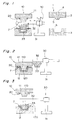
- the trimming means 20 (with reference to Figs. 6A-6C, 7A, 7B, and 8A-8C) trims an unnecessary portion of the insert material 7 so as to prevent the insert material 7 from projecting out from a peripheral edge 61 of the surface of a desired cubic molded article 60 (referring to Figs. 25 and 26).
- the trimming means 20 can be a press cutter with a cutting blade 21 (referring to Figs. 6A-6C and 7A and 7B), a heating cutter (not shown) for cutting off only a required portion, or a laser cutter shown in Fig. 7C.
- the laser cutter has a laser emission head 80 with a laser emission opening which is mounted on an XYZ stage 81 and is made movable optionally in three dimensions, namely, in X, Y, and Z directions.
- the laser cutter is installed above the preforming means 10 of the vacuum molding means composed of the lower cavity die 12 and the vacuum suction means 14.
- Also cutting dies can be employed as the trimming means 20, which uses an edge 15b of the lower core die 15 and an edge 16b of the upper cavity die 16 to perform cutting while the gap between the edges 15b and 16b is set to be opened 0.005-0.03mm wide when the edges 15b and 16b pass each other.
- the above preforming means 10 and trimming means 20 can be constructed separately. Or a means for preforming and trimming which is comprised of a core die with the cutting blade 21 and a cavity die with the vacuum suction means 14 or a cutting die is prepared to perform preforming and trimming of the insert material at one time (referring to Figs. 6A-6C, 7A, 7B, and 8A-8C).
- the preforming means 10 or trimming means 20 can be provided with a feeding means 40 of the patterned insert material (referring to Fig. 9) composed of a rewind roll 41 and a wind roll 42.
- the feeding means 40 is a means for supplying the insert material 7 before the material is preformed or trimmed intermittently by the rewind roll 41 and winding the preformed or trimmed material 7 by the wind roll 42.
- the insert material 7 fed from the rewind roll 41 is preformed or trimmed by the preforming means 10 or trimming means 20, and then a husk 170 is generated from the continuous patterned insert material 7 and the insert material is wound by the wind roll 42.
- the insert material 7 is supplied intermittently while the pattern of the material 7 is correctly positioned to the trimming means 20 by a sensor or the like.
- a laminating means 70 having a heating part or a press part, etc. can be set in the running course of the insert material 7 between a position where the insert material is rewound and a position where the rewound material is supplied into the preforming means 10 or trimming means 20.
- a thick, light-permeable second base material 77 is laminated by the laminating means 70 to the insert material 7 so as to prevent the preformed insert material 7 from losing the shape and so as to have the strength.
- the die 1 is, as shown in Fig. 1, constituted of the male die 2 having the projecting cavity formation face 5 and the female die 3 having the recessed cavity formation face 6.
- the cavity 8 is formed to obtain the desired cubic molded article 60.
- the cubic molded article 60 is, for example, a circular or an oval button-like cubic molded article (referring to Figs.
- the article can be a cubic molded article with a shape having at least the top face 62 and the skirt portion 63 extended generally downward from the periphery of the top face 62 (referring to Fig. 27).
- the resin injection port 4 is opened at the cavity formation face constituted of the projecting cavity formation face 5 and the recessed cavity formation face 6, through which molding resin 9 is injected into the cavity 8 (referring to Fig. 5).
- the resin injection port 4 can be formed at the projecting cavity formation face 5 of the male die 2 (referring to Fig. 1) or at the recessed cavity formation face 6 of the female die 3 (referring to Fig. 15).
- the preformed and trimmed insert material 7 is set at the recessed cavity formation face 6 of the female die 3 and the obtained insert molded article 100 has the patterned insert material 7 formed at a projecting face 66 of the cubic molded article 60 (referring to Fig. 25).
- the preformed and trimmed insert material 7 is fed at the projecting cavity formation face 5 of the male die 2, whereby the insert material 7 is formed at a recessed face 67 of the cubic molded article 60 in the obtained insert molded article 100 (referring to Fig. 26).
- the injection molding die 1 is a die mounted to a vertical injection molding machine so constructed as to inject molding resin perpendicularly.
- the injection molding die 1 can be a die installed in a horizontal injection molding machine which injects molding resin in the horizontal direction, as in Figs. 20-23.
- a transferring/setting means 30 is a means which transfers the preformed and trimmed insert material 7 to the injection molding die 1 to set at the projecting cavity formation face 5 of the male die 2 of the injection molding die or the recessed cavity formation face 6 of the female die 3 thereof.
- the transferring/setting means 30 is composed of a supporting stage 31, a movable arm 32, and a transfer head 33.
- the supporting stage 31 is set at a fixed position to the preforming means 10, trimming means 20, and injection molding die 1.
- the movable arm 32 is set to be turnable about the supporting stage 31 and rotatable about the axis of the movable arm 32, and moreover movable up and down and right and left to the supporting stage 31.
- the transfer head 33 is adapted to move far and close to the movable arm 32.
- the transferring/setting means 30 can be a multi-joint robot.
- the transfer head 33 fixed to the movable arm 32 is able to reciprocate between the set position of either the preforming means 10 or trimming means 20 and the set position of the cavity formation face of the injection molding die 1.
- the transfer head 33 can be directed to the core die or the cavity die within the preforming means 10 or trimming means 20, i.e., in any optional direction.
- the transfer head 33 can be directed in any direction, e.g., to the male die 2 or the female die 3 within the injection molding die 1.
- the transfer head 33 preferably can be provided with a vacuum suction means, a pneumatic means, or suction cups (not shown), etc. to hold or release the preformed and trimmed insert material 7 at the required time.
- the transferring/setting means 30 preferably can be equipped with a take-out means 50 for taking out insert molded articles. It is suitable to provide suction cups 51, a vacuum suction means, a pneumatic means (not shown), or the like at the rear face of the transfer head 33 to hold and release the insert molded article 100 at any time (referring to Fig. 24).
- the insert material 7 having end parts clamped is preformed to almost agree with the shape of the projecting cavity formation face 5 of the male die 2 or the recessed cavity formation face 6 of the female die 3 of the injection molding die 1, and an unnecessary portion of the insert material 7 is trimmed not to bulge out of the peripheral edge 61 of the surface of the desired cubic molded article 60 (referring to Figs. 25 and 26) (referring to Figs. 2, 6A-6C, 7A, 7B, and 8A-8C).
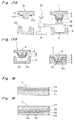
- Such ink layers as a pattern layer 72, an adhesive layer 73, and the like are sequentially laminated on a base material 71 to obtain the insert material 7 (referring to Fig. 18).
- the base material 71 is used as a base film or a base sheet of a general-purpose patterned insert material made of plastic film such as polyethylene terephthalate.
- the pattern layer 72 is formed by a general method, e.g., printing with the use of a light-permeable ink, a light-shielding ink or the like to represent patterns, figures, logotypes, characters, outline types, symbols, etc. on the surface of the molded article 60.
- the pattern layer 72 can have a metallic layer formed through vacuum vapour deposition.
- the adhesive layer 73 works to make the insert material 7 adhere to the surface of the molded article 60 simultaneously with the molding of the article 60. Resin of the same series as that constituting the molded article 60 is used to form the adhesive layer 73 in a general method like printing.
- a light-shielding ink layer of outline types and an adhesive layer are sequentially formed on the base sheet.
- a light-permeable colored ink layer is formed to cover at least the outline types and an adhesive layer is overlaid.
- the outline types are seen with the color of an illuminating light in the former insert material, while the letters are indicated with the color of the light-permeable colored ink layer in the latter insert material.
- the outline types are preferably formed on the base sheet so that the light-shielding ink layer forms the outline types (that is, a portion where the light-shielding ink is not adhered represents a letter).
- the outline types can be in an optional pattern of characters, symbols, patterns, figures, or logotypes, etc.
- a first colored layer 75 with opening parts 78 for outline types to indicate letters or symbols is formed on a first light-permeable base material 74, and a second colored layer 76 having light permeable properties is formed at least on the opening parts 78, which is further covered with a thick second light-permeable base material 77.
- the opening parts 78 produce outline types in an optional pattern of characters, symbols, patterns, figures, logotypes, etc.
- the thick second light-permeable base material 77 is a base material of a film or a sheet formed to provide the appropriate strength to the whole insert material 7 so as to avoid the deformation of the material 7 subsequent to the preforming (referring to Fig. 19). Any material is employable as the patterned insert material 7 so long as it can be preformed and trimmed and tightly held in touch with the molding resin 9.
- the insert material 7 is preferably preformed by the preforming means 10 described earlier. At this time, the insert material 7 can be heated and softened by using the heating means 17 at the pressing time or vacuum molding time so as to facilitate the preforming (referring to Figs. 7A and 8A-8C).
- the patterned insert material 7 to be set at the projecting cavity formation face 5 of the male die 2 having the injection port 4 (referring to Fig. 17B)
- the vacuum molding means composed of the preforming die composed of the lower core die 15 which has the projecting part 150 approximately agreeing with the shape of the cavity formation face of the female die 3 of the injection molding die 1 and the upper cavity die 16, the vacuum suction means 14 and the clamping means 13 for clamping the end parts of the patterned insert material 7 (referring to Figs. 8A-8C), there are two basic preforming methods as follows.
- the material 7 is heated by the heating means 17 and softened, thereby to be brought in touch with the top face of the projecting part 150 of the lower core die 15.
- the insert material 7 is thus preformed to trace the projecting shape of the lower core die 15. A portion of the pattern of the patterned insert material or a portion without the pattern can be brought on the top face of the projecting part 150 of the lower core die 15.
- the top face of the projecting part 150 of the lower core die 15 is set in touch with the insert material 7 beforehand. Thereafter, the insert material 7 is heated and softened by the heating means 17.
- the clamping means 13 can be moved close to the preforming die so as to bring the top face of the projecting part 150 of the lower core die 15 in touch with the insert material 7. Or, the lower core die 15 along with the projecting part can be moved close to the clamping means 13.
- the trimming of the insert material 7 is preferably carried out by the aforementioned trimming means 20.
- the trimming shape of the insert material 7 can be a shape not protruding from the peripheral edge 61 of the surface of the desired cubic molded article 60 obtained by the injection molding die 1 or a shape protruded therefrom. More specifically, in the case where the cubic molded article 60 is a button-like cubic molded article having the top face 62 and the skirt portion 63 of a circular truncated cone (referring to Figs.
- the trimming shape of the insert material 7 is such a shape that the material 7 covers the top face 62 and the skirt portion 63 of the article 60 and at the same time, not to protrude from the peripheral edge 61 of the skirt portion 63 in the shape like a tongue (referring to Figs. 25 and 26).
- the trimming shape of the insert material 7 is such a shape as to cover the light-permeable cubic molded article 60 in a manner not to project from the flange portion 64 or the second skirt portion 65 (referring to Fig. 27).
- the insert material 7 can be preformed and trimmed in separate steps or simultaneously by one means (referring to Figs. 6A-6C, 7A, 7B, and 8A-8C).
- the insert material 7 can be intermittently supplied to the preforming means 10 or trimming means 20 by using the feeding means 40 comprised of the rewind roll 41 and the wind roll 42 (referring to Fig. 9).
- the base material 77 may be too hard to wind up in a roll.
- the second light-permeable base material 77 is laminated by a laminating means 70 or the like before the insert material 7 without the second light-permeable base material 77 reaches the preforming means 10 or trimming means 20 (referring to Fig. 9) after rewound from the rewind roll 41, and then, the material 7 is preformed and trimmed and wound by the wind roll 42 (referring to Fig. 9), preferably.
- the preformed and trimmed insert material 7 is transferred to the injection molding die 1 and then set at the cavity formation face of the male die 2 or female die 3 of the injection molding die 1 (referring to Figs. 3-5, Figs. 10-14, 15, 16, 17A, 17B, and 20-23).
- the cavity formation face is the projecting cavity formation face 5 of the male die 2 and the recessed cavity formation face 6 of the female die 3.
- the above transferring and setting operation of the preformed and trimmed insert material 7 may be performed by the transferring/setting means 30 composed of the supporting base 31, movable arm 32, and transfer head 33 as depicted earlier.
- the transfer head 33 is brought close to the recessed part of the lower cavity die 12 of the preforming means 10 to hold the insert material 7 by the transfer head 33 (referring to Fig. 3). Then, the movable arm 32 is rotated 180° about the supporting stage 31 to set the transfer head 33 to face to the recessed cavity formation face 6 of the injection molding die 1 (referring to Fig. 4).
- the insert molded article 100 left at the projecting cavity formation face 5 is caught by the take-out means 50 arranged at the rear side of the transfer head 33 (referring to Fig. 24), and the transfer head 33 is retreated from within the injection molding die 1 in order to prepare for a next transfer (referring to Fig. 5).
- the transfer head 33 directed upward is brought close to the recessed part 160 of the upper cavity die 16 of the preforming means 10 to hold the insert material 7 by the transfer head 33 (referring to Figs. 10 and 11).
- the transfer head 33 is subsequently rotated 180° about the axis of the movable arm 32 to face downward (referring to Fig. 12).
- the movable arm 32 is turned 180° about the supporting stage 31 (referring to Fig. 13), so that the transfer head 33 is set facing to the recessed cavity formation face 6 of the injection molding die 1 (referring to Fig. 14).
- the transfer head 33 is retracted from inside the injection molding die 1 to make preparation for a next transfer.
- the upturned transfer head 33 is moved close to the projecting part 110 of the upper core die 11 of the preforming means 10 thereby to hold the insert material 7 by the suction cups 51 provided in the transfer head 33 (referring to Figs. 15 and 16).
- the movable arm 32 is turned 180° around the supporting stage 31 to move the transfer head 33 to confront the projecting cavity formation face 5 of the injection molding die 1 (referring to Fig. 17A).
- the transfer head 33 is then retreated from within the injection molding die 1 to make preparation for a next transfer.
- the transfer head 33 When the insert material 7 left at the recessed part 120 of the lower cavity die 12 of the preforming means 10 is transferred and set to the recessed cavity formation face 6 of the injection molding die 1 set in the horizontal injection molding machine (referring to Figs. 20-23), the transfer head 33 is moved close to the recessed part 120 of the lower cavity die 12 of the preforming means 10 to hold the insert material 7 by the transfer head 33 (referring to Figs. 20 and 21). Then, the transfer head 33 is rotated 90° centering the shaft of the movable arm 32 to be laid (referring to Fig. 22). The movable arm 32 is turned 180° around the supporting stage 31 to set the transfer head 33 to confront the recessed cavity formation face 6 of the injection molding die 1 (referring to Fig. 23).
- the insert molded article 100 remaining at the projecting cavity formation face 5 is held by the take-out means 50 set at the rear face of the transfer head 33 (referring to Fig. 24).
- the transfer head 33 is then retreated from inside the injection molding die 1 to make preparation for a next transfer.
- the patterned insert material 7 is preformed beforehand to approximately agree with the recessed cavity formation face 6 of the female die 3 or projecting cavity formation face 5 of the male die 2, it can be set at a predetermined position only by being fitted in the recessed cavity formation face 6 of the female die 3 or projecting cavity formation face 5 of the male die 2.
- the male and female dies 2 and 3 are clamped to form the cavity 8, and the molding resin 9 is injected into the cavity 8 (referring to Fig. 5).
- the molded article 100 in which the insert material 7 is formed on the surface of the article 60 is removed from the injection molding die 1.
- the article 100 can be removed therefrom by the take-out means 50 set at the rear side of the transfer head 33 or the like means.
- the adhesive layer of the insert material 7 is melted by the heat of the resin when the molding resin 9 is injected. As the molding resin 9 is cooled and solidified, the adhesive layer is bonded to the surface of the article 60.
- the molding resin 9 is composed of resin such as acrylonitrile styrene, polycarbonate, polystyrene, acryl, or polyester.
- the present invention in the above-described constitution and operation displays such effects as follows.
- the patterned insert material is preformed so as to correspond in shape to the cavity formation face of the male or female die of the injection molding die, and an unnecessary portion of the insert material is trimmed not to project from the peripheral edge of the surface of a cubic molded article before the patterned insert material is set in the injection molding die. Therefore, it is prevented that the film refuse is adhered to or accumulated at the surface of the injection molding die or mingles with the molten resin.
- the insert molded articles can be produced with a high yield. Moreover, it can be also effectively prevented that a broken piece of the blade when the insert material is cut enters the injection molding die or the insert material is not properly cut.
- the insert material is preformed to correspond to the cavity formation face of the male or female die of the injection molding die, it is not necessary to form a notch in the insert material even if the cavity formation face of the male or female die of the injection molding die has a three-dimensional shape. Accordingly, the molding resin is prevented from leaking through the notch to adhere to the surface of the insert material. Without the notch, moreover, the beauty of the molded article is never lost.
- the portion of the insert material corresponding to the top face of an insert molded article is brought in touch with the top face of the projecting part of the preforming die, the portion is expanded considerably little in the processes afterwards.
- the insert material is softened at this time by the heat, the portion in touch with the top face of the projecting part of the preforming die tends to be less softened than the portion not in touch with the top face, and therefore, the former portion is further little expanded although the latter portion not in touch with the top face is stretched through vacuum suction. As a result of this, the generation of wrinkles, the positional shirt the deformation or break of the ink layers can be effectively prevented.
- the preformed insert material can be directly set at the cavity formation face of the die of the male and female dies of the injection molding die which is not provided with the resin injection port. Therefore, since the insert material is not necessary to be pressed from one die to the other die by the pressure of the molding resin, the insert material is prevented from being deformed, wrinkled or shifted in position.
Landscapes
- Engineering & Computer Science (AREA)
- Manufacturing & Machinery (AREA)
- Mechanical Engineering (AREA)
- Injection Moulding Of Plastics Or The Like (AREA)
- Processing And Handling Of Plastics And Other Materials For Molding In General (AREA)
Applications Claiming Priority (5)
| Application Number | Priority Date | Filing Date | Title |
|---|---|---|---|
| JP35826792 | 1992-12-27 | ||
| JP358267/92 | 1992-12-27 | ||
| JP85482/93 | 1993-03-18 | ||
| JP8548293A JPH06270199A (ja) | 1993-03-18 | 1993-03-18 | インサート成形品製造装置とインサート成形品製造方法 |
| PCT/JP1993/001903 WO1994014590A1 (en) | 1992-12-27 | 1993-12-27 | Insert molded article, and apparatus and method for producing the insert molded article |
Publications (1)
| Publication Number | Publication Date |
|---|---|
| EP0642910A1 true EP0642910A1 (de) | 1995-03-15 |
Family
ID=26426486
Family Applications (1)
| Application Number | Title | Priority Date | Filing Date |
|---|---|---|---|
| EP94903078A Withdrawn EP0642910A1 (de) | 1992-12-27 | 1993-12-27 | Verfahren und vorrichtung zum herstellen von mit einsätzen versehenen gegenständen sowie mit einsatz versehener gegenstand |
Country Status (4)
| Country | Link |
|---|---|
| US (1) | US5800759A (de) |
| EP (1) | EP0642910A1 (de) |
| CA (1) | CA2130925C (de) |
| WO (1) | WO1994014590A1 (de) |
Cited By (7)
| Publication number | Priority date | Publication date | Assignee | Title |
|---|---|---|---|---|
| EP0894596A2 (de) * | 1997-07-30 | 1999-02-03 | Ford Motor Company | Verfahren und Vorrichtung zum Einlegen einer vorgeformten Folie in eine Form |
| EP1193044A2 (de) * | 2000-09-28 | 2002-04-03 | Yamamoto Kogaku Co., Ltd. | Verfahren zur kontiuierlichen Herstellung von optischen Gegenständen |
| WO2003076162A1 (fr) * | 2002-03-14 | 2003-09-18 | Nissha Printing Co., Ltd. | Moule metallique pour moulage par injection et procede de fabrication d'une partie moulee par injection |
| CN103753759A (zh) * | 2014-01-14 | 2014-04-30 | 昆山易昌泰塑胶有限公司 | 能连续在模内对埋入零件进行加工和埋入注塑的注塑机 |
| CN103950149A (zh) * | 2014-05-21 | 2014-07-30 | 山东大学 | 一种微注塑成型自动嵌取件装置 |
| US9636856B2 (en) | 2013-05-15 | 2017-05-02 | Toshiba Kikai Kabushiki Kaisha | Molding system and method of manufacturing molded article |
| CN109203357A (zh) * | 2018-09-14 | 2019-01-15 | 湖南镭目科技有限公司 | 一种副枪探头测温支架及其加工方法 |
Families Citing this family (26)
| Publication number | Priority date | Publication date | Assignee | Title |
|---|---|---|---|---|
| US5783228A (en) * | 1996-02-05 | 1998-07-21 | Crx Limited | Molded and laminated curved surface composites |
| TW580426B (en) * | 1999-06-29 | 2004-03-21 | Four Pillars Entpr Co Ltd | Method for processing a film |
| FR2806349B1 (fr) * | 2000-03-20 | 2002-12-06 | Plastic Omnium Cie | Procede de fabrication d'une piece en matiere plastique renforcee |
| FI20002038A (fi) * | 2000-09-15 | 2002-03-16 | Nokia Mobile Phones Ltd | Koristeltu ruiskupuristettu tuote ja menetelmä sen valmistamiseksi |
| US6659750B1 (en) | 2000-11-01 | 2003-12-09 | Omnimold, Llc | Blow mold with removable inserts |
| NL1021837C2 (nl) * | 2002-11-05 | 2004-05-07 | Fountain Patents B V | Matrijs en werkwijze voor de vervaardiging van houders zoals kuipvormige containers. |
| US20050175726A1 (en) * | 2004-02-06 | 2005-08-11 | Deng-Min Yang | Forming apparatus for forming a foamed body from a foamable plastic material under pressure control |
| DE102004036171A1 (de) * | 2004-07-26 | 2006-03-23 | Angell-Demmel Gmbh | Verfahren und Vorrichtung zur Herstellung eines Dekor-Zierteils mit freigestelltem Symbol |
| US7478854B2 (en) | 2004-10-19 | 2009-01-20 | International Automotive Components Group North America, Inc. | Automotive handle with soft feel and method of making the same |
| US7458631B2 (en) | 2004-10-19 | 2008-12-02 | International Automotive Components Group North America, Inc. | Automotive armrest with soft feel and method of making the same |
| KR101298795B1 (ko) * | 2005-09-30 | 2013-08-22 | 다이니폰 인사츠 가부시키가이샤 | 화장 시트 및 그의 제조 방법 및 화장 시트 부착 사출성형품 |
| US7950441B2 (en) * | 2007-07-20 | 2011-05-31 | GM Global Technology Operations LLC | Method of casting damped part with insert |
| US20090191343A1 (en) * | 2008-01-30 | 2009-07-30 | Aiska International Co., Ltd. | Method for printing decorative member |
| TWI383880B (zh) * | 2008-03-28 | 2013-02-01 | Fih Hong Kong Ltd | 注塑模具及應用其製造殼體之方法 |
| CN101850591A (zh) * | 2009-04-06 | 2010-10-06 | 康准电子科技(昆山)有限公司 | 模内装饰成型方法及模制品 |
| BR112013024241B1 (pt) * | 2011-03-21 | 2021-07-20 | Luxottica S.R.L. | Processo para fabricar armações de óculos, equipamento para fabricar armações de óculos e armação de óculos decorada |
| DE102011103824B4 (de) * | 2011-06-01 | 2024-02-01 | Leonhard Kurz Stiftung & Co. Kg | Verfahren zur Herstellung In-Mould-dekorierter Kunststoffformteile |
| DE102011121903A1 (de) * | 2011-12-21 | 2013-06-27 | Volkswagen Aktiengesellschaft | Verfahren zur Herstellung eines Verbundbauteils |
| CN102717485A (zh) * | 2012-06-25 | 2012-10-10 | 佛山市南海华达模具塑料有限公司 | 一种复合贴面注塑模具及其成型工艺 |
| DE102012106936A1 (de) | 2012-07-30 | 2014-01-30 | International Automotive Components Group Gmbh | Integrierte Kontaktheizung für thermoplastisch gebundene Matten im Spritzgießwerkzeug |
| US10315368B2 (en) * | 2013-05-06 | 2019-06-11 | Dow Global Technologies Llc | Forming tool with integral cutting for composite material |
| US10446728B2 (en) * | 2014-10-31 | 2019-10-15 | eLux, Inc. | Pick-and remove system and method for emissive display repair |
| US9695289B1 (en) * | 2016-03-15 | 2017-07-04 | Doskocil Manufacturing Company, Inc. | Bulk molding compound-based pet bowl |
| CN110461567A (zh) * | 2017-04-04 | 2019-11-15 | 大日本印刷株式会社 | 基材保持机构、运送装置、保持部件、基材成形系统、基材保持方法和基材成形方法 |
| WO2020160942A1 (en) | 2019-02-06 | 2020-08-13 | Basf Se | Method for producing an insert-molded article |
| US11794376B2 (en) * | 2021-03-31 | 2023-10-24 | The Boeing Company | Application of gap fillers during layup of charges of composite material |
Family Cites Families (17)
| Publication number | Priority date | Publication date | Assignee | Title |
|---|---|---|---|---|
| JPS6037772B2 (ja) * | 1980-12-17 | 1985-08-28 | 松下電器産業株式会社 | 複合成形金型 |
| JPS59202834A (ja) * | 1983-05-06 | 1984-11-16 | Yoshida Kogyo Kk <Ykk> | 装飾体の製造方法 |
| JPH0684031B2 (ja) * | 1984-08-16 | 1994-10-26 | 三菱マテリアル株式会社 | 射出成形方法 |
| JPS6241011A (ja) * | 1985-08-16 | 1987-02-23 | Dainippon Printing Co Ltd | 電磁波シ−ルド成形品の製造方法 |
| DE3767777D1 (de) * | 1986-06-11 | 1991-03-07 | Peerless Plastics Packaging | Herstellung geformter kunststoffkoerper. |
| JPH0753429B2 (ja) * | 1986-10-23 | 1995-06-07 | 三菱樹脂株式会社 | 複合容器の製造方法 |
| US4755129A (en) * | 1987-03-09 | 1988-07-05 | Mobil Oil Corporation | Trim in place thermoforming arrangement for plastic articles |
| JPS63268612A (ja) * | 1987-04-27 | 1988-11-07 | Tokai Rubber Ind Ltd | 自動車車体装飾用複合モ−ルの製法 |
| US5195162A (en) * | 1987-12-16 | 1993-03-16 | General Motors Corporation | Planar polymer light guide methods and apparatus |
| JPH0777740B2 (ja) * | 1987-12-21 | 1995-08-23 | 日本プラスト株式会社 | 表皮体を有する合成樹脂製品の製造方法 |
| GB8802738D0 (en) * | 1988-02-06 | 1988-03-09 | British Aerospace | Apparatus & method for fabricating superplastically formed structures |
| JPH078514B2 (ja) * | 1988-04-18 | 1995-02-01 | ダイセル化学工業株式会社 | 光ディスク用プラスチック基板の射出成形法 |
| US5221232A (en) * | 1989-01-12 | 1993-06-22 | Zero-Max, Inc. | Flexible disc-like coupling element |
| US5196152A (en) * | 1989-12-12 | 1993-03-23 | The Dow Chemical Company | Reaction injection molding method with internal frame and shear edge |
| JPH0410923A (ja) * | 1990-04-27 | 1992-01-16 | Dainippon Printing Co Ltd | 金属蓋付容器の製造方法 |
| US5271882A (en) * | 1990-11-09 | 1993-12-21 | Tokai Kogyo Kabushiki Kaisha | Blow molding process with sheet interposed between mold and product being molded |
| US5128091A (en) * | 1991-02-25 | 1992-07-07 | Xerox Corporation | Processes for forming polymeric seamless belts and imaging members |
-
1993
- 1993-12-27 US US08/295,663 patent/US5800759A/en not_active Expired - Lifetime
- 1993-12-27 EP EP94903078A patent/EP0642910A1/de not_active Withdrawn
- 1993-12-27 CA CA002130925A patent/CA2130925C/en not_active Expired - Lifetime
- 1993-12-27 WO PCT/JP1993/001903 patent/WO1994014590A1/ja not_active Application Discontinuation
Non-Patent Citations (1)
| Title |
|---|
| See references of WO9414590A1 * |
Cited By (15)
| Publication number | Priority date | Publication date | Assignee | Title |
|---|---|---|---|---|
| EP0894596A2 (de) * | 1997-07-30 | 1999-02-03 | Ford Motor Company | Verfahren und Vorrichtung zum Einlegen einer vorgeformten Folie in eine Form |
| EP0894596A3 (de) * | 1997-07-30 | 1999-05-26 | Ford Motor Company | Verfahren und Vorrichtung zum Einlegen einer vorgeformten Folie in eine Form |
| US6221304B1 (en) | 1997-07-30 | 2001-04-24 | Visteon Global Technologies, Inc. | Method of manufacturing a film coated article |
| US6814902B2 (en) | 2000-09-28 | 2004-11-09 | Yamamoto Kogaku Co. LTD | Method for continuously manufacturing optical article |
| EP1193044A3 (de) * | 2000-09-28 | 2004-01-28 | Yamamoto Kogaku Co., Ltd. | Verfahren zur kontiuierlichen Herstellung von optischen Gegenständen |
| EP1193044A2 (de) * | 2000-09-28 | 2002-04-03 | Yamamoto Kogaku Co., Ltd. | Verfahren zur kontiuierlichen Herstellung von optischen Gegenständen |
| KR100812092B1 (ko) * | 2000-09-28 | 2008-03-12 | 야마모토 고가쿠 가부시키가이샤 | 광학 물품의 연속 제조방법 |
| WO2003076162A1 (fr) * | 2002-03-14 | 2003-09-18 | Nissha Printing Co., Ltd. | Moule metallique pour moulage par injection et procede de fabrication d'une partie moulee par injection |
| US9636856B2 (en) | 2013-05-15 | 2017-05-02 | Toshiba Kikai Kabushiki Kaisha | Molding system and method of manufacturing molded article |
| US10093048B2 (en) | 2013-05-15 | 2018-10-09 | Toshiba Kikai Kabushiki Kaisha | Molding system and method of manufacturing molded article |
| CN103753759A (zh) * | 2014-01-14 | 2014-04-30 | 昆山易昌泰塑胶有限公司 | 能连续在模内对埋入零件进行加工和埋入注塑的注塑机 |
| CN103950149A (zh) * | 2014-05-21 | 2014-07-30 | 山东大学 | 一种微注塑成型自动嵌取件装置 |
| CN103950149B (zh) * | 2014-05-21 | 2016-01-20 | 山东大学 | 一种微注塑成型自动嵌取件装置 |
| CN109203357A (zh) * | 2018-09-14 | 2019-01-15 | 湖南镭目科技有限公司 | 一种副枪探头测温支架及其加工方法 |
| CN109203357B (zh) * | 2018-09-14 | 2020-10-02 | 湖南镭目科技有限公司 | 一种副枪探头测温支架及其加工方法 |
Also Published As
| Publication number | Publication date |
|---|---|
| WO1994014590A1 (en) | 1994-07-07 |
| CA2130925A1 (en) | 1994-07-07 |
| US5800759A (en) | 1998-09-01 |
| CA2130925C (en) | 2002-06-11 |
Similar Documents
| Publication | Publication Date | Title |
|---|---|---|
| US5800759A (en) | Insert molded article, and apparatus and method for producing the insert molded article | |
| US6475423B1 (en) | Hybrid injection molding process for enhancing exterior appearance of molded articles by molding fabric thereto | |
| EP0782908B1 (de) | Foliendekorierende Spritzgussmaschine und foliendekorierendes Spritzgussverfahren | |
| JPH0768588A (ja) | 成形されたアップリケ製品の製造法 | |
| JP2711629B2 (ja) | インサート成形品とその製造方法 | |
| JPH06270199A (ja) | インサート成形品製造装置とインサート成形品製造方法 | |
| JP2967927B1 (ja) | インサート成形品の製造装置とインサート成形品の製造方法 | |
| JPH07227877A (ja) | 射出成形同時絵付方法及び装置 | |
| EP0451447A1 (de) | Verfahren zur Herstellung von geformten Kunststoffartikeln | |
| JP2824295B2 (ja) | 加飾シートで被覆された合成樹脂製品の成形方法及びその装置 | |
| JP3109726B2 (ja) | ラベル付容器及びその製造方法。 | |
| JP2527619B2 (ja) | 外面が非平滑状の合成樹脂製容器とその製造方法 | |
| JP3180851B2 (ja) | インサート成形金型とインサート成形品の製造方法 | |
| JP2824298B2 (ja) | 加飾シートで被覆された合成樹脂製品の成形方法及びその装置 | |
| JPH07156196A (ja) | インサートシートとインサート成形品の製造方法 | |
| JP3003678B1 (ja) | プレフォーム用金型およびフィルムインサート成形品の製造方法 | |
| JPH02309385A (ja) | ホログラム形成合成樹脂成形品及びその製造方法 | |
| JP3546168B2 (ja) | フィルムトリミング装置 | |
| JP3150804B2 (ja) | インサート成形金型とインサート成形品の製造方法 | |
| JPH11277568A (ja) | クランプ装置とそれを用いたフィルムインサート成形品の製造方法 | |
| JPS6295209A (ja) | 加飾成形装置及び該装置を用いた絵付成形品の製造方法 | |
| JP2512764Y2 (ja) | ラベル付容器成形用金型 | |
| JPH08300380A (ja) | 加飾表皮材により部分的に加飾されたシート状樹脂成形体の製造方法 | |
| JP3748670B2 (ja) | 立体絵柄を有する樹脂成形品及びその製造方法 | |
| JPH08216183A (ja) | 射出成形同時絵付け方法及びそれに用いる金型 |
Legal Events
| Date | Code | Title | Description |
|---|---|---|---|
| PUAI | Public reference made under article 153(3) epc to a published international application that has entered the european phase |
Free format text: ORIGINAL CODE: 0009012 |
|
| AK | Designated contracting states |
Kind code of ref document: A1 Designated state(s): DE FR GB IT |
|
| STAA | Information on the status of an ep patent application or granted ep patent |
Free format text: STATUS: THE APPLICATION HAS BEEN WITHDRAWN |
|
| 18W | Application withdrawn |
Withdrawal date: 19950313 |