EP0636538B1 - Elektromotorischer Hilfsantrieb für Fahrzeug, insbesondere Fahrrad - Google Patents
Elektromotorischer Hilfsantrieb für Fahrzeug, insbesondere Fahrrad Download PDFInfo
- Publication number
- EP0636538B1 EP0636538B1 EP94111666A EP94111666A EP0636538B1 EP 0636538 B1 EP0636538 B1 EP 0636538B1 EP 94111666 A EP94111666 A EP 94111666A EP 94111666 A EP94111666 A EP 94111666A EP 0636538 B1 EP0636538 B1 EP 0636538B1
- Authority
- EP
- European Patent Office
- Prior art keywords
- electric power
- assisted vehicle
- power assisted
- planetary
- output shaft
- Prior art date
- Legal status (The legal status is an assumption and is not a legal conclusion. Google has not performed a legal analysis and makes no representation as to the accuracy of the status listed.)
- Expired - Lifetime
Links
Images


Classifications
-
- B—PERFORMING OPERATIONS; TRANSPORTING
- B62—LAND VEHICLES FOR TRAVELLING OTHERWISE THAN ON RAILS
- B62M—RIDER PROPULSION OF WHEELED VEHICLES OR SLEDGES; POWERED PROPULSION OF SLEDGES OR SINGLE-TRACK CYCLES; TRANSMISSIONS SPECIALLY ADAPTED FOR SUCH VEHICLES
- B62M6/00—Rider propulsion of wheeled vehicles with additional source of power, e.g. combustion engine or electric motor
- B62M6/40—Rider propelled cycles with auxiliary electric motor
- B62M6/45—Control or actuating devices therefor
-
- B—PERFORMING OPERATIONS; TRANSPORTING
- B62—LAND VEHICLES FOR TRAVELLING OTHERWISE THAN ON RAILS
- B62M—RIDER PROPULSION OF WHEELED VEHICLES OR SLEDGES; POWERED PROPULSION OF SLEDGES OR SINGLE-TRACK CYCLES; TRANSMISSIONS SPECIALLY ADAPTED FOR SUCH VEHICLES
- B62M11/00—Transmissions characterised by the use of interengaging toothed wheels or frictionally-engaging wheels
- B62M11/04—Transmissions characterised by the use of interengaging toothed wheels or frictionally-engaging wheels of changeable ratio
- B62M11/14—Transmissions characterised by the use of interengaging toothed wheels or frictionally-engaging wheels of changeable ratio with planetary gears
-
- B—PERFORMING OPERATIONS; TRANSPORTING
- B62—LAND VEHICLES FOR TRAVELLING OTHERWISE THAN ON RAILS
- B62M—RIDER PROPULSION OF WHEELED VEHICLES OR SLEDGES; POWERED PROPULSION OF SLEDGES OR SINGLE-TRACK CYCLES; TRANSMISSIONS SPECIALLY ADAPTED FOR SUCH VEHICLES
- B62M6/00—Rider propulsion of wheeled vehicles with additional source of power, e.g. combustion engine or electric motor
- B62M6/40—Rider propelled cycles with auxiliary electric motor
- B62M6/55—Rider propelled cycles with auxiliary electric motor power-driven at crank shafts parts
-
- F—MECHANICAL ENGINEERING; LIGHTING; HEATING; WEAPONS; BLASTING
- F16—ENGINEERING ELEMENTS AND UNITS; GENERAL MEASURES FOR PRODUCING AND MAINTAINING EFFECTIVE FUNCTIONING OF MACHINES OR INSTALLATIONS; THERMAL INSULATION IN GENERAL
- F16H—GEARING
- F16H37/00—Combinations of mechanical gearings, not provided for in groups F16H1/00 - F16H35/00
- F16H37/02—Combinations of mechanical gearings, not provided for in groups F16H1/00 - F16H35/00 comprising essentially only toothed or friction gearings
- F16H37/021—Combinations of mechanical gearings, not provided for in groups F16H1/00 - F16H35/00 comprising essentially only toothed or friction gearings toothed gearing combined with continuous variable friction gearing
Definitions
- This invention relates to an electrically power assisted vehicle, specifically bicycle as indicated in the preaable of claim 1.
- an electric motor powered by a battery and controller arrangement for assisting the operator effort in response to the pedal input force so as to make the riding of the bicycle easier while at the same time maintaining its ability to provide exercise for the rider.
- a gear reduction unit so as to reduce the speed and increase the power output of the electric motor for transmission to the driven wheel.
- a planetary transmission is employed between the motor output shaft and the drive for the rear wheel so as to provide this speed reduction.
- one way clutches are interposed between both the electric motor and the rear wheel and between the crank mechanism and the rear wheel drive so as to facilitate the transmission of power and not to transmit power to portions which should not be driven.
- the use of one way clutches requires a pair of elements with one way clutching elements interposed between them.
- the two elements that are interconnected by the one way clutching elements must be maintained so that their axes of rotation are substantially coincident and it is the normal practice to employ a bearing arrangement for this purpose. This obviously adds to the cost and complexity of the arrangement.
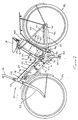
- an electric power assisted bicycle constructed in accordance with an embodiment of this invention is identified generally by the reference numeral 21.
- the bicycle 21 is comprised of a frame assembly, indicated generally by the reference numeral 22, which is comprised of a head pipe 23 that dirigibly journals a front wheel 24 by means of a fork assembly 25.
- a handlebar 26 is affixed to the upper end of the fork assembly 25 in a well known manner for steering of the front wheel 24.
- the frame assembly 22 further includes a downwardly inclined main frame tube 27 that extends rearwardly and downwardly from the head pipe 23 and which terminates at its lower end in a connecting piece 28.
- the connecting piece 28 has affixed to it a seat pilar 29 upon which a saddle-type seat 31 is connected in a manner which will be described.
- the connecting piece 28 is also connected to the upper end of a transmission and pedal support case 32 which journals a crankshaft 33 in a manner which will be described from which a pair of crank arms 34 extend on opposite sides of the case 32.
- Pedals 35 are journalled at the outer ends of the crank arms 34 in a known manner.
- the axis of rotation of the crankshaft 33 is disposed generally transversely of the frame assembly 22.
- a rear wheel 36 is journalled for rotation from the frame assembly 22 by means of a rear arm 37 that is connected to a bracket 38 which is suitable affixed to the case 32 and a pair of back stays 39 which extend from the flattened ends 41 of the yoke 37 and which are connected at their upper ends to the seat pilar 29.
- crank assembly and specifically the crankshaft 33 drives a sprocket, to be described, which in turn drives the rear wheel 36 through a chain 42.
- the chain 42 is encompassed by a chain guard 43 that is affixed to the frame assembly 27 and one of the back stays 39 at one side of the bicycle 21.
- the bicycle 21 is also provided with an electric power assist mechanism which includes an electric motor 43 which is mounted in a manner to be described beneath the main frame tube 27 and thus maintains a low center of gravity.
- the electric motor 43 receives electrical power from a pair of batteries 44 that are contained within a battery case 45 that is mounted, in a manner to be described, to the rear of and extending parallel to the seat pilar 29.
- the seat 31 is movable, in a manner which will be described, so as to access the batteries 44 for replacement and/or service.
- the batteries 44 supply power to the electric motor 43 through a controller, indicated generally by the reference numeral 46, and which is mounted on the underside of the main frame tube 27 forwardly and above the electric motor 43.
- the controller 46 is powered by the batteries 45 through a main switch 47 that is affixed to the underside of the main tube 27 adjacent the head pipe 23.
- the forward positioning of the electric motor 43 and controller 46 relative to the axis of the crank 33 and the rearward positioning of the batteries 44 and battery case 45 relative to this axis provides substantially equal fore and aft balance so as to maintain the stability of the bicycle 21. Also, the components are mounted relatively low so as to maintain a low center of gravity while not being so low as to provide reduced ground clearance.
- the electric motor 43 and controller 44 are enclosed partially within a case assembly 48 that is comprised of an upper member 49 and a lower member 51 which are affixed to each other in any known manner. These members are provided with an opening through which a portion of the controller 46 extends, as indicated by the bracket 52 in Figure 1 so as to permit cooling air flow over components of the controller 46 which should be maintained at relatively low temperatures.
- a sprocket 53 which is driven from either the crank 33 or electric motor 43 in a manner to be described appears in Figure 2 and drives the aforenoted chain 42 for driving the rear wheel 36.
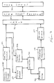
- the driving system will be described by reference to Figure 3 which shows the various components schematically.
- the manual pedal power exerted by the operated seated on the seat 31 on the pedals 35 and crank arms 34 is transmitted through a one-way clutch, indicated schematically at 54 to the sprocket 53 and chain 42.
- the chain 42 is, in turn, drivably coupled to the rear wheel 36 by means of a free-wheeling mechanism, shown schematically at 55, which may also comprise a one-way clutch.
- the electric motor 43 drives a planetary transmission or other speed-reducing transmission, shown schematically at 56, which in turn, also drives the sprocket 53 through a one-way clutch, indicated schematically at 57.
- the controller 46 operates the electric motor 43 in accordance with a system to provide power assist for driving the rear wheel 36 with the amount of power assist being determined, at least in part, by the force exerted by the operator on the pedals 35.
- This arrangement incorporates a speed sensor, indicated generally at 58 and shown in block form in this figure, and a torque sensor, indicated generally at 59, and also shown in block form.
- Figure 5 shows how an electric motor, indicated generally by the reference numeral 201, is coupled to a speed reducer transmission, indicated generally by the reference numeral 202, which is, in turn, then connected to an outer housing 203 of the driven element, such as the housing assembly 32 in this embodiment.
- the electric motor 201 is provided with an outer housing 204 having a front face 205 through which a splined output shaft 206 extends.
- the output shaft 206 of the motor 201 is coupled to an input shaft (not shown) of the transmission 202 so as to drive an output shaft 207 that extends through a rear face 208 of its outer housing 209.
- the outer housing 209 is provided with a recess 211 into which the front face 205 of the electric motor 201 must be assembled.
- the shaft 207 must be connected to a shaft (not shown) in the final drive housing 203, and the transmission housing 209 is received in a recess 212 of this housing.
- the construction of the prior art Provides not only a rather elongated construction due to the assembly of several housings and components with each other, but also presents a problem of aligning a number of shafts and supporting housings with each other.
- One feature of the construction avoids this arrangement, and this will now be described in detail by particular reference to Figures 4, 6 and 8, wherein the electric motor 43 and its integral speed reduction transmission is shown in more detail.
- the motor 43 has an outer housing 61 which, in turn, has a rear face 62 through which the electric motor output shaft 63 extends.
- the transmission 56 shown schematically in Figure 4, is illustrated in detail in Figures 6 and 8, and includes a plurality of planetary frictional elements 64 that are journalled on carrier shaft 65 by intermediate anti-friction bearings 66. These planetary frictional elements 64 are held in tight frictionally engagement with the outer periphery of the electric motor output shaft 63 upon assembly in a manner which will be described. As a result, there will be established a driving relationship between the motor shaft 63 and the planetary frictional elements 64.
- the planetary frictional elements 64 are also engaged within a cylindrical interior of a fixed frictional orbit ring member 67 that has a pair of end plates 68 and 69 and which are affixed to the motor end face 62 by a plurality of threaded fasteners 69. It is to be understood in actual assembly the orbit element 67 and end plates 68 and 69 are affixed to the electric motor housing 61 before its assembly onto the remainder of the construction, which will be described.
- the housing 32 is made up of a first member 72 to which a cover plate 73 is affixed.
- the housing member 72 has a generally cylindrical portion that encircles the orbit ring element 67 and also which encircles a carrier element 74 which has a plurality of bores 75 for receiving the carrier pins 65 on which the planetary elements 64 rotate.
- a ball-type thrust bearing 76 is loaded between the end of the motor output shaft 63 and the front face of the carrier 74 so as to provide axial alignment.
- a pinion shaft 77 is rotatably journalled in the housing piece 72 by means of a pair of ball bearings 78 and engages a thrust bearing 79 which, in turn, engages the back face of the carrier 74.
- a one-way clutch 81 is interposed between the inner periphery of the carrier member 74 and the pinion shaft 77.
- the one-way clutch 81 is of a type which permits the insertion of the pinion shaft 77 into it in an axial direction without interference, but which, when assembled, permits the drive to be transmitted from the carrier member 74 to the pinion shaft, but does not permit the pinion shaft 77 to drive the carrier member 74.
- Any known type of one-way clutch may be employed, but one embodying roller-type clutching elements will permit the ease of assembly.
- the area of the housing member 72 rearwardly of the portion where the carrier 74 and bearing 78 is positioned is provided with a further cavity that receives, among other things, the crankshaft 33 of the pedal assembly.
- This crankshaft is journalled for rotation within this cavity with the ends extending outwardly therefrom for connection to the crank arms 34 in a manner which will be described.
- the pinion shaft 77 is formed with an integral pinion gear which meshes with a ring gear 83.
- the ring gear 83 is, in turn, affixed to a hub 84 that is journalled within the housing member 72 by means of a ball bearing assembly 85.
- the hub 84 is connected to the pinion gear 83 by means of fasteners or rivets 86.
- the sprocket 53 has a splined connection to the hub 84 by means of splines 87 so that when the ring gear 83 rotates, the sprocket 53 will be driven.
- One end of the crankshaft 33 is journalled within the hub 84 by means of anti-friction bearings 88 with an oil seal 89 being disposed at the outer periphery.
- the opposite end of the crankshaft 33 is rotatably journalled within the cover piece 73 of the housing assembly 32 by means of a further ball bearing assembly 91.
- a planetary transmission indicated generally by the reference numeral 92, is provided for establishing a driving relationship between the crank 33 and the ring gear 83, and this connection also includes a one-way clutch.
- This one-way clutch is shown in most detail in Figure 7, and in addition to acting as a one-way clutch, it provides a bearing arrangement for ensuring a coaxial relationship of the various elements of the one-way clutch and thus avoids the necessity of separate bearing elements to maintain the inner and outer races of the one-way clutch in their relationship.
- FIG. 10 and 11 Such a prior art type of one-way clutch and bearing assembly is shown in Figures 10 and 11 wherein there is provided a driving connection between an inner hub 211 and an outer member such as a sprocket 212.
- the inner hub 211 has affixed for rotation with it an inner member 213 that pivotally supports a plurality of pawls 214 in pockets 215.
- pawls 214 are normally biased outwardly by spring arrangement into receptive recesses 216 formed integrally within the interior of the sprocket 212 so as to establish a driving relationship in the counterclockwise direction as seen in Figure 2 but to permit the sprocket 212 to overrun the hub 211 under some conditions.
- Ball bearings 217 are interposed in races formed between the hub 211 and a threaded end piece 218 and in the sprocket 212. As a result, it is necessary to provide a complicated assembly arrangement for maintaining the desired relative rotational axes between the hub 211 and sprocket 212 which adds significantly to the cost and complexity of the assembly.
- This one-way clutch assembly 93 includes a first or inner element 94 which is formed with female splines so as to receive male splines 95 of the crankshaft 33 so as to form a driving connection between the crankshaft 33 and the first element 94.
- the element 94 is provided with curved pockets 96 that receive the complementary curved cylindrical portions 97 of pawl elements, indicated generally by the reference numeral 98.
- These pawl elements 98 have bifurcated fingers 99 which are formed with slots 101 that are aligned with a corresponding slot 102 formed in the outer periphery of the element 94.
- a retainer spring element 103 is received in these slots 102 and 101 and retains the pawl elements 98 in their positions.
- the shape of the slots 101 is such that the spring 103 biases the pawls 98 to an engaged position as shown in Figures 7 and 9.
- the one-way clutch 93 includes a second or outer member, indicated generally by the reference numeral 104, which is provided with a plurality of recesses 105 that are adapted to receive the pawls 98 and to form a driving relationship between the crank shaft 33 and the member 104.
- These pawl-receiving recesses 105 are formed, however, in such a way as to permit the member 104 to drive or rotate faster than the one-way clutch member 94 for a coasting operation or when pedaling backwards.
- the area between the wedging recesses 105 defines a segmental cylindrical surface 106.
- This surface is engaged by a corresponding segmental cylindrical surface 107 formed by the member 94 by outstanding portions that extend beyond recesses formed by first and second portions 108 and 109 in which the pawls 98 are received on opposite sides of the sockets 96. Because of the extent of the cylindrical segments 107 and 106, there is always full bearing arrangement, albeit less than 360°, around the periphery of the elements 94 and 104. Thus the need for separate bearings for providing this relative support are avoided, and the overall construction is thus simplified.
- the outer one-way clutch element 104 carries a plurality of carrier pins 111 on which planet gears 112 are rotatably journalled. These planet gears 112 engage internal gears of a orbital member 113 which is fixed by the fasteners or rivets 86 for rotation with the ring gear 83. It should be noted that the orbit member 113 has a larger diameter where its internal teeth are formed that are engaged with the planet gears 112 then adjacent the end of the pinion shaft 77 as clearly shown in this figure to maintain a relatively small outer diameter for the entire assembly so that the casing assembly 32 has a smaller diameter than that of the crank arms 34.
- the planet gears 112 are engaged with a sun gear 114 formed by a flange 115 that is affixed axially to the crankshaft 33 but rotatable relative to it.
- the planetary transmission 92 formed by the sun gear 115, planet gears 112 and orbit ring gear 113 provide a speed reduction between the crankshaft 33 and the sprocket 53 upon pedal operation so as to provide a force amplification.
- the sun gear 114 acts primarily as a part of the torque sensor previously indicated in block form in Figure 3 and identified by the reference numeral 59 and identified by this same reference numeral in Figures 4 and 6.
- This torque sensor 59 includes an abutment element 116 that is affixed to a lug 117 formed on the flange 115.
- This abutment element 116 is engaged with a lever 118 that is affixed to a shaft 119 journalled in the housing member 72 on a pair of anti-friction bearings 121.
- the shaft 119 is connected to a wiper of a potentiometer 122 so as to provide an electrical output signal indicative of the degree of rotation of the sun gear 114 and, accordingly, the torque exerted by the operator on the pedal assembly.
- a damper member 123 is engaged by a spring 124 which bears against a plate 125 so as to provide a biasing assembly 126 that acts to hold the lever 118 against rotation, and thus provides the torque measurement.
- An adjustable stop 127 limits the degree of rotation of the lever 118 and sun gear 114 in the clockwise direction as shown in Figure 4. This type of torque sensor is described also in the aforenoted copending applications.
- An electrical conduit 128 conveys the signal from the torque sensor 59 and specifically the potentiometer 122 to the controller 47.
- the speed sensor 58 shown in block form in Figure 3, is comprised of a magnetic element and associated coil that is mounted in the housing piece 72 in proximity to the teeth of the ring gear 83. Hence, upon rotation of the ring gear 83 and sprocket 53, a pulse signal will be transmitted from the speed sensor 58 through a conductor 129 to the controller 46 so as to provide the speed signal required for its control.
- a small cover piece 131 is affixed to a side of the cover 73 by threaded fasteners 132 to protect the various elements and to provide a neat overall assembly.
- the housing piece 72 is provided with a plurality of bost openings 133 that receive fasteners so as to affix the drive assembly to the frame assembly 22 and specifically the bracket 28 thereof.
- the battery case 45 is positioned to the rear of the seat pillar 29 and is also disposed forwardly relative to the wheel 36.
- the battery case 45 is relatively narrow and is contained laterally between a pair of auxiliary seat tubes 134 that are connected to and form a part of the frame assembly 22 to the rear of the seat pillar 29.
- a battery case socket 135 is fixed relative to the frame assembly 22 and contains a pair of male electrical connectors 136 that are cooperatively engaged with a female socket 137 carried by the battery case 45 when assembled into the socket 135 so as to complete the electrical connection as aforenoted.
- a lock mechanism indicated generally by the reference numeral 138 which has a latching finger 139 that retains the battery case 45 in position and is connected by means of a wire shown schematically at 141 to the main switch 47 so as to be disengaged when a key of the main switch 47 is turned to the lock releasing direction, counterclockwise as viewed in Figure 1.
- the batteries 44 cannot be removed unless the operator inserts a key in the main switch 47 and rotates it in the aforenoted direction for release purposes.
- the battery socket 135 is resiliently mounted on the frame bracket 28 by means of resilient supports 142.
- a seat adjusting and access assembly is provided for permitting vertical adjustment in the position of the seat 34 and also to permit the seat 34 to be pivoted in a forward direction from the phantom line view as shown in Figure 12 to an access or service position for removal of the battery case 45 and removal of the batteries 44.
- This mechanism will now be described by continued reference to Figure 12 although certain of the components are also shown in Figure 1.
- the seat 31 is affixed by means of a clamping bracket assembly 144 in a known manner to the upper end of a support tube 145.
- the support tube 145 is slidably supported for movement along an axis defined by the seat pillar tube 29 and is locked in adjusted position by means of a split type clamp 146 in a known manner.
- the tube 145 has a bracket 147 affixed to its lower end which is, in turn, pivotally connected by means of a pivot pin 148 to a somewhat larger bracket 149 which is captured within the seat pillar tube 29.
- the mechanism may be slid upwardly to the position shown in solid lines in Figure 12 wherein the member 149 is at the upper end of the seat pillar tube 29. Pivotal movement of the seat 31 and its supporting post 145 about the pivot pin 148 is then possible so as to clear the battery case 45 and permit its removal in a manner which is believed to be obvious from this figure.
- the described construction provides a very effective, compact and easily manufactured drive for an electrically driven vehicle such as a electrically power assisted bicycle.
- This drive incorporates an improved electric motor, planetary transmission arrangement and an improved one-way clutch that eliminates the need for extra bearings.
- the foregoing description is that of a preferred embodiment of the invention and it should be readily apparent that the electric motor transmission arrangement and one-way clutch may be used in a number of other environments in addition to that preferred environment disclosed.
Landscapes
- Engineering & Computer Science (AREA)
- Chemical & Material Sciences (AREA)
- Combustion & Propulsion (AREA)
- Mechanical Engineering (AREA)
- Transportation (AREA)
- General Engineering & Computer Science (AREA)
- Connection Of Motors, Electrical Generators, Mechanical Devices, And The Like (AREA)
- Arrangement Or Mounting Of Propulsion Units For Vehicles (AREA)
- Retarders (AREA)
Claims (22)
- Fahrzeug mit elektrischem Hilfsantrieb, insbesondere Fahrrad, umfassend ein mit Menschenkraft betreibbares Antriebssystem, ein elektrisches Hilfsantriebssystem sowie ein Steuerungssystem zur Steuerung des Ausganges des elektrischen Hilfsantriebssystems in Abhängigkeit von Variationen des Ausgangs des mit Menschenkraft betreibbaren Antriebssystems, dadurch gekennzeichnet, daß ein elektrischer Motor (43) des elektrischen Hilfsantriebssystems antriebsmäßig an einer verbindenden Ausgangswelle (84) des mit Menschenkraft betreibbaren Antriebssystems und des elektrischen Hilfskraftantriebssystems über ein Planetengetriebe (56) des Rollentyps angeschlossen ist.
- Fahrzeug mit elektrischem Hilfsantrieb nach Anspruch 1, dadurch gekennzeichnet, daß eine manuell betätigbare Kurbelwelle (37) des mit Menschenkraft betreibbaren Antriebssystems an die verbindende Ausgangswelle (84) über ein Planetengetriebe (92) des Zahnradtyps angeschlossen ist.
- Fahrzeug mit elektrischem Hilfsantrieb nach Anspruch 1 oder 2, dadurch gekennzeichnet, daß das Planetengetriebe (56) des Rollentyps ein Reduktionsgetriebe ist.
- Fahrzeug mit elektrischem Hilfsantrieb nach mindestens einem der vorstehenden Ansprüche 1 bis 3, mit einer rotierenden Motorausgangswelle, einem Planetengetriebe, das mit dieser Ausgangswelle koaxial angeordnet und antriebsmäßig an diese angeschlossen ist, und mit einer angetriebenen Komponente, die antriebsmäßig mit diesem Planetengetriebe verbunden ist, dadurch gekennzeichnet, daß das Planetengetriebe (56) des Rollentyps ein Umlauf-Ringelement (67) aufweist, das befestigt ist, um die rotierende Motorausgangswelle (63) zu umgeben, wobei ein Raum zwischen dem Umlauf-Ringelement (67) und der Motorausgangswelle (63) vorhanden ist, um eine Vielzahl von Planetenelementen (64) aufzunehmen, die im Reibeingriff mit der Motorausgangswelle (63) bzw. mit dem Umlaufring (67) stehen, wobei diese reibenden Plantetenelemente (64) drehbar von einem Träger (74) gelagert sind, der antriebsmäßig an diese angetriebene Komponente angeschlossen ist.
- Fahrzeug mit elektrischem Hilfsantrieb nach mindestens einem der vorstehenden Ansprüche 1 bis 4, dadurch gekennzeichnet, daß die angetriebene Komponente ein Fahrzeugrad (36) umfaßt, das von einer manuell betätigbaren Kurbelwelle (33) und, wahlweise, zusäztlich von der elektrischen Hilfskraft des elektrischen Motors (43) antreibbar ist, wobei die manuelle Antriebskraft und diese elektrische Hilfsantriebskraft auf dieses Fahrzeugrad (36) über ein Planetengetriebe (56) des Rollentyps und über ein Planetengetriebe (92) des Zahnradtyps übertragen werden.
- Fahrzeug mit elektrischem Hilfsantrieb nach mindestens einem der vorstehenen Ansprüche 1 bis 5, dadurch gekennzeichnet, daß die rotierende Motorausgangswelle (63) zu der Kurbelwelle (33) im wesentlichen senkrecht angeordnet ist.
- Fahrzeug mit elektrischem Hilfsantrieb nach mindestens einem der vorstehenden Ansprüche 4 bis 6, dadurch gekennzeichnet, daß der Träger (74) einen mit einem Boden versehenen Zyinder aufweist, der eine Vielzahl von Stiften (65) enthält, die von dem Bodenabschnitt des Trägers (74) hervorstehen und dazu ausgelegt ist, die Planetenelemente (64) in einer frei drehbaren Art und Weise zu lagern.
- Fahrzeug mit elektrischem Hilfsantrieb nach mindesten einem der vorstehenden Ansprüche 4 bis 7, dadurch gekennzeichnet, daß die Planetenelemente Planetenrollen (64) enthalten, die mittels einer Gleitpassung von diesen Stiften (65) drehbar gelagert sind, wobei die Stifte (65) an dem Bodenabschnitt des Trägers (74) befestigt sind.
- Fahrzeug mit elektrischem Hilfsantrieb nach mindestens einem der vorstehenden Ansprüche 4 bis 8, dadurch gekennzeichnet, daß das Umlauf-Ringelement (67) an einem Endabschnitt (62) eines Motorgehäuses (61) befestigt sowie koaxial zu der rotierenden Motorausgangswelle (63) des Motors (43) angeordnet ist.
- Fahrzeug mit elektrischem Hilfsantrieb nach Anspruch 9, dadurch gekennzeichnet, daß radiale Seitenplatten (68, 69) zu beiden Seiten der Reibelemente (64) angeordnet sind, um deren axialen Versatz zu verhindern.
- Fahrzeug mit elektrischem Hilsantrieb nach mindestens einem der vorstehenden Ansprüche 4 bis 10, dadurch gekennzeichnet, daß das Umlauf-Ringelement (67), das an dem Motorgehäuse (69) angeschlossen ist, eine äußere Oberfläche aufweist, die eine Preßpassungs-Aufnahmeoberfläche für einen kreisförmigen Paßabschnitt eines Getriebegehäuseelementes (72) festlegt.
- Fahrzeug mit elektrischem Hilfsantrieb nach mindestens einem der vorstehenden Ansprüche 4 bis 11, dadurch gekennzeichnet, daß der Träger (74), der die Form eines mit einem Boden versehenen Zylinders aufweist, eine Ritzelwelle (77) aufnimmt, die drehbar innerhalb des Getriebegehäuseelementes (72) aufgenommen und antriebsmäßig an den Träger (74) über eine Freilaufkupplung (81) angeschlossen ist.
- Fahrzeug mit elektrischem Hilfsantrieb nach Anspruch 12, dadurch gekennzeichnet, daß die Freilaufkupplung (81) eine Kupplung des Rollentyps ist, die innerhalb eines ringförmigen Raumes zwischen dem Träger (74), der die Form eines mit einem Boden versehenen Zylinders aufweist, und der Ritzelwelle (77) angeordnet ist.
- Fahrzeug mit elektrischem Hilfsantrieb nach Anspruch 12 oder 13, dadurch gekennzeichnet, daß die Ritzelwelle (77) ein Kegelradgetriebe aufweist, das mit einem Ringgetriebe (83) kämmt, welches wiederum das Eingangsdrehmoment von dem Planetengetriebe (92) des Zahnradtyps ebenfalls empfängt.
- Fahrzeug mit elektrischem Hilfsantrieb nach mindestens einem der vorstehenden Ansprüche 12 bis 14, dadurch gekennzeichnet, daß das Getriebegehäuseelement (72) zumindest das Planetengetriebe (92) des Zahnradtyps sowie das Planetengetriebe (56) des Rollentyps verbindend aufnimmt.
- Fahrzeug mit elektrischem Hilfsantrieb nach mindestens einem der vorstehenden Ansprüche 12 bis 15, dadurch gekennzeichnet, daß das Planetengetriebe (92) des Zahnradtyps zwischen dem Ringgetriebe (83) und der Kurbelwelle (33) angeordnet ist, welche mit einem Pedal betätigbar ist, wobei dieses Ringgetriebe (83) die Kurbelwelle (33) umgibt.
- Fahrzeug mit elektrischem Hilfsantrieb nach mindestens einem der vorstehenden Ansprüche 12 bis 16, dadurch gekennzeichnet, daß eine weitere Freilaufkupplung (93) zwischen dem Planetengetriebe (92) des Zahnradtyps und der Kurbelwelle (33) angeordnet ist.
- Fahrzeug mit elektrischem Hilfsantrieb nach Anspruch 17, dadurch gekennzeichnet, daß das Planetengetriebe (92) des Zahnradtyps Planetenzahnräder (112), die von der Kurbelwelle (33) über die Freilaufkupplung (93) gelagert sind, ein Sonnenrad (114), das auf der Kurbelwelle (33) gelagert ist, um frei rotierbar zu sein, sowie ein Umlauf-Ringrad (113) aufweist, das an einer Ausgangswelle (84) befestigt ist, die an der angetriebenen Komponente antriebsmäßig angeschlossen ist.
- Fahrzeug mit elektrischem Hilfsantrieb nach Anspruch 18, dadurch gekennzeichnet, daß die angetriebene Komponente ein Hinterrad (36) eines Fahrrades (21) ist.
- Fahrzeug mit elektrischem Hilfsantrieb nach Anspruch 19, dadurch gekennzeichnet, daß das Hinterrad (36) mittels eines Kettenantriebs (42) über ein Kettenrad (53) antreibbar ist, welches an der nabenähnlichen, hohlen Ausgangswelle (84) angeschlossen ist, die wiederum koaxial zu der manuell antreibbaren Kurbelwelle (33) angeordnet ist, wobei die nabenähnliche hohle Ausgangswelle (84) ein verbindendes Ausgangselement der manuell antreibbaren Kurbelwelle (33) und der elektrisch antreibbaren, drehenden Ausgangswelle (63) eines selektiv unterstützenden elektrischen Motors (43) bildet.
- Fahrzeug mit elektrischem Hilfsantrieb, mit antreibenden sowie angetriebenen Elementen, wobei eine Freilaufkupplung zwischen diesen Elementen, wie in Anspruch 17 beansprucht, angeordnet ist, dadurch gekennzeichnet, daß diese Freilaufkupplung (93) zylinderförmige innere und äußere Elemente (94, 104) aufweist, die miteinander koaxial angeordnet sind, wobei ein ringförmiger Raum dazwischen vorhanden ist, worin eine Vielzahl von in Umfangsrichtung voneinander beabstandeter Klinken (98) angeordnet und verschwenkbar an einem dieser Elemente (94) abgestützt sind, um in einem Einweg-Eingriff mit Eingriffsaussparungen (105) vorgespannt zu sein, die entlang einer gegenüberliegenden zylindrischen Oberfläche des anderen Elementes (104) vorhanden sind, wobei das die Klinken abstützende Element (94) zumindest eine zylinderförmige, mittels Gleitkontakt zentrierende Oberfläche (107) aufweist, welche sich in Umfangsrichtung erstreckt und welche sich in Gleitkontakt mit einer segmentären zylinderförmigen Oberfläche (106) des anderen Elementes (104) befindet, um eine selbstzentrierende Rotationslagerung von diesen beiden Elementen (94, 104) zur Verfügung zu stellen.
- Fahrzeug mit elektrischem Hilfsantrieb nach Anspruch 21, dadurch gekennzeichnet, daß die Freilaufkupplung (93) einen inneren Ring (94) mit einer allgemein ringförmigen Form aufweist, der an der Kurbelwelle (33) mittels Keilen (94, 95) befestigt ist, einen äußeren Ring (104) enthält, der mit einem hohlen Abschnitt ausgebildet ist, um diesen inneren Ring (94) aufzunehmen, und der mit Eingriffs-Zähnen sowie mit Eingriffs-Aussparungen (105) mit einem sägezahnförmigen Querschnitt entlang der gesamten inneren Umfangsfläche versehen ist, ferner Klinken (98) aufweist, die zwischen dem inneren Ring (94) und dem äußeren Ring (104) schwenkbar in Klinken abstützende Aussparungen mit einem konkav gebogenen Querschnitt aufgenommen sind, die in der äußeren Umfangsrichtung des inneren Rings (94) an Positionen ausgeformt sind, die frei von zentrierenden segmentären Oberflächen (107) sind, wobei eine ringförmige Feder (102) die Klinken (98) beaufschlagen, um mit den Eingriffs-Aussparungen (105) des äußeren Ringes (104) in Eingriff zu gelangen, wobei der äußere Ring (104) mit Träger-Stiften (111) versehen ist zur Abstützung der Planetenzahnräder (112) eines Planetengetriebes (92) des Zahnradtyps, um somit einen Träger für eine freie Rotation der Planetenzahnräder (112) zur Verfügung zu stellen.
Applications Claiming Priority (6)
| Application Number | Priority Date | Filing Date | Title |
|---|---|---|---|
| JP202544/93 | 1993-07-26 | ||
| JP5202544A JPH0735164A (ja) | 1993-07-26 | 1993-07-26 | 一方向クラッチ |
| JP202543/93 | 1993-07-26 | ||
| JP20254393 | 1993-07-26 | ||
| JP15365894A JPH0795744A (ja) | 1993-07-26 | 1994-07-05 | 電動自転車および遊星式減速機 |
| JP153658/94 | 1994-07-05 |
Publications (2)
| Publication Number | Publication Date |
|---|---|
| EP0636538A1 EP0636538A1 (de) | 1995-02-01 |
| EP0636538B1 true EP0636538B1 (de) | 1998-02-11 |
Family
ID=27320513
Family Applications (2)
| Application Number | Title | Priority Date | Filing Date |
|---|---|---|---|
| EP94111666A Expired - Lifetime EP0636538B1 (de) | 1993-07-26 | 1994-07-26 | Elektromotorischer Hilfsantrieb für Fahrzeug, insbesondere Fahrrad |
| EP94111665A Expired - Lifetime EP0636537B1 (de) | 1993-07-26 | 1994-07-26 | Antriebsübertragungssystem |
Family Applications After (1)
| Application Number | Title | Priority Date | Filing Date |
|---|---|---|---|
| EP94111665A Expired - Lifetime EP0636537B1 (de) | 1993-07-26 | 1994-07-26 | Antriebsübertragungssystem |
Country Status (3)
| Country | Link |
|---|---|
| US (1) | US5570752A (de) |
| EP (2) | EP0636538B1 (de) |
| DE (2) | DE69418787T2 (de) |
Cited By (5)
| Publication number | Priority date | Publication date | Assignee | Title |
|---|---|---|---|---|
| US11077914B2 (en) | 2017-10-13 | 2021-08-03 | Shimano Inc. | Bicycle drive unit |
| US11142283B2 (en) | 2017-10-13 | 2021-10-12 | Shimano Inc. | Bicycle drive unit |
| US11167817B2 (en) | 2017-10-13 | 2021-11-09 | Shimano Inc. | Bicycle drive unit |
| US11358677B2 (en) | 2017-10-13 | 2022-06-14 | Shimano Inc. | Bicycle component |
| US11433970B2 (en) | 2017-10-13 | 2022-09-06 | Shimano Inc. | Bicycle drive unit |
Families Citing this family (80)
| Publication number | Priority date | Publication date | Assignee | Title |
|---|---|---|---|---|
| US5758736A (en) * | 1995-03-29 | 1998-06-02 | Suzuki Kabushiki Kaisha | Power assist apparatus of power assisted bicycle |
| JP3547847B2 (ja) * | 1995-05-17 | 2004-07-28 | 本田技研工業株式会社 | アシストモータ付き自転車における踏力検出装置 |
| JP3417147B2 (ja) * | 1995-06-14 | 2003-06-16 | セイコーエプソン株式会社 | 駆動力補助装置 |
| EP0755854A1 (de) * | 1995-07-25 | 1997-01-29 | Merida Industry Co., Ltd. | Vorrichtung mit elektrischen Antrieb für ein Fahrrad |
| JPH0948387A (ja) * | 1995-08-08 | 1997-02-18 | Yamaha Motor Co Ltd | エンジン補助駆動式自転車 |
| US5937962A (en) * | 1995-08-08 | 1999-08-17 | Yamaha Hatsudoki Kabushiki Kaisha | Bicycle with assist engine |
| DE69707165T2 (de) * | 1996-01-29 | 2002-03-14 | Yamaha Motor Co Ltd | Mit Muskelkraft betätigtes Fahrzeug mit einem elektrischen Hilfsantrieb und Verfahren zu dessen Regelung |
| ATE180451T1 (de) * | 1996-03-22 | 1999-06-15 | Merida Industry Co Ltd | Fahrrad mit elektrischem hilfsmotor |
| JPH09277978A (ja) * | 1996-04-12 | 1997-10-28 | Matsushita Electric Ind Co Ltd | 電気自転車 |
| JP3645964B2 (ja) * | 1996-05-13 | 2005-05-11 | 本田技研工業株式会社 | 電動アシスト車両のトルク伝達装置 |
| JP3617729B2 (ja) * | 1996-07-04 | 2005-02-09 | ヤマハ発動機株式会社 | 電動補助車両 |
| EP0816216A1 (de) * | 1996-07-03 | 1998-01-07 | Yamaha Hatsudoki Kabushiki Kaisha | Fahrrad mit elektrischem Hilfsantrieb |
| US6073717A (en) * | 1996-07-03 | 2000-06-13 | Yamaha Hatsudoki Kabushiki Kaisha | Electric motor assisted vehicle |
| TW446662B (en) * | 1996-07-09 | 2001-07-21 | Honda Motor Co Ltd | Motor controlling device for motor assisted bicycle |
| JP3622020B2 (ja) * | 1996-07-31 | 2005-02-23 | ヤマハ発動機株式会社 | 電動自転車のバッテリボックス脱着構造 |
| JP3622021B2 (ja) * | 1996-07-31 | 2005-02-23 | ヤマハ発動機株式会社 | 脱着式バッテリボックスのロック機構 |
| EP0832816A1 (de) * | 1996-09-26 | 1998-04-01 | Mitsubishi Heavy Industries, Ltd. | Antriebseinheit für Fahrräder mit elektrischem Antrieb |
| US6554730B1 (en) * | 1997-01-29 | 2003-04-29 | Nsk Ltd. | Auxiliary device for bicycle with traction roller type gear |
| EP0861770A1 (de) * | 1997-02-26 | 1998-09-02 | Merida Industry Co., Ltd. | Vorrichtung mit elektrischem Antrieb für ein Fahrrad |
| US5901807A (en) * | 1997-09-18 | 1999-05-11 | Merida Industry Co., Ltd. | Electrical drive for a bicycle |
| CN2312173Y (zh) * | 1997-11-25 | 1999-03-31 | 北京中技克美谐波传动有限责任公司 | 一种电动助力自行车 |
| US5922035A (en) * | 1997-12-03 | 1999-07-13 | Winston Hsu | Fuzzy logic control system for electrical aided vehicle |
| US5941333A (en) * | 1998-01-07 | 1999-08-24 | Giant Manufacturing Co., Ltd. | Bicycle with a planetary-gear-train type transmission and an auxilliary electrical transmission |
| GB2336575B (en) * | 1998-04-22 | 2002-03-06 | Chen Hui Lai | Auxiliary driving device of electrically assisted vehicle |
| TW409104B (en) * | 1998-09-01 | 2000-10-21 | Shimano Kk | Torque sensor for bicycle and crankshaft assembly for bicycle |
| US6296072B1 (en) | 1999-01-20 | 2001-10-02 | Opti-Bike Llc | Electric bicycle and methods |
| US6230586B1 (en) * | 1999-05-21 | 2001-05-15 | Chung-Hsi Chang | Electric drive device for a bicycle |
| JP2001106165A (ja) * | 1999-10-13 | 2001-04-17 | Honda Motor Co Ltd | 電動補助ユニット |
| US6459222B1 (en) * | 1999-11-29 | 2002-10-01 | Chung Shan Institute Of Science And Technology | Bicycle control system for controlling an elebike |
| IT1320339B1 (it) * | 2000-05-09 | 2003-11-26 | Campagnolo Srl | Sistema elettronico di controlo e/o alimentazione per una bicicletta,fissabile nello stesso punto di ancoraggio del gruppo porta-borraccia. |
| TW558537B (en) * | 2000-09-15 | 2003-10-21 | Campagnolo Srl | Integrated control and power unit for use aboard a bicycle |
| US6263993B1 (en) * | 2000-09-21 | 2001-07-24 | Giant Manufacturing Co., Ltd. | Transmission assembly for electrically powered bicycle |
| IT1320739B1 (it) | 2000-10-31 | 2003-12-10 | Campagnolo Srl | Gruppo integrato di controllo e alimentazione per una bicicletta,includente almeno un sensore. |
| US6470982B2 (en) | 2001-02-08 | 2002-10-29 | Mattel, Inc. | Children's ride-on vehicle with mechanical speed control |
| JP2003002277A (ja) | 2001-06-27 | 2003-01-08 | Yamaha Motor Co Ltd | 電動式動力ユニット、電動車両および電動二輪車 |
| CA2376787A1 (en) * | 2002-02-28 | 2003-08-28 | Michael Stuart Trerice Retallack | Motorization of a bicycle with a simple replacement of the bottom bracket |
| AU777845B2 (en) * | 2002-04-05 | 2004-11-04 | Unique Product & Design Co., Ltd. | Sensor to detect the pedaling force of a power-assisted bike |
| JP4274759B2 (ja) * | 2002-08-16 | 2009-06-10 | ヤマハ発動機株式会社 | 電動二輪車 |
| CN100499322C (zh) * | 2003-07-18 | 2009-06-10 | 雅马哈发动机株式会社 | 旋转电机和具有此旋转电机的电动车 |
| JP2005143169A (ja) | 2003-11-05 | 2005-06-02 | Yamaha Motor Co Ltd | 電動車両 |
| JP4353415B2 (ja) * | 2004-01-16 | 2009-10-28 | 本田技研工業株式会社 | 電動車両 |
| TWI283103B (en) * | 2004-02-06 | 2007-06-21 | Yamaha Motor Co Ltd | Rotating electric machine and electrically driven vehicle |
| JP2006191782A (ja) * | 2004-12-09 | 2006-07-20 | Yamaha Motor Co Ltd | 回転電機 |
| US7243937B2 (en) * | 2005-02-18 | 2007-07-17 | Shimano, Inc. | Bicycle control apparatus |
| US20060186158A1 (en) * | 2005-02-18 | 2006-08-24 | Shimano, Inc. | Water resisting apparatus for a bicycle electrical component |
| US7267352B2 (en) * | 2005-02-18 | 2007-09-11 | Shimano, Inc. | Apparatus for mounting an electrical component to a bicycle |
| JP4667090B2 (ja) * | 2005-03-16 | 2011-04-06 | ヤマハ発動機株式会社 | ハイブリッド車両の駆動ユニット、ハイブリッド車両及び二輪車 |
| JP4317536B2 (ja) | 2005-06-23 | 2009-08-19 | ヤマハ発動機株式会社 | ハイブリッド二輪車の駆動装置及びこれを搭載するハイブリッド二輪車 |
| JP4065286B2 (ja) * | 2005-08-09 | 2008-03-19 | 株式会社シマノ | 自転車電動ディレーラ |
| JP5024811B2 (ja) | 2006-03-17 | 2012-09-12 | 国立大学法人静岡大学 | 電動車両の電源装置 |
| JP4674722B2 (ja) * | 2006-03-17 | 2011-04-20 | 国立大学法人静岡大学 | 電動車両の電源供給装置 |
| US7770682B2 (en) * | 2006-12-21 | 2010-08-10 | Harold Spanski | Power assist system and method for a vehicle |
| US20080200079A1 (en) * | 2007-02-21 | 2008-08-21 | Patrick Lee Jansen | Separated Electric Motor Assisted Propulsion for Human-Powered Watercraft |
| US20100263959A1 (en) | 2007-07-18 | 2010-10-21 | Rudolf Hoebel | External-rotor electric motor with or without a planetary gear mechanism, motor vehicle with an external-rotor electric motor and a method for operating such a vehicle |
| DE102007044078A1 (de) | 2007-09-14 | 2009-04-02 | Clean Mobile Gmbh | Außenläufer-Elektromotor mit Planetengetriebe, Kraftfahrzeug mit Außenläufer-Elektromotor und Verfahren zum Betreiben eines solchen Fahrzeugs |
| JP2009161138A (ja) * | 2008-01-10 | 2009-07-23 | Yamaha Motor Co Ltd | 自動二輪車の電源支持機構及びそれを備えた自動二輪車 |
| AT508888B1 (de) * | 2009-05-20 | 2011-06-15 | Bionx Europ Gmbh | Planetengetriebe |
| DE202010017972U1 (de) | 2009-08-17 | 2013-09-17 | Clean Mobile Ag | Außenläufer-Elektromotor und Kraftfahrzeug mit Außenläufer- Elektromotor |
| CH701675B1 (de) * | 2009-08-20 | 2014-09-15 | Fairly Bike Mfg Co Ltd | Batteriehalterung. |
| DE102009029653B4 (de) * | 2009-09-22 | 2021-04-22 | Robert Bosch Gmbh | Kurbeltrieb für ein Fahrrad |
| JP5649374B2 (ja) * | 2010-08-30 | 2015-01-07 | 本田技研工業株式会社 | 補助動力装置付き自転車 |
| JP2012051446A (ja) * | 2010-08-31 | 2012-03-15 | Honda Motor Co Ltd | 補助動力装置付き自転車 |
| US8893837B2 (en) * | 2011-06-14 | 2014-11-25 | Samsung Sdi Co., Ltd. | Battery pack storing device and electric vehicle including the same |
| CN102501939B (zh) * | 2011-11-04 | 2013-11-06 | 陈戈平 | 传动集成式无手动调速脚踏电动助力自行车 |
| AT511352B1 (de) * | 2011-11-10 | 2012-11-15 | Bionx Europ Gmbh | Muskelkraftbetriebenes fahrzeug mit hilfsmotor sowie getriebe und antriebseinheit hiefür |
| JP2013209040A (ja) * | 2012-03-30 | 2013-10-10 | Honda Motor Co Ltd | 電動低床式車両 |
| DE102012103355A1 (de) * | 2012-04-17 | 2013-10-17 | Brose Fahrzeugteile Gmbh & Co. Kommanditgesellschaft, Coburg | Antriebseinrichtung für ein Elektrorad |
| DE202012101546U1 (de) * | 2012-04-25 | 2013-07-26 | Caterpillar Global Mining Europe Gmbh | Getriebe insbesondere für Antriebssysteme von Baumachinen und Gewinnungsmachinen |
| WO2015053049A1 (ja) | 2013-10-08 | 2015-04-16 | 株式会社ホンダロック | 反力出力装置 |
| CN104097723B (zh) * | 2014-06-23 | 2017-10-03 | 苏州达方电子有限公司 | 适用于电动脚踏车的车架 |
| JP6514995B2 (ja) * | 2015-08-31 | 2019-05-15 | 株式会社シマノ | 自転車用ガードおよびこれを備えるドライブユニット |
| JP7148219B2 (ja) * | 2016-04-28 | 2022-10-05 | ヤマハ発動機株式会社 | 電動補助自転車 |
| JP2018090209A (ja) * | 2016-12-07 | 2018-06-14 | ヤマハ発動機株式会社 | 鞍乗型電動車両および電動パワーユニット |
| CN107042864A (zh) * | 2017-04-25 | 2017-08-15 | 苏州八方电机科技有限公司 | 电动自行车无链条传动系统和配置该系统的电动自行车 |
| JP6914594B2 (ja) * | 2017-08-09 | 2021-08-04 | ヤマハ発動機株式会社 | 駆動ユニットおよび電動補助自転車 |
| US11046389B2 (en) | 2018-08-21 | 2021-06-29 | Specialized Bicycle Components, Inc. | Ebike battery mount |
| WO2020041425A1 (en) * | 2018-08-21 | 2020-02-27 | Specialized Bicycle Components, Inc. | Bicycle with battery, motor and motor mount, wire routing, speed sensor, and dropper seat post |
| US10906609B2 (en) | 2018-08-21 | 2021-02-02 | Specialized Bicycle Components, Inc. | Ebike motor mount |
| JP6918890B2 (ja) * | 2019-10-11 | 2021-08-11 | ヤマハ発動機株式会社 | 駆動ユニットおよび電動補助自転車 |
| CN115149719A (zh) * | 2022-07-29 | 2022-10-04 | 广东威灵电机制造有限公司 | 中置电机以及电动车 |
Family Cites Families (13)
| Publication number | Priority date | Publication date | Assignee | Title |
|---|---|---|---|---|
| US677592A (en) * | 1900-06-09 | 1901-07-02 | Henry William Patrick | Clutch. |
| US1396343A (en) * | 1918-11-13 | 1921-11-08 | Mechano Gear Shift Co | Clutch |
| US1672673A (en) * | 1925-08-07 | 1928-06-05 | Carling William Thomas | One-way clutch unit for change-speed gears |
| US2054747A (en) * | 1935-09-04 | 1936-09-15 | Robert H Green | Transmission mechanism |
| GB658966A (en) * | 1946-11-30 | 1951-10-17 | Jean Raymond Barthelemy Monge | Improvements relating to a mechanism for bicycles, motor-assisted bicycles or motor cycles |
| US3845832A (en) * | 1971-12-06 | 1974-11-05 | Darf Corp | Power take-off connection |
| CH593822A5 (en) * | 1975-12-24 | 1977-12-15 | Piatti Bruno | Lightweight drive for motorised bicycle - has motor driving foot pedal crank via second freewheel through wormwheel |
| NL163172C (nl) * | 1976-10-15 | 1980-08-15 | Klooster & Zonen Bv L | Rijwiel met hulpmotor. |
| GB1598908A (en) * | 1976-10-27 | 1981-09-23 | Borecliff Ltd | Freewheel devices |
| US4410060A (en) * | 1981-11-16 | 1983-10-18 | Brown Group Recreational Products, Inc. | Power-assisted velocipede |
| DE69231799T2 (de) * | 1991-06-04 | 2001-08-09 | Yamaha Motor Co Ltd | Muskelgetriebenes Fahrzeug |
| JP2634121B2 (ja) * | 1992-03-06 | 1997-07-23 | ヤマハ発動機株式会社 | 電動モータ付き自転車およびそのモータ制御方法 |
| US5370200A (en) * | 1992-05-11 | 1994-12-06 | Yamaha Hatsudoki Kabushiki Kaisha | Bicycle with electric motor |
-
1994
- 1994-07-25 US US08/279,908 patent/US5570752A/en not_active Expired - Fee Related
- 1994-07-26 DE DE69418787T patent/DE69418787T2/de not_active Expired - Fee Related
- 1994-07-26 EP EP94111666A patent/EP0636538B1/de not_active Expired - Lifetime
- 1994-07-26 DE DE69408500T patent/DE69408500T2/de not_active Expired - Fee Related
- 1994-07-26 EP EP94111665A patent/EP0636537B1/de not_active Expired - Lifetime
Cited By (5)
| Publication number | Priority date | Publication date | Assignee | Title |
|---|---|---|---|---|
| US11077914B2 (en) | 2017-10-13 | 2021-08-03 | Shimano Inc. | Bicycle drive unit |
| US11142283B2 (en) | 2017-10-13 | 2021-10-12 | Shimano Inc. | Bicycle drive unit |
| US11167817B2 (en) | 2017-10-13 | 2021-11-09 | Shimano Inc. | Bicycle drive unit |
| US11358677B2 (en) | 2017-10-13 | 2022-06-14 | Shimano Inc. | Bicycle component |
| US11433970B2 (en) | 2017-10-13 | 2022-09-06 | Shimano Inc. | Bicycle drive unit |
Also Published As
| Publication number | Publication date |
|---|---|
| DE69418787T2 (de) | 1999-10-07 |
| DE69418787D1 (de) | 1999-07-08 |
| EP0636538A1 (de) | 1995-02-01 |
| EP0636537B1 (de) | 1999-06-02 |
| DE69408500D1 (de) | 1998-03-19 |
| EP0636537A1 (de) | 1995-02-01 |
| US5570752A (en) | 1996-11-05 |
| DE69408500T2 (de) | 1998-06-04 |
Similar Documents
| Publication | Publication Date | Title |
|---|---|---|
| EP0636538B1 (de) | Elektromotorischer Hilfsantrieb für Fahrzeug, insbesondere Fahrrad | |
| US6276479B1 (en) | Drive arrangement for electric power assisted bicycle | |
| US20050189157A1 (en) | Electric bicycles and retrofit kits | |
| US20040144584A1 (en) | Personal transport vehicle, such as a bicycle | |
| JPH07309284A (ja) | アシストモータ付き自転車における踏力検出装置 | |
| EP0807570B1 (de) | Einrichtung für Drehmomentübertragung für Fahrzeug mit Hilfsantrieb | |
| US20060131832A1 (en) | Vehicle propulsion system | |
| EP0700826A1 (de) | Verfahren zur Steuerung des Hilfmotors von Fahrrädern | |
| EP1042159B1 (de) | Zwei- oder dreiradfahrzeug | |
| JP3602824B2 (ja) | 電動自転車 | |
| JP3706172B2 (ja) | 電動自転車 | |
| US20200255082A1 (en) | Selectable Motor Clutch, System, and Method | |
| US20030159869A1 (en) | Motorization of a bicycle with a simple replacement of the bottom bracket | |
| US20030127266A1 (en) | Pedal-operated auxilary drive system and method | |
| JPH0795744A (ja) | 電動自転車および遊星式減速機 | |
| CN113993776B (zh) | 用于自行车的电动齿轮马达组件 | |
| WO2006110389A1 (en) | Common axis drive and shift system | |
| KR20030067016A (ko) | 자전거의 추진장치 | |
| JP2000078707A (ja) | 電動三輪車 | |
| EP0955232A2 (de) | Elektrisch unterstütztes Dreirad | |
| JP3853925B2 (ja) | 四輪車用動力伝達装置 | |
| GB2164615A (en) | Transmission device assembly for vehicle | |
| MXPA99008562A (en) | Unitary power module for electric vehicles | |
| JPS5945283A (ja) | 原動機付自転車の変速装置 | |
| JPH0958567A (ja) | 補助動力アシスト式自転車 |
Legal Events
| Date | Code | Title | Description |
|---|---|---|---|
| PUAI | Public reference made under article 153(3) epc to a published international application that has entered the european phase |
Free format text: ORIGINAL CODE: 0009012 |
|
| AK | Designated contracting states |
Kind code of ref document: A1 Designated state(s): DE FR IT |
|
| 17P | Request for examination filed |
Effective date: 19950731 |
|
| 17Q | First examination report despatched |
Effective date: 19960906 |
|
| GRAG | Despatch of communication of intention to grant |
Free format text: ORIGINAL CODE: EPIDOS AGRA |
|
| GRAG | Despatch of communication of intention to grant |
Free format text: ORIGINAL CODE: EPIDOS AGRA |
|
| GRAH | Despatch of communication of intention to grant a patent |
Free format text: ORIGINAL CODE: EPIDOS IGRA |
|
| GRAG | Despatch of communication of intention to grant |
Free format text: ORIGINAL CODE: EPIDOS AGRA |
|
| GRAH | Despatch of communication of intention to grant a patent |
Free format text: ORIGINAL CODE: EPIDOS IGRA |
|
| GRAH | Despatch of communication of intention to grant a patent |
Free format text: ORIGINAL CODE: EPIDOS IGRA |
|
| GRAA | (expected) grant |
Free format text: ORIGINAL CODE: 0009210 |
|
| AK | Designated contracting states |
Kind code of ref document: B1 Designated state(s): DE FR IT |
|
| REF | Corresponds to: |
Ref document number: 69408500 Country of ref document: DE Date of ref document: 19980319 |
|
| ITF | It: translation for a ep patent filed |
Owner name: PROPRIA PROTEZIONE PROPR. IND. |
|
| ET | Fr: translation filed | ||
| PLBE | No opposition filed within time limit |
Free format text: ORIGINAL CODE: 0009261 |
|
| STAA | Information on the status of an ep patent application or granted ep patent |
Free format text: STATUS: NO OPPOSITION FILED WITHIN TIME LIMIT |
|
| 26N | No opposition filed | ||
| PGFP | Annual fee paid to national office [announced via postgrant information from national office to epo] |
Ref country code: FR Payment date: 20020709 Year of fee payment: 9 |
|
| PG25 | Lapsed in a contracting state [announced via postgrant information from national office to epo] |
Ref country code: FR Free format text: LAPSE BECAUSE OF NON-PAYMENT OF DUE FEES Effective date: 20040331 |
|
| REG | Reference to a national code |
Ref country code: FR Ref legal event code: ST |
|
| PGFP | Annual fee paid to national office [announced via postgrant information from national office to epo] |
Ref country code: DE Payment date: 20040806 Year of fee payment: 11 |
|
| PG25 | Lapsed in a contracting state [announced via postgrant information from national office to epo] |
Ref country code: IT Free format text: LAPSE BECAUSE OF NON-PAYMENT OF DUE FEES;WARNING: LAPSES OF ITALIAN PATENTS WITH EFFECTIVE DATE BEFORE 2007 MAY HAVE OCCURRED AT ANY TIME BEFORE 2007. THE CORRECT EFFECTIVE DATE MAY BE DIFFERENT FROM THE ONE RECORDED. Effective date: 20050726 |
|
| PG25 | Lapsed in a contracting state [announced via postgrant information from national office to epo] |
Ref country code: DE Free format text: LAPSE BECAUSE OF NON-PAYMENT OF DUE FEES Effective date: 20060201 |