EP0861770A1 - Vorrichtung mit elektrischem Antrieb für ein Fahrrad - Google Patents
Vorrichtung mit elektrischem Antrieb für ein Fahrrad Download PDFInfo
- Publication number
- EP0861770A1 EP0861770A1 EP97200547A EP97200547A EP0861770A1 EP 0861770 A1 EP0861770 A1 EP 0861770A1 EP 97200547 A EP97200547 A EP 97200547A EP 97200547 A EP97200547 A EP 97200547A EP 0861770 A1 EP0861770 A1 EP 0861770A1
- Authority
- EP
- European Patent Office
- Prior art keywords
- sensing
- crank axle
- drive
- end portion
- drive shaft
- Prior art date
- Legal status (The legal status is an assumption and is not a legal conclusion. Google has not performed a legal analysis and makes no representation as to the accuracy of the status listed.)
- Withdrawn
Links
Images


Classifications
-
- B—PERFORMING OPERATIONS; TRANSPORTING
- B62—LAND VEHICLES FOR TRAVELLING OTHERWISE THAN ON RAILS
- B62M—RIDER PROPULSION OF WHEELED VEHICLES OR SLEDGES; POWERED PROPULSION OF SLEDGES OR SINGLE-TRACK CYCLES; TRANSMISSIONS SPECIALLY ADAPTED FOR SUCH VEHICLES
- B62M6/00—Rider propulsion of wheeled vehicles with additional source of power, e.g. combustion engine or electric motor
- B62M6/40—Rider propelled cycles with auxiliary electric motor
- B62M6/45—Control or actuating devices therefor
-
- B—PERFORMING OPERATIONS; TRANSPORTING
- B62—LAND VEHICLES FOR TRAVELLING OTHERWISE THAN ON RAILS
- B62K—CYCLES; CYCLE FRAMES; CYCLE STEERING DEVICES; RIDER-OPERATED TERMINAL CONTROLS SPECIALLY ADAPTED FOR CYCLES; CYCLE AXLE SUSPENSIONS; CYCLE SIDE-CARS, FORECARS, OR THE LIKE
- B62K11/00—Motorcycles, engine-assisted cycles or motor scooters with one or two wheels
- B62K11/02—Frames
- B62K11/04—Frames characterised by the engine being between front and rear wheels
-
- B—PERFORMING OPERATIONS; TRANSPORTING
- B62—LAND VEHICLES FOR TRAVELLING OTHERWISE THAN ON RAILS
- B62M—RIDER PROPULSION OF WHEELED VEHICLES OR SLEDGES; POWERED PROPULSION OF SLEDGES OR SINGLE-TRACK CYCLES; TRANSMISSIONS SPECIALLY ADAPTED FOR SUCH VEHICLES
- B62M6/00—Rider propulsion of wheeled vehicles with additional source of power, e.g. combustion engine or electric motor
- B62M6/40—Rider propelled cycles with auxiliary electric motor
- B62M6/55—Rider propelled cycles with auxiliary electric motor power-driven at crank shafts parts
Definitions
- the present invention relates to an electrical drive for a bicycle.
- a conventional electrical drive can output a determined power to co-operate with physical pedaling of a rider so as to drive a bicycle synchronously, thereby providing a proper assistance for moving the bicycle.
- the electric drive cannot precisely control power required for powering the bicycle, thereby easily causing a waste of power supply.
- an electrical drive including a housing mounted around a crank axle of a bicycle.
- a drive shaft is rotatably mounted around the crank axle and a chain wheel is fixedly mounted around a first end portion of the drive shaft.
- a single direction bearing is fitted around the drive shaft and a beveled gear is mounted around the single direction bearing.
- a sensing race is mounted on a second end portion of the drive shaft for rotating the drive shaft along a single direction only.
- a linking member is fixedly mounted between the crank axle and the sensing race.
- a velocity sensing unit is located adjacent to the sensing race for sensing a rotational velocity of the crank axle.
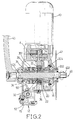
- an electrical drive in accordance with the present invention is provided for a bicycle which comprises a down tube 81, a pair of chain stays 80, a crank axle 40 rotatably disposed between the down tube 81 and the chain stays 80, two crank arms 43 each fixedly mounted around first and second end portions 402 and 404 of the crank axle 40, a chain wheel 42 rotatably disposed on the first end portion 402 of the crank axle 40, and a drive chain 46 meshing with the chain wheel 42 to move therewith.
- the electrical drive comprises a housing 12 mounted around the crank axle 40 and including a first half body 15 and a second half body 16 fixedly coupled with each other.
- a drive shaft 30 is rotatably mounted around the crank axle 40 and has a first end portion 302 located adjacent to the first end portion 402 of the crank axle 40 and a second end portion 304.
- the chain wheel 42 is adapted to be fixedly mounted around the first end portion 302 of the drive shaft 30.
- a single direction bearing 21 is fitted around the drive shaft 30 and a beveled gear 20 is mounted around the single direction bearing 21.
- a driving mechanism mounted in the housing 12 for driving the beveled gear 20.
- the driving mechanism includes a gear train (A) having a second beveled gear 14 meshing with the beveled gear 20, a motor 10 fixedly attached to the housing 12 for driving the gear train (A), and a battery box 101 fixedly mounted on the down tube 81 for supplying power to the motor 10.
- a container 102 is mounted around the down tube 81 for containing therein a central processing unit 100 (see Fig. 10).
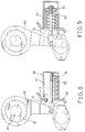
- a sensing race 33 is mounted on the second end portion 304 of the drive shaft 30 for rotating the drive shaft 30 along a single direction only, and a sensing interface 332 (see Fig. 5) is mounted along an outer wall of the sensing race 33.
- a linking member 32 is fixedly mounted between the crank axle 40 and the sensing race 33 for rotating the sensing race 33 by the crank axle 40.
- a velocity sensing unit 38 is mounted on the housing 12 and located adjacent to the sensing interface 332 for sensing a rotational velocity of the crank axle 40.
- the sensing race 33 includes an inner wall with a plurality of teeth 333 formed thereon.
- a ratchet base 22 is fixedly mounted on the second end portion 304 of the drive shaft 30 and has a plurality of recesses 222 defined along an outer wall thereof.
- a plurality of pawls 23 each have a first end pivotally received in one of the recesses 222 and a second end detachably meshing with each of the teeth 333.
- the sensing race 33 forms a meshing surface 331.
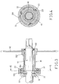
- a drive arm 34 is fixedly mounted on the second end portion 404 of the crank axle 40.
- a pivot axle 351 is fixedly mounted on an outer wall of the drive arm 34, and a drive gear 35 is rotatably mounted on the pivot axle 351 and meshes with the meshing surface 331.
- the drive arm 34 includes an inner wall defining a plurality of splines 341 therein, and the crank axle 40 forms a plurality of racks 41 each received in one of the splines 341.
- a sensing gear 36 is rotatably mounted on the second end portion 404 of the crank axle 40.
- a beveled surface 361 is formed on the sensing gear 36 and meshes with the drive gear 35.
- a sensing arm 50 is mounted on the sensing gear 36 to rotate therewith.
- the sensing arm 50 includes an inner wall forming a plurality of inner teeth 51, and the sensing gear 36 forms a plurality of drive teeth 362 each meshing with one of the inner teeth 51.
- a spring attachment 60 is fixedly mounted on the housing 12 and is connected with one distal end of the sensing arm 50.
- a torsion sensing unit 52 is mounted on the housing 12 and located adjacent to the spring attachment 60 for sensing a torsion exerted on the crank axle 40.
- the spring attachment 60 includes a casing 61 fixedly mounted on the housing 12, a linking rod 62 movably mounted in the casing 61 and having a first end pivotally attached to the distal end of the sensing arm 50, a plug 64 fixedly mounted on a second end of the linking rod 62, and a sensing spring 63 mounted around the linking rod 62 and urged between the plug 64 and an outer wall of the housing 12.
- a stop 53 is mounted on an inner wall of the housing 12 for limiting a further movement of the distal end of the sensing arm 50.
- crank axle 40 can be rotated by a rider exerting a torque on the two crank arms 43, thereby rotating the sensing race 33 which can rotate the drive shaft 30 along a normal direction only, thereby rotating the chain wheel 42 which meshes with the drive chain 46 so as to move the bicycle forwardly.
- the second beveled gear 14 of the gear train (A) can be driven by the motor 10 to rotate the beveled gear 20 which can rotate the drive shaft 30 along the normal direction only so as to rotate the chain wheel 50, thereby providing an assistance for moving the bicycle forwardly.
- the bicycle can be driven to travel forwardly by physical work of the rider and by electrical power synchronously.
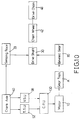
- the velocity sensing unit 38 located beside the sensing interface 332 can be used to detect the rotational velocity of the crank axle 40.
- the drive gear 35 can be used to rotate the sensing gear 36 which can rotate the sensing arm 50 which can move the linking rod 62, thereby compressing the sensing spring 63.
- the torsion sensing unit 52 located beside the sensing arm 50 can be used to detect the torsion exerted on the crank axle 40 by the rider depending on the compression of the sensing spring 63.
- the velocity sensing unit 38 can input signals indicating rotational velocities of the crank axle 40 and the torsion sensing unit 52 can input signals indicating torsions exerted by the rider on the crank axle 40 into the central processing unit 100 synchronously which can perform an analytic operation so as to determine power required for the motor 10 to drive the gear train (A) thereby precisely controlling the motor 10 to rotate the drive shaft 30, thereby providing a proper assistance for moving the bicycle.
- the power supplied by the motor 10 to drive the gear train (A) can be controlled, thereby optimizing the efficiency of the supplied electricity.
Priority Applications (1)
| Application Number | Priority Date | Filing Date | Title |
|---|---|---|---|
| EP97200547A EP0861770A1 (de) | 1997-02-26 | 1997-02-26 | Vorrichtung mit elektrischem Antrieb für ein Fahrrad |
Applications Claiming Priority (1)
| Application Number | Priority Date | Filing Date | Title |
|---|---|---|---|
| EP97200547A EP0861770A1 (de) | 1997-02-26 | 1997-02-26 | Vorrichtung mit elektrischem Antrieb für ein Fahrrad |
Publications (1)
| Publication Number | Publication Date |
|---|---|
| EP0861770A1 true EP0861770A1 (de) | 1998-09-02 |
Family
ID=8228052
Family Applications (1)
| Application Number | Title | Priority Date | Filing Date |
|---|---|---|---|
| EP97200547A Withdrawn EP0861770A1 (de) | 1997-02-26 | 1997-02-26 | Vorrichtung mit elektrischem Antrieb für ein Fahrrad |
Country Status (1)
| Country | Link |
|---|---|
| EP (1) | EP0861770A1 (de) |
Cited By (6)
| Publication number | Priority date | Publication date | Assignee | Title |
|---|---|---|---|---|
| WO2013067565A1 (de) * | 2011-11-10 | 2013-05-16 | Bionx Europe Gmbh | Muskelkraftbetriebenes fahrzeug mit hilfsmotor sowie getriebe und antriebseinheit hiefür |
| US11077914B2 (en) | 2017-10-13 | 2021-08-03 | Shimano Inc. | Bicycle drive unit |
| US11142283B2 (en) | 2017-10-13 | 2021-10-12 | Shimano Inc. | Bicycle drive unit |
| US11167817B2 (en) | 2017-10-13 | 2021-11-09 | Shimano Inc. | Bicycle drive unit |
| US11358677B2 (en) | 2017-10-13 | 2022-06-14 | Shimano Inc. | Bicycle component |
| US11433970B2 (en) | 2017-10-13 | 2022-09-06 | Shimano Inc. | Bicycle drive unit |
Citations (3)
| Publication number | Priority date | Publication date | Assignee | Title |
|---|---|---|---|---|
| EP0559231A1 (de) * | 1992-03-06 | 1993-09-08 | Yamaha Hatsudoki Kabushiki Kaisha | Fahrrad mit Elektromotor |
| EP0636537A1 (de) * | 1993-07-26 | 1995-02-01 | Yamaha Hatsudoki Kabushiki Kaisha | Antriebsübertragungssystem |
| EP0650887A2 (de) * | 1993-10-29 | 1995-05-03 | Yamaha Hatsudoki Kabushiki Kaisha | Pedalfahrzeug mit elektrischem Hilfsmotor |
-
1997
- 1997-02-26 EP EP97200547A patent/EP0861770A1/de not_active Withdrawn
Patent Citations (3)
| Publication number | Priority date | Publication date | Assignee | Title |
|---|---|---|---|---|
| EP0559231A1 (de) * | 1992-03-06 | 1993-09-08 | Yamaha Hatsudoki Kabushiki Kaisha | Fahrrad mit Elektromotor |
| EP0636537A1 (de) * | 1993-07-26 | 1995-02-01 | Yamaha Hatsudoki Kabushiki Kaisha | Antriebsübertragungssystem |
| EP0650887A2 (de) * | 1993-10-29 | 1995-05-03 | Yamaha Hatsudoki Kabushiki Kaisha | Pedalfahrzeug mit elektrischem Hilfsmotor |
Cited By (8)
| Publication number | Priority date | Publication date | Assignee | Title |
|---|---|---|---|---|
| WO2013067565A1 (de) * | 2011-11-10 | 2013-05-16 | Bionx Europe Gmbh | Muskelkraftbetriebenes fahrzeug mit hilfsmotor sowie getriebe und antriebseinheit hiefür |
| WO2013067566A1 (de) * | 2011-11-10 | 2013-05-16 | Bionx Europe Gmbh | Muskelkraftbetriebenes fahrzeug mit hilfsmotor sowie getriebe und antriebseinheit hiefür |
| US9315231B2 (en) | 2011-11-10 | 2016-04-19 | Bionx Europe Gmbh | Muscle-powered vehicle having an auxiliary motor, and transmission and drive unit therefor |
| US11077914B2 (en) | 2017-10-13 | 2021-08-03 | Shimano Inc. | Bicycle drive unit |
| US11142283B2 (en) | 2017-10-13 | 2021-10-12 | Shimano Inc. | Bicycle drive unit |
| US11167817B2 (en) | 2017-10-13 | 2021-11-09 | Shimano Inc. | Bicycle drive unit |
| US11358677B2 (en) | 2017-10-13 | 2022-06-14 | Shimano Inc. | Bicycle component |
| US11433970B2 (en) | 2017-10-13 | 2022-09-06 | Shimano Inc. | Bicycle drive unit |
Similar Documents
| Publication | Publication Date | Title |
|---|---|---|
| EP0820925A1 (de) | Elektrischer Antrieb für ein Fahrrad | |
| US5901807A (en) | Electrical drive for a bicycle | |
| EP0683093B1 (de) | Pedalkraftdetektor für Fahrrad mit Hilfsmotor | |
| EP2526010B1 (de) | Motor mit integriertem drehmomentsensor | |
| US5941333A (en) | Bicycle with a planetary-gear-train type transmission and an auxilliary electrical transmission | |
| US6516908B2 (en) | Transmission for an electric bicycle | |
| US5375676A (en) | Bicycle with electric motor | |
| WO2003057554A1 (fr) | Bicyclette assistee par electricite | |
| JP3547847B2 (ja) | アシストモータ付き自転車における踏力検出装置 | |
| EP1155953A3 (de) | Fahrrad-Antriebsvorrichtung | |
| EP0861770A1 (de) | Vorrichtung mit elektrischem Antrieb für ein Fahrrad | |
| EP1070660A1 (de) | Elektrischer Antrieb für ein Fahrrad | |
| EP3878726A1 (de) | Hilfsantriebsvorrichtung zur verwendung mit einem fahrrad | |
| EP0798203A1 (de) | Fahrrad mit elektrischem Hilfsmotor | |
| CN209351553U (zh) | 一种无阻力电动自行车 | |
| CN212172443U (zh) | 电动自行车的中轴传动机构 | |
| JP3042376U (ja) | 自転車用電気駆動装置 | |
| JP3066311U (ja) | 自転車用電気駆動装置 | |
| CN111391959A (zh) | 电动自行车的中轴传动机构 | |
| CN201099342Y (zh) | 电动滑板车的驱动装置 | |
| CN100493981C (zh) | 杠杆传动自行车 | |
| CN2245032Y (zh) | 正反向脚踏自行车 | |
| CN2151095Y (zh) | 电动自行车传动结构 | |
| CN216252426U (zh) | 差速电机、具有该差速电机的助力三轮车及助力四轮车 | |
| CN2387660Y (zh) | 电动自行车用电动机 |
Legal Events
| Date | Code | Title | Description |
|---|---|---|---|
| PUAI | Public reference made under article 153(3) epc to a published international application that has entered the european phase |
Free format text: ORIGINAL CODE: 0009012 |
|
| AK | Designated contracting states |
Kind code of ref document: A1 Designated state(s): AT BE CH DE DK ES FI FR GB GR IE IT LI LU MC NL PT SE |
|
| AX | Request for extension of the european patent |
Free format text: AL;LT;LV;RO;SI |
|
| AKX | Designation fees paid | ||
| RBV | Designated contracting states (corrected) | ||
| STAA | Information on the status of an ep patent application or granted ep patent |
Free format text: STATUS: THE APPLICATION IS DEEMED TO BE WITHDRAWN |
|
| 18D | Application deemed to be withdrawn |
Effective date: 19990303 |
|
| REG | Reference to a national code |
Ref country code: DE Ref legal event code: 8566 |