EP0634833B1 - Regelungssystem für einen Leistungswandler - Google Patents
Regelungssystem für einen Leistungswandler Download PDFInfo
- Publication number
- EP0634833B1 EP0634833B1 EP94305108A EP94305108A EP0634833B1 EP 0634833 B1 EP0634833 B1 EP 0634833B1 EP 94305108 A EP94305108 A EP 94305108A EP 94305108 A EP94305108 A EP 94305108A EP 0634833 B1 EP0634833 B1 EP 0634833B1
- Authority
- EP
- European Patent Office
- Prior art keywords
- value
- current
- detecting
- transformer
- magnetic flux
- Prior art date
- Legal status (The legal status is an assumption and is not a legal conclusion. Google has not performed a legal analysis and makes no representation as to the accuracy of the status listed.)
- Expired - Lifetime
Links
- 238000004804 winding Methods 0.000 claims description 59
- 230000004907 flux Effects 0.000 claims description 41
- 238000001514 detection method Methods 0.000 claims description 15
- 238000006243 chemical reaction Methods 0.000 claims description 7
- 230000005415 magnetization Effects 0.000 description 24
- 230000005284 excitation Effects 0.000 description 21
- 238000010586 diagram Methods 0.000 description 12
- 230000001052 transient effect Effects 0.000 description 7
- 239000003990 capacitor Substances 0.000 description 2
- 238000010304 firing Methods 0.000 description 2
- 230000001788 irregular Effects 0.000 description 2
- RYGMFSIKBFXOCR-UHFFFAOYSA-N Copper Chemical compound [Cu] RYGMFSIKBFXOCR-UHFFFAOYSA-N 0.000 description 1
- 230000005540 biological transmission Effects 0.000 description 1
- 238000010276 construction Methods 0.000 description 1
- 229910052802 copper Inorganic materials 0.000 description 1
- 239000010949 copper Substances 0.000 description 1
- 230000000694 effects Effects 0.000 description 1
- 238000005516 engineering process Methods 0.000 description 1
- 238000000034 method Methods 0.000 description 1
- 230000008054 signal transmission Effects 0.000 description 1
- 230000003068 static effect Effects 0.000 description 1
- 230000001629 suppression Effects 0.000 description 1
Images
Classifications
-
- G—PHYSICS
- G05—CONTROLLING; REGULATING
- G05F—SYSTEMS FOR REGULATING ELECTRIC OR MAGNETIC VARIABLES
- G05F1/00—Automatic systems in which deviations of an electric quantity from one or more predetermined values are detected at the output of the system and fed back to a device within the system to restore the detected quantity to its predetermined value or values, i.e. retroactive systems
- G05F1/10—Regulating voltage or current
- G05F1/12—Regulating voltage or current wherein the variable actually regulated by the final control device is AC
- G05F1/40—Regulating voltage or current wherein the variable actually regulated by the final control device is AC using discharge tubes or semiconductor devices as final control devices
- G05F1/44—Regulating voltage or current wherein the variable actually regulated by the final control device is AC using discharge tubes or semiconductor devices as final control devices semiconductor devices only
-
- H—ELECTRICITY
- H02—GENERATION; CONVERSION OR DISTRIBUTION OF ELECTRIC POWER
- H02M—APPARATUS FOR CONVERSION BETWEEN AC AND AC, BETWEEN AC AND DC, OR BETWEEN DC AND DC, AND FOR USE WITH MAINS OR SIMILAR POWER SUPPLY SYSTEMS; CONVERSION OF DC OR AC INPUT POWER INTO SURGE OUTPUT POWER; CONTROL OR REGULATION THEREOF
- H02M7/00—Conversion of AC power input into DC power output; Conversion of DC power input into AC power output
- H02M7/02—Conversion of AC power input into DC power output without possibility of reversal
- H02M7/04—Conversion of AC power input into DC power output without possibility of reversal by static converters
- H02M7/12—Conversion of AC power input into DC power output without possibility of reversal by static converters using discharge tubes with control electrode or semiconductor devices with control electrode
- H02M7/145—Conversion of AC power input into DC power output without possibility of reversal by static converters using discharge tubes with control electrode or semiconductor devices with control electrode using devices of a thyratron or thyristor type requiring extinguishing means
- H02M7/155—Conversion of AC power input into DC power output without possibility of reversal by static converters using discharge tubes with control electrode or semiconductor devices with control electrode using devices of a thyratron or thyristor type requiring extinguishing means using semiconductor devices only
- H02M7/162—Conversion of AC power input into DC power output without possibility of reversal by static converters using discharge tubes with control electrode or semiconductor devices with control electrode using devices of a thyratron or thyristor type requiring extinguishing means using semiconductor devices only in a bridge configuration
- H02M7/1623—Conversion of AC power input into DC power output without possibility of reversal by static converters using discharge tubes with control electrode or semiconductor devices with control electrode using devices of a thyratron or thyristor type requiring extinguishing means using semiconductor devices only in a bridge configuration with control circuit
Definitions
- This invention relates to a control system for a power converter, and more particularly relates to a control system for a power converter which is composed of self-turn-off devices such as, gate turn-off thyristors (hereafter, simply GTOs), and is connected to a power system or loads via transformers, which can prevent DC magnetization of the transformer.
- GTOs gate turn-off thyristors
- FIG. 7 shows a schematic diagram of a prior art control system for a power converter which is composed of GTOs (hereafter, called a self-commutated converter), and is used in a DC transmission system or a static var compensator and so on.
- GTOs hereafter, called a self-commutated converter
- PWM control circuit 10 determines the GTO firing pattern so that no DC component is contained in the output voltage of self-commutated converter 3. However, the actual output voltage takes a waveform which contains a DC component due to the variations in the characteristic of the GTO and the variations in the gate signal transmission time.
- the voltage of power system 1 is usually AC voltage.
- transient DC components may be included in the voltage of power system 1 such as when connecting the power capacitor or the transformer to power system 1.
- the DC magnetization due to the DC component generated by power system 1 cannot be suppressed, because no correction due to the DC component of the power system 1 side is made. Therefore, when a transient DC component is generated in the power system 1, transformer 2 will be magnetized asymmetrically and lead to an over-current.
- DE-A-4013171 discloses a device for removing DC components from the output of a multiphase DC/AC convertor comprising a DC source, a switching array, a filter and a transformer.
- the voltage of each phase on the secondary side of the transformer is detected and compared with a reference signal to generate signals to control the switching of the switching array.
- the switching signals of two of the three phases are also adjusted in dependence on the output from a respective DC component detector connected between that phase and the third phase.
- EP-A-0361389 discloses a further device for removing DC components from the output of a multiphase DC/AC converter, comprising a DC source, a DC/AC inverter and a transformer.
- the signal input to the primary side of the transformer is detected, and a DC component thereof is detected, and the DC/AC inverter . operation is controlled in accordance with the detected DC component.
- the outer system may comprise a power supply or a load, and the system according to the invention enables suppression of DC magnetization of the transformer even for the DC component generated by the power system side (the outer system).
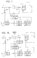
- Figure 1 is a schematic diagram of a control system for a power converter according to an embodiment of this invention.
- 5B is a current detector which detects the current on the primary winding side of transformer 2.
- 12 is a subtractor for finding the difference between the transformer secondary winding current detected by a current detector 5A and the transformer primary winding current detected by current detector 5B.
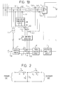
- Figure 2 shows a general equivalent circuit for transformer 2.
- X1 and X2 are leakage inductances of transformer 2; R1 and R2 are copper losses of transformer 2; X0 is an excitation inductance of transformer 2; and i1, i2 and i0 are respectively, a primary current, a secondary current and an excitation current flowing in transformer 2.
- the winding ratio of transformer 2 is taken as 1, excitation current i0 of transformer 2 is equal to the difference between primary current i1 and secondary current i2.
- Excitation current i0 almost corresponds to the magnetic flux of the core of transformer 2. Therefore, if a DC component included in excitation current i0 is detected, the value of DC magnetization can be estimated.
- the difference between the primary winding current and the secondary winding current of transformer 2 is computed by subtractor 12.
- a DC component in the current difference is detected by DC component detector 8.
- the output voltage instruction value from control circuit 7 is corrected by the DC component thus detected so that the DC magnetization is eliminated.
- the DC magnetization of transformer 2 can be suppressed.
- both DC magnetization due to the DC component included in the output of self-commutated converter 3 and the DC magnetization due to the transient DC component included in power system 1 can be corrected.
- Figure 1 shows the embodiment wherein the winding ratio of transformer 2 is taken as 1. This invention is not limited to this embodiment.
- Figure 1A shows a control system for a power converter according to another embodiment of this invention wherein the winding ratio of transformer 2 is 1 : n.
- 17 is a multiplier which multiplies the secondary winding current of transformer 2 detected by current detector 5A by n.
- the output of multiplier 17 is applied to subtractor 12, which finds the difference between the transformer primary current and the output of multiplier 17.
- the following control is executed the same as in the embodiment shown in Figure 1.
- the magnitude of the secondary winding current of transformer 2 is 1/n times that of the primary winding current of transformer 2.
- Multiplier 17 is provided for this purpose.
- a divider may be provided between current detector 5B and subtractor 12 which divides the primary winding current of transformer 2 detected by current detector 5B by n.
- FIG. 1B shows a control system for a power converter according to a further embodiment of this invention wherein power converter 3 is a three-phase power converter.
- transformer 2 is composed of a star-delta connection.
- 5A1, 5A2 and 5A3 are current detectors for detecting the currents on the secondary windings of transformer 2, respectively.
- 5B1, 5B2 and 5B3 are current detectors for detecting the currents on the primary windings of transformer 2, respectively.
- a star-delta conversion circuit 18 is provided for this purpose.
- the primary winding currents detected by current transformers 5B1, 5B2 and 5B3 are applied to star-delta conversion circuit 18.
- 121, 122 and 123 are subtractors for finding the differences between the three outputs of star-delta conversion circuit 18 and the secondary winding currents detected by current transformers 5A1, 5A2 and 5A3, respectively.
- DC component detector 8 detects the DC components contained in the outputs of subtractors 121, 122 and 123 and applies them to adders 91, 92 and 93, respectively.
- Adders 91, 92 and 93 add the three phase components of the output of control circuit 7 and the three outputs of DC component detector 8, respectively and apply the respective sums to PWM control circuit 10.
- a delta-star conversion circuit may be provided between current transformers 5A1, 5A2 and 5A3 in the secondary side and subtractors 121, 122 and 123.
- circuit elements such as multiplier 17 and star-delta conversion circuit 18, are well known to those skilled in the art. Accordingly, the detailed description of the circuit construction of these circuit elements may be omitted.
- both the DC magnetization due to the DC components included in the output of the power converter and the DC magnetization due to the transient DC component included in the outer system can be corrected by:
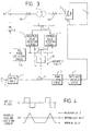
- the case is considered in which a current including DC component is flowing from power system 1 to self-commutated converter 3.
- the DC component of the primary winding current detected by current detector 5B is equal to that of the secondary winding current detected by current detector 5A in Figure 1, and no DC magnetization of transformer 2 occurs. Accordingly, the output of DC component detector 8 is zero, so that no correction to the instruction value outputted from control circuit 7 is executed.
- 19 is a phase detection circuit, such as a phase locked loop circuit, which outputs a signal at every fundamental period of power system 1.
- This signal is applied to a maximum value detection circuit 13 and a minimum value detection circuit 14.
- the current difference between the transformer primary current and secondary current computed by subtractor 12 is also applied to maximum value detection circuit 13 and minimum value detection circuit 14.
- Maximum value detection circuit 13 and minimum value detection circuit 14 detect the maximum and the minimum values of the current difference at every fundamental period of power system 1, respectively.
- 15 is an arithmetic circuit which computes the center value of the current difference at every fundamental period of power system 1 from the maximum and minimum values. The center value is applied to adder 9.
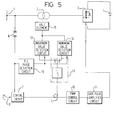
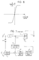
- FIG. 5 16 is a magnetic detector, such as a Hall element, for detecting the magnetic flux of the core of transformer 2.
- the output voltage instruction of control circuit 7 is corrected using the value of magnetic flux of the core of transformer 2, instead of the current difference between the transformer primary winding current and the transformer secondary winding current in Figure 3.
- the following control is executed the same as in the embodiment shown in Figure 3.
- the relationship between excitation current and magnetic flux in transformer 2 is non-linear.
- the excitation current only gradually increases until the core of transformer 2 reaches saturation. However, when the core reaches saturation, it increases rapidly. Therefore, in order to suppress DC magnetization by correcting before saturation is reached, the detection of a DC component of a small excitation current, or a small variation in excitation current. In order to detect such a small variation, the detection of the excitation current must be highly accurate.
- the magnitude of the excitation current is less than 10% of that of the rated current of a transformer. Therefore, when detecting the excitation current by the difference between the primary winding current and the secondary winding current, a current detector with an accuracy of 0.1% of the rated current is required in the case of detecting with an accuracy of 1% an excitation current the magnitude of which is 10% that of the rated current.
- both the DC magnetization due to the DC component included in the output of self-commutated converter 3 and the DC magnetization due to the transient DC component included in power system 1 can be effectively corrected.
- maximum value detection circuit 13 and minimum value detection circuit 14 detect the maximum and the minimum values from the inputted values at every fundamental period of power system 1. This invention is not limited to these embodiments. The maximum and the minimum values may be detected from the inputted values once for a plurality of fundamental periods of power system 1.
- a center value is computed in arithmetic circuit 15, and correction of the instruction value of control circuit 7 is executed by the center value.
- an appropriate value representing magnetic flux may be calculated from the magnetic flux or the exciting current in transformer 2 by a different method, and this value then may then be used for the correction of the instruction value from the control circuit, if DC magnetization of transformer 2 can be judged based on such a magnetic flux relating value.
- both the DC magnetization due to the DC component included in the power converter and the DC magnetization due to the transient DC component included in the outer system can be corrected by finding a value representing the magnetic flux of the core of the transformer, such as the difference between the DC primary winding current and the DC secondary winding current of the transformer, or a magnetic flux itself, and correcting the output voltage instruction value of the power converter based on the value representing magnetic flux.
Landscapes
- Engineering & Computer Science (AREA)
- Power Engineering (AREA)
- Physics & Mathematics (AREA)
- Electromagnetism (AREA)
- General Physics & Mathematics (AREA)
- Radar, Positioning & Navigation (AREA)
- Automation & Control Theory (AREA)
- Inverter Devices (AREA)
- Dc-Dc Converters (AREA)
- Control Of Electrical Variables (AREA)
- Supply And Distribution Of Alternating Current (AREA)
Claims (10)
- Regelsystem für einen Umrichter (3), der eine Anzahl Schalteinrichtungen enthält und über einem Transformator (2), der einen Kern aufweist, mit einem äußeren System (1) verbunden ist, wobei das Regelsystem umfaßt:eine Erzeugungsvorrichtung (7) für einen Ausgangsspannungs-Anweisungswert, die einen Anweisungswert für eine Ausgangsspannung des Umrichters (3) erzeugt;Korrekturvorrichtungen (5, 8, 9) zum Korrigieren des Anweisungswerts und zum Erzeugen eines korrigierten Anweisungswerts für die Ausgangsspannung des Umrichters (3); undSignalerzeugungsvorrichtungen (10, 11) zum Erzeugen eines Signals abhängig von dem korrigierten Anweisungswert, wobei das Signal an die Schalteinrichtungen des Umrichters (3) angelegt wird, um die Ausgangsspannung.des Umrichters (3) zu regeln, dadurch gekennzeichnet, daßdie Korrekturvorrichtung (5A, 5B, 8, 9, 12; 5A, 5B, 9, 12, 13, 14, 15; 9, 13, 14, 15, 16) einen korrigierten Anweisungswert erzeugt, und zwar abhängig von einem Wert, der den Gleichanteil des magnetischen Flußes im Kern des Transformators (2) darstellt.
- Regelsystem nach Anspruch 1, worin die Korrekturvorrichtung enthält:eine Erfassungsvorrichtung (16) für den magnetischen Fluß, die den magnetischen Fluß im Kern des Transformators (2) erfaßt;eine Maximalwert-Erfassungsvorrichtung (13), die so geschaltet ist, daß sie den magnetischen Fluß empfängt und innerhalb einer vorbestimmten Zeitspanne einen Maximalwert des magnetischen Flußes erfaßt;eine Minimalwert-Erfassungsvorrichtung (14), die so geschaltet ist, daß sie den magnetischen Fluß empfängt und innerhalb der vorbestimmten Zeitspanne einen Minimalwert des magnetischen Flußes erfaßt;eine Mittelwert-Berechnungsvorrichtung (15) zum Berechnen eines Mittelwerts aus dem Maximalwert und dem Minimalwert innerhalb der vorbestimmten Zeitspanne, wobei der Mittelwert der Wert ist, der den Gleichanteil des magnetischen Flußes darstellt; undeine Erzeugungsvorrichtung (9) für korrigierte Anweisungswerte, die so geschaltet ist, daß sie den Anweisungswert und den Wert empfängt, der den Gleichanteil des magnetischen Flußes darstellt, und den korrigierten Anweisungswert für die Ausgangsspannung des Umrichters (3) erzeugt.
- Regelsystem für einen Umrichter nach Anspruch 2,
wobei die Korrekturvorrichtung zudem einen Phasendetektor (19) zum Erfassen einer Grundschwingungsdauer des äußeren Systems (1) enthält,
und für die Korrekturvorrichtung gilt:die Erzeugungsvorrichtung (16) für den magnetischen Fluß enthält ein Hallelement, das in dem Transformator (2) bereitgestellt ist und den magnetischen Fluß im Kern des Transformators (2) erfaßt;die Maximalwert-Erfassungsvorrichtung (13) enthält eine Maximalwert-Erfassungsschaltung, die so geschaltet ist, daß sie den magnetischen Fluß und die Grundschwingungsdauer als die vorbestimmte Zeitspanne empfängt und den Maximalwert des magnetischen Flußes innerhalb der Grundschwingungsdauer erfaßt;die Minimalwert-Erfassungsvorrichtung (14) enthält eine Minimalwert-Erfassungsschaltung, die so geschaltet ist, daß sie den magnetischen Fluß und die Grundschwingungsdauer als die vorbestimmte Zeitspanne empfängt und den Minimalwert des magnetischen Flußes innerhalb der Grundschwingungsdauer erfaßt;die Mittelwert-Berechnungsvorrichtung (15) enthält eine Arithmetikschaltung, die während der Grundschwingungsdauer aus dem Maximalwert und dem Minimalwert den Mittelwert berechnet, wobei der Mittelwert der Wert ist, der den Gleichanteil des magnetischen Flußes darstellt; unddie Erzeugungsvorrichtung (9) für korrigierte Anweisungswerte enthält einen Addierer, der den Anweisungswert und den Wert addiert, der den Gleichanteil des magnetischen Flußes darstellt, um den korrigierten Anweisungswert zu erzeugen. - Regelsystem nach Anspruch 1, worin die Korrekturvorrichtung enthält:eine Stromdifferenz-Erfassungsvorrichtung (5A, 5B, 12) zum Erfassen einer Stromdifferenz zwischen einem Primärwicklungsstrom (i1) und einem Sekundärwicklungsstrom (i2) des Transformators (2);eine Maximalwert-Erfassungsvorrichtung (13), die so geschaltet ist, daß sie die Stromdifferenz empfängt und einen Maximalwert der Stromdifferenz innerhalb einer vorbestimmten Zeitspanne erfaßt;eine Minimalwert-Erfassungsvorrichtung (14) die so geschaltet ist, daß sie die Stromdifferenz empfängt und einen Minimalwert der Stromdifferenz innerhalb der vorbestimmten Zeitspanne erfaßt;eine Mittelwert-Berechnungsvorrichtung (15) zum Berechnen eines Mittelwerts aus dem Maximalwert und dem Minimalwert innerhalb der vorbestimmten Zeitspanne, wobei der Mittelwert der Wert ist, der den Gleichanteil des magnetischen Flußes darstellt; undeine Erzeugungsvorrichtung (9) für korrigierte Anweisungswerte, die so geschaltet ist, daß sie den Anweisungswert und den Wert empfängt, der den Gleichanteil des magnetischen Flußes darstellt und den korrigierten Anweisungswert für die Ausgangsspannung des Umrichters erzeugt.
- Regelsystem für einen Umrichter nach Anspruch 4,
wobei die Korrekturvorrichtung zudem einen Phasendetektor (19) zum Erfassen einer Grundschwingungsdauer des äußeren Systems (1) enthält,
und für die Korrekturvorrichtung gilt:die Stromdifferenz-Erfassungsvorrichtung umfaßteinen Primärstromdetektor (5B) zum Erfassen des Primärwicklungsstroms des Transformators,einen Sekundärstromdetektor (5A) zum Erfassen des Sekundärwicklungsstroms des Transformators,einen Subtrahierer (12) zum Berechnen der Differenz zwischen dem Primärwicklungsstrom und dem Sekundärwicklungsstrom;die Maximalwert-Erfassungsvorrichtung (13) enthält eine Maximalwert-Erfassungsschaltung, die so geschaltet ist, daß sie die Stromdifferenz und die Grundschwingungsdauer als die vorbestimmte Zeitspanne empfängt und den Maximalwert der Stromdifferenz während der Grundschwingungsdauer erfaßt;die Minimalwert-Erfassungsvorrichtung (14) enthält eine Minimalwert-Erfassungsschaltung, die so geschaltet ist, daß sie die Stromdifferenz und die Grundschwingungsdauer als die vorbestimmte Zeitspanne empfängt und den Minimalwert der Stromdifferenz während der Grundschwingungsdauer erfaßt;die Mittelwert-Berechnungsvorrichtung (15) enthält eine Arithmetikschaltung, die während der Grundschwingungsdauer aus dem Maximalwert und dem Minimalwert den Mittelwert berechnet, wobei der Mittelwert der Wert ist, der den Gleichanteil des magnetischen Flußes darstellt; unddie Erzeugungsvorrichtung für korrigierte Anweisungswerte enthält einen Addierer (9), der den Anweisungswert und den Wert addiert, der den Gleichanteil des magnetischen Flußes darstellt, um den korrigierten Anweisungswert zu erzeugen. - Regelsystem nach Anspruch 1, worin die Korrekturvorrichtung enthält:Stromdifferenz-Erfassungsvorrichtungen (5A, 5B) zum Erfassen einer Stromdifferenz zwischen einem Primärwicklungsstrom und einem Sekundärwicklungsstrom des Transformators;eine Gleichanteil-Erfassungsvorrichtung (8) zum Erfassen des Gleichanteils, der in der Stromdifferenz enthalten ist, wobei der Gleichanteil der Wert ist, der den Gleichanteil des magnetischen Flußes darstellt; undeine Erzeugungsvorrichtung (9) für korrigierte Anweisungswerte, die so geschaltet ist, daß sie den Anweisungswert und den Wert empfängt, der den Gleichanteil des magnetischen Flußes darstellt, und den korrigierten Anweisungswert für die Ausgangsspannung des Umrichters erzeugt.
- Regelsystem für einen Umrichter nach Anspruch 6, worin die Stromdifferenz-Erfassungsvorrichtung enthält:einen Primärstromdetektor (5B) zum Erfassen des Primärwicklungsstroms des Transformators,einen Sekundärstromdetektor (5A) zum Erfassen des Sekundärwicklungsstroms des Transformators,einen Subtrahierer (12) zum Berechnen der Stromdifferenz zwischen dem Primärwicklungsstrom und dem Sekundärwicklungsstrom.
- Regelsystem für einen Umrichter nach Anspruch 6,
wobei das Windungszahlenverhältnis des Transformators den Wert 1 : n hat und
die Stromdifferenz-Erfassungsvorrichtung enthält:einen Primärstromdetektor (5B) zum Erfassen des Primärwicklungsstroms des Transformators,einen Sekundärstromdetektor (5A) zum Erfassen des Sekundärwicklungsstroms des Transformators,einen Multiplizierer (17), der den Sekundärwicklungsstrom mit n multipliziert und einen multiplizierten Sekundärwicklungsstrom erzeugt; undeinen Subtrahierer (12) zum Berechnen einer Differenz zwischen dem Primärwicklungsstrom und dem multiplizierten Sekundärwicklungsstrom und zum Ausgeben der Differenz als Stromdifferenz. - Regelsystem für einen Umrichter nach Anspruch 6,wobei der Umrichter (3) ein dreiphasiger Umrichter ist und der Transformator (2) in Stern-Dreieck-Schaltung aufgebaut ist,und die Stromdifferenz-Erfassungsvorrichtung enthält:Primärstrom-Erfassungsvorrichtungen (5B1, 5B2, 5B3) zum Erfassen des Primärwicklungsstroms des Transformators;Sekundärstrom-Erfassungsvorrichtungen (5A1, 5A2, 5A3) zum Erfassen des Sekundärwicklungsstroms des Transformators;eine Stern-Dreieck-Umsetzvorrichtung (18) zum Umsetzen des Primärwicklungsstroms in einen umgesetzten Primärwicklungsstrom; undSubtrahiervorrichtungen (121, 122, 123) zum Berechnen einer Differenz zwischen dem umgesetzten Primärwicklungsstrom und dem Sekundärwicklungsstrom, wobei die Differenz die Stromdifferenz ist.
- Regelsystem für einen Umrichter nach irgendeinem der vorhergehenden Ansprüche, wobei das äußere System entweder ein Netz oder eine Last enthält.
Applications Claiming Priority (2)
| Application Number | Priority Date | Filing Date | Title |
|---|---|---|---|
| JP172766/93 | 1993-07-13 | ||
| JP5172766A JPH0728534A (ja) | 1993-07-13 | 1993-07-13 | 電力変換装置の制御装置 |
Publications (2)
| Publication Number | Publication Date |
|---|---|
| EP0634833A1 EP0634833A1 (de) | 1995-01-18 |
| EP0634833B1 true EP0634833B1 (de) | 1998-10-28 |
Family
ID=15947946
Family Applications (1)
| Application Number | Title | Priority Date | Filing Date |
|---|---|---|---|
| EP94305108A Expired - Lifetime EP0634833B1 (de) | 1993-07-13 | 1994-07-13 | Regelungssystem für einen Leistungswandler |
Country Status (5)
| Country | Link |
|---|---|
| US (1) | US5450310A (de) |
| EP (1) | EP0634833B1 (de) |
| JP (1) | JPH0728534A (de) |
| CA (1) | CA2127834C (de) |
| DE (1) | DE69414197T2 (de) |
Families Citing this family (11)
| Publication number | Priority date | Publication date | Assignee | Title |
|---|---|---|---|---|
| JP3167936B2 (ja) * | 1996-08-08 | 2001-05-21 | 三菱電機株式会社 | 電力変換装置 |
| DE19648696A1 (de) * | 1996-11-25 | 1998-05-28 | Asea Brown Boveri | Verfahren und Vorrichtung zur Ausregelung des DC-Offsets eines Umrichters |
| DE19734272C1 (de) * | 1997-08-07 | 1999-01-07 | Siemens Ag | Verfahren und Vorrichtung zur Ausregelung von Verzerrungen im Magnetisierungsstrom eines Transformators, der mit einem selbstgeführten Stromrichter mit abschaltbarem Leistungshalbleiterschalter verknüpft ist |
| JP4449882B2 (ja) * | 2005-10-14 | 2010-04-14 | 株式会社デンソー | 車両用発電制御装置 |
| DE602007014267D1 (de) * | 2007-08-31 | 2011-06-09 | Abb Technology Ag | Symmetrischen gleichstrom-vorstroms in einem mit einem hochspannungsumrichter verbundenen leistungstransformator |
| JP5646237B2 (ja) * | 2010-07-26 | 2014-12-24 | 株式会社東芝 | 変圧器の残留磁束推定方法及び残留磁束推定装置 |
| US9014336B2 (en) | 2010-12-15 | 2015-04-21 | Koninklijke Philips N.V. | Power supply unit for an X-ray tube |
| DE102012218710B4 (de) | 2012-10-15 | 2016-08-04 | Continental Automotive Gmbh | Vorrichtung zum Vergleichen des Stromes durch die Hauptinduktivität eines Transformators mit einem Vergleichswert und Zweipunktregler mit einer solchen Vorrichtung |
| JP2014150598A (ja) * | 2013-01-31 | 2014-08-21 | Hitachi Ltd | 電力変換装置及び変圧器の偏磁判定方法 |
| WO2019167271A1 (ja) * | 2018-03-02 | 2019-09-06 | 三菱電機株式会社 | 電力変換装置 |
| JP6906464B2 (ja) * | 2018-03-15 | 2021-07-21 | 株式会社東芝 | 電力変換装置の制御装置および制御方法 |
Family Cites Families (13)
| Publication number | Priority date | Publication date | Assignee | Title |
|---|---|---|---|---|
| US3667027A (en) * | 1971-03-30 | 1972-05-30 | Bell Electronic Corp | Inverter circuit with stabilized frequency under all load conditions |
| US4173779A (en) * | 1978-12-08 | 1979-11-06 | Westinghouse Electric Corp. | Single-pole commutation circuit |
| US4611267A (en) * | 1985-02-25 | 1986-09-09 | General Electric Company | Snubber arrangements with energy recovery for power converters using self-extinguishing devices |
| JPH0724463B2 (ja) * | 1986-03-07 | 1995-03-15 | 株式会社東芝 | 電力変換装置 |
| JPH01152969A (ja) * | 1987-12-07 | 1989-06-15 | Toshiba Corp | インバータ制御装置 |
| JP2783555B2 (ja) * | 1988-09-26 | 1998-08-06 | 株式会社東芝 | 電力変換装置 |
| JPH0777516B2 (ja) * | 1989-04-27 | 1995-08-16 | 三菱電機株式会社 | 多相インバータの出力直流分防止装置 |
| JPH02307374A (ja) * | 1989-05-22 | 1990-12-20 | Hitachi Ltd | 電力変換装置 |
| JPH03139175A (ja) * | 1989-10-24 | 1991-06-13 | Toshiba Corp | Pwm制御電力変換装置 |
| JPH0728538B2 (ja) * | 1990-04-18 | 1995-03-29 | 株式会社東芝 | Pwmインバータの制御装置 |
| JP2774685B2 (ja) * | 1990-09-12 | 1998-07-09 | 株式会社東芝 | 3相変圧器の直流偏磁抑制制御を備えたインバータ制御装置 |
| JP3219783B2 (ja) * | 1991-04-23 | 2001-10-15 | 株式会社東芝 | 電力変換装置 |
| JPH05236761A (ja) * | 1992-02-20 | 1993-09-10 | Toshiba Corp | 変圧器の直流偏磁防止装置 |
-
1993
- 1993-07-13 JP JP5172766A patent/JPH0728534A/ja active Pending
-
1994
- 1994-07-12 CA CA002127834A patent/CA2127834C/en not_active Expired - Fee Related
- 1994-07-13 EP EP94305108A patent/EP0634833B1/de not_active Expired - Lifetime
- 1994-07-13 DE DE69414197T patent/DE69414197T2/de not_active Expired - Fee Related
- 1994-07-13 US US08/274,454 patent/US5450310A/en not_active Expired - Lifetime
Also Published As
| Publication number | Publication date |
|---|---|
| CA2127834C (en) | 1997-06-03 |
| EP0634833A1 (de) | 1995-01-18 |
| JPH0728534A (ja) | 1995-01-31 |
| US5450310A (en) | 1995-09-12 |
| DE69414197T2 (de) | 1999-03-18 |
| DE69414197D1 (de) | 1998-12-03 |
| CA2127834A1 (en) | 1995-01-14 |
Similar Documents
| Publication | Publication Date | Title |
|---|---|---|
| US5852554A (en) | Power inverter having three or more parallel driven PWM-type power inverting units | |
| US5177428A (en) | Inverter control device capable of supressing dc magnetization in three-phase transformer | |
| EP0634833B1 (de) | Regelungssystem für einen Leistungswandler | |
| US5621633A (en) | Apparatus for controlling converter having self-arc-extinction elements | |
| JP2527911B2 (ja) | Pwmコンバ―タ | |
| JP6443652B2 (ja) | 電力変換装置 | |
| JP5955644B2 (ja) | インバータゲート制御回路および当該インバータゲート制御回路を備えたインバータ電源装置 | |
| JPS6399770A (ja) | 循環電流形サイクロコンバ−タの制御方法 | |
| JP3247252B2 (ja) | 電力変換装置の制御装置 | |
| JP3256814B2 (ja) | 多相電力変換器の制御装置 | |
| JP3501548B2 (ja) | 高周波変圧器の偏磁防止回路 | |
| JP2006136107A (ja) | 半導体電力変換装置、およびその偏磁制御方法 | |
| JPH0728538B2 (ja) | Pwmインバータの制御装置 | |
| JPH11289775A (ja) | 電力変換装置 | |
| JP4607617B2 (ja) | 電力変換装置の制御装置 | |
| JPH10229682A (ja) | 電力変換装置の制御方法 | |
| JP2025033404A (ja) | 電力変換装置 | |
| JP3274274B2 (ja) | 偏磁抑制制御回路 | |
| JP2509890B2 (ja) | 交直変換装置のパルス幅変調制御方式 | |
| JPH10145973A (ja) | 電力用アクティブフィルタの制御方法 | |
| JP2835165B2 (ja) | 3相変圧器の直流偏磁抑制制御を備えたインバータ制御装置 | |
| JP2534035Y2 (ja) | インバータ用変圧器の偏磁防止回路 | |
| JP3395310B2 (ja) | 半導体電力変換装置 | |
| JP2658620B2 (ja) | 電力変換器の制御回路 | |
| JPH09215345A (ja) | 無停電電源装置 |
Legal Events
| Date | Code | Title | Description |
|---|---|---|---|
| PUAI | Public reference made under article 153(3) epc to a published international application that has entered the european phase |
Free format text: ORIGINAL CODE: 0009012 |
|
| 17P | Request for examination filed |
Effective date: 19940804 |
|
| AK | Designated contracting states |
Kind code of ref document: A1 Designated state(s): DE FR GB SE |
|
| 17Q | First examination report despatched |
Effective date: 19961204 |
|
| GRAG | Despatch of communication of intention to grant |
Free format text: ORIGINAL CODE: EPIDOS AGRA |
|
| GRAG | Despatch of communication of intention to grant |
Free format text: ORIGINAL CODE: EPIDOS AGRA |
|
| GRAH | Despatch of communication of intention to grant a patent |
Free format text: ORIGINAL CODE: EPIDOS IGRA |
|
| GRAH | Despatch of communication of intention to grant a patent |
Free format text: ORIGINAL CODE: EPIDOS IGRA |
|
| GRAA | (expected) grant |
Free format text: ORIGINAL CODE: 0009210 |
|
| AK | Designated contracting states |
Kind code of ref document: B1 Designated state(s): DE FR GB SE |
|
| PG25 | Lapsed in a contracting state [announced via postgrant information from national office to epo] |
Ref country code: FR Free format text: LAPSE BECAUSE OF FAILURE TO SUBMIT A TRANSLATION OF THE DESCRIPTION OR TO PAY THE FEE WITHIN THE PRESCRIBED TIME-LIMIT Effective date: 19981028 |
|
| REF | Corresponds to: |
Ref document number: 69414197 Country of ref document: DE Date of ref document: 19981203 |
|
| RIN2 | Information on inventor provided after grant (corrected) |
Free format text: KAWAKMI, NORIKO, C/O INTELLECTUAL PROPERTY DIV. |
|
| EN | Fr: translation not filed | ||
| RIN2 | Information on inventor provided after grant (corrected) |
Free format text: KAWAKAMI NORIKO, C/O INTELLECTUAL PROPERTY DIV. |
|
| PLBE | No opposition filed within time limit |
Free format text: ORIGINAL CODE: 0009261 |
|
| STAA | Information on the status of an ep patent application or granted ep patent |
Free format text: STATUS: NO OPPOSITION FILED WITHIN TIME LIMIT |
|
| 26N | No opposition filed | ||
| PGFP | Annual fee paid to national office [announced via postgrant information from national office to epo] |
Ref country code: GB Payment date: 20000713 Year of fee payment: 7 |
|
| PG25 | Lapsed in a contracting state [announced via postgrant information from national office to epo] |
Ref country code: GB Free format text: LAPSE BECAUSE OF NON-PAYMENT OF DUE FEES Effective date: 20010713 |
|
| GBPC | Gb: european patent ceased through non-payment of renewal fee |
Effective date: 20010713 |
|
| PGFP | Annual fee paid to national office [announced via postgrant information from national office to epo] |
Ref country code: DE Payment date: 20030724 Year of fee payment: 10 |
|
| PG25 | Lapsed in a contracting state [announced via postgrant information from national office to epo] |
Ref country code: DE Free format text: LAPSE BECAUSE OF NON-PAYMENT OF DUE FEES Effective date: 20050201 |
|
| PGFP | Annual fee paid to national office [announced via postgrant information from national office to epo] |
Ref country code: SE Payment date: 20130711 Year of fee payment: 20 |
|
| REG | Reference to a national code |
Ref country code: SE Ref legal event code: EUG |