EP0629788B1 - Linearführungseinrichtung mit Laufbahnschmierelementen - Google Patents
Linearführungseinrichtung mit Laufbahnschmierelementen Download PDFInfo
- Publication number
- EP0629788B1 EP0629788B1 EP94105806A EP94105806A EP0629788B1 EP 0629788 B1 EP0629788 B1 EP 0629788B1 EP 94105806 A EP94105806 A EP 94105806A EP 94105806 A EP94105806 A EP 94105806A EP 0629788 B1 EP0629788 B1 EP 0629788B1
- Authority
- EP
- European Patent Office
- Prior art keywords
- rail
- guide
- carrier
- guide rail
- treating
- Prior art date
- Legal status (The legal status is an assumption and is not a legal conclusion. Google has not performed a legal analysis and makes no representation as to the accuracy of the status listed.)
- Expired - Lifetime
Links
- 230000001050 lubricating effect Effects 0.000 title claims abstract description 112
- 239000000314 lubricant Substances 0.000 claims abstract description 119
- 238000007790 scraping Methods 0.000 claims description 42
- 238000005096 rolling process Methods 0.000 claims description 21
- 239000004033 plastic Substances 0.000 claims description 15
- 229920003023 plastic Polymers 0.000 claims description 15
- 238000007789 sealing Methods 0.000 claims description 13
- 239000000463 material Substances 0.000 claims description 12
- 238000003466 welding Methods 0.000 claims description 9
- 230000002093 peripheral effect Effects 0.000 claims description 8
- 239000002184 metal Substances 0.000 claims description 7
- 229910052751 metal Inorganic materials 0.000 claims description 7
- 230000009471 action Effects 0.000 claims description 6
- 230000035515 penetration Effects 0.000 claims description 6
- 238000010276 construction Methods 0.000 claims description 4
- 239000013536 elastomeric material Substances 0.000 claims description 4
- 210000002445 nipple Anatomy 0.000 claims description 4
- 239000002245 particle Substances 0.000 claims description 4
- 238000004026 adhesive bonding Methods 0.000 claims description 3
- 230000004323 axial length Effects 0.000 claims description 3
- 238000002347 injection Methods 0.000 claims description 3
- 239000007924 injection Substances 0.000 claims description 3
- 238000003780 insertion Methods 0.000 claims description 3
- 230000037431 insertion Effects 0.000 claims description 3
- 229910001369 Brass Inorganic materials 0.000 claims description 2
- 229910000831 Steel Inorganic materials 0.000 claims description 2
- 239000010951 brass Substances 0.000 claims description 2
- 230000000295 complement effect Effects 0.000 claims description 2
- 239000004020 conductor Substances 0.000 claims description 2
- 230000005489 elastic deformation Effects 0.000 claims description 2
- 239000012535 impurity Substances 0.000 claims description 2
- 239000010959 steel Substances 0.000 claims description 2
- 230000003449 preventive effect Effects 0.000 claims 4
- 230000000284 resting effect Effects 0.000 claims 2
- 230000013011 mating Effects 0.000 claims 1
- 238000000465 moulding Methods 0.000 claims 1
- 238000000926 separation method Methods 0.000 claims 1
- 238000005461 lubrication Methods 0.000 description 34
- 238000013461 design Methods 0.000 description 12
- 238000004519 manufacturing process Methods 0.000 description 12
- 238000003860 storage Methods 0.000 description 10
- 230000006835 compression Effects 0.000 description 8
- 238000007906 compression Methods 0.000 description 8
- 239000000945 filler Substances 0.000 description 4
- 238000000034 method Methods 0.000 description 4
- 239000000243 solution Substances 0.000 description 4
- 239000000356 contaminant Substances 0.000 description 3
- 230000000694 effects Effects 0.000 description 3
- 229920001971 elastomer Polymers 0.000 description 3
- 239000000806 elastomer Substances 0.000 description 3
- 230000036316 preload Effects 0.000 description 3
- 230000008569 process Effects 0.000 description 3
- 239000011324 bead Substances 0.000 description 2
- 238000011109 contamination Methods 0.000 description 2
- 238000005520 cutting process Methods 0.000 description 2
- 238000011161 development Methods 0.000 description 2
- 230000018109 developmental process Effects 0.000 description 2
- 238000004512 die casting Methods 0.000 description 2
- 238000005516 engineering process Methods 0.000 description 2
- 239000004519 grease Substances 0.000 description 2
- 238000001746 injection moulding Methods 0.000 description 2
- 241000196324 Embryophyta Species 0.000 description 1
- 244000043261 Hevea brasiliensis Species 0.000 description 1
- HCHKCACWOHOZIP-UHFFFAOYSA-N Zinc Chemical compound [Zn] HCHKCACWOHOZIP-UHFFFAOYSA-N 0.000 description 1
- 230000001154 acute effect Effects 0.000 description 1
- 230000006978 adaptation Effects 0.000 description 1
- 239000000853 adhesive Substances 0.000 description 1
- 230000001070 adhesive effect Effects 0.000 description 1
- 238000013459 approach Methods 0.000 description 1
- 230000008901 benefit Effects 0.000 description 1
- 230000002146 bilateral effect Effects 0.000 description 1
- 239000000969 carrier Substances 0.000 description 1
- 238000005266 casting Methods 0.000 description 1
- 230000008859 change Effects 0.000 description 1
- 239000003795 chemical substances by application Substances 0.000 description 1
- 230000007423 decrease Effects 0.000 description 1
- 238000009826 distribution Methods 0.000 description 1
- 230000003028 elevating effect Effects 0.000 description 1
- 230000002349 favourable effect Effects 0.000 description 1
- 239000010687 lubricating oil Substances 0.000 description 1
- 239000007769 metal material Substances 0.000 description 1
- 239000000203 mixture Substances 0.000 description 1
- 238000012986 modification Methods 0.000 description 1
- 230000004048 modification Effects 0.000 description 1
- 229920003052 natural elastomer Polymers 0.000 description 1
- 229920001194 natural rubber Polymers 0.000 description 1
- 239000002861 polymer material Substances 0.000 description 1
- 238000003825 pressing Methods 0.000 description 1
- 239000000565 sealant Substances 0.000 description 1
- 238000007493 shaping process Methods 0.000 description 1
- 230000006641 stabilisation Effects 0.000 description 1
- 238000011105 stabilization Methods 0.000 description 1
- 239000013589 supplement Substances 0.000 description 1
- 238000012360 testing method Methods 0.000 description 1
- 210000002105 tongue Anatomy 0.000 description 1
- 238000012549 training Methods 0.000 description 1
- 230000007704 transition Effects 0.000 description 1
- 239000011701 zinc Substances 0.000 description 1
- 229910052725 zinc Inorganic materials 0.000 description 1
Images




Classifications
-
- F—MECHANICAL ENGINEERING; LIGHTING; HEATING; WEAPONS; BLASTING
- F16—ENGINEERING ELEMENTS AND UNITS; GENERAL MEASURES FOR PRODUCING AND MAINTAINING EFFECTIVE FUNCTIONING OF MACHINES OR INSTALLATIONS; THERMAL INSULATION IN GENERAL
- F16C—SHAFTS; FLEXIBLE SHAFTS; ELEMENTS OR CRANKSHAFT MECHANISMS; ROTARY BODIES OTHER THAN GEARING ELEMENTS; BEARINGS
- F16C29/00—Bearings for parts moving only linearly
- F16C29/04—Ball or roller bearings
- F16C29/06—Ball or roller bearings in which the rolling bodies circulate partly without carrying load
- F16C29/0633—Ball or roller bearings in which the rolling bodies circulate partly without carrying load with a bearing body defining a U-shaped carriage, i.e. surrounding a guide rail or track on three sides
- F16C29/0635—Ball or roller bearings in which the rolling bodies circulate partly without carrying load with a bearing body defining a U-shaped carriage, i.e. surrounding a guide rail or track on three sides whereby the return paths are provided as bores in a main body of the U-shaped carriage, e.g. the main body of the U-shaped carriage is a single part with end caps provided at each end
- F16C29/065—Ball or roller bearings in which the rolling bodies circulate partly without carrying load with a bearing body defining a U-shaped carriage, i.e. surrounding a guide rail or track on three sides whereby the return paths are provided as bores in a main body of the U-shaped carriage, e.g. the main body of the U-shaped carriage is a single part with end caps provided at each end with rollers
-
- B—PERFORMING OPERATIONS; TRANSPORTING
- B23—MACHINE TOOLS; METAL-WORKING NOT OTHERWISE PROVIDED FOR
- B23Q—DETAILS, COMPONENTS, OR ACCESSORIES FOR MACHINE TOOLS, e.g. ARRANGEMENTS FOR COPYING OR CONTROLLING; MACHINE TOOLS IN GENERAL CHARACTERISED BY THE CONSTRUCTION OF PARTICULAR DETAILS OR COMPONENTS; COMBINATIONS OR ASSOCIATIONS OF METAL-WORKING MACHINES, NOT DIRECTED TO A PARTICULAR RESULT
- B23Q1/00—Members which are comprised in the general build-up of a form of machine, particularly relatively large fixed members
- B23Q1/25—Movable or adjustable work or tool supports
- B23Q1/26—Movable or adjustable work or tool supports characterised by constructional features relating to the co-operation of relatively movable members; Means for preventing relative movement of such members
-
- F—MECHANICAL ENGINEERING; LIGHTING; HEATING; WEAPONS; BLASTING
- F16—ENGINEERING ELEMENTS AND UNITS; GENERAL MEASURES FOR PRODUCING AND MAINTAINING EFFECTIVE FUNCTIONING OF MACHINES OR INSTALLATIONS; THERMAL INSULATION IN GENERAL
- F16C—SHAFTS; FLEXIBLE SHAFTS; ELEMENTS OR CRANKSHAFT MECHANISMS; ROTARY BODIES OTHER THAN GEARING ELEMENTS; BEARINGS
- F16C29/00—Bearings for parts moving only linearly
- F16C29/08—Arrangements for covering or protecting the ways
- F16C29/084—Arrangements for covering or protecting the ways fixed to the carriage or bearing body movable along the guide rail or track
- F16C29/086—Seals being essentially U-shaped, e.g. for a U-shaped carriage
-
- F—MECHANICAL ENGINEERING; LIGHTING; HEATING; WEAPONS; BLASTING
- F16—ENGINEERING ELEMENTS AND UNITS; GENERAL MEASURES FOR PRODUCING AND MAINTAINING EFFECTIVE FUNCTIONING OF MACHINES OR INSTALLATIONS; THERMAL INSULATION IN GENERAL
- F16C—SHAFTS; FLEXIBLE SHAFTS; ELEMENTS OR CRANKSHAFT MECHANISMS; ROTARY BODIES OTHER THAN GEARING ELEMENTS; BEARINGS
- F16C33/00—Parts of bearings; Special methods for making bearings or parts thereof
- F16C33/30—Parts of ball or roller bearings
- F16C33/66—Special parts or details in view of lubrication
- F16C33/6637—Special parts or details in view of lubrication with liquid lubricant
- F16C33/6659—Details of supply of the liquid to the bearing, e.g. passages or nozzles
-
- F—MECHANICAL ENGINEERING; LIGHTING; HEATING; WEAPONS; BLASTING
- F16—ENGINEERING ELEMENTS AND UNITS; GENERAL MEASURES FOR PRODUCING AND MAINTAINING EFFECTIVE FUNCTIONING OF MACHINES OR INSTALLATIONS; THERMAL INSULATION IN GENERAL
- F16N—LUBRICATING
- F16N7/00—Arrangements for supplying oil or unspecified lubricant from a stationary reservoir or the equivalent in or on the machine or member to be lubricated
- F16N7/12—Arrangements for supplying oil or unspecified lubricant from a stationary reservoir or the equivalent in or on the machine or member to be lubricated with feed by capillary action, e.g. by wicks
-
- F—MECHANICAL ENGINEERING; LIGHTING; HEATING; WEAPONS; BLASTING
- F16—ENGINEERING ELEMENTS AND UNITS; GENERAL MEASURES FOR PRODUCING AND MAINTAINING EFFECTIVE FUNCTIONING OF MACHINES OR INSTALLATIONS; THERMAL INSULATION IN GENERAL
- F16C—SHAFTS; FLEXIBLE SHAFTS; ELEMENTS OR CRANKSHAFT MECHANISMS; ROTARY BODIES OTHER THAN GEARING ELEMENTS; BEARINGS
- F16C2322/00—Apparatus used in shaping articles
- F16C2322/39—General buildup of machine tools, e.g. spindles, slides, actuators
Definitions
- the invention relates to a linear guide device comprising a Guide rail with one axis and at least one track and at least one carriage with at least one in the operating state run on this track running element, being on the carriage
- Treatment element carrier for at least one rail treatment element, in particular a career treatment element is attached, and wherein this rail treatment element on the treatment element carrier in a substantially axially normal plane guided by guide means and is biased against the guide rail.
- EP 0 512 253 A1 describes a linear guide device with a Scraper unit known, in which the scraper unit of several flexible tongues is formed, which is before the assembly of the Scraper unit on the carriage in a common plane located and in the installed state with their ends at the associated Contact the tread sections of the guide rail.
- the invention is based, with a defined at the outset the task Linear guide device to ensure that even when pulling the Carriage from the guide rail made of treatment element carrier and rail treatment element existing assembly despite the Preload stays together as a unit.
- the rail treatment element in the guide means of the treatment element carrier Loss protection is secured by the guide rail are independent.
- the from the guide rail independent loss protection means for securing the rail treatment element is achieved in the guide means that when pulling the Carriage from the guide rail the rail treatment element cannot get lost and when reassembling in the right place Available.
- the treatment element carrier as a Lubricant element carrier for a raceway lubricating element is designed that this raceway lubricating element from a lubricant and with respect to the career conformable material and that this Career lubricant with a lubricant supply of the lubricant carrier is connected, the raceway lubricating element in one Lubricating element holder is captive and the lubricating element holder also captive in the lubricant carrier recorded and in a direction substantially orthogonal to the axis movably guided and biased towards the track.
- a particularly favorable constructive embodiment of the inventive concept provides that the lubricating element holder has a socket housing with one to the guide direction the lubricating element holder essentially parallel lateral surface, this socket housing has open end to the raceway and the raceway lubrication element over this open end towards the career. With this constructive design you get optimal leadership relationships for that Lubricant socket inside the lubricant carrier.
- the captivity of the lubricating element socket inside the lubricating element carrier can thereby be done in a simple manner achieved that the lubricating element socket a stop owns, which in cooperation with a counter stop of the lubricant carrier, the mobility of the Lubrication element holder limited in the direction of the raceway.
- both the lubricating element carrier as well as the lubricating element holder as injection molded parts, in particular from hard plastic Plastic or light metal can be made so that the bilateral stops easily in the course of respective shape can be obtained.
- the stop from an outside protruding collar of the socket housing on the End distant from the raceway is formed.
- the socket housing in the middle of his Has a support member, which on the one hand as a stop for that of the inserted near the raceway end into the socket housing Raceway lubrication element and on the other hand as a stop for a biasing spring is used, which on the lubricating element carrier is supported. If you want one as a pretensioner Use helical compression spring, so it is possible that Support member with a centering mandrel for this helical compression spring is executed.
- the support member only one Fills part of the cross section of the socket housing and lateral passages for the lubricant within the Socket housing leaves free.
- the lubrication element holder with the least constructive To ensure effort is proposed that Raceway lubricant inside the lubricant socket is received in the friction seat. This configuration at the same time ensures that none of the lubricant needs lubricant leakage beyond the guideway take place through the lubricating element holder can.
- the raceway lubricating element is made of porous, lubricant-conducting material.
- the porosity depends on the lubricant consistency set so that sufficient Lubricant supply to the track as a result of permeation of the lubricant guaranteed by the porous body is.
- the prestressing force of the spring can be measured by simple preliminary tests can be selected so that an optimal one Lubricant supply to the track always guaranteed is.
- the material for the respective Raceway lubrication element is a material that is sufficiently dimensionally stable is to be under the pressure of the pretensioner Maintaining shape on the whole, including that Shape stabilization through the majority of the raceway lubrication element supporting lubricating element holder is.
- you prefer to choose one Material that takes into account the applicable Prestressing forces are compliant enough after rough profile adjustment the profile of the respective career to nestle this sufficiently evenly in the sense of a even lubricant supply to the entire profile surface the career. Taking into account the above Criteria mentioned can be used for the production of the raceway lubrication element especially a medium stiff felt use what is obvious from the above mentioned Prior use is already known.
- the guide rail is preferably assigned such that on one and the same lubricant carrier two opposing raceway lubrication elements are provided, their lubricating element sockets approximately aligned guide directions exhibit.
- the lubricating element carrier at any place, especially in the area the longitudinal center between successive, one and the same Attached guide elements becomes.
- the lubricant carrier is designed as a plate-shaped structure, which is essentially on the axis of the guide rail orthogonal end face of the carriage is.
- the size of the lubrication element carrier is thus automatically in line with the size of the guideways and the number of guideways can be adjusted, for example in such a way that - viewed in the axial direction of the guide rail - at least the plate-shaped lubricating element carrier roughly corresponding to the outline of the carriage Outlines.
- the linear guide device according to the invention this for use on machine tools, such as cutting machine tools used as a workpiece carrier or tool carrier becomes. Accordingly, it can be advantageous if the Lubricating element carrier has an inner circumferential contour, which approximates the outer cross section of the guide rail is adapted and if necessary via one of the Contour following seal rests, the at least one Raceway sealing element over this surrounding contour in Direction towards the respective career.
- the plate-shaped lubricating element carrier then serves such a design at the same time as a scraper on the one hand the penetration of dirt particles between the carriages and guide rail prevented and on the other hand the lubricant dosage of the raceways essentially the respective axial length of the carriage is limited.
- the Lubricant supply with a lubricant connection for a Lubricant refill device is formed, preferably in Shape of a grease nipple with a kickback effect. In this In any case, the time interval between successive Lubricant refill operations very stretched become.
- the sealing element carrier is designed as a flat housing, which at least one to the axial direction of the guide rail essentially orthogonal end face of the carriage as a separate Component of the carriage may be releasably attached is; here, too, there is a particular focus on the same contours when viewed in the axial direction of the guide rail thought.
- the lubricant carrier as a the lubricant supply and lubricant piping routes housing tightly sealed to the outside is formed, which has a lubricant outlet only in Has area of the at least one raceway lubrication element. It should be noted that in this case one is in opposition to the prior art, where the cavity between a hollow plate and an end face of the carriage is formed maintains the closed cavity, if you remove the lubricant carrier as a whole from the carriage away. Pollution of the environment by Lubricant when removing the lubricant carrier from the carriage is then excluded.
- the linear guide conceivable that the filling point at an operational level location above the lubricant supply is arranged; in this case you can connect to one the filling point under certain circumstances.
- the proposal for the invention is basically also for linear guides applicable, in which the carriage by rotating Rows of rolling elements guided on the guide rail is.
- the design according to the invention is applicable then when the at least one guide element from a leadership role is formed. It is particularly important to conceived such configurations in which the leadership role has a concave outer surface, which is complemented by a the profile forming the guideway stands.
- the profile of a rod with an approximately circular cross section is formed, which is attached to a carrier rail.
- the guide carriage approximated the guide rail Can embrace in a U-shape and in particular that the two legs of the U-shaped guide carriage at least one guide roller is arranged.
- the treatment element carrier together with the at least one rail treatment element to a substantially fully pre-assembled and preferred completely pre-assembled unit, being on this Unit fasteners are provided, which the attachment to the Allow carriages.
- the attachment or the Exchange particularly easy, especially when the linear guide device in a confined space within a machine tool, one Assembly machine, a measuring device or a robot is.
- the rail treatment element is preferably within the Treatment element carrier by straight guide means, so e.g. Straight guide rails, guided. That way ensured that the rail treatment element on the Guide rail evenly along the entire length of the Attacks the profile area of the guide rail with which the Treatment element should interact.
- the loss protection of the rail treatment element can especially in the case of straight guidance, using slings take place in cooperation with counter-slinging devices of the treatment element carrier by the Guide means left mobility of the rail treatment element limit such that the rail treatment element do not fall out of the associated guide can.
- two opposing rail treatment elements be provided, such as when one guide rail on two remote ones One or two or more raceways on each side are appropriate and these careers a treatment to be subjected, e.g. a lubrication treatment.
- a particularly simple attachment of the treatment element carrier on the carriage results when the Essentially plan treatment element carriers with one Contact surface for mounting on an essentially orthogonal Face of the carriage is executed.
- One can then essentially on the treatment element carrier Mounting holes running orthogonally to its contact surface provide and through the treatment element carrier Fastening bolts, such as threaded bolts, on the end face of the carriage.
- the fastening bolts can the positioning of the treatment element carrier at the same time take over on the carriage. It can but also separate positioning means on the carriage and be provided on the treatment element carrier, around the treatment element carrier and thus the rail treatment elements without lengthy readjustment in the correct position for the rail treatment at the Fasten the guide carriage.
- the treatment element carrier can be used as one plane-parallel flat body are formed so that the Length of the carriage in the axial direction as little as possible is extended compared to the necessary guide length and so that the available stroke of the carriage along the The guide rail remains as large as possible.
- the treatment element carrier as a housing, preferred be formed as a flat package, being within this housing the guide means for the at least one Rail treatment element can be accommodated. This results in an elegant design of the with the treatment element carrier and the treatment elements assembled carriage.
- This lead carriage is touch-friendly in that the treatment elements only step out of the housing to the extent that this is absolutely necessary for the treatment of the guide rail is required. The carriage with the attached treatment elements can then be easily cleaned.
- the treatment element carrier of two sandwiched together Carrier parts is composed.
- the two carrier parts can by Welding, in particular ultrasonic welding, or by gluing or by screwing or by locking be connected to each other.
- the carriage can be one in the state of the Technology frequently used design essentially U-shaped be formed (based on a viewing direction in the longitudinal direction of the axis of the guide rail), the guide carriage having a web area of a head surface the guide rail is close and with one each Leg area of one side surface of the guide rail is obvious. Then remains on the guide rail one foot surface opposite the head surface is free, with which the guide rail is fastened to a carrier can be e.g. by screws, which in Clearances along the guide rail, push the guide rail through its entire height and are screwed into the carrier.
- a carrier can be e.g. by screws, which in Clearances along the guide rail, push the guide rail through its entire height and are screwed into the carrier.
- each a roll system which runs between the two Leg areas and the associated side surface the guide rail is attached.
- the rolling stock systems can be attached to the carriage.
- the rolling stock systems from on the carriage individually stored roles which are formed on their peripheral surfaces with raceways of the guide rail are in rolling engagement.
- the rolling agent systems of guided on the carriage endless rows of rolling elements are formed.
- the rows of rolling elements can be formed by spheres, e.g. from the DE-OS 36 20 571 known.
- the rows of rolling elements can but also be formed by rollers or needles.
- the respective treatment element carrier lies - if required as a separate pre-assembled module - on the respective end plate of the guide carriage provided with ball deflections.
- the rail treatment element can, as already above indicated to be a porous body, which lubricant attaches to careers.
- a lubricant Body can also function as a body at the same time Take over the scraper element to remove any dirt from the Guide rail and in particular of their careers keep away and the penetration of dirt, e.g. Chips, suppress in the area of rolling stock systems.
- the treatment element carrier also U-shaped form with a head surface of the guide rail opposite part of the web and with side faces Guide rail opposite leg parts. Then can have a rail treatment element in each of the leg parts to engage with the associated one Side surface of the rail can be provided, in particular in each case in the career area.
- the rolling stock systems are recommended to have two in the axial direction remote end faces of the carriage one treatment element carrier is attached.
- the treatment element can also be designed as a scraping element be. It has been shown that the Guide rails frequently adhere dirt parts firmly, especially in machine tools where hot chips get into the area of the guide rail can, these hot chips in particular in connection with lubricant adhering to the guide rail on the Bake the guide rail in place.
- the at least one rail treatment element - when considering the guide rail profile in the axial direction of the guide rail - via an associated one career out in treatment with the guide rail stands.
- the entire profile of the guide rail insofar as this is not on abuts a carrier, the action of rail treatment elements is exposed, or at least the one Profile area, which covers the guide rail by the carriage.
- the contact edges are at least two successive rail treatment elements in the circumferential direction of the profile overlap each other.
- the guide rail free of dirt such as chips and the penetration of such dirt into the Suppress area of rolling stock systems.
- At U-shaped design of the carriage with one Head surface of the web area opposite the guide rail and two each one side surface of the guide rail opposite leg regions can each of the leg regions a rail treatment element for a side surface be assigned to the guide rail, and also can the web area a rail treatment element for the treatment of the head surface associated with the guide rail become. Then you can get a full profile achieve by the treatment elements in that the two rail treatment elements assigned to the side surfaces in the direction of the profile with that of the head surface assigned rail treatment element overlap.
- a rail treatment element or several rail treatment elements in one treatment element carrier can with a sandwich-like composition of the treatment element carrier from two carrier parts with contact surfaces orthogonal to the axis of the guide rail run particularly easily.
- the guide recess can by a to the axis of the guide rail orthogonal main surface and two to each other parallel edge surfaces are formed, then one further main surface formed by the other carrier part becomes.
- This loss protection means can e.g. as bolt-slot combinations be carried out.
- the loss protection funds can for example from an elongated hole in the respective rail treatment element and an elongated engagement pin be formed a support member, the elongated hole engaging bolt preferably in one piece on the respective carrier part is trained.
- Such a one-piece production of the Elongated engagement pin with the respective support part becomes particularly easy if the carrier part is made of plastic is cast or injected or from metal in the die casting process, will be produced.
- the guide recesses can also be used to hold the pretensioning means be used, which the respective treatment element keep in engagement with the guide rail. In this way, the pre-tensioning means are covered, secured against loss, secured against contamination, the Touch removed by human hands and shapely housed.
- the biasing means can be formed by helical compression springs be.
- the biasing means for biasing the rail treatment element one at least on its surface comprise existing pre-stressing elastomeric material, which by the action of slings or by the abutment of the rail treatment element on the guide rail between an abutment surface on the carriage and an engagement surface of the rail treatment element with elastic deformation of the elastomer Material is clamped.
- the biasing body of a circular disc body is formed, which on its peripheral surface carries an elastomer ring and with its axis is parallel to the axis of the guide rail.
- the elastomer ring can according to a particularly simple embodiment be designed as an O-ring.
- the at least one rail treatment element in one substantially orthogonal to the axis of the guide rail disc-shaped guide chamber is guided, so you can in this guide chamber between an end surface remote from the rail the rail treatment element and one of these end surface opposite the rail-facing end surface the disk-shaped guide chamber at least one Insert the preload body, which is between two main surfaces the disk-shaped guide chamber is guided and through a recess in the end surface of the rail remote Rail treatment element or / and the boundary surface in the disk-shaped guide chamber in the working position is secured.
- the rail treatment element disc-shaped and essentially is arranged orthogonally to the axis of the guide rail and a scraping edge on an edge near the guide rail has, which opposite in the axial direction of the guide rail the carriage is essentially rigid.
- the scraping edge is preferred in the area of one of the Carriage far end surface of the disc-shaped rail treatment element arranged.
- the blade surface can be on one of the carriages pointing projection of the disc-shaped rail treatment element be trained. Preferably avoids however, such a head start, to the greatest extent possible easily the overlap of two in the direction of the profile Adjacent disc-shaped rail treatment elements to reach.
- each other in the direction of the profile following rail treatment elements in the area of their respective scraping edge can be with a small axial Space requirements for the rail treatment elements on simple Achieve wisely by making two of each other overlapping in the profile circumferential direction of the guide rail Rail treatment elements one with an edge recess provides some of the other is filled out.
- the treatment element carrier can be made from at least one Plastic molded or molded part formed be.
- the at least one rail treatment element made of metal, such as steel, brass, cast metal, or also be made of polymer material. You become the hardness of the rail treatment element to be determined according to the particular scraping task to have.
- the guide rail can on at least one side surface with a trapezoidal profile recess in cross section be executed so that the flanks of this profile recess Form careers for an endless roller circulation. Then can one on the associated rail treatment element form accordingly trapezoidal projection, the Flanks intended to interact with these careers are.
- the carriage with releasable holding means which is the rail treatment element or the rail treatment elements before Attaching the carriage to the guide rail in hold an ineffective position, i.e. in a position in which the rail treatment element at the correct position Approach the carriage to one end of the guide rail except in the direction of the axis of the guide rail Engagement with the guide rail remains.
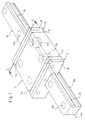
- a guide rail is generally 10 designated.
- the axis of this guide rail is designated Ax.
- the bottom of the guide rail is 10a designated and intended to be on a foundation or other carrier to be fastened by means of fastening bolts, through the guide rail 10 in vertical Stepped holes 10b passing through in the direction screwed into the foundation or base.
- On the guide rail 10 are round profile bars 10c on both sides attached, of which only one can be seen, while the others symmetrical to a vertical one containing the axis Ax Midplane is attached to the back.
- On the guide rail 10 is a guide carriage 12 in the axial direction Ax slidably guided.
- Each lubricating element carrier 14 is made of two plate-shaped Parts 16 assembled, one of which is shown in FIG. 2 is shown.
- the partial plate 16 according to FIG. 2 consists of an outer wall 18 and a system of its own over it Outer wall elevating ribs 20.
- the outer wall 18 closes an inner contour 22 which is the outer contour of the guide rail 10 is approximately adapted.
- rib system 20 abuts against rib system 20, so that between the each other 18 cavities formed at a distance from opposite outer walls are.
- These lubricant sockets 26 each have a guide 24 complementary jacket 26a.
- These lubricant sockets are in the middle of their lead length by one each Support plate 28 divided.
- the support plates 28 are in one piece made with the jacket 26a.
- the raceway lubricating element 34 has his facing the track 10c, over the jacket 26a protruding end a contour 36 which is the contour of the respective round profile rod 10c is adapted.
- the Support plate 28 has openings 38 which the Receiving chamber 32 with a lubricant storage chamber 40 connect.
- the lubricant reservoir is with a filled with liquid lubricant.
- the raceway lubrication element 34 fills the cross section of the receiving chamber 32 in essentially completely so that the free flow blocked by the receiving chamber 32 for the lubricant is and lubricant from the storage chamber 40 only after Permeation through the respective felt part to the surface the circular profile rod 10c can reach.
- the lubricating element holder 26 is by a helical compression spring 42 biased towards the guide rail 10.
- the helical compression spring 42 is supported a support frame 44 in the region of a rib 20a on the Lubricating element carrier 14 and on the other hand acts on the Support plate 28, which is used to center the helical compression spring 42 is formed with a centering pin 42a.
- the helical compression spring 42 Lubrication element holder 26 in the direction of the guide rail 10 pressed and in the direction of the guide rail protruding end of the raceway lubricating element with the profile contour 36 to the circular Round profile bar 10c.
- the pantries 40 to both Sides of the inner profile contour 22 are over Lubricant supply channels 46 to a lubricant inflow point 48 connected, in detail from Fig. 3 to is seen.
- Welding can then easily take place in these plant areas between the two plate-shaped parts 16 be made.
- round ribs 54 of the rib system are also formed, whose height is the height of the remaining rib system 20 corresponds so that these round ribs 54 at Combining the two plate-shaped parts 16 together come to rest and are also welded together.
- the lubricant connection 48 is by ring ribs 58 formed on the two plate-shaped partial bodies 16, the also abut each other and welded together become. Each of these ring ribs has an axial notch 60. These notches 60 together form a connection 64 (see FIG. 3) from the through opening 62 of the Lubricant connection 48 to the lubricant supply channel 46, which the lubricant storage chambers 40 with connects the lubricant connection 48.
- the passage opening 62 can be closed at one end and at the other end with connected to a nipple in the form of a check valve be that allows injection of lubricant, one Outflow prevented.
- annular groove 66 is inserted into the inner circumferential surface of the guide 24 can be.
- annular groove 66 is one Half provided in each of the two plate-shaped parts 16.
- the annular groove 66 receives a sealing ring 68.
- the socket housing 26 each have a stop at its end remote from the guide rail 26c has after pulling off the carriage 12 from the guide rail 10 or after removal of the lubricating element carrier 14 from the guide carriage 12 completely push out the guide housing 26 from the Guide 24 prevented and thus the socket 26 captive connects to the lubricating element carrier 14. Still is the raceway lubrication element 34 within the socket housing 26 taken in such a tight fit that it too is captive.
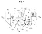
- a guide rail is designated 110 and a guide carriage guided on this guide rail with 112.
- the guide rail 110 has two side surfaces 110f, a bottom surface 110g and a top surface 110h on.
- Each of the side surfaces 110f has a trapezoidal groove 110i.
- the flanks of this trapezoidal groove are 110i designated 110k; these flanks form raceways for rows of rolls.
- the guide rail 110 is, as can be seen from FIG. 5, fastened with its bottom surface 110g on a carrier 114 and for this purpose is provided with bores 1101 at intervals along its axis A x for receiving fastening bolts.
- the guide carriage 112 is, as can be seen from FIGS. 4 and 5, with a web area 112f and leg areas 112g executed.
- the web area 112f lies on the top surface 110h opposite, while the leg regions 112g the side surfaces Face 110f.
- the guide carriage 112 is on the guide rail guided by roller loops 116 and 118.
- the load transferring roller rows 116a and 118a of these roller loops 116,118 are on the one hand on the the flanks 110k and on the other hand guided on raceways of the carriage 112.
- To the Guide carriages 112 are provided with mounting holes 112i.
- A can be in these mounting holes 112i Object to be attached to the carriage 112, for example a machine tool table.
- FIG. 5 shows a treatment element carrier 124, which consists of a carrier plate 126 and a cover 128 is composed. Carrier plate and cover 126 and 128 are penetrated by fastening holes 130, through which the bolts 122 for fastening the Treatment element carrier 124 in the carriage be screwed in.
- the lid 128 is on the carrier plate 126 with fastening screws 134 attached.
- the treatment element carrier 124 has a web part 124f and leg portions 124g which correspond to the web area 112f and the leg regions 112g of the guide carriage according to FIG. 4 assigned.
- disk-shaped guide chambers 136 are recessed in relief in each of the leg parts 124g. These guide chambers 136 are designed with a main surface 136a orthogonal to the axis A x and with edge surfaces 136b and 136c. In addition, the disk-shaped guide chambers 136 are covered by the cover 128. Disc-shaped treatment elements 140 are guided in the disk-shaped guide chambers 136, specifically through the main surface 136a, the cover 128 and the edge surfaces 136b. The disk-shaped rail treatment elements 140 have scraping edges 142 which are designed and designed for scraping the raceways 110k. The scraping edges 142 are pressed against the raceways 110k by prestressing bodies 144.
- the biasing body 144 consist of plastic discs of circular cylindrical outline. Elastically compressible O-rings 144b made of elastomeric material, for example natural rubber, are inserted into the peripheral surfaces of the plastic disks 144a. The plastic disks 144a rest on the main surface 136a and on the cover 128 in a freely movable manner.
- semicircular recesses 146 are formed adjacent to its edge 148 remote from the rail and loosely accommodate and position the prestressing bodies 144.
- segment-shaped troughs 149 are formed for positioning the biasing bodies 144 in the edge surface 136c of the disk-shaped guide chamber.
- the prestressing bodies 144 press the rail treatment element 140 with its scraping edges 142 against the raceways 110k of the guide rail 110.
- the O-rings 144b are accommodated in an elastically compressed manner between the cutouts 146 and the troughs 149.
- the scraping edges 142 are precisely adapted to the profile profile of the side surface 110f of the guide rail 110, also to the extent that the guide rail has fine structures, for example at 110 m.
- the fine structure at 110m can be intended to be encompassed by a cover plate of the head surface 110b, which covers the entire head surface 110h, in order to also provide a uniform surface structure of the head surface 110a in the region of the fastening bores 1101.
- the guide rail 110 engages with the scraper edges 142 of the rail treatment element 140 in the entire height range h in which the guide rail 112 is overlapped by the guide carriage.
- the rail treatment element 140 do not emerge from the disk-shaped guide chamber 136.
- securing means in the form of an elongated hole 150 of the rail treatment element 140 and an elongated hole engaging bolt 152 are provided, which from the main surface 136a of the disc-shaped Guide chamber 136 penetrates the elongated hole 150 starting.
- the slot 150 has opposite the slot engagement pin 152 a certain side game in all directions.
- the side game is in the through the edge surfaces 136b predetermined guiding direction H so that on the one hand when the carriage 112 on the guide rail 110 is attached, the pressing of Scraper edges 142 on the raceways 110k are not hindered and that, on the other hand, when the guide carriage 112 is withdrawn from the guide rail 110, the rail treatment element 140 through the expansion effect of elastically compressed O-rings 144b not out of the guide pushed out through the disk-shaped guide chamber 136 can be.
- the carrier plate 126 has a disk-shaped guide chamber 156 on which by a main surface 156a and Edge areas 156b, 156c is limited and in turn by the Lid 128 is completed.
- this disc-shaped Guide chamber 156 is a rail treatment element 158 for the head surface 110h of the rail 110 or its cover plate housed.
- This rail treatment element 158 is by means of biasing body 144 with a scraping edge 160 pressed against the head surface 110h of the guide rail 110.
- the storage of the biasing body 144 within the disk-shaped guide chamber 156 corresponds to the storage of the Bias body 144 within the guide chamber 136.
- Das Pushing out the rail treatment element 158 from the disc-shaped guide chamber 156 is through an elongated hole-bolt combination 150,152 prevented their effect is the same as in the case of the rail treatment element 140.
- Fig. 5 it can be seen that the rail treatment elements 140 and 158 in an overlap area U on the edge between the side surface 110f and the head surface 110h overlap. This overlap is necessary around the surface of the guide rail 110 also in this subjecting the critical area to a scraping treatment.
- the overlap is made possible by the treatment element 158 adjacent to the scraping edge 160 a Has recess 164, in which the upper edge regions 166 of the treatment elements 140 engage.
- the Overlap can be seen in particular in FIG. 9.
- the scraping edge 142 can be seen in section in FIG. 18a.
- the side surface 140x is closer to the guide carriage, while the side surface 140y of the treatment element 140 is further away from the guide carriage. It can be seen that the scraping edge 142 is also arranged in the surface 140y away from the guide carriage.
- the scraper edge 142 serves to scrape chips and other contaminants from the tread, even if they adhere firmly to the tread 110k.
- the chips are indicated at 167 in FIG. 18a; they are scraped off when the guide carriage, not shown in FIG. 18a and lying on the right side of the treatment element 140, is moved in the direction of movement B parallel to the rail axis A x .
- FIG. 18c shows yet another embodiment in which the scraper edge 142 "of a treatment element 140" is formed at the tip of a scoop surface 168 ".
- the scoop surface 168" is by a notch 170 "in the side surface 140 remote from the guide carriage “y shaped.
- the blade surface 168 "and the edge 142" in the axial direction A x are essentially rigid with respect to the body of the treatment element 140 ".
- the notch 170" means that the blade surface 168 "and the scraping edge 142" in the direction C. compliant if the notch 170 "is arranged correspondingly deep.
- a geometry can be seen in the embodiment according to FIG. 18d of the treatment element 140, which differs from that 18a differs only in that the angle ⁇ is made more acute than in Fig. 18a.
- FIG. 18e finally shows a modification in which the notch 170 "'has a circular cross section instead of the triangular cross section according to FIG. 18c.
- a scoop surface 168"' is formed adjacent to the scraper edge 142 ".
- the scraper edge can also be used here 142 "'with appropriate dimensioning of the notch 170"' be elastic in direction C.
- the scraping edge is again essentially rigid with respect to the rail treatment element 140 "'.
- scraping edge If one speaks of a scraping edge, it should be said that this scraping edge is suitable, contamination, also adhering impurities from which respective career or other treated area of the Scrape off the guide rail. It’s less thought Scrape material of the guide rail 110 from the latter.
- the carrier plate 126 and the cover 128 In the manufacture of the carrier plate 126 and the cover 128 you can also use metallic materials, especially Materials that process using the die casting process to guide the guide chambers 136 and 156 easy to train. But you can also for the production of the carrier plate 126 and the cover 128 Use plastics, especially by injection molding.
- the assembly of the guide carriage 112 on the guide rail 110 can be done after the treatment center 120 is already on screwed to the carriage 112 by the screws 122 has been.
- the application of the carriage with the screwed-on treatment units 120 onto the guide rail 110 can then be facilitated in that the Guide rail with chamfered guide surfaces at its ends which has the treatment elements 158 and 140 at Pushing the carriage 112 inevitably against the Push back action of the elastic biasing body 144.
- the carriages it is also possible to fundamentally the carriages to deliver together with a guide piece whose Length approximately the same or preferably slightly larger than the length of the carriage.
- This guide piece can in turn be chamfered at one end be carried out so that the assembly of the carriage is facilitated with the guide piece.
- the Guide piece will then be on its with the guide rail crashing end so formed that it is as possible forms a smooth transition to the guide rail.
- the carriage can then run from the one to the Guide rail held guide piece on the guide rail be pushed over without this being pushed over through on towards the guide piece and later on the guide rail pre-stressed treatment elements hindered becomes.
- the application of the treatment units already assembled carriage on the guide rail can also be facilitated by positioning means or holding means can be provided around the treatment elements 140 and 158 initially in an ineffective Hold position.
- positioning means or holding means can be provided around the treatment elements 140 and 158 initially in an ineffective Hold position.
- a filling piece 170 can be pressed in when one is in the cover 128 11 provides a filler insertion opening 172.
- the rail treatment elements are then formed by this filler 170 140 and 158 in an ineffective position held in which the carriage 112 without disability through the rail treatment elements 140 and 158 to the Guide rail can be pushed on.
- the principle of positioning the rail treatment elements through or holding means in an ineffective position hold until the carriage is mounted on the guide rail or until the assembly of the rail treatment units on the guide carriage already attached to the guide rail has ended, can also in other embodiments of rail treatment units with in Direction of rail treatment elements prestressed on the guide rail apply, for example to Rail treatment elements, which according to the European patent application 512 253 A1 with lamellar Rail treatment elements are executed (cf. there Fig. 5, position 9). You could see the lamellar there Rail treatment elements for example a wire or plastic cord in an ineffective position hold in which they are angled so far that when pushing the carriage onto the guide rail do not collide with the guide rail. If the carriage is then attached to the guide rail, so you could just use the wires or plastic threads pinch off and thereby achieve that the slats then come to rest on the guide rail.
- the scraping edge 142 of the rail treatment element 140 is exactly adapted to the profile profile of the guide rail 110 in the region of its side surface 110f.
- the guide rails 110 are manufactured with the highest precision in order to achieve correspondingly precise guides for guided objects in a higher-level machine. Accuracy on the order of a few microns must be considered. It is not difficult to produce the scraping edges 142 with sufficient accuracy in order to achieve a uniform, gap-free contact of the scraping edge 142 on the side face 110f over the entire profile profile detected.
- a certain translational and rotary play can be left to the rail treatment element 140 through the edge surfaces 136b in the rail treatment element 140, which is guided orthogonally to the axial direction A x , so that the rail treatment element regardless of the accuracy of the manufacture of the edge surfaces 136b and regardless of the accuracy of the attachment of the treatment element carrier 124 with its scraping edge 142 can adapt exactly to the profile of the side surfaces 110f.
- This measure is particularly advantageous if the profile of the rail and the scraping edge 142 deviate from the straightness.
- the elongated hole 150 and the elongated hole engaging bolt 152 must also allow appropriate play.
- the guidance of the rail treatment element 158 to the Edge surfaces 156b can be designed accordingly.
- This plan concern in connection with the overlap, is important for ensuring that the entire profile surface of the guide rail 110 is subjected to the treatment and that no dirt particles can find passages in the overlap area U of the two rail treatment elements 140 and 158. Thanks to the design of the carrier part 126 according to FIG. 7, it is possible to make the cover 128 flat on its side lying against the rail treatment elements 140, 158.
- the linear guide device according to the invention is in any case always applicable when a carriage with rolling guide means guided on the guide rail is.
- rolling guidance means described as an example 1 and 4 is also the use of endless ball loops on the carriage is conceivable, like they are described for example in DE-OS 36 20 571.
- biasing means 144 it should be mentioned that on the plastic disc 144a can also be dispensed with.
- An O-ring 144b is sufficient to preload the rail treatment elements 140.158 to accomplish. In this The O-ring 144b must cover the distance between the main surface 136a and the cover 128 may be adapted.
Landscapes
- Engineering & Computer Science (AREA)
- General Engineering & Computer Science (AREA)
- Mechanical Engineering (AREA)
- Bearings For Parts Moving Linearly (AREA)
- Transmission Devices (AREA)
Description
- Fig. 1
- eine Übersicht über eine erfindungsgemäße Linearführungseinrichtung;
- Fig. 2
- eine Ansicht auf eine Teilplatte eines plattenförmigen Schmierelemententrägers nach der Erfindung;
- Fig. 3
- einen Schnitt nach Linie III-III der Fig. 2;
- Fig. 4
- eine Endansicht, teilweise einen Schnitt, einer weiteren erfindungsgemäßen Linearführungseinrichtung mit einer Schienenbehandlungseinheit;
- Fig. 5
- eine Endansicht einer Schienenbehandlungseinheit, teilweise geöffnet;
- Fig. 6
- eine Ansicht auf einen Behandlungselemententräger der Schienenbehandlungseinheit;
- Fig. 7
- einen Schnitt nach Linie VII-VII der Fig. 6;
- Fig. 8
- einen Schnitt nach Linie VIII-VIII der Fig. 6;
- Fig. 9
- einen Schnitt durch den Behandlungselemententräger entsprechend Linie VII-VII der Fig. 6, wobei in den Behandlungselemententräger Schienenbehandlungselemente eingesetzt sind;
- Fig. 10
- einen Schnitt nach Linie VIII-VIII der Fig. 6, wobei in den Behandlungselemententräger die Schienenbehandlungselemente eingesetzt sind;
- Fig. 11
- eine Ansicht eines Deckels für den Behandlungselemententräger gemäß Fig. 6;
- Fig. 12
- einen Schnitt nach Linie XII-XII der Fig. 11;
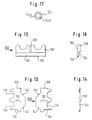
- Fig. 13
- eine Ansicht der Schienenbehandlungselmente für die Seitenflächen der Führungsschiene;
- Fig. 14
- eine Ansicht in Pfeilrichtung XIV der Fig. 13;
- Fig. 15
- eine Ansicht eines Schienenbehandlungselements für die Kopffläche der Führungsschiene;
- Fig. 16
- eine Ansicht in Pfeilrichtung XVI der Fig. 15;
- Fig. 17
- die Ansicht eines Vorspannelements für die Schienenbehandlungselemente und
- Fig. 18a - 18e
- verschiedene Schabekantengestaltungen an Schienenbehandlungselementen.
Claims (97)
- Linearführungseinrichtung, umfassend eine Führungsschiene (10;110) mit einer Achse (Ax) und mindestens einer Laufbahn (10c;110k) und mindestens einen Führungswagen (12;112) mit mindestens einem im Betriebszustand an dieser Laufbahn (10c;110k) geführten Laufelement (12a;116a), wobei an dem Führungswagen (12;112) ein Behandlungselemententräger (14;124) für mindestens ein Schienenbehandlungselement (34;140,158), insbesondere ein Laufbahnbehandlungselement (34;140,158), angebracht ist, und wobei dieses Schienenbehandlungselement (34;140,158) an dem Behandlungselemententräger (14;124) in einer im wesentlichen achsnormalen Ebene durch Führungsmittel (24;136,156) geführt und gegen die Führungsschiene (10;110) vorgespannt ist,
dadurch gekennzeichnet,
daß das Schienenbehandlungselement (34;140,158) in den Führungsmitteln (24;136,156) des Behandlungselemententrägers (14;124) durch Verlustsicherungsmittel (26c;150,152) gesichert ist, welche von der Führungsschiene (10;110) unabhängig sind. - Einrichtung nach Anspruch 1,
dadurch gekennzeichnet,
daß der Behandlungselemententräger als ein Schmierelemententräger (14) für ein Laufbahnschmierelement (34) ausgebildet ist, daß dieses Laufbahnschmierelement (34) aus einem Schmiermittel verteilenden und bezüglich der Laufbahn (10c) anschmiegfähigen Werkstoff besteht und daßdieses Laufbahnschmierelement (34) mit einem Schmiermittelvorrat des Schmierelemententrägers (14) in Verbindung steht, wobei das Laufbahnschmierelement (34) in einer Schmierelementenfassung (26) unverlierbar aufgenommen ist und die Schmierelementenfassung (26) in dem Schmierelemententräger (14) ebenfalls unverlierbar aufgenommen und in einer zur Achse (Ax) im wesentlichen orthogonalen Richtung beweglich geführt und in Richtung auf die Laufbahn (10c) vorgespannt ist. - Einrichtung, nach Anspruch 2,
dadurch gekennzeichnet,
daß der Schmiermittelvorrat außerhalb der Schmierelementenfassung (26), jedoch innerhalb des Schmierelemententrägers (14) untergebracht ist und daß eine Schmiermittelverbindung (38) zwischen dem Schmiermittelvorrat (40) und dem innerhalb der Schmierelementenfassung (26) aufgenommenen Laufbahnschmierelement (34) besteht. - Einrichtung nach Anspruch 3,
dadurch gekennzeichnet,
daß die Schmierelementenfassung (26) ein Fassungsgehäuse (26) aufweist mit einem zu der Führungsrichtung (24) der Schmierelementenfassung (26) im wesentlichen parallelen Mantelfläche (26a), wobei dieses Fassungsgehäuse (26) ein zur Laufbahn hin offenes Ende (30) aufweist und das Laufbahnschmierelement (34) über dieses offene Ende (30) in Richtung auf die Laufbahn (10c) hin vorsteht. - Einrichtung nach Anspruch 4,
dadurch gekennzeichnet,
daß das Fassungsgehäuse (26) an seinem laufbahnfernen Ende eine öffnung besitzt, welche in Verbindung mit dem Schmiermittelvorrat (40) steht. - Einrichtung nach Anspruch 4 oder 5,
dadurch gekennzeichnet,
daß das Fassungsgehäuse (26) durch eine an seiner Mantelfläche (26a) anliegende, im wesentlichen ringsum anliegende, Dichtstelle (66, 68) des Schmierelemententrägers hindurchgeführt ist. - Einrichtung nach einem der Ansprüche 2 bis 6,
dadurch gekennzeichnet,
daß die Schmierelementenfassung (26) einen Anschlag (26c) besitzt, welcher im Zusammenwirken mit einem Gegenanschlag des Schmierelemententrägers (14) die Beweglichkeit der Schmierelementenfassung (26) in Richtung auf die Laufbahn begrenzt. - Einrichtung nach Anspruch 7,
dadurch gekennzeichnet,
daß bei Ausführung der Schmierelementenfassung (26) mit einem Fassungsgehäuse (26) der Anschlag (26c) von einem auswärts abstehenden Bund des Fassungsgehäuses (26) an dessen laufbahnfernem Ende gebildet ist. - Einrichtung nach einem der Ansprüche 4 bis 8,
dadurch gekennzeichnet,
daß das Fassungsgehäuse (26) an mittlerer Stelle seiner in seiner Führungsrichtung (24) verlaufenden Länge ein Stützglied (28) aufweist, welches einerseits als Anschlag für das von dem laufbahnnahen Ende her in das Fassungsgehäuse (26) eingeführte Laufbahnschmierelement (34) und andererseits als Anschlag für eine Vorspannfeder (42) dient, welche an dem Schmierelemententräger (14) abgestützt ist. - Einrichtung nach Anspruch 9,
dadurch gekennzeichnet,
daß das Stützglied (28) mit einem Zentrierdorn (42a) für eine Schraubendruckfeder (42) ausgeführt ist. - Einrichtung nach einem der Ansprüche 9 und 10,
dadurch gekennzeichnet,
daß das Stützglied (28) nur einen Teil des Querschnitts des Fassungsgehäuses (26) ausfüllt und Durchgänge (38) für das Schmiermittel innerhalb des Fassungsgehäuses frei läßt. - Einrichtung nach einem der Ansprüche 2 bis 11,
dadurch gekennzeichnet,
daß das Laufbahnschmierelement (34) innerhalb der Schmierelementenfassung (26) im Reibsitz aufgenommen ist. - Einrichtung nach einem der Ansprüche 2 bis 12,
dadurch gekennzeichnet,
daß das Laufbahnschmierelement (34) von porösem, schmiermittelleitendem Werkstoff gebildet ist. - Einrichtung nach einem der Ansprüche 2 bis 13,
dadurch gekennzeichnet,
daß das Laufbahnschmierelement (34) von einem Filzkörper gebildet ist. - Einrichtung nach einem der Ansprüche 13 und 14,
dadurch gekennzeichnet,
daß das Laufbahnschmierelement (34) in einer als Fassungsgehäuse (26) ausgebildeten Schmierelementenfassung (26) im wesentlichen den gesamten Gehäusequerschnitt ausfüllt. - Einrichtung nach einem der Ansprüche 2 bis 15,
dadurch gekennzeichnet,
daß das Laufbahnschmierelement (34) mit einer derartigen Schmiermittelleitfähigkeit bezogen auf die Viskosität des jeweils eingesetzten Schmiermittels ausgeführt ist, daß im wesentlichen kein Schmiermittelverlust in Richtung senkrecht zur Führungsrichtung (24) des Laufbahnschmierelements eintritt. - Einrichtung nach einem der Ansprüche 2 bis 16,
dadurch gekennzeichnet,
daß bei Vorhandensein mehrerer Laufbahnen (10c) an der Führungsschiene (10) an ein und demselben Schmierelemententräger (14) in Zuordnung zu jeder dieser Laufbahnen (10c) mindestens ein Laufbahnschmierelement (34) vorgesehen ist. - Einrichtung nach Anspruch 17,
dadurch gekennzeichnet,
daß an ein und demselben Schmierelemententräger (14) zwei einander gegenüberstehende Laufbahnschmierelemente (34) vorgesehen sind, wobei deren Schmierelementenfassungen (26) annähernd miteinander fluchtende Führungsrichtungen aufweisen. - Einrichtung nach einem der Ansprüche 2 bis 18,
dadurch gekennzeichnet,
daß der Schmierelemententräger (14) als ein plattenförmiges Gebilde ausgebildet ist, welches an einer zur Achse der Führungsschiene im wesentlichen orthogonalen Stirnfläche (12c) des Führungswagens (12) angebracht ist. - Einrichtung nach Anspruch 19,
dadurch gekennzeichnet,
daß der Schmierelemententräger (14) eine innere Umfangskontur (22) besitzt, welche annähernd dem Außenquerschnitt der Führungsschiene (10) angepaßt ist und an dieser gegebenenfalls über eine der Kontur folgende Dichtung anliegt, wobei das mindestens eine Laufbahndichtungselement über diese Umfassungskontur in Richtung auf die jeweilige Laufbahn vorsteht. - Einrichtung nach einem der Ansprüche 2 bis 20,
dadurch gekennzeichnet,
daß innerhalb des Schmierelemententrägers (14) eine Lebensdauerfüllung von Schmiermitteln enthalten ist. - Einrichtung nach einem der Ansprüche 2 bis 21,
dadurch gekennzeichnet,
daß der Schmiermittelvorrat (40) mit einem Schmiermittelanschluß (48) für ein Schmiermittelnachfüllgerät ausgebildet ist, vorzugsweise in Form eines Schmiernippels mit Rückschlagwirkung. - Einrichtung, nach einem der Ansprüche 2 bis 22,
dadurch gekennzeichnet,
daß bei Anordnung mehrerer Laufbahnschmierelemente (34) an einem gemeinsamen Schmierelemententräger (14) diese mit einem gemeinsamen Schmiermittelvorrat (40, 46) in Verbindung stehen. - Einrichtung nach einem der Ansprüche 2 bis 23,
dadurch gekennzeichnet,
daß der Schmierelemententräger (14) als ein Flachgehäuse ausgebildet ist, welches an mindestens einer zur Achsrichtung (Ax) der Führungsschiene (10) im wesentlichen orthogonalen Endfläche (12c) des Führungswagens (12) als gesondertes Bauteil des Führungswagens-gewünschtenfalls lösbar-befestigt ist. - Einrichtung nach Anspruch 24,
dadurch gekennzeichnet,
daß das Flachgehäuse aus zwei sandwichartig aneinander anliegenden Flachgehäuseteilen (16) zusammengesetzt ist. - Einrichtung nach Anspruch 25,
dadurch gekennzeichnet,
daß die Flachgehäuseteile (16) von jeweils einer Hauptwand (18) und von über dieser Hauptwand (18) sich orthogonal zu dieser erhebenden Rippen (20) gebildet ist, welche im zusammengebauten Zustand in bezug auf eine gemeinsame zu den Hauptwänden (18) parallele Mittelebene prinzipiell spiegelsymmetrisch ausgebildet sind. - Einrichtung nach Anspruch 26,
dadurch gekennzeichnet,
daß die Flachgehäuseteile (16) identisch ausgebildet sind. - Einrichtung nach Anspruch 27,
dadurch gekennzeichnet,
daß an in zusammengebautem Zustand des Flachgehäuses aneinander anliegenden Rippenkopfflächen (20) der Rippen Dicht- und/oder Verbindungsmittel jeweils nur über einen Halbbereich der Flachgehäuseteile (16) angeordnet sind derart, daß sich diese im zusammengebauten Zustand über die gesamte Berührungsfläche der Flachgehäuseteile (16) verteilt ergänzen. - Einrichtung nach einem der Ansprüche 25 bis 28,
dadurch gekennzeichnet,
daß die Flachgehäuseteile (16) miteinander verschweißt, insbesondere ultraschallverschweißt oder verklebt sind. - Einrichtung nach einem der Ansprüche 2 bis 29,
dadurch gekennzeichnet,
daß der Schmierelemententräger (14) als ein den Schmiermittelvorrat (bei 40) und Schmiermittelleitungswege (46) nach außen dicht abschließendes Gehäuse ausgebildet ist, welches einen Schmiermittelaustritt nur im Bereich des mindestens einen Laufbahnschmierelements (34) aufweist. - Einrichtung nach Anspruch 30,
dadurch gekennzeichnet,
daß das Gehäuse eine Füllstelle (48) zum Einfüllen von Schmiermittel aufweist. - Einrichtung nach Anspruch 31,
dadurch gekennzeichnet,
daß die Füllstelle (48) mit einem lösbaren Verschluß oder einem Rückschlagnippel ausgeführt ist. - Einrichtung nach Anspruch 32,
dadurch gekennzeichnet,
daß die Füllstelle (48) an einem betriebsmäßig oberhalb des Schmiermittelvorrats (40) liegenden Ort angeordnet ist. - Einrichtung nach einem der Ansprüche 30 bis 32,
dadurch gekennzeichnet,
daß das Gehäuse aus zwei unter Vermittlung von Dichtbereichen aneinander anliegenden Gehäuseteilen besteht. - Einrichtung nach Anspruch 34,
dadurch gekennzeichnet,
daß die Gehäuseteile von Befestigungsöffnungen (56) zur Befestigung an dem Führungswagen (12) durchsetzt sind und daß die Gehäuseteile auch im Umgebungsbereich dieser Befestigungsöffnungen (56) gegeneinander abgedichtet sind. - Einrichtung nach einem der Ansprüche 30 bis 35,
dadurch gekennzeichnet,
daß an den Gehäuseteilen (16) Halbaufnahmekammern (66) für die Aufnahme jeweils der Hälfte eines Dichtrings (68) angeordnet sind, welcher Dichtring (68) von der jeweiligen Schmierelementenfassung (26) durchsetzt wird. - Einrichtung nach einem der Ansprüche 1 bis 36,
dadurch gekennzeichnet,
daß das mindestens eine Laufelement von einer Laufrolle (12a) gebildet ist. - Einrichtung nach Anspruch 37,
dadurch gekennzeichnet,
daß die Laufrolle (12a) eine konkave Mantelfläche besitzt, welche mit einem komplementären, die Führungsbahn bildenden Profil in Eingriff steht. - Einrichtung nach Anspruch 38,
dadurch gekennzeichnet,
daß das Profil (10c) von einer Rundprofilstange mit annähernd Kreisquerschnitt gebildet ist, welche auf einer Trägerschiene befestigt ist. - Einrichtung nach einem der Ansprüche 1 bis 39,
dadurch gekennzeichnet,
daß der Führungswagen (12) die Führungsschiene (10) angenähert U-förmig umgreift und daß an den beiden Schenkeln des U-förmig umgreifenden Führungswagens (12) jeweils mindestens eine Laufrolle (12a) angeordnet ist. - Einrichtung, nach einem der Ansprüche 1 bis 40,
dadurch gekennzeichnet,
daß der als Schmierelemententräger (14) ausgebildete Behandlungselemententräger ein dicht abgeschlossenes Gehäuse umfaßt, welches den Schmiermittelvorrat (40) enthält und daß dieses dicht abgeschlossene Gehäuse als Ausgang lediglich einen Durchtritt für einen Teil des mindestens einen als Laufbahnschmierelement (34) ausgebildeten Schienenbehandlungselements aufweist, wobei dieser Durchtritt durch das Laufbahnschmierelement (34) im wesentlichen vollständig abgeschlossen ist, so daß ein Schmiermittelaustritt lediglich durch Schmiermittelpermeation innerhalb des Laufbahnschmierelements (34) möglich ist. - Einrichtung nach einem der Ansprüche 1 - 41,
dadurch gekennzeichnet,
daß das Schienenbehandlungselement (34;140,158) innerhalb des Behandlungselemententrägers (14;124) durch Geradführungsmittel (24;136,156) geführt ist. - Einrichtung nach einem der Ansprüche 1 - 42,
dadurch gekennzeichnet,
daß das Schienenbehandlungselement (34;140,158) Anschlagmittel (26c;150) besitzt, welche im Zusammenwirken mit Gegenanschlagmitteln (152) des Behandlungselemententrägers (14; 124) die durch die Führungsmittel (24;136,156) belassene Beweglichkeit des Schienenbehandlungselements (34;140,158) beschränken. - Einrichtung nach einem der Ansprüche 1 - 43,
dadurch gekennzeichnet,
daß an ein und demselben Behandlungselemententräger (14;124) Führungsmittel (24;136,156) für eine Mehrzahl von Schienenbehandlungselementen (34;140,158) vorgesehen sind. - Einrichtung nach Anspruch 44,
dadurch gekennzeichnet,
daß an ein und demselben Behandlungselemententräger (14;124) zwei einander gegenüberstehende Schienenbehandlungselemente (34;140) vorgesehen sind. - Einrichtung nach einem der Ansprüche 1 - 45,
dadurch gekennzeichnet,
daß der Behandlungselemententräger (14;124) zusammen mit mindestens einem Schienenbehandlungselement (34;140,158) zu einer im wesentlichen vollständig vormontierten Baueinheit zusammengefaßt ist und daß an dieser Baueinheit Befestigungsmittel (56;130) vorgesehen sind, welche die Befestigung an dem Führungswagen (12;112) gestatten. - Einrichtung nach einem der Ansprüche 1 - 46,
dadurch gekennzeichnet,
daß der Behandlungselemententräger (14;124) mit einer im wesentlichen planen Anlagefläche zum Anbau an einer zur Achse (Ax) des Führungswagens (12;112) im wesentlichen orthogonalen Stirnfläche des Führungswagens (12;112) ausgeführt ist und daß der Behandlungselemententräger (14;124) mit im wesentlichen orthcgonal zu der Anlagefläche verlaufenden Befestigungslöchern (56;130) versehen ist, welche die Befestigung der Baueinheit an der Stirnfläche des Führungswagens (12;112) mittels die Baueinheit durchsetzender, in den Führungswagen (12;112) eingreifender Befestigungsbolzen (122) gestatten. - Einrichtung nach einem der Ansprüche 1 - 47,
dadurch gekennzeichnet,
daß der Behandlungselemententräger (14;124) als ein im wesentlichen planparalleler Flachkörper ausgebildet ist. - Einrichtung nach einem der Ansprüche 1 - 48,
dadurch gekennzeichnet,
daß der Behandlungselemententräger (14;124) als ein Gehäuse ausgebildet ist, wobei innerhalb dieses Gehäuses (14;124) die Führungsmittel (24;136,156) für das mindestens eine Schienenbehandlungselement (34;140,158) untergebracht sind. - Einrichtung nach einem der Ansprüche 1 - 49,
dadurch gekennzeichnet,
daß der Behandlungselemententräger (14;124) als ein im wesentlichen planparalleles Flachgehäuse ausgebildet ist. - Einrichtung nach einem der Ansprüche 1 - 50,
dadurch gekennzeichnet,
daß der Behandlungselemententräger (14;124) aus zwei sandwichartig aneinander anliegenden Trägerteilen (16;126,128) zusammengesetzt ist. - Einrichtung nach Anspruch 51,
dadurch gekennzeichnet,
daß die Führungsmittel (136,156) im Bereich von Berührungsflächen der sandwichartig aneinander anliegenden Trägerteile (126,128) angeordnet sind, insbesondere in der Weise, daß das mindestens eine Schienenbehandlungselement (140,158) und ihm zugehörige Vorspannmittel (144) nach Einlegen in Führungsmittel (136,156) des einen Trägerteils (126) durch Aneinanderanlegen der Berührungsflächen beider Trägerteile (126,128) und durch Befestigung der beiden Trägerteile (126,128) aneinander gegen Trennung von dem Behandlungselemententräger (124) gesichert sind. - Einrichtung nach Anspruch 51 oder 52,
dadurch gekennzeichnet,
daß die beiden Trägerteile (16;126,128) durch Verschweißen, insbesondere Ultraschallverschweißen, oder Verkleben oder Verschrauben oder Ineinanderrasten miteinander verbunden sind. - Einrichtung nach einem der Ansprüche 1 - 53,
dadurch gekennzeichnet,
daß der Führungswagen (12;112) in Längsrichtung der Achse (Ax) betrachtet im wesentlichen U-förmig ausgebildet ist mit einem einer Kopffläche (110h) der Führungsschiene (10;110) nahe liegenden Stegbereich (112f) und zwei je einer Seitenfläche (110f) der Führungsschiene (10;110) nahe liegenden Schenkelbereichen (112g). - Einrichtung nach Anspruch 54,
dadurch gekennzeichnet,
daß der U-förmige Führungswagen (12;112) durch je ein Rollmittelsystem (12a;116,118) zwischen den beiden Schenkelbereichen (112g) und der jeweils zugehörigen Seitenfläche (110f) der Führungsschiene (10;110) geführt ist. - Einrichtung nach Anspruch 55,
dadurch gekennzeichnet,
daß die Rollmittelsysteme (12a;116,118) an dem Führungswagen (12;112) angebracht sind und mit Laufbahnen (10c;110k) an den beiden Seitenflächen (110f) der Führungsschiene (10;110) in rollendem Eingriff stehen. - Einrichtung nach Anspruch 56,
dadurch gekennzeichnet,
daß die Rollmittelsysteme von an dem Führungswagen (12) einzeln gelagerten Rollen (12a) gebildet sind, welche an ihren Umfangsflächen mit Laufbahnen (10c) in rollendem Eingriff stehen. - Einrichtung nach Anspruch 56,
dadurch gekennzeichnet,
daß die Rollmittelsysteme (116,118) von an dem Führungswagen (112) geführten endlosen Wälzkörperreihen (116,118) gebildet sind. - Einrichtung nach einem der Ansprüche 1 - 58,
dadurch gekennzeichnet,
daß das Schienenbehandlungselement als ein Abstreifelement ausgebildet ist, welches etwaigen Schmutz von der Führungsschiene abstreift, wenn sich der Führungswagen längs der Führungsschiene bewegt. - Einrichtung nach einem der Ansprüche 1 - 59,
dadurch gekennzeichnet,
daß bei U-förmiger Ausführung des Führungswagens (12;112) der Behandlungselemententräger (14;124) ebenfalls U-förmig ausgebildet ist mit einem einer Kopffläche (110h) der Führungsschiene (10;110) gegenüberliegenden Stegteil (124f) und mit Seitenflächen (110f) der Führungsschiene (10;110) gegenüberliegenden Schenkelteilen (124g). - Einrichtung nach Anspruch 60,
dadurch gekennzeichnet,
daß in jedem der Schenkelteile (124g) jeweils ein Schienenbehandlungselement (34;140) zum Eingriff mit der jeweils zugehörigen Seitenfläche (110f) vorgesehen ist. - Einrichtung nach einem der Ansprüche 1 - 61,
dadurch gekennzeichnet,
daß an zwei in Achsrichtung voneinander abgelegenen Stirnflächen (12c;112k) des Führungswagens (12;112) je ein Behandlungselemententräger (14;124) angebracht ist. - Einrichtung nach einem der Ansprüche 1 - 62,
dadurch gekennzeichnet,
daß das Schienenbehandlungselement (140,158) als ein Schabelement zum Abschaben von ggf. anhaftenden Verunreinigungen (167) von der Führungsschiene (110) ausgebildet ist. - Einrichtung nach einem der Ansprüche 1 - 63,
dadurch gekennzeichnet,
daß das mindestens eine Schienenbehandlungselement (140, 158) bei Betrachtung des Führungsschienenprofils in Achsrichtung (Ax) der Führungsschiene (110) über eine zugehörige Laufbahn (110k) hinaus in Behandlungseinwirkung mit der Führungsschiene (110) steht. - Einrichtung nach Anspruch 64,
dadurch gekennzeichnet,
daß das gesamte Profil der Führungsschiene (110), zumindest innerhalb des von einem Führungswagen (112) bedeckten Profilbereichs, der Einwirkung von Schienenbehandlungselementen (140,158) ausgesetzt ist. - Einrichtung nach einem der Ansprüche 1 - 65, bei der an dem Führungswagen (112) mindestens zwei Schienenbehandlungselemente (140,158) in einer zur Achse im wesentlichen orthogonalen Ebene beweglich angeordnet und gegen die Führungsschiene (110) vorgespannt sind derart, daß sie mit jeweils einer Anlagekante (142,160) einem Umfangsabschnitt des Führungsschienenprofils anliegen,
dadurch gekennzeichnet,
daß sich die Anlagekanten (142,160) der mindestens zwei Schienenbehandlungselemente (140,158) in Profilumfangsrichtung gegenseitig überlappen. - Einrichtung nach einem der Ansprüche 1 - 66,
dadurch gekennzeichnet,
daß bei U-förmiger Ausführung des Führungswagens (112) mit einem einer Kopffläche (110h) der Führungsschiene (110) gegenüberliegenden Stegbereich (112f) und zwei je einer Seitenfläche (110f) der Führungsschiene (110) gegenüberliegenden Schenkelbereichen (112g) jedem der Schenkelbereiche (112g) ein Schienenbehandlungselement (140) für eine Seitenfläche (110f) der Führungsschiene (110) und dem Stegbereich (112f) ein Schienenbehandlungselement (158) für die Kopffläche (110h) der Führungsschiene (110) zugeordnet ist. - Einrichtung nach Anspruch 67,
dadurch gekennzeichnet,
daß sich die beiden den Seitenflächen (110f) zugeordneten Schienenbehandlungselemente (140) in Profilumlaufrichtung mit dem der Kopffläche (110h) zugeordneten Schienenbehandlungselement (158) überlappen. - Einrichtung nach einem der Ansprüche 1 - 68,
dadurch gekennzeichnet,
daß bei sandwichartiger Zusammensetzung des Behandlungselemententrägers (14;124) aus zwei Trägerteilen (16;126, 128) mit zur Achse (Ax) orthogonalen Berührungsflächen der eine (16;126) dieser Trägerteile (16;126,128) in seiner Berührungsfläche reliefartig mit einer Führungsausnehmung (24;136,156) für das mindestens eine Schienenbehandlungselement (34;140,158) ausgebildet ist, wobei diese Führungsausnehmung (24;136,156) durch den jeweils anderen Trägerteil (16; 128) geschlossen ist. - Einrichtung nach Anspruch 69,
dadurch gekennzeichnet,
daß die Führungsausnehmung (136,156) durch eine zur Achse (Ax) orthogonale Hauptfläche (136a) und je zwei zueinander parallele Randflächen (136b) gebildet ist und der jeweils andre Trägerteil (128) eine weitere zur Achse (Ax) orthogonale Hauptfläche bildet. - Einrichtung nach Anspruch 70,
dadurch gekennzeichnet,
daß die Verlustsicherungsmittel (150,152) zum Sichern des jeweiligen Schienenbehandlungselements (140,158) gegen Austritt aus der Führungsausnehmung (136,156) an einer der Hauptflächen (136a,156a) vorgesehen sind. - Einrichtung nach Anspruch 71,
dadurch gekennzeichnet,
daß die Verlustsicherungsmittel (150,152) als Bolzen-Langloch-Sicherungsmittel ausgeführt sind. - Einrichtung nach Anspruch 72,
dadurch gekennzeichnet,
daß die Verlustsicherungsmittel (150,152) von einem Langloch (150) des jeweiligen Schienenbehandlungselements (140,158) und einem Langloch-Eingriffsbolzen (152) an einem Trägerteil (126) gebildet sind, wobei der Langloch-Eingriffsbolzen (152) vorzugsweise einstückig an dem jeweiligen Trägerteil (126) ausgebildet ist. - Einrichtung nach einem der Ansprüche 1 - 73,
dadurch gekennzeichnet,
daß im Bereich der Führungsmittel (24;136,156) ein von dem jeweiligen Schienenbehandlungselement (34;140,158) gesondert hergestelltes Vorspannmittel (42;144) zum Vorspannen der dem jeweiligen Schienenbehandlungselement (34;140,158) zugehörigen Schienenbehandlungskontur (36) bzw. -kante (142,160) gegen die jeweils zugehörige Führungsschiene (10;110) untergebracht ist. - Einrichtung nach einem der Ansprüche 1 - 74,
dadurch gekennzeichnet,
daß Vorspannmittel zum Vorspannen des Schienenbehandlungselements von jeweils mindestens einer Schraubendruckfeder (42) gebildet ist. - Einrichtung nach einem der Ansprüche 1 - 75,
dadurch gekennzeichnet,
daß Vorspannmittel (144) zum Vorspannen des Schienenbehandlungselements (140,158) einen zumindest an seiner Oberfläche aus elastomerem Werkstoff (144b) bestehenden Vorspannkörper (144) umfassen, welcher durch die Wirkung von Anschlagmitteln (150,152) oder durch das Anliegen des Schienenbehandlungselements (140,158) an der Führungsschiene (110) zwischen einer Widerlagerfläche (148) an dem Führungswagen (112) und einer Angriffsfläche (146) des Schienenbehandlungselements (140,158) unter elastischer Verformung des elastomeren Werkstoffs (144b) eingespannt ist. - Einrichtung nach Anspruch 76,
dadurch gekennzeichnet,
daß der Vorspannkörper (144) einen Elastomerring (144b) aufweist, welcher vorzugsweise als O-Ring ausgebildet ist. - Einrichtung nach Anspruch 77,
dadurch gekennzeichnet,
daß der Elastomerring (144b) einen Rundscheibenkörper (144a) in seinem Zentrum aufnimmt. - Einrichtung nach einem der Ansprüche 1 - 78,
dadurch gekennzeichnet,
daß das mindestens eine Schienenbehandlungselement (140, 158) in einer zur Achse der Führungsschiene (110) im wesentlichen orthogonalen, scheibenförmigen Führungskammer (136,156) geführt ist und daß in dieser scheibenförmigen Führungskammer (136,156) zwischen einer schienenfernen Endfläche (148) des Schienenbehandlungselements (140) und einer dieser schienenfernen Endfläche (148) gegenüberliegenden Begrenzungsfläche (136c) der scheibenförmigen Führungskammer (136) mindestens ein Vorspannkörper (144) eingelegt ist, welcher zwischen zwei Hauptflächen (136a,128) der scheibenförmigen Führungskammer (136) geführt und durch Aussparungen (146,149) in der schienenfernen Endfläche (148) des Schienenbehandlungselements (140) oder/und der Begrenzungsfläche (136c) in der scheibenförmigen Führungskammer (136) in Arbeitsposition gesichert ist. - Einrichtung nach einem der Ansprüche 1 + 42 - 79,
dadurch gekennzeichnet,
daß das Schienenbehandlungselement (140,158) scheibenförmig ausbildet und im wesentlichen orthogonal zur Achse (Ax) der Führungsschiene (110) angeordnet ist und an einem der Führungsschiene (110) nahen Rand eine Schabkante (142,160) aufweist, welche in Achsrichtung (Ax) der Führungsschiene (110) gegenüber dem Führungswagen (112) im wesentlichen starr ist. - Einrichtung nach Anspruch 80,
dadurch gekennzeichnet,
daß die Schabkante (142) im Bereich einer von dem Führungswagen (112) fernen Endfläche (140y) des scheibenförmigen Schienenbehandlungselements (140) angeordnet ist. - Einrichtung nach Anspruch 80 oder 81,
dadurch gekennzeichnet,
daß angrenzend an die Schabkante (142') eine von dem Laufwagen (112) weg weisende Schaufelfläche (168) an dem Schienenbehandlungselement (140) ausgebildet ist. - Einrichtung nach Anspruch 82,
dadurch gekennzeichnet,
daß die Schaufelfläche (168) an einem von dem Führungswagen (112) weg weisenden Vorsprung des scheibenförmigen Schienenbehandlungselements (140') ausgebildet ist. - Einrichtung nach Anspruch 82,
dadurch gekennzeichnet,
daß die Schaufelfläche (168") durch eine Einkerbung (170") in dem scheibenförmigen Schienenbehandlungselement (140") gebildet ist. - Einrichtung nach einem der Ansprüche 80 - 84,
dadurch gekennzeichnet,
daß die Schabkante (142") in zur Achsrichtung (Ax) der Führungsschiene (110) orthogonaler Richtung (C) elastisch auslenkbar an einer Scheibenstruktur des Schienenbehandlungselements (140") angebracht ist. - Einrichtung nach einem der Ansprüche 80 - 85,
dadurch gekennzeichnet,
daß von zwei einander in Profilumlaufrichtung der Führungsschiene (110) überlappenden Schienenbehandlungselementen (140,158) das eine (158) mit einer Randaussparung (164) versehen ist, welche von dem jeweils anderen (140) teilweise ausgefüllt ist. - Einrichtung nach einem der Ansprüche 1 - 86,
dadurch gekennzeichnet,
daß der Behandlungselemententräger (14;124) von mindestens einem aus Kunststoff gegossenen oder gespritzten Formteil (16;126,128) gebildet ist. - Einrichtung nach einem der Ansprüche 1 - 87,
dadurch gekennzeichnet,
daß das mindestens eine Schienenbehandlungselement (34;140, 158) aus Metall, wie Stahl, Messing, Metallguß, oder aus polymerem Werkstoff, oder aus Filz hergestellt ist. - Einrichtung nach einem der Ansprüche 1 - 88,
dadurch gekennzeichnet,
daß die Führungsschiene (110) mindestens eine Seitenfläche (110f) mit einer im Querschnitt trapezförmigen Profilvertiefung aufweist, wobei die Flanken dieser Profilvertiefung Laufbahnen (110k) für je einen endlosen Rollenumlauf (116,118) bilden und daß an dem mindestens einen Schienenbehandlungselement (140) ein entsprechend trapezförmiger Vorsprung ausgebildet ist, dessen Flanken (142) zum Zusammenwirken mit den Laufbahnen (110k) bestimmt sind. - Einrichtung nach einem der Ansprüche 66 - 89,
dadurch gekennzeichnet,
daß die Schienenbehandlungselemente (140,158) im Überlappungsbereich (U) aneinander anliegen. - Einrichtung nach einem der Ansprüche 66 - 90,
dadurch gekennzeichnet,
daß die Schienenbehandlungselemente (140,158) an in Achsrichtung (Ax) der Führungsschiene (110) gegeneinander versetzten, zur Achsrichtung (Ax) im wesentlichen orthogonalen Führungsflächen (136a,156a) anliegen. - Einrichtung nach Anspruch 91,
dadurch gekennzeichnet,
daß die in axialer Richtung gegeneinander versetzten und zur Achsrichtung im wesentlichen orthogonalen Führungsflächen (136a,156a) an einem ersten (126) von zwei flach aneinander anliegenden Trägerteilen (126,128) angeformt sind, daß die Schienenbehandlungselemente (140, 158) entsprechend der Versetzung der Führungsflächen (136a,156a) unterschiedliche Dicke, in Achsrichtung gemessen, besitzen, daß in dem dickeren (158) der beiden Schienenbehandlungselemente (140,158) eine Randaussparung (164) annähernd entsprechend der Dicke des dünneren (140) der beiden Schienenbehandlungselemente (140,158) ausgebildet ist und daß das dünnere (140) der beiden Schienenbehandlungselemente (140, 158) mit einem Randbereich (166) in die Randaussparung (164) eingreift. - Einrichtung nach Anspruch 92,
dadurch gekennzeichnet,
daß das zweite (128) der beiden flach aneinander anliegenden Trägerteile (126,128) mit einer gemeinsamen Planfläche an den beiden Schienenbehandlungselementen (140,158) anliegt. - Einrichtung nach einem der Ansprüche 66 - 93,
dadurch gekennzeichnet,
daß mindestens eines (140) der Schienenbehandlungselemente (140,158) in zur Achsrichtung (Ax) orthogonaler Ebene ein Führungsspiel besitzt, welches ungeachtet der Führungsgenauigkeit von in der orthogonalen Ebene wirkenden Führungsmitteln (136b) eine Selbstanpassung der Anlagekante (142) an den zugeordneten Teil eines Profilverlaufs der Führungsschiene (110) gestattet. - Einrichtung nach einem der Ansprüche 1 - 94,
gekennzeichnet durch lösbare Haltemittel (170) an dem Führungswagen (112) für das Schienenbehandlungselement (140,158), welche das Schienenbehandlungselement (140,158) vor dem Aufbringen des Führungswagens (112) auf die Führungsschiene (110) in einer unwirksamen Stellung halten, d.h. in einer Stellung, in welcher das Schienenbehandlungselement (140,158) bei positionsgerechter Annäherung des Führungswagens (112) an ein Ende der Führungsschiene (110) in Richtung der Achse (Ax) der Führungsschiene (110) außer Eingriff mit der Führungsschiene (110) bleibt. - Einrichtung nach einem der Ansprüche 1 - 41,
dadurch gekennzeichnet,
daß an dem als Schmierelemententräger ausgebildeten Behandlungselemententräger (14) eine innere Umfangskontur (22), d.h. eine der Führungsschiene zugekehrte Umfangskontur (22), angeordnet ist, welche - gewünschtenfalls über eine Dichtung - an der Führungsschiene (10) anliegt und als Abstreifvorrichtung wirkt. - Einrichtung nach Anspruch 96,
dadurch gekennzeichnet,
daß die Abstreifvorrichtung derart ausgebildet ist, daß sie einerseits das Eindringen von Schmutzteilchen zwischen Führungswagen (12) und Führungsschiene (10) verhindert und andererseits die Schmiermitteldosage der Laufbahnen im wesentlichen auf die jeweilige axiale Länge des Führungswagens (12) beschränkt.
Applications Claiming Priority (4)
| Application Number | Priority Date | Filing Date | Title |
|---|---|---|---|
| DE4312470 | 1993-04-16 | ||
| DE4312470 | 1993-04-16 | ||
| DE4404109 | 1994-02-09 | ||
| DE4404109A DE4404109A1 (de) | 1993-04-16 | 1994-02-09 | Eine Linearführungseinrichtung |
Publications (3)
| Publication Number | Publication Date |
|---|---|
| EP0629788A2 EP0629788A2 (de) | 1994-12-21 |
| EP0629788A3 EP0629788A3 (de) | 1995-06-28 |
| EP0629788B1 true EP0629788B1 (de) | 1999-06-02 |
Family
ID=25924992
Family Applications (1)
| Application Number | Title | Priority Date | Filing Date |
|---|---|---|---|
| EP94105806A Expired - Lifetime EP0629788B1 (de) | 1993-04-16 | 1994-04-14 | Linearführungseinrichtung mit Laufbahnschmierelementen |
Country Status (5)
| Country | Link |
|---|---|
| US (1) | US5547285A (de) |
| EP (1) | EP0629788B1 (de) |
| JP (1) | JP3521951B2 (de) |
| AT (1) | ATE180878T1 (de) |
| DE (1) | DE9422394U1 (de) |
Families Citing this family (60)
| Publication number | Priority date | Publication date | Assignee | Title |
|---|---|---|---|---|
| US5769543A (en) * | 1995-07-11 | 1998-06-23 | Nsk Ltd. | Sealing device for linear guide apparatus |
| JP3414897B2 (ja) * | 1995-08-11 | 2003-06-09 | 日本精工株式会社 | 直動案内軸受装置 |
| DE19628026C5 (de) | 1995-07-11 | 2015-04-30 | Nsk Ltd. | Dichtungseinrichtung für eine Linearführungsvorrichtung |
| JP3331280B2 (ja) * | 1995-07-31 | 2002-10-07 | 日本トムソン株式会社 | 直動転がり案内ユニット |
| JPH09112552A (ja) * | 1995-10-13 | 1997-05-02 | Nippon Seiko Kk | 直動案内軸受装置 |
| JP4033501B2 (ja) * | 1995-10-20 | 2008-01-16 | 日本トムソン株式会社 | 直動転がり軸受 |
| TW356507B (en) * | 1996-11-11 | 1999-04-21 | Thk Corp | A linear motion device and the grease supply device that used in the device |
| US6125968A (en) * | 1996-12-09 | 2000-10-03 | Thk Co., Ltd. | Lubricating oil supply system for a rolling guide apparatus |
| JP4236217B2 (ja) * | 1997-09-09 | 2009-03-11 | 日本トムソン株式会社 | 直動案内ユニット |
| JP3935247B2 (ja) * | 1997-09-18 | 2007-06-20 | 日本トムソン株式会社 | 直動案内ユニット |
| US6401867B1 (en) * | 1998-04-16 | 2002-06-11 | Thk Co., Ltd. | Lubricant supply system |
| AU3573699A (en) * | 1998-04-29 | 1999-11-16 | Thomson Industries Inc. | Linear motion bearing assembly with integral performance enhancing features |
| DE19830140A1 (de) | 1998-07-06 | 2000-01-20 | Star Gmbh | Linearführungseinrichtung |
| JP4199850B2 (ja) * | 1998-07-14 | 2008-12-24 | 日本トムソン株式会社 | 潤滑プレートを備えた直動案内ユニット |
| JP2000035038A (ja) * | 1998-07-16 | 2000-02-02 | Nippon Thompson Co Ltd | 潤滑プレートを備えた直動案内ユニット |
| JP3980778B2 (ja) * | 1998-11-06 | 2007-09-26 | 日本トムソン株式会社 | 直動案内ユニット |
| JP3889194B2 (ja) | 2000-01-13 | 2007-03-07 | 日本碍子株式会社 | ハニカム構造体 |
| DE10119248B4 (de) * | 2001-04-19 | 2009-04-16 | Robert Bosch Gmbh | Kombinierte Schmier-und Schmutzabstreifvorrichtung |
| DE10136826A1 (de) * | 2001-07-27 | 2003-02-06 | Ina Schaeffler Kg | Linearwälzlagerelement |
| DE50207698D1 (de) * | 2001-09-25 | 2006-09-14 | Schneeberger Holding Ag | Abstreifervorrichtung |
| DE10221410B4 (de) * | 2002-05-14 | 2011-01-05 | Bosch Rexroth Mechatronics Gmbh | Schmiereinheit mit Druckausgleich |
| CN100413662C (zh) * | 2002-06-20 | 2008-08-27 | 上银科技股份有限公司 | 气刀式线性滑轨 |
| US7027867B2 (en) * | 2002-06-28 | 2006-04-11 | Pacesetter, Inc. | Implantable cardiac device having a system for detecting T wave alternan patterns and method |
| DE10241199B4 (de) * | 2002-09-05 | 2009-01-02 | Hiwin Technologies Corp. | Linearführung mit pneumatischer Staubentfernung |
| US20050220254A1 (en) * | 2003-04-08 | 2005-10-06 | Framatome Anp Gmbh | Method and device for dismantling a control element of a boiling water reactor |
| US7121723B2 (en) * | 2003-04-11 | 2006-10-17 | Nsk Ltd. | Linear guide apparatus |
| TWI245854B (en) | 2003-08-25 | 2005-12-21 | Yugen Kaisha Hama Int | Linear motion drive system |
| DE102004007330A1 (de) * | 2004-02-14 | 2005-09-01 | Ina-Schaeffler Kg | Wälzkurvengetriebe |
| JP2005256901A (ja) * | 2004-03-10 | 2005-09-22 | Abba Linear Tech Co Ltd | 自己潤滑型注油器 |
| JP2005325943A (ja) * | 2004-05-14 | 2005-11-24 | Hama International:Kk | 移動装置 |
| CN100335805C (zh) * | 2005-01-21 | 2007-09-05 | 上银科技股份有限公司 | 线性导轨润滑装置 |
| DE102005003710A1 (de) * | 2005-01-27 | 2006-08-17 | Schaeffler Kg | Linearwälzlager |
| DE102005003874A1 (de) * | 2005-01-27 | 2006-08-03 | Schaeffler Kg | Linearwälzlager |
| CN100373062C (zh) * | 2005-07-07 | 2008-03-05 | 上银科技股份有限公司 | 含润滑保持装置的线性滑轨 |
| DE102005033242B3 (de) * | 2005-07-15 | 2006-09-28 | Hiwin Technologies Corp. | Linearführung mit einer ölhaltigen Schmiervorrichtung |
| US7513336B2 (en) * | 2005-07-15 | 2009-04-07 | Hiwin Technologies Corp. | Lubricating device for a linear guideway |
| US7756571B1 (en) | 2005-09-16 | 2010-07-13 | Pacesetter, Inc. | Methods and systems for detecting the presence of T-wave alternans |
| US7881792B1 (en) | 2005-09-16 | 2011-02-01 | Pacesetter, Inc. | Methods and systems for detecting the presence of T-wave alternans |
| JP4116038B2 (ja) * | 2006-01-16 | 2008-07-09 | 日本精工株式会社 | 直動案内軸受装置 |
| US7738956B1 (en) | 2006-01-27 | 2010-06-15 | Pacesetter, Inc. | Pacing schemes for revealing T-wave alternans (TWA) at low to moderate heart rates |
| CN101405515A (zh) | 2006-02-02 | 2009-04-08 | 浜国际有限公司 | 移动装置 |
| US7410300B2 (en) * | 2006-02-16 | 2008-08-12 | Hiwin Technologies Corp. | Adjusting structure for adjusting amount of lubricant applied to a linear guideway |
| US7752698B2 (en) * | 2006-03-14 | 2010-07-13 | Belanger, Inc. | Carwash brush extension arm with roller bearings |
| DE102006031704A1 (de) * | 2006-07-08 | 2008-01-17 | Schaeffler Kg | Laufrollenführung |
| DE102007006248A1 (de) * | 2007-02-08 | 2008-08-14 | Robert Bosch Gmbh | Linearmodul |
| US8152378B2 (en) * | 2008-04-28 | 2012-04-10 | Shu-Fu Tsai | Automatic-positioning linear guide |
| IT1394165B1 (it) * | 2009-05-05 | 2012-05-25 | Casolin Giorgio & C S N C | Bandiera telescopica con guida lineare per seghe circolari squadratrici |
| GB201014390D0 (en) * | 2010-08-27 | 2010-10-13 | Accuride Int Ltd | Improvements in sliding supports and bearing ball retainers |
| DE202013007619U1 (de) * | 2013-08-28 | 2013-10-09 | Bernd Siegmund | Schiene, Verbindungsrahmen und Rollfuß eines Schienensystems für Schweißtische |
| DE102013218402B4 (de) | 2013-09-13 | 2024-11-28 | Krones Ag | Vorrichtung und Verfahren zum Durchführen von Sonderfunktionen einer Transporteinrichtung in einer Behälterbehandlungsanlage |
| KR101693251B1 (ko) * | 2015-04-14 | 2017-01-05 | (주)주강 로보테크 | 리니어 전동실린더 로드용 유동 보정장치 |
| KR101680021B1 (ko) * | 2015-08-10 | 2016-11-30 | 삼익티에이치케이 주식회사 | 고체윤활씰 자동 위치보정장치 |
| US9809950B2 (en) * | 2015-11-05 | 2017-11-07 | Deere & Company | Two stage moldboard rail cleaner |
| US11041286B2 (en) * | 2017-12-12 | 2021-06-22 | Caterpillar Inc. | Retention assembly for grader machine blade |
| DE102019104484B3 (de) | 2019-02-21 | 2020-08-13 | Schunk Gmbh & Co. Kg Spann- Und Greiftechnik | Greif- oder Spannvorrichtung mit Gleitführung und Wälzführung zwischen Backenführungsflächen und Gehäuse |
| TWI715067B (zh) * | 2019-06-19 | 2021-01-01 | 銀泰科技股份有限公司 | 具有多油室之自潤油箱 |
| CN112178053B (zh) * | 2019-07-03 | 2022-04-19 | 银泰科技股份有限公司 | 具有多油室之自润油箱 |
| JP7416006B2 (ja) * | 2021-04-02 | 2024-01-17 | Smc株式会社 | リニアガイド |
| CN117072557B (zh) * | 2023-08-08 | 2024-02-06 | 通用技术集团机床工程研究院有限公司 | 一种新型自锁式常闭线轨滑块及其控制方法 |
| CN119304684A (zh) * | 2024-10-18 | 2025-01-14 | 北京博鲁斯潘精密机床有限公司 | 一种龙门加工中心主轴装配结构 |
Family Cites Families (16)
| Publication number | Priority date | Publication date | Assignee | Title |
|---|---|---|---|---|
| US509864A (en) * | 1893-12-05 | Lubricator | ||
| US3168355A (en) * | 1961-01-09 | 1965-02-02 | La Vern E Rudolph | Slide assembly for sliding doors |
| DE1294111B (de) * | 1964-09-15 | 1969-04-30 | Hennig Ohg Geb | Abstreifeinrichtung fuer Spaene und Staub zur Befestigung an einem hin- und hergehenden Teil einer Werkzeugmaschine |
| US3515444A (en) * | 1967-04-27 | 1970-06-02 | Ind Trading Co Ltd | Wiper construction for use in conjunction with slides in machines |
| DE2130420C2 (de) * | 1971-06-18 | 1982-06-09 | Industriewerk Schaeffler Ohg, 8522 Herzogenaurach | Schmiervorrichtung für ein Lagerelement |
| US3890021A (en) * | 1974-02-19 | 1975-06-17 | Westinghouse Electric Corp | Bearing lubrication system |
| DE2822248C2 (de) * | 1978-05-22 | 1982-09-09 | Karl 7298 Loßburg Hehl | Führungslager für eine verschiebbare Formaufspannplatte |
| JPH0515619Y2 (de) * | 1987-03-13 | 1993-04-23 | ||
| JPH074334Y2 (ja) * | 1988-09-29 | 1995-02-01 | 日本精工株式会社 | プロテクタ付リニアガイド装置 |
| JP2526062Y2 (ja) * | 1990-06-26 | 1997-02-12 | 日本精工株式会社 | リニアガイド装置の防塵装置 |
| DE9011073U1 (de) * | 1990-07-27 | 1990-10-11 | Nadella-Waelzlager Gmbh, 7000 Stuttgart | Aufsetzbares Gehäuseteil |
| DE4114892A1 (de) * | 1991-05-07 | 1992-11-12 | Schaeffler Waelzlager Kg | Abstreifereinheit fuer ein linearlagerelement |
| DE4141038A1 (de) * | 1991-12-12 | 1993-06-17 | Schaeffler Waelzlager Kg | Abstreifereinheit fuer ein lagerelement |
| US5201386A (en) * | 1992-06-30 | 1993-04-13 | General Motors Corporation | Wick feed bearing lubrication system |
| DE9212144U1 (de) * | 1992-09-09 | 1992-11-12 | Harhues & Teufert GmbH, 5620 Velbert | Einrichtung zur spielfreien Führung einer Schiene |
| DE9317161U1 (de) * | 1993-11-10 | 1994-01-05 | Schaeffler Waelzlager Kg | Linearwälzlager |
-
1994
- 1994-02-09 DE DE9422394U patent/DE9422394U1/de not_active Expired - Lifetime
- 1994-04-14 US US08/227,738 patent/US5547285A/en not_active Expired - Lifetime
- 1994-04-14 EP EP94105806A patent/EP0629788B1/de not_active Expired - Lifetime
- 1994-04-14 AT AT94105806T patent/ATE180878T1/de active
- 1994-04-15 JP JP07697894A patent/JP3521951B2/ja not_active Expired - Fee Related
Also Published As
| Publication number | Publication date |
|---|---|
| EP0629788A2 (de) | 1994-12-21 |
| ATE180878T1 (de) | 1999-06-15 |
| EP0629788A3 (de) | 1995-06-28 |
| US5547285A (en) | 1996-08-20 |
| DE9422394U1 (de) | 2001-07-05 |
| JP3521951B2 (ja) | 2004-04-26 |
| JPH0754843A (ja) | 1995-02-28 |
Similar Documents
| Publication | Publication Date | Title |
|---|---|---|
| EP0629788A2 (de) | Linearführungseinrichtung mit Laufbahnschmierelementen | |
| EP0124648B1 (de) | Linearlageranordnung zur geradlinigen Führung eines Schlittens längs einer Führungsschiene | |
| DE60114542T2 (de) | Kugelumlaufmutter und -schraube mit Schmiervorrichtung | |
| DE19828587B4 (de) | Linearführungsvorrichtung | |
| EP0367196B1 (de) | Linearführungs- und Antriebseinheit | |
| DE4395740C1 (de) | Linearlagerelement | |
| DE4404109A1 (de) | Eine Linearführungseinrichtung | |
| DE3931806C2 (de) | Lineare Führungsvorrichtung | |
| EP0211243A2 (de) | Wälzlager für Linearbewegungen | |
| DE69725925T2 (de) | Linearwälzlagereinheit, die eine Abdichtungsstruktur trägt | |
| DE4041269A1 (de) | Waelzlager fuer linearbewegungen | |
| DE102008053504A1 (de) | Auszugsführung für Möbel und Verfahren zur Herstellung einer Auszugsführung | |
| CH688386A5 (de) | Linearwaelzlagerelement. | |
| DE4219340A1 (de) | Führung eines Objekts auf einem Schienensystem mittels einer Gruppe von rollenden Schienenlaufelementen | |
| DE69923037T2 (de) | Linearführungseinheit mit einer Schmierungsscheibe | |
| DE69502774T2 (de) | Hochgeschwindigkeitslinearführung | |
| DE3620571A1 (de) | Waelzlager fuer linearbewegungen | |
| DE19815526A1 (de) | Linearführung mit Zwangsführung des Käfigs | |
| EP1010908B1 (de) | Linearführungseinrichtung | |
| DE10118808B4 (de) | Schnellspann-Einrichtung mit Kugelführung | |
| DE3531813C1 (de) | Schlittenfuehrungssystem | |
| EP3308932A1 (de) | Kapseln einer lastaufnahme einer formschliesseinheit einer spritzgiessmaschine | |
| DE102020202872A1 (de) | Linearführungseinrichtung | |
| EP1013950B1 (de) | Führungseinheit | |
| DE934804C (de) | Rollen- bzw. Nadellagerkaefig |
Legal Events
| Date | Code | Title | Description |
|---|---|---|---|
| PUAI | Public reference made under article 153(3) epc to a published international application that has entered the european phase |
Free format text: ORIGINAL CODE: 0009012 |
|
| AK | Designated contracting states |
Kind code of ref document: A2 Designated state(s): AT BE CH DE ES FR GB IT LI NL SE |
|
| PUAL | Search report despatched |
Free format text: ORIGINAL CODE: 0009013 |
|
| AK | Designated contracting states |
Kind code of ref document: A3 Designated state(s): AT BE CH DE ES FR GB IT LI NL SE |
|
| 17P | Request for examination filed |
Effective date: 19950718 |
|
| 17Q | First examination report despatched |
Effective date: 19950103 |
|
| GRAG | Despatch of communication of intention to grant |
Free format text: ORIGINAL CODE: EPIDOS AGRA |
|
| GRAG | Despatch of communication of intention to grant |
Free format text: ORIGINAL CODE: EPIDOS AGRA |
|
| GRAG | Despatch of communication of intention to grant |
Free format text: ORIGINAL CODE: EPIDOS AGRA |
|
| GRAH | Despatch of communication of intention to grant a patent |
Free format text: ORIGINAL CODE: EPIDOS IGRA |
|
| GRAH | Despatch of communication of intention to grant a patent |
Free format text: ORIGINAL CODE: EPIDOS IGRA |
|
| GRAA | (expected) grant |
Free format text: ORIGINAL CODE: 0009210 |
|
| AK | Designated contracting states |
Kind code of ref document: B1 Designated state(s): AT BE CH DE ES FR GB IT LI NL SE |
|
| PG25 | Lapsed in a contracting state [announced via postgrant information from national office to epo] |
Ref country code: SE Free format text: THE PATENT HAS BEEN ANNULLED BY A DECISION OF A NATIONAL AUTHORITY Effective date: 19990602 Ref country code: NL Free format text: LAPSE BECAUSE OF FAILURE TO SUBMIT A TRANSLATION OF THE DESCRIPTION OR TO PAY THE FEE WITHIN THE PRESCRIBED TIME-LIMIT Effective date: 19990602 Ref country code: GB Free format text: LAPSE BECAUSE OF FAILURE TO SUBMIT A TRANSLATION OF THE DESCRIPTION OR TO PAY THE FEE WITHIN THE PRESCRIBED TIME-LIMIT Effective date: 19990602 Ref country code: ES Free format text: THE PATENT HAS BEEN ANNULLED BY A DECISION OF A NATIONAL AUTHORITY Effective date: 19990602 |
|
| REF | Corresponds to: |
Ref document number: 180878 Country of ref document: AT Date of ref document: 19990615 Kind code of ref document: T |
|
| REG | Reference to a national code |
Ref country code: CH Ref legal event code: NV Representative=s name: E. BLUM & CO. PATENTANWAELTE Ref country code: CH Ref legal event code: EP |
|
| REF | Corresponds to: |
Ref document number: 59408333 Country of ref document: DE Date of ref document: 19990708 |
|
| ET | Fr: translation filed | ||
| GBV | Gb: ep patent (uk) treated as always having been void in accordance with gb section 77(7)/1977 [no translation filed] |
Effective date: 19990602 |
|
| PLBE | No opposition filed within time limit |
Free format text: ORIGINAL CODE: 0009261 |
|
| STAA | Information on the status of an ep patent application or granted ep patent |
Free format text: STATUS: NO OPPOSITION FILED WITHIN TIME LIMIT |
|
| PG25 | Lapsed in a contracting state [announced via postgrant information from national office to epo] |
Ref country code: AT Free format text: LAPSE BECAUSE OF NON-PAYMENT OF DUE FEES Effective date: 20000414 |
|
| PG25 | Lapsed in a contracting state [announced via postgrant information from national office to epo] |
Ref country code: BE Free format text: LAPSE BECAUSE OF NON-PAYMENT OF DUE FEES Effective date: 20000430 |
|
| 26N | No opposition filed | ||
| BERE | Be: lapsed |
Owner name: DEUTSCHE STAR G.M.B.H. Effective date: 20000430 |
|
| PGFP | Annual fee paid to national office [announced via postgrant information from national office to epo] |
Ref country code: CH Payment date: 20070424 Year of fee payment: 14 |
|
| REG | Reference to a national code |
Ref country code: CH Ref legal event code: PFA Owner name: DEUTSCHE STAR GMBH Free format text: DEUTSCHE STAR GMBH#ERNST-SACHS-STRASSE 90#97424 SCHWEINFURT (DE) -TRANSFER TO- DEUTSCHE STAR GMBH#ERNST-SACHS-STRASSE 90#97424 SCHWEINFURT (DE) |
|
| PGFP | Annual fee paid to national office [announced via postgrant information from national office to epo] |
Ref country code: IT Payment date: 20070607 Year of fee payment: 14 |
|
| PGFP | Annual fee paid to national office [announced via postgrant information from national office to epo] |
Ref country code: FR Payment date: 20070418 Year of fee payment: 14 |
|
| REG | Reference to a national code |
Ref country code: CH Ref legal event code: PL |
|
| PG25 | Lapsed in a contracting state [announced via postgrant information from national office to epo] |
Ref country code: LI Free format text: LAPSE BECAUSE OF NON-PAYMENT OF DUE FEES Effective date: 20080430 Ref country code: CH Free format text: LAPSE BECAUSE OF NON-PAYMENT OF DUE FEES Effective date: 20080430 |
|
| REG | Reference to a national code |
Ref country code: FR Ref legal event code: ST Effective date: 20081231 |
|
| PG25 | Lapsed in a contracting state [announced via postgrant information from national office to epo] |
Ref country code: FR Free format text: LAPSE BECAUSE OF NON-PAYMENT OF DUE FEES Effective date: 20080430 |
|
| PG25 | Lapsed in a contracting state [announced via postgrant information from national office to epo] |
Ref country code: IT Free format text: LAPSE BECAUSE OF NON-PAYMENT OF DUE FEES Effective date: 20080414 |
|
| PGFP | Annual fee paid to national office [announced via postgrant information from national office to epo] |
Ref country code: DE Payment date: 20110628 Year of fee payment: 18 |
|
| REG | Reference to a national code |
Ref country code: DE Ref legal event code: R119 Ref document number: 59408333 Country of ref document: DE Effective date: 20121101 |
|
| PG25 | Lapsed in a contracting state [announced via postgrant information from national office to epo] |
Ref country code: DE Free format text: LAPSE BECAUSE OF NON-PAYMENT OF DUE FEES Effective date: 20121101 |