EP0622324B1 - Dispositif de va-et-vient avec des ailes - Google Patents
Dispositif de va-et-vient avec des ailes Download PDFInfo
- Publication number
- EP0622324B1 EP0622324B1 EP94810216A EP94810216A EP0622324B1 EP 0622324 B1 EP0622324 B1 EP 0622324B1 EP 94810216 A EP94810216 A EP 94810216A EP 94810216 A EP94810216 A EP 94810216A EP 0622324 B1 EP0622324 B1 EP 0622324B1
- Authority
- EP
- European Patent Office
- Prior art keywords
- wings
- traversing
- yarn
- traversing device
- base plate
- Prior art date
- Legal status (The legal status is an assumption and is not a legal conclusion. Google has not performed a legal analysis and makes no representation as to the accuracy of the status listed.)
- Expired - Lifetime
Links
- 238000004804 winding Methods 0.000 claims description 17
- 238000003780 insertion Methods 0.000 claims description 2
- 230000037431 insertion Effects 0.000 claims description 2
- 239000004753 textile Substances 0.000 claims description 2
- 230000005540 biological transmission Effects 0.000 claims 4
- 125000006850 spacer group Chemical group 0.000 description 8
- 230000008878 coupling Effects 0.000 description 2
- 238000010168 coupling process Methods 0.000 description 2
- 238000005859 coupling reaction Methods 0.000 description 2
- 238000000034 method Methods 0.000 description 2
- 230000008859 change Effects 0.000 description 1
- 230000001419 dependent effect Effects 0.000 description 1
- 238000006073 displacement reaction Methods 0.000 description 1
- 230000003670 easy-to-clean Effects 0.000 description 1
- 230000008569 process Effects 0.000 description 1
- 239000007787 solid Substances 0.000 description 1
- 238000009987 spinning Methods 0.000 description 1
Images


Classifications
-
- B—PERFORMING OPERATIONS; TRANSPORTING
- B65—CONVEYING; PACKING; STORING; HANDLING THIN OR FILAMENTARY MATERIAL
- B65H—HANDLING THIN OR FILAMENTARY MATERIAL, e.g. SHEETS, WEBS, CABLES
- B65H54/00—Winding, coiling, or depositing filamentary material
- B65H54/02—Winding and traversing material on to reels, bobbins, tubes, or like package cores or formers
- B65H54/28—Traversing devices; Package-shaping arrangements
- B65H54/2836—Traversing devices; Package-shaping arrangements with a rotating guide for traversing the yarn
- B65H54/2839—Traversing devices; Package-shaping arrangements with a rotating guide for traversing the yarn counter rotating guides, e.g. wings
-
- B—PERFORMING OPERATIONS; TRANSPORTING
- B65—CONVEYING; PACKING; STORING; HANDLING THIN OR FILAMENTARY MATERIAL
- B65H—HANDLING THIN OR FILAMENTARY MATERIAL, e.g. SHEETS, WEBS, CABLES
- B65H54/00—Winding, coiling, or depositing filamentary material
- B65H54/70—Other constructional features of yarn-winding machines
- B65H54/72—Framework; Casings; Coverings
-
- B—PERFORMING OPERATIONS; TRANSPORTING
- B65—CONVEYING; PACKING; STORING; HANDLING THIN OR FILAMENTARY MATERIAL
- B65H—HANDLING THIN OR FILAMENTARY MATERIAL, e.g. SHEETS, WEBS, CABLES
- B65H2301/00—Handling processes for sheets or webs
- B65H2301/50—Auxiliary process performed during handling process
- B65H2301/53—Auxiliary process performed during handling process for acting on performance of handling machine
- B65H2301/531—Cleaning parts of handling machine
-
- B—PERFORMING OPERATIONS; TRANSPORTING
- B65—CONVEYING; PACKING; STORING; HANDLING THIN OR FILAMENTARY MATERIAL
- B65H—HANDLING THIN OR FILAMENTARY MATERIAL, e.g. SHEETS, WEBS, CABLES
- B65H2601/00—Problem to be solved or advantage achieved
- B65H2601/30—Facilitating or easing
- B65H2601/32—Facilitating or easing entities relating to handling machine
- B65H2601/321—Access
-
- B—PERFORMING OPERATIONS; TRANSPORTING
- B65—CONVEYING; PACKING; STORING; HANDLING THIN OR FILAMENTARY MATERIAL
- B65H—HANDLING THIN OR FILAMENTARY MATERIAL, e.g. SHEETS, WEBS, CABLES
- B65H2701/00—Handled material; Storage means
- B65H2701/30—Handled filamentary material
- B65H2701/31—Textiles threads or artificial strands of filaments
Definitions
- the invention relates to a wing traversing device for back and forth a thread along a bobbin mandrel in a bobbin winder to a bobbin to form on it, with two base plates arranged opposite one another between which traversing wings are rotatably and drivably arranged.
- Such a device is for example from the German Publication No. 17 10 068 and from the European patent application No. 0 322 752A1 and from U.S. Patent No. 4,674,694. These spinning machines have a single spool.
- the European patent application shows with the Publication number 0 272 458 A1 also by the same applicant Winding machine with two spindles, in which the traversing device interchangeable traversing module, which is on one in the machine provided support element rests.
- the traversing device comprises one Groove drum with a thread guide in the groove, for the purpose Traversing the thread, while the first two patents have so-called wing traversing devices to the thread in the both traversing directions, for the purpose of building a coil package transport.
- Grooved drum changings and wing changings each have their own Areas of application and are provided depending on the intended use.
- the solution according to the invention is that the one wing of the one Base plate and the other, opposite wings of the others Base plate are assigned and that the one base plate in one of the other base plate distant rest position is displaceable.
- a particularly advantageous embodiment has claim 16 with a Traversing device according to at least one of the preceding claims in a winding machine for winding at least one textile thread, in particular a thread made of synthetic continuous filaments, with a Support element for an exchangeable traversing module, characterized in that that the traversing device on the support element in the winding machine can be inserted.
- the advantages of the invention are, on the one hand, that for everyone Areas of application only a winding machine is required, in which the According to requirements either one, for example in EP-0 272 458 A1 published traversing device with grooved drum, or a The traversing device described below with wings in the winding machine can be inserted and on the other hand in the possibility of the wings of the Wing swinging without separating the traversing units from its drive easy to clean or replace.
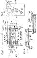
- Fig. 1 shows a winding machine 1 with a spool 2 respectively. 2.1 with each a sleeve 3 and a pack 4 on the sleeve 3 of the mandrel 2.
- the spindles 2 and 2.1 are part of a so-called known Turret spool changer, which for changing from a full pack 4 on an empty sleeve 3 about an axis of rotation 12, in a manner known per se is rotated so that a thread F to be wound without interrupting the Winding up from the full package 4 to the next empty tube 3 can be brought.
- the thread F is wound by a thread guide 10 in a manner known per se changed and by means of a contact roller 5 on an empty sleeve 3 or brought to a package 4 already started.
- the contact roller 5 can be rotated and driven in a contact roller housing 6 stored.
- the contact roller housing 6 is stationary on a drive housing 13 attached, in which also the axis of rotation 12 one for Turret spool changer belonging to mandrel carrier 11 rotates and is drivably mounted.
- the thread guide 10 is part of a traversing device 7, which on Guide rails 9 is mounted and either by means of a handle 8 by hand or by mechanical means (not shown) from the winder 1 is removable.
- FIGS. 4a.1 to 4b.2 shows a wing traversing unit 14 or 14.1 in cross section, which Is part of the traversing device 7. It points, depending on the number at the same time threads to be wound on a spool 2 or 2.1, the Traversing device 7 a corresponding number of traversing units 14 or 14.1 arranged next to each other, as shown with FIGS. 4a.1 to 4b.2 is.
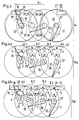
- traversing wings In the traversing unit 14; 14.1 of FIG. 2 are so-called traversing wings shown which, as can be seen from FIGS. 4 to 4b.2 or 5 to 5b.1, according to the transport of the thread in one direction or the other have different positions.
- FIG. 2 it is essentially each other Opposing wing pairs are, as is also the case with FIGS. 4 and 5 is shown, the individual wings are driven separately, as is the case with the Figures 4a.1 to 4b.1 and 5a.1 and 5b.1 is shown.
- the wings shown with solid lines correspond to Wings of the figures 4 to 4b.2 described below and those with solid and dash-dotted lines combine the wing shown Wings of the wings of Figures 5 to 5b.1 described later.
- the thread F corresponds to the Direction of a thread running from top to bottom, with a view of the figure seen, has.
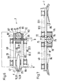
- FIG. 4 which an arrangement of traversing wings in Represents direction of view I (Fig. 2) in the CAD drawing style, so there is an upper one left (looking at the figure) outer wing with 15 and a lower left Outer wings marked with 16, while upper intermediate wings with 17 and 18 and lower intermediate wings are marked with 19 and 20.
- the specified number of wing pairs per stroke length H.1 and the length of the Wing, seen from its axis of rotation to the tip, is chosen so that for example lines of symmetry S, which by adjacent intersection of Circles of movement of the tips of the wings 15, 17, 18, 21 or 16, 19, 20, 22,
- the circles of movement designated with K.1, K.2 and K.3 pulled through the axes of rotation of the wings 17 or 19 and 18 or 20, Include angle ⁇ of essentially 45 degrees.
- the displacement of the upper outer wings 15 and 21 compared to the lower Outer wings 16 and 22 is also from the axes of rotation shown offset the outer wing is recognizable, with the axis of rotation of the upper left Outer wing 15 with 23 and the axis of rotation of the lower left outer wing 16 with 24, while the axis of rotation of the upper right outer wing 21 with 27 and the axis of rotation of the lower right outer wing 22 is identified by 28.
- the thread transfer to the outer wings is more precise shape, ramps 29 and 31 provided, the ramp 29 for the left Outer wing 15; 16 and the ramp 31 for the right outer wing 21; 22 is provided.
- the ramp 29 can be a stroke limiter 30 and the ramp 31 have a stroke limiter 32.
- stroke limiters are used for precise Position of the thread at the end of the traverse stroke, occasionally also simply a stroke called.
- Fig. 4a.1 there is also a thread ruler 47 with dash-dotted lines shown, this thread ruler 47 any predetermined contour can have and does not have to be rectilinear, but preferably rectilinear is.
- FIGS. 4a.1 to 4b.2 show, all of the upper wings and all of the lower wings are Wing of a traversing unit 14.a or 14.b each together by means of a Belt drive 33 or 33.1 driven.
- Figures 4a.1 and 4a.2 show the wings of the top row and the figures 4b.1 and 4b.2 the wings of the lower row. Accordingly, they are 4 to 4b also in FIGS. 4a.1 or 4a.2 and 4b1 or 4b.2 listed.
- 4a.1 and 4a.2 show three wing traversing units 14.a, one each Coil, arranged on a total base plate 49, here for example 3 Wing traversing units, but the number is not limited to these three is limited, but depending on the number of coils there is one unit per coil 14a provided.
- this is the base plate for the upper wings 15, 17, 18 and 21.
- FIG. 4a.1 is drawn in the style of a CAD drawing, that is, elements that are provided behind the front elements not with dashed lines, but also with solid lines shown.
- the way in which the elements are stacked is shown in Fig. 4a.2 shown.
- This figure shows the base plate 49 in viewing direction II (Fig.4a.1) and below, with a view of the figure, with dash-dotted lines Lines shown, the traversing units 14.a and the axes of rotation 23, 25, 26th and 27 of the vanes 15, 17, 18 and 21, which rotate about these axes of rotation (in this figure not shown) are rotatably mounted in the base plate 49.
- wing wing unit 14.a Belt drive 33 is provided, which the wings 15, 17, 18 and 21 on the Drives axes of rotation 23, 25, 26 and 27.
- an overdrive element is a Toothed belt 58 (teeth are not shown) is provided.
- the toothed belt 58 runs per traversing unit 14.a, as shown in FIG. 4a.1, via an overdrive roller 53 and drive rollers 56, each of which Roll per wing is provided, and via a guide roller 54 to the to give individual wings the corresponding direction of rotation.
- the axis of rotation 51 of the overdrive roller 53 is, as can be seen from FIG. 4a.2, shown longer than the axes of rotation 23, 25, 26 and 27, because the overdrive roller 53 is also correspondingly longer by a belt overdrive 34 which, as shown in Fig. 4a.1, in two wing traversing units 14.a is guided over a tension roller 52.
- the third axis of rotation 51 (seen from left to right on the figure) longer than that two preceding axes of rotation 51, namely in addition to Belt overdrive 34 still include a main belt drive 36, which further by a displaceable tensioning roller 48, a deflection roller 55 and around a motor pinion 35 is guided around.
- the upper overdrive roller 53 or 53.1 is also connected by means of a shaft 66 the lower overdrive roller 53.a (seen with a view of FIG. 2 or 3) connected so that the torque of the overdrive rollers 53 and 53.1 on the Overdrive rollers 53.a and thus on the belt drive 33.1 or 33.3 can be transferred.
- the wings 16, 19, 20 and 22 each have a drive roller 56 provided which a toothed belt 58.1 in the appropriate manner pick up the timing belt to the wings shown with the arrow Direction of rotation transmitted.
- the toothed belt 58.1 is further on Deflection pulley 54 and around the overdrive pulley 53a.
- the traversing device 7 can be pushed in means that the motor pinion 35 only engages in the main belt drive 36, when the chanching device 7 is inserted in its operating position.
- the belt guide runs such that, as shown with dashed lines, the tension roller 48 in the position shown by dashed lines is not to thereby inserted traversing device 7 the belt of the main belt drive 36 to keep excited.
- the axis of rotation of the deflection roller 55 is identified by 60.
- the axes of rotation the deflection rollers 54 and tension roller 48 are not shown. 2 is For the sake of simplicity, only the belt drive 33 or 33.1 or 33.2 or 33.3 shown.
- Figures 4b.1 and 4b.2 show the arrangement according to the invention lower wing, in which one wing wing unit 14.b one each Axis of rotation 51 pivotable unit base plate 50 is provided, what with arrows 62 and 62.a and 62.b is shown.
- the predetermined distance between the entire base plate 49 and individual unit base plates 50 is replaced by a spacer sleeve 61 ensured.
- This spacer sleeve 61 has a smaller diameter Bearing extension 64 on which the base plate 50 pivots to thereby, as shown in Fig. 3 and 4b.1, the base plates corresponding to the Swivel arrows 62 or 62.a or 62.b to pivot about the axis of rotation 51.
- the base plate 50 lies entirely on that in FIG. 3 and in FIG. 4b.2 spacer sleeve 61 shown cut off.
- each base plate 50 provided with one or two bevels 65, which at least one Correspond to a circular section with the swivel radius R, with the radius R extends from the axis of rotation 51 and half the width b of the base plate 50 corresponds.
- These bevels 65 of the individual base plates 50 hit accordingly at a connecting line 63 which the Axes of rotation 51 connects.
- the outermost base plate is turned clockwise on the right Arrow 62.b pivoted through 180 °.
- FIG. 4b.1 has a CAD system similar to that of FIG. 4a.1 Representation, that is, as already mentioned, for those elements, which are in Fig. 4b.1 behind the base plate 50, not dashed Lines, but solid lines were used. However, in order to Location of wings 16, 19, 20 and 22 and the drive of these wings clarity provide, is the effective position of the drive 33.1 and the wing in Fig. 4b.2 16, 19, 20 and 22 compared to the base plates 50.
- 5 to 5b.1 show that with a shortened stroke H.2 compared to a longer stroke H.1 of FIG. 4, instead of four pairs of wings, which rotate opposite each other, uses two pairs of wings can be compared, which, however, are specified as double wings the single wings of FIGS. 4 to 4b.2.
- FIG. 5 shows the mutual position of the upper and lower analog to FIG. 4 Wing, seen with a view of FIGS. 2 and 3.
- An upper left wing seen with a view of FIG. 5, is made up of the Wing halves 37 and 38 together, the right upper wing from the Wing halves 41 and 42, while the lower wing on the left emerges from the halves 39 and 40 and the lower wing on the right composed of halves 43 and 44.
- the upper wing is 37/38 about the axis of rotation 67
- the directions of rotation of the respective wings are one Direction of rotation arrow shown.
- FIG. 5a the position of the wing halves shown in FIG. 5a is this double wing, as shown, also chosen so that the earlier mentioned angle ⁇ under the conditions mentioned essentially is guaranteed. A corresponding explanation is therefore unnecessary in this regard for FIGS. 5 to 5b.1.
- FIG. 5a in this regard also applies to FIG. 5b.
- FIGS. 4a and 4b which is why only in FIGS. 4 and 4a the angle ⁇ is shown.
- FIG. 5 shows, as already mentioned, the upper and lower wing pairs, while Fig. 5a only the upper wings 37/38 and 41/42 and Fig 5b only represents the lower wings 39/40 and 43/44.
- Fig. 5 the whole is made up of the upper and lower wings Composing traversing unit with 14.1, while in Fig. 5a the upper Wing of the traversing unit with 14.1a and the lower wing in Fig. 5b Traversing unit are marked with 14.1b.
- 5a and 5b are the thread ruler 47 and in FIG. 5b ramps 29 and 31 are also shown.
- Figures 5a.1 and 5b.1 represent in an analogous manner to Figs. 4a.1 and 4b.1 a total base plate 49.1 (Fig.5a.1) and a unit base plate 50.1 (Fig.5b.1), which is to show that the pivoting of the base plates 50.1 in the same way as for the base plates 50 and that also happens Connection and the drives work in the same way as for Fig. 4a.1 to 4b.2, which is why these details are not repeated for FIGS. 5a.1 and 5b.1 will.
- elements with analog functions are also compatible with the provided analog reference numerals.
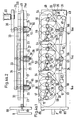
- FIGS. 6 to 8 show a variant compared to FIGS. 2, 3 and 4a.1 to 4b.2, as the drive of the overdrive roller 53 or 53.1 and 53a not by means of the belt overdrive 34, but by means of a drive shaft 76 is carried out, which their torque via a drive pinion 75 to the in Fig. 6 and 7 shown overdrive gears 73 and 74 transmits which in turn drive the overdrive rollers 53 via a connecting shaft 81.
- the shaft 76 has a coupling half 78, which in connection with a Coupling half 79 of a drive motor 80 non-positively connected can be brought when the traversing device in the operating position is inserted.
- the drive motor 80 is stationary in the same way as the drive motor 59 Drive housing 13 provided.
- the overdrive gears 73 and 74 and the drive pinion 75 have one matching helical or spiral teeth.
- the base plate 49 has hinge and bearing extensions 71, in which the shaft 76 is rotatably supported and as a left axial stop with As seen in Figure 8, serves for the position of the drive pinion 75.
- the lower base plate 50.2 is the Figures 4a.1 to 4b.2 and Figures 5a.1 and 5b.1 in an analogous manner
- slot nuts 77 are provided in each case.
- hinge and bearing extensions 71 and 72 For assembly and disassembly of hinge and bearing extensions 71 and 72 together Shaft 76 and drive pinion 75 are the hinge and bearing extensions 71 and 72 each fastened to the base plate 49 or 50.2 with connecting screws 82.
- Supports 86 serve as legs on which the traversing device 7 on the Rails 9 in the operating position on a handle belonging to a front plate 88 8 can be inserted.
- the traversing units 14 to 14.1b are in a housing 87 housed.
Landscapes
- Engineering & Computer Science (AREA)
- Textile Engineering (AREA)
- Replacing, Conveying, And Pick-Finding For Filamentary Materials (AREA)
- Winding Filamentary Materials (AREA)
- Replacement Of Web Rolls (AREA)
Claims (16)
- Arrangement de va-et-vient à aillettes (7) pour le guidage d'un fil en va-et-vient le long d'un mandrin de bobine d'un bobinoir, afin de former une bobine sur celui-ci,
avec deux plaques de base (49,50,50.1,50.2) disposées en opposition l'une par rapport à l'autre,
entre lesquelles, des ailettes de va-et-vient (15-22 et 37-44) sont disposées d'une manière rotative et commandable, et où les ailettes sont disposées immédiatement les unes en face des autres, et un entraínement commun est prévu pour les ailettes,
caractérisé par le fait
qu'une rangée d'ailettes (15,17,18,21; 37,38,41,42) est adjointe à l'une des plaques de base (49), et l'autre rangée d'ailettes (16,19,20,22; 39,40,43,44), disposée en face, est adjointe à l'autre plaque de base (50,50.1,50.2), et que l'une des plaques de base (50,50.1,50.2) peut être déplacée dans une position de repos, éloignée de l'autre plaque de base (49). - Arrangement de va-et-vient selon revendication 1,
caractérisé par le fait que,
pour un renvidage de plusieurs fils par mandrin de bobine (2,3), l'arrangement de va-et-vient est prévu avec plusieurs unités de va-et-vient (14), en correspondance. - Arrangement de va-et-vient selon revendication 2,
caractérisé par le fait que
la plaque de base (50), pouvant être déplacée, est subdivisée selon le nombre d'unités de va-et-vient (50.1,50.2), et chaque unité peut être déplacée individuellement dans une position de repos éloignée. - Arrangement de va-et-vient selon revendication 1 ou 3,
caractérisé par le fait que
la plaque de base (50,50.1,50.2), pouvant être déplacée, est disposée d'une manière pivotable. - Arrangement de va-et-vient selon revendication 4,
caractérisé par le fait que
la plaque de base (50,50.1,50.2), pouvant être déplacée, est disposée d'une manière pivotable autour d'un axe de pivotement (51,76), lequel est en même temps axe de rotation (51,76) pour un arbre (53,76) entraínant les ailettes (16,19,20,22; 39,40, 43,44). - Arrangement de va-et-vient selon revendication 1,
caractérisé par le fait
qu'une commande commune (33-36; 73-76) est prévue pour les ailettes. - Arrangement de va-et-vient selon revendication 6,
caractérisé par le fait que
la plaque de base (50,50.1,50.2), pouvant être déplacée, est déplaçable tout en maintenant la liaison des ailettes avec l'entraínement commun. - Arrangement de va-et-vient selon revendication 1,
caractérisé par le fait que
les ailettes d'une unité de va-et-vient sont disposées de telle sorte que, dans une position de l'ailette, dans laquelle celle-ci réceptionne le fil, et dans la position suivante, dans laquelle l'ailette délivre le fil, la ligne de symétrie d'une ailette comprend un angle α ayant essentiellement 45°. - Arrangement de va-et-vient selon revendication 1,
caractérisé par le fait que,
dans une unité de va-et-vient à ailettes, au moins deux paires d'ailettes avec des ailettes disposées essentiellement les unes en face des autres, sont prévues par course (H.1,H.2), et où les axes de rotation des paires d'ailettes, provoquant l'inversion de la course du fil, sont disposés d'une manière décalée l'un par rapport à l'autre, de telle sorte que l'ailette de réception de fil s'avance plus loin vers le fil et plus loin dans le sens de la course, que l'ailette délivrant le fil. - Arrangement de va-et-vient selon revendication 1,
caractérisé par le fait que,
vu dans le sens déplacement du fil, des ailettes extérieures supérieures (15,21; 37,42) sont décalées par rapport aux ailettes extérieures inférieures (16,22; 39,44), de telle sorte que les pointes des ailettes extérieures supérieures (15,21; 37,42), dirigeant le fil (F) dans la course (H.1,H.2) s'avancent plus loin vers le fil (F) que les pointes des ailettes extérieures inférieures (16,22; 39,44), dirigeant le fil (F) vers le bord de la course (H.1,H.2). - Arrangement de va-et-vient selon revendication 1,
caractérisé par le fait que,
vu dans le sens de déplacement du fil (F), la transmission du fil s'effectue au bord d'une course (H.1,H.2), depuis une ailette extérieure inférieure (16,22; 39,44) vers une ailette extérieure supérieure (15,21; 37,42). - Arrangement de va-et-vient selon revendication 1,
caractérisé par le fait que
les ailettes d'une unité de va-et-vient à ailettes peuvent être entraínées par une commande à courroies crantées (33-36) ou une transmission par pignons (73-76). - Arrangement de va-et-vient selon revendication 12,
caractérisé par le fait que
la transmission et le moteur (59,80) entraínant la transmission sont disposés l'un par rapport à l'autre de telle sorte que le moteur n'est accouplé à la transmission qu'après l'insertion complète de l'unité de va-et-vient. - Arrangement de va-et-vient selon revendication 13,
caractérisé par le fait que
le moteur (59,80) est disposé d'une manière stationnaire. - Arrangement de va-et-vient selon revendication 9,
caractérisé par le fait
qu'une rampe (29,31) est prévue en plus, dans les deux zones de fin de course, avec une butée (30,32), afin de préciser la transmission du fil. - Arrangement de va-et-vient selon au moins une des revendication précédentes, dans un bobinoir, utilisé pour renvider au moins un fil textile (F), particulièrement un fil de filaments synthétiques sans fin, avec un élément de soutien (9) pour un module de va-et-vient échangeable,
caractérisé par le fait que
l'arrangement de va-et-vient peut être inséré dans le bobinoir sur l'élément de soutien.
Applications Claiming Priority (2)
| Application Number | Priority Date | Filing Date | Title |
|---|---|---|---|
| CH1300/93 | 1993-04-29 | ||
| CH130093 | 1993-04-29 |
Publications (2)
| Publication Number | Publication Date |
|---|---|
| EP0622324A1 EP0622324A1 (fr) | 1994-11-02 |
| EP0622324B1 true EP0622324B1 (fr) | 1998-01-14 |
Family
ID=4207217
Family Applications (1)
| Application Number | Title | Priority Date | Filing Date |
|---|---|---|---|
| EP94810216A Expired - Lifetime EP0622324B1 (fr) | 1993-04-29 | 1994-04-18 | Dispositif de va-et-vient avec des ailes |
Country Status (4)
| Country | Link |
|---|---|
| US (1) | US5607115A (fr) |
| EP (1) | EP0622324B1 (fr) |
| JP (1) | JPH06329334A (fr) |
| DE (1) | DE59404991D1 (fr) |
Cited By (2)
| Publication number | Priority date | Publication date | Assignee | Title |
|---|---|---|---|---|
| CN107257769A (zh) * | 2014-12-02 | 2017-10-17 | 迪策&谢尔机械两合公司 | 卷绕材料引导装置 |
| DE102023000737A1 (de) | 2023-03-01 | 2024-09-05 | Oerlikon Textile Gmbh & Co. Kg | Changiereinrichtung und Aufspulvorrichtung zum Aufspulen mehrerer synthetischer Fäden mit einer Changiereinrichtung |
Families Citing this family (4)
| Publication number | Priority date | Publication date | Assignee | Title |
|---|---|---|---|---|
| JPH11100166A (ja) * | 1997-09-29 | 1999-04-13 | Murata Mach Ltd | 紡糸巻取機 |
| TW387855B (en) * | 1998-06-25 | 2000-04-21 | Murata Machinery Ltd | Reciprocating device on blades |
| CN102491124B (zh) * | 2011-11-16 | 2013-08-21 | 安徽宁国市先浩高温材料有限公司 | 一种高精度整形绕线机 |
| DE102013000447A1 (de) | 2013-01-12 | 2014-07-17 | Oerlikon Textile Gmbh & Co. Kg | Aufspulmaschine |
Family Cites Families (11)
| Publication number | Priority date | Publication date | Assignee | Title |
|---|---|---|---|---|
| DE212240C (fr) * | ||||
| GB1131884A (en) * | 1966-05-30 | 1968-10-30 | Chatillon Italiana Fibre | Device for winding yarn and thread |
| CH511182A (de) * | 1970-06-10 | 1971-08-15 | Toray Industries | Verfahren zur Bildung einer Querbewegung des Garnes beim Spulen sowie Vorrichtung zur Ausführung des Verfahrens |
| CH571446A5 (fr) * | 1972-11-11 | 1976-01-15 | Schuster & Co F M N | |
| JPS5948357A (ja) * | 1982-09-08 | 1984-03-19 | Toray Ind Inc | 糸条巻取方法およびその装置 |
| DE3772173D1 (de) * | 1986-12-02 | 1991-09-19 | Rieter Ag Maschf | Changiereinrichtung. |
| CH673997A5 (fr) * | 1987-10-17 | 1990-04-30 | Schaerer Ag | |
| US4991783A (en) * | 1987-12-30 | 1991-02-12 | Teijin Seiki Co., Ltd. | Yarn traversing method and an apparatus therefor |
| JP2627658B2 (ja) * | 1989-02-04 | 1997-07-09 | 帝人製機株式会社 | 糸条のトラバース装置 |
| US5282582A (en) * | 1989-04-28 | 1994-02-01 | Teijin Seiki Co., Ltd. | Yarn traversing apparatus |
| EP0521816B1 (fr) * | 1991-07-04 | 1996-03-13 | Maschinenfabrik Rieter Ag | Procédé pour transferer le fil d'une bobine pleine à une bobine vide et un bobinoir |
-
1994
- 1994-04-18 EP EP94810216A patent/EP0622324B1/fr not_active Expired - Lifetime
- 1994-04-18 DE DE59404991T patent/DE59404991D1/de not_active Expired - Fee Related
- 1994-04-28 JP JP6091777A patent/JPH06329334A/ja active Pending
- 1994-04-29 US US08/235,528 patent/US5607115A/en not_active Expired - Fee Related
Cited By (3)
| Publication number | Priority date | Publication date | Assignee | Title |
|---|---|---|---|---|
| CN107257769A (zh) * | 2014-12-02 | 2017-10-17 | 迪策&谢尔机械两合公司 | 卷绕材料引导装置 |
| CN107257769B (zh) * | 2014-12-02 | 2018-10-02 | 迪策&谢尔机械两合公司 | 卷绕材料引导装置 |
| DE102023000737A1 (de) | 2023-03-01 | 2024-09-05 | Oerlikon Textile Gmbh & Co. Kg | Changiereinrichtung und Aufspulvorrichtung zum Aufspulen mehrerer synthetischer Fäden mit einer Changiereinrichtung |
Also Published As
| Publication number | Publication date |
|---|---|
| JPH06329334A (ja) | 1994-11-29 |
| EP0622324A1 (fr) | 1994-11-02 |
| DE59404991D1 (de) | 1998-02-19 |
| US5607115A (en) | 1997-03-04 |
Similar Documents
| Publication | Publication Date | Title |
|---|---|---|
| DE3414721C2 (de) | Vorrichtung zum Reinigen von Rohren | |
| DE2343994C2 (de) | Fadenspeicher- und -liefervorrichtung | |
| DE2744935C2 (de) | Spulenantriebsvorrichtungen für Rundflechtmaschinen | |
| DE7016570U (de) | Verstellbares galettenabzugswerk. | |
| DE3417890C2 (de) | Biegemaschine für draht- oder bandförmiges Material | |
| EP0744480B1 (fr) | Dispositif de fausse torsion | |
| EP0622324B1 (fr) | Dispositif de va-et-vient avec des ailes | |
| EP0063690B1 (fr) | Dispositif pour le bobinage d'un fil | |
| CH669372A5 (fr) | ||
| DE2243054A1 (de) | Rundstrickmaschine | |
| DE1510339B2 (de) | Vorrichtung zum Ablegen von Faserlunten in stillstehende Kannen | |
| DE69718364T2 (de) | Fadentraversiervorrichtung | |
| EP0740712B1 (fr) | Procede et dispositif permettant d'imprimer alternativement une torsion en "s" ou en "z" a un fil | |
| DE3732575C1 (en) | Traversing device on winding appliances for threads, tapes or the like with a variable thread-guide stroke | |
| EP0114641B1 (fr) | Machine à bobiner avec guide-fil à pales | |
| DE2317094A1 (de) | Maschine zur herstellung von wulstkernen fuer luftreifenwuelste | |
| DE3131986A1 (de) | Druckgasspleissvorrichtung fuer textilfaeden | |
| DE8806229U1 (de) | Flechtmaschine | |
| DE10236337B3 (de) | Vorspul-Gerät | |
| DE1560605B1 (de) | Vorrichtung zum Vorbereiten von Ablaufspulen fuer automatische Spulmaschinen | |
| DE4311425A1 (de) | Vorrichtung zur Zuführung elastomerer Fäden | |
| CH687711A5 (de) | Flyer mit fest angeordneter Spulenbank. | |
| DE830346C (de) | Selbsttaetige Farbbandumkehrvorrichtung | |
| DE2902023C2 (de) | Fadenliefervorrichtung für Strickmaschinen | |
| DE1610385C (de) | Verfahren und Vorrichtung zur gleich zeitigen Herstellung zweier im Eingriff befindlicher Kuppelgliederreihen für Schraubenfederreißverschlüsse |
Legal Events
| Date | Code | Title | Description |
|---|---|---|---|
| PUAI | Public reference made under article 153(3) epc to a published international application that has entered the european phase |
Free format text: ORIGINAL CODE: 0009012 |
|
| 17P | Request for examination filed |
Effective date: 19940818 |
|
| AK | Designated contracting states |
Kind code of ref document: A1 Designated state(s): CH DE FR GB IT LI |
|
| 17Q | First examination report despatched |
Effective date: 19951129 |
|
| GRAG | Despatch of communication of intention to grant |
Free format text: ORIGINAL CODE: EPIDOS AGRA |
|
| GRAG | Despatch of communication of intention to grant |
Free format text: ORIGINAL CODE: EPIDOS AGRA |
|
| GRAH | Despatch of communication of intention to grant a patent |
Free format text: ORIGINAL CODE: EPIDOS IGRA |
|
| GRAH | Despatch of communication of intention to grant a patent |
Free format text: ORIGINAL CODE: EPIDOS IGRA |
|
| GRAA | (expected) grant |
Free format text: ORIGINAL CODE: 0009210 |
|
| AK | Designated contracting states |
Kind code of ref document: B1 Designated state(s): CH DE FR GB IT LI |
|
| PG25 | Lapsed in a contracting state [announced via postgrant information from national office to epo] |
Ref country code: GB Free format text: LAPSE BECAUSE OF FAILURE TO SUBMIT A TRANSLATION OF THE DESCRIPTION OR TO PAY THE FEE WITHIN THE PRESCRIBED TIME-LIMIT Effective date: 19980114 Ref country code: FR Free format text: LAPSE BECAUSE OF FAILURE TO SUBMIT A TRANSLATION OF THE DESCRIPTION OR TO PAY THE FEE WITHIN THE PRESCRIBED TIME-LIMIT Effective date: 19980114 |
|
| REG | Reference to a national code |
Ref country code: CH Ref legal event code: EP |
|
| REF | Corresponds to: |
Ref document number: 59404991 Country of ref document: DE Date of ref document: 19980219 |
|
| ITF | It: translation for a ep patent filed | ||
| PGFP | Annual fee paid to national office [announced via postgrant information from national office to epo] |
Ref country code: DE Payment date: 19980326 Year of fee payment: 5 |
|
| PGFP | Annual fee paid to national office [announced via postgrant information from national office to epo] |
Ref country code: CH Payment date: 19980403 Year of fee payment: 5 |
|
| EN | Fr: translation not filed | ||
| GBV | Gb: ep patent (uk) treated as always having been void in accordance with gb section 77(7)/1977 [no translation filed] |
Effective date: 19980114 |
|
| PLBE | No opposition filed within time limit |
Free format text: ORIGINAL CODE: 0009261 |
|
| STAA | Information on the status of an ep patent application or granted ep patent |
Free format text: STATUS: NO OPPOSITION FILED WITHIN TIME LIMIT |
|
| 26N | No opposition filed | ||
| PG25 | Lapsed in a contracting state [announced via postgrant information from national office to epo] |
Ref country code: LI Free format text: LAPSE BECAUSE OF NON-PAYMENT OF DUE FEES Effective date: 19990430 Ref country code: CH Free format text: LAPSE BECAUSE OF NON-PAYMENT OF DUE FEES Effective date: 19990430 |
|
| REG | Reference to a national code |
Ref country code: CH Ref legal event code: PL |
|
| PG25 | Lapsed in a contracting state [announced via postgrant information from national office to epo] |
Ref country code: DE Free format text: LAPSE BECAUSE OF NON-PAYMENT OF DUE FEES Effective date: 20000201 |
|
| PG25 | Lapsed in a contracting state [announced via postgrant information from national office to epo] |
Ref country code: IT Free format text: LAPSE BECAUSE OF NON-PAYMENT OF DUE FEES Effective date: 20050418 |