EP0622324B1 - Yarn traversing device with wings - Google Patents
Yarn traversing device with wings Download PDFInfo
- Publication number
- EP0622324B1 EP0622324B1 EP94810216A EP94810216A EP0622324B1 EP 0622324 B1 EP0622324 B1 EP 0622324B1 EP 94810216 A EP94810216 A EP 94810216A EP 94810216 A EP94810216 A EP 94810216A EP 0622324 B1 EP0622324 B1 EP 0622324B1
- Authority
- EP
- European Patent Office
- Prior art keywords
- wings
- traversing
- yarn
- traversing device
- base plate
- Prior art date
- Legal status (The legal status is an assumption and is not a legal conclusion. Google has not performed a legal analysis and makes no representation as to the accuracy of the status listed.)
- Expired - Lifetime
Links
Images


Classifications
-
- B—PERFORMING OPERATIONS; TRANSPORTING
- B65—CONVEYING; PACKING; STORING; HANDLING THIN OR FILAMENTARY MATERIAL
- B65H—HANDLING THIN OR FILAMENTARY MATERIAL, e.g. SHEETS, WEBS, CABLES
- B65H54/00—Winding, coiling, or depositing filamentary material
- B65H54/02—Winding and traversing material on to reels, bobbins, tubes, or like package cores or formers
- B65H54/28—Traversing devices; Package-shaping arrangements
- B65H54/2836—Traversing devices; Package-shaping arrangements with a rotating guide for traversing the yarn
- B65H54/2839—Traversing devices; Package-shaping arrangements with a rotating guide for traversing the yarn counter rotating guides, e.g. wings
-
- B—PERFORMING OPERATIONS; TRANSPORTING
- B65—CONVEYING; PACKING; STORING; HANDLING THIN OR FILAMENTARY MATERIAL
- B65H—HANDLING THIN OR FILAMENTARY MATERIAL, e.g. SHEETS, WEBS, CABLES
- B65H54/00—Winding, coiling, or depositing filamentary material
- B65H54/70—Other constructional features of yarn-winding machines
- B65H54/72—Framework; Casings; Coverings
-
- B—PERFORMING OPERATIONS; TRANSPORTING
- B65—CONVEYING; PACKING; STORING; HANDLING THIN OR FILAMENTARY MATERIAL
- B65H—HANDLING THIN OR FILAMENTARY MATERIAL, e.g. SHEETS, WEBS, CABLES
- B65H2301/00—Handling processes for sheets or webs
- B65H2301/50—Auxiliary process performed during handling process
- B65H2301/53—Auxiliary process performed during handling process for acting on performance of handling machine
- B65H2301/531—Cleaning parts of handling machine
-
- B—PERFORMING OPERATIONS; TRANSPORTING
- B65—CONVEYING; PACKING; STORING; HANDLING THIN OR FILAMENTARY MATERIAL
- B65H—HANDLING THIN OR FILAMENTARY MATERIAL, e.g. SHEETS, WEBS, CABLES
- B65H2601/00—Problem to be solved or advantage achieved
- B65H2601/30—Facilitating or easing
- B65H2601/32—Facilitating or easing entities relating to handling machine
- B65H2601/321—Access
-
- B—PERFORMING OPERATIONS; TRANSPORTING
- B65—CONVEYING; PACKING; STORING; HANDLING THIN OR FILAMENTARY MATERIAL
- B65H—HANDLING THIN OR FILAMENTARY MATERIAL, e.g. SHEETS, WEBS, CABLES
- B65H2701/00—Handled material; Storage means
- B65H2701/30—Handled filamentary material
- B65H2701/31—Textiles threads or artificial strands of filaments
Definitions
- the invention relates to a wing traversing device for back and forth a thread along a bobbin mandrel in a bobbin winder to a bobbin to form on it, with two base plates arranged opposite one another between which traversing wings are rotatably and drivably arranged.
- Such a device is for example from the German Publication No. 17 10 068 and from the European patent application No. 0 322 752A1 and from U.S. Patent No. 4,674,694. These spinning machines have a single spool.
- the European patent application shows with the Publication number 0 272 458 A1 also by the same applicant Winding machine with two spindles, in which the traversing device interchangeable traversing module, which is on one in the machine provided support element rests.
- the traversing device comprises one Groove drum with a thread guide in the groove, for the purpose Traversing the thread, while the first two patents have so-called wing traversing devices to the thread in the both traversing directions, for the purpose of building a coil package transport.
- Grooved drum changings and wing changings each have their own Areas of application and are provided depending on the intended use.
- the solution according to the invention is that the one wing of the one Base plate and the other, opposite wings of the others Base plate are assigned and that the one base plate in one of the other base plate distant rest position is displaceable.
- a particularly advantageous embodiment has claim 16 with a Traversing device according to at least one of the preceding claims in a winding machine for winding at least one textile thread, in particular a thread made of synthetic continuous filaments, with a Support element for an exchangeable traversing module, characterized in that that the traversing device on the support element in the winding machine can be inserted.
- the advantages of the invention are, on the one hand, that for everyone Areas of application only a winding machine is required, in which the According to requirements either one, for example in EP-0 272 458 A1 published traversing device with grooved drum, or a The traversing device described below with wings in the winding machine can be inserted and on the other hand in the possibility of the wings of the Wing swinging without separating the traversing units from its drive easy to clean or replace.
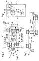
- Fig. 1 shows a winding machine 1 with a spool 2 respectively. 2.1 with each a sleeve 3 and a pack 4 on the sleeve 3 of the mandrel 2.
- the spindles 2 and 2.1 are part of a so-called known Turret spool changer, which for changing from a full pack 4 on an empty sleeve 3 about an axis of rotation 12, in a manner known per se is rotated so that a thread F to be wound without interrupting the Winding up from the full package 4 to the next empty tube 3 can be brought.
- the thread F is wound by a thread guide 10 in a manner known per se changed and by means of a contact roller 5 on an empty sleeve 3 or brought to a package 4 already started.
- the contact roller 5 can be rotated and driven in a contact roller housing 6 stored.
- the contact roller housing 6 is stationary on a drive housing 13 attached, in which also the axis of rotation 12 one for Turret spool changer belonging to mandrel carrier 11 rotates and is drivably mounted.
- the thread guide 10 is part of a traversing device 7, which on Guide rails 9 is mounted and either by means of a handle 8 by hand or by mechanical means (not shown) from the winder 1 is removable.
- FIGS. 4a.1 to 4b.2 shows a wing traversing unit 14 or 14.1 in cross section, which Is part of the traversing device 7. It points, depending on the number at the same time threads to be wound on a spool 2 or 2.1, the Traversing device 7 a corresponding number of traversing units 14 or 14.1 arranged next to each other, as shown with FIGS. 4a.1 to 4b.2 is.
- traversing wings In the traversing unit 14; 14.1 of FIG. 2 are so-called traversing wings shown which, as can be seen from FIGS. 4 to 4b.2 or 5 to 5b.1, according to the transport of the thread in one direction or the other have different positions.
- FIG. 2 it is essentially each other Opposing wing pairs are, as is also the case with FIGS. 4 and 5 is shown, the individual wings are driven separately, as is the case with the Figures 4a.1 to 4b.1 and 5a.1 and 5b.1 is shown.
- the wings shown with solid lines correspond to Wings of the figures 4 to 4b.2 described below and those with solid and dash-dotted lines combine the wing shown Wings of the wings of Figures 5 to 5b.1 described later.
- the thread F corresponds to the Direction of a thread running from top to bottom, with a view of the figure seen, has.
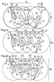
- FIG. 4 which an arrangement of traversing wings in Represents direction of view I (Fig. 2) in the CAD drawing style, so there is an upper one left (looking at the figure) outer wing with 15 and a lower left Outer wings marked with 16, while upper intermediate wings with 17 and 18 and lower intermediate wings are marked with 19 and 20.
- the specified number of wing pairs per stroke length H.1 and the length of the Wing, seen from its axis of rotation to the tip, is chosen so that for example lines of symmetry S, which by adjacent intersection of Circles of movement of the tips of the wings 15, 17, 18, 21 or 16, 19, 20, 22,
- the circles of movement designated with K.1, K.2 and K.3 pulled through the axes of rotation of the wings 17 or 19 and 18 or 20, Include angle ⁇ of essentially 45 degrees.
- the displacement of the upper outer wings 15 and 21 compared to the lower Outer wings 16 and 22 is also from the axes of rotation shown offset the outer wing is recognizable, with the axis of rotation of the upper left Outer wing 15 with 23 and the axis of rotation of the lower left outer wing 16 with 24, while the axis of rotation of the upper right outer wing 21 with 27 and the axis of rotation of the lower right outer wing 22 is identified by 28.
- the thread transfer to the outer wings is more precise shape, ramps 29 and 31 provided, the ramp 29 for the left Outer wing 15; 16 and the ramp 31 for the right outer wing 21; 22 is provided.
- the ramp 29 can be a stroke limiter 30 and the ramp 31 have a stroke limiter 32.
- stroke limiters are used for precise Position of the thread at the end of the traverse stroke, occasionally also simply a stroke called.
- Fig. 4a.1 there is also a thread ruler 47 with dash-dotted lines shown, this thread ruler 47 any predetermined contour can have and does not have to be rectilinear, but preferably rectilinear is.
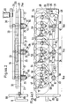
- FIGS. 4a.1 to 4b.2 show, all of the upper wings and all of the lower wings are Wing of a traversing unit 14.a or 14.b each together by means of a Belt drive 33 or 33.1 driven.
- Figures 4a.1 and 4a.2 show the wings of the top row and the figures 4b.1 and 4b.2 the wings of the lower row. Accordingly, they are 4 to 4b also in FIGS. 4a.1 or 4a.2 and 4b1 or 4b.2 listed.
- 4a.1 and 4a.2 show three wing traversing units 14.a, one each Coil, arranged on a total base plate 49, here for example 3 Wing traversing units, but the number is not limited to these three is limited, but depending on the number of coils there is one unit per coil 14a provided.
- this is the base plate for the upper wings 15, 17, 18 and 21.
- FIG. 4a.1 is drawn in the style of a CAD drawing, that is, elements that are provided behind the front elements not with dashed lines, but also with solid lines shown.
- the way in which the elements are stacked is shown in Fig. 4a.2 shown.
- This figure shows the base plate 49 in viewing direction II (Fig.4a.1) and below, with a view of the figure, with dash-dotted lines Lines shown, the traversing units 14.a and the axes of rotation 23, 25, 26th and 27 of the vanes 15, 17, 18 and 21, which rotate about these axes of rotation (in this figure not shown) are rotatably mounted in the base plate 49.
- wing wing unit 14.a Belt drive 33 is provided, which the wings 15, 17, 18 and 21 on the Drives axes of rotation 23, 25, 26 and 27.
- an overdrive element is a Toothed belt 58 (teeth are not shown) is provided.
- the toothed belt 58 runs per traversing unit 14.a, as shown in FIG. 4a.1, via an overdrive roller 53 and drive rollers 56, each of which Roll per wing is provided, and via a guide roller 54 to the to give individual wings the corresponding direction of rotation.
- the axis of rotation 51 of the overdrive roller 53 is, as can be seen from FIG. 4a.2, shown longer than the axes of rotation 23, 25, 26 and 27, because the overdrive roller 53 is also correspondingly longer by a belt overdrive 34 which, as shown in Fig. 4a.1, in two wing traversing units 14.a is guided over a tension roller 52.
- the third axis of rotation 51 (seen from left to right on the figure) longer than that two preceding axes of rotation 51, namely in addition to Belt overdrive 34 still include a main belt drive 36, which further by a displaceable tensioning roller 48, a deflection roller 55 and around a motor pinion 35 is guided around.
- the upper overdrive roller 53 or 53.1 is also connected by means of a shaft 66 the lower overdrive roller 53.a (seen with a view of FIG. 2 or 3) connected so that the torque of the overdrive rollers 53 and 53.1 on the Overdrive rollers 53.a and thus on the belt drive 33.1 or 33.3 can be transferred.
- the wings 16, 19, 20 and 22 each have a drive roller 56 provided which a toothed belt 58.1 in the appropriate manner pick up the timing belt to the wings shown with the arrow Direction of rotation transmitted.
- the toothed belt 58.1 is further on Deflection pulley 54 and around the overdrive pulley 53a.
- the traversing device 7 can be pushed in means that the motor pinion 35 only engages in the main belt drive 36, when the chanching device 7 is inserted in its operating position.
- the belt guide runs such that, as shown with dashed lines, the tension roller 48 in the position shown by dashed lines is not to thereby inserted traversing device 7 the belt of the main belt drive 36 to keep excited.
- the axis of rotation of the deflection roller 55 is identified by 60.
- the axes of rotation the deflection rollers 54 and tension roller 48 are not shown. 2 is For the sake of simplicity, only the belt drive 33 or 33.1 or 33.2 or 33.3 shown.
- Figures 4b.1 and 4b.2 show the arrangement according to the invention lower wing, in which one wing wing unit 14.b one each Axis of rotation 51 pivotable unit base plate 50 is provided, what with arrows 62 and 62.a and 62.b is shown.
- the predetermined distance between the entire base plate 49 and individual unit base plates 50 is replaced by a spacer sleeve 61 ensured.
- This spacer sleeve 61 has a smaller diameter Bearing extension 64 on which the base plate 50 pivots to thereby, as shown in Fig. 3 and 4b.1, the base plates corresponding to the Swivel arrows 62 or 62.a or 62.b to pivot about the axis of rotation 51.
- the base plate 50 lies entirely on that in FIG. 3 and in FIG. 4b.2 spacer sleeve 61 shown cut off.
- each base plate 50 provided with one or two bevels 65, which at least one Correspond to a circular section with the swivel radius R, with the radius R extends from the axis of rotation 51 and half the width b of the base plate 50 corresponds.
- These bevels 65 of the individual base plates 50 hit accordingly at a connecting line 63 which the Axes of rotation 51 connects.
- the outermost base plate is turned clockwise on the right Arrow 62.b pivoted through 180 °.
- FIG. 4b.1 has a CAD system similar to that of FIG. 4a.1 Representation, that is, as already mentioned, for those elements, which are in Fig. 4b.1 behind the base plate 50, not dashed Lines, but solid lines were used. However, in order to Location of wings 16, 19, 20 and 22 and the drive of these wings clarity provide, is the effective position of the drive 33.1 and the wing in Fig. 4b.2 16, 19, 20 and 22 compared to the base plates 50.
- 5 to 5b.1 show that with a shortened stroke H.2 compared to a longer stroke H.1 of FIG. 4, instead of four pairs of wings, which rotate opposite each other, uses two pairs of wings can be compared, which, however, are specified as double wings the single wings of FIGS. 4 to 4b.2.
- FIG. 5 shows the mutual position of the upper and lower analog to FIG. 4 Wing, seen with a view of FIGS. 2 and 3.
- An upper left wing seen with a view of FIG. 5, is made up of the Wing halves 37 and 38 together, the right upper wing from the Wing halves 41 and 42, while the lower wing on the left emerges from the halves 39 and 40 and the lower wing on the right composed of halves 43 and 44.
- the upper wing is 37/38 about the axis of rotation 67
- the directions of rotation of the respective wings are one Direction of rotation arrow shown.
- FIG. 5a the position of the wing halves shown in FIG. 5a is this double wing, as shown, also chosen so that the earlier mentioned angle ⁇ under the conditions mentioned essentially is guaranteed. A corresponding explanation is therefore unnecessary in this regard for FIGS. 5 to 5b.1.
- FIG. 5a in this regard also applies to FIG. 5b.
- FIGS. 4a and 4b which is why only in FIGS. 4 and 4a the angle ⁇ is shown.
- FIG. 5 shows, as already mentioned, the upper and lower wing pairs, while Fig. 5a only the upper wings 37/38 and 41/42 and Fig 5b only represents the lower wings 39/40 and 43/44.
- Fig. 5 the whole is made up of the upper and lower wings Composing traversing unit with 14.1, while in Fig. 5a the upper Wing of the traversing unit with 14.1a and the lower wing in Fig. 5b Traversing unit are marked with 14.1b.
- 5a and 5b are the thread ruler 47 and in FIG. 5b ramps 29 and 31 are also shown.
- Figures 5a.1 and 5b.1 represent in an analogous manner to Figs. 4a.1 and 4b.1 a total base plate 49.1 (Fig.5a.1) and a unit base plate 50.1 (Fig.5b.1), which is to show that the pivoting of the base plates 50.1 in the same way as for the base plates 50 and that also happens Connection and the drives work in the same way as for Fig. 4a.1 to 4b.2, which is why these details are not repeated for FIGS. 5a.1 and 5b.1 will.
- elements with analog functions are also compatible with the provided analog reference numerals.
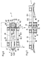
- FIGS. 6 to 8 show a variant compared to FIGS. 2, 3 and 4a.1 to 4b.2, as the drive of the overdrive roller 53 or 53.1 and 53a not by means of the belt overdrive 34, but by means of a drive shaft 76 is carried out, which their torque via a drive pinion 75 to the in Fig. 6 and 7 shown overdrive gears 73 and 74 transmits which in turn drive the overdrive rollers 53 via a connecting shaft 81.
- the shaft 76 has a coupling half 78, which in connection with a Coupling half 79 of a drive motor 80 non-positively connected can be brought when the traversing device in the operating position is inserted.
- the drive motor 80 is stationary in the same way as the drive motor 59 Drive housing 13 provided.
- the overdrive gears 73 and 74 and the drive pinion 75 have one matching helical or spiral teeth.
- the base plate 49 has hinge and bearing extensions 71, in which the shaft 76 is rotatably supported and as a left axial stop with As seen in Figure 8, serves for the position of the drive pinion 75.
- the lower base plate 50.2 is the Figures 4a.1 to 4b.2 and Figures 5a.1 and 5b.1 in an analogous manner
- slot nuts 77 are provided in each case.
- hinge and bearing extensions 71 and 72 For assembly and disassembly of hinge and bearing extensions 71 and 72 together Shaft 76 and drive pinion 75 are the hinge and bearing extensions 71 and 72 each fastened to the base plate 49 or 50.2 with connecting screws 82.
- Supports 86 serve as legs on which the traversing device 7 on the Rails 9 in the operating position on a handle belonging to a front plate 88 8 can be inserted.
- the traversing units 14 to 14.1b are in a housing 87 housed.
Description
Die Erfindung betrifft eine Flügelchangiereinrichtung für das Hin- und Herführen eines Fadens entlang eines Spulendornes in einer Spulmaschine, um eine Spule darauf zu bilden, mit zwei einander gegenüber angeordneten Grundplatten zwischen welchen Changierflügel dreh- und antreibbar angeordnet sind.The invention relates to a wing traversing device for back and forth a thread along a bobbin mandrel in a bobbin winder to a bobbin to form on it, with two base plates arranged opposite one another between which traversing wings are rotatably and drivably arranged.
Eine solche Vorrichtung ist beispielsweise aus der deutschen Offenlegungsschrift Nr. 17 10 068 und aus der europäischen Patentanmeldung Nr. 0 322 752A1 sowie aus dem amerikanischen Patent Nr. 4,674,694 bekannt. Diese Spinnmaschinen weisen einen einzigen Spulendorn auf.Such a device is for example from the German Publication No. 17 10 068 and from the European patent application No. 0 322 752A1 and from U.S. Patent No. 4,674,694. These spinning machines have a single spool.
Im weiteren ist in einer Patentanmeldung mit der Nummer CH 01983/91 der Anmelderin eine Spulmaschine mit zwei Spulendornen aufgeführt, welche mittels eines Revolverspulenwechslers einen Spulenwechsel durchführt, in welchem eine volle Spule gegen eine leere Hülse automatisch und ohne Unterbrechung des Spulvorganges ausgewechselt wird.Furthermore, in a patent application with the number CH 01983/91 Applicant listed a winding machine with two spindles, which by means of of a turret spool changer carries out a spool change in which a full spool against an empty tube automatically and without interruption of the winding process is replaced.
Im weiteren zeigt die europäische Patentanmeldung mit der Veröffentlichungsnummer 0 272 458 A1 derselben Anmelderin ebenfalls eine Spulmaschine mit zwei Spulendornen, bei welcher die Changiereinrichtung ein austauschbares Changiermodul ist, welches auf einem in der Maschine vorgesehenen Stützelement aufliegt.Furthermore, the European patent application shows with the Publication number 0 272 458 A1 also by the same applicant Winding machine with two spindles, in which the traversing device interchangeable traversing module, which is on one in the machine provided support element rests.
Die Changiereinrichtung umfasst in der letztgenannten Anmeldung eine Nutentrommel mit einem in der Nute geführten Fadenführer, zwecks Changierung des Fadens, während die beiden erstgenannten Patentschriften sogenannte Flügelchangiereinrichtungen aufweisen, um den Faden in den beiden Changierrichtungen, zwecks Aufbau einer Spulenpackung, zu transportieren.In the latter application, the traversing device comprises one Groove drum with a thread guide in the groove, for the purpose Traversing the thread, while the first two patents have so-called wing traversing devices to the thread in the both traversing directions, for the purpose of building a coil package transport.
Nutentrommel-Changierungen und Flügel-Changierungen haben je ihre Anwendungsbereiche und werden je nach Verwendungszweck vorgesehen. Grooved drum changings and wing changings each have their own Areas of application and are provided depending on the intended use.
Es war deshalb Aufgabe der Erfindung, diesbezüglich eine grössere Flexibilität beim Wechsel innerhalb der genannten unterschiedlichen Anwendungsbereiche und beim Wechsel der Verschleissteile zu erhalten.It was therefore an object of the invention to have greater flexibility in this regard when changing within the different application areas mentioned and when changing wear parts.
Die erfindungsgemässe Lösung besteht darin, dass die einen Flügel der einen Grundplatte und die anderen, gegenüberliegenden Flügel der anderen Grundplatte zugoerdnet sind und dass die eine Grundplatte in eine von der anderen Grundplatte entfernte Ruhelage versetzbar ist.The solution according to the invention is that the one wing of the one Base plate and the other, opposite wings of the others Base plate are assigned and that the one base plate in one of the other base plate distant rest position is displaceable.
Weitere vorteilhafte Ausführungsformen sind in den entsprechend abhängigen
Ansprüchen 2 bis 15 aufgeführt.Further advantageous embodiments are in the corresponding
Eine besonders vorteilhafte Ausführungsform weist Anspruch 16 auf mit einer Changiereinrichtung nach mindestens einem der vorangehenden Ansprüche in einer Spulmaschine zur Aufwindung mindestens eines textilen Fadens, insbesondere eines Fadens aus synthetischen Endlosfilamenten, mit einem Stützelement für ein austauschbares Changiermodul, dadurch gekennzeichnet, dass die Changiereinrichtung auf dem Stützelement in die Spulmaschine einschiebbar ist.A particularly advantageous embodiment has claim 16 with a Traversing device according to at least one of the preceding claims in a winding machine for winding at least one textile thread, in particular a thread made of synthetic continuous filaments, with a Support element for an exchangeable traversing module, characterized in that that the traversing device on the support element in the winding machine can be inserted.
Die Vorteile der Erfindung bestehen einerseits darin, dass für alle Anwendungsbereiche nur eine Spulmaschine benötigt wird, in welcher den Erfordernissen entsprechend entweder eine, beispielsweise in der EP-0 272 458 A1 veröffentlichten Changiereinrichtung mit Nutentrommel, oder eine nachstehend beschriebene Changiereinrichtung mit Flügel in die Spulmaschine eingeschoben werden kann und andererseits in der Möglichkeit, die Flügel der Flügelchangierung ohne Trennung der Changiereinheiten von dessen Antrieb einfach reinigen oder auswechseln zu können.The advantages of the invention are, on the one hand, that for everyone Areas of application only a winding machine is required, in which the According to requirements either one, for example in EP-0 272 458 A1 published traversing device with grooved drum, or a The traversing device described below with wings in the winding machine can be inserted and on the other hand in the possibility of the wings of the Wing swinging without separating the traversing units from its drive easy to clean or replace.
Im folgenden wird die Erfindung anhand von lediglich Ausführungswege darstellenden Zeichnungen näher erläutert.In the following, the invention will be explained using only execution methods illustrative drawings explained in more detail.
Es zeigt:
- Fig. 1
- eine Frontansicht einer erfindungsgemässen Spulmaschine, halbschematisch dargestellt,
- Fig. 2
- ein Querschnitt einer erfindungsgemässen Flügel-Changiereinheit einer Changiereinrichtung der Spulmaschine von Fig. 1, halbschematisch und in geschlossener Form dargestellt,
- Fig. 3
- die Changiereinheit von Fig. 2, in geöffneter Form dargestellt,
- Fig. 4 bis 4b.2
- eine erfindungsgemässe Ausführungsform der Changiereinheit von Fig. 2 schematisch und halbschematisch dargestellt,
- Fig. 5 bis 5b.1
- eine Variante der Changiereinheit von Fig. 4 bis 4b.2,
- Fig 6 und 7
- je eine Variante der Changiereinheiten der
Figuren 2 und 3, - Fig. 8
- eine Variante eines Details der Changiereinheit der
Figuren 4 bis 4b.2,
- Fig. 1
- 2 shows a front view of a winding machine according to the invention, shown semi-schematically,
- Fig. 2
- 2 shows a cross section of a wing traversing unit according to the invention of a traversing device of the winding machine of FIG. 1, shown semi-schematically and in a closed form,
- Fig. 3
- 2, shown in the open form,
- 4 to 4b.2
- 2 shows an embodiment of the traversing unit according to the invention of FIG. 2 schematically and semi-schematically,
- 5 to 5b.1
- a variant of the traversing unit of Fig. 4 to 4b.2,
- 6 and 7
- a variant of the traversing units of FIGS. 2 and 3,
- Fig. 8
- a variant of a detail of the traversing unit of Figures 4 to 4b.2,
Die Fig. 1 zeigt eine Spulmaschine 1 mit einem Spulendorn 2 resp. 2.1 mit je
einer Hülse 3 und einer Packung 4 auf der Hülse 3 des Spulendornes 2.Fig. 1 shows a
Die Spulendorne 2 und 2.1 sind Teile eines an sich bekannten sogenannten
Revolverspulenwechslers, welcher für den Wechsel von einer vollen Packung 4
auf eine leere Hülse 3 um eine Drehachse 12, in an sich bekannter Weise
gedreht wird, so dass ein aufzuwindender Faden F ohne Unterbruch des
Aufwindens von der vollen Packung 4 auf die nächstfolgende leere Hülse 3
gebracht werden kann.The
Der Faden F wird von einer Fadenführung 10 in an sich bekannter Weise hinund
herchangiert und mittels einer Kontaktwalze 5 auf eine leere Hülse 3 oder
auf eine bereits begonnene Packung 4 gebracht. The thread F is wound by a
Die Kontaktwalze 5 ist in einem Kontaktwalzengehäuse 6 dreh- und antreibbar
gelagert. Das Kontaktwalzengehäuse 6 ist stationär an einem Antriebsgehäuse
13 befestigt, in welchem ebenfalls die Drehachse 12 eines zum
Revolverspulenwechslers gehörenden Spulendornträgers 11 dreh- und
antreibbar gelagert ist.The contact roller 5 can be rotated and driven in a
Die Fadenführung 10 ist Teil einer Changiereinrichtung 7, welche auf
Führungsschienen 9 gelagert ist und entweder mittels eines Griffes 8 von Hand
oder durch mechanische Mittel (nicht gezeigt) von der Spulmaschine 1
entfernbar ist.The
Die Möglichkeit des Einschiebens einer Changiereinheit und dessen Positionierung ist in der vorerwähnten europäischen Patentanmeldung Nr. 0 272 458 A1 beschrieben und gezeigt und bildet deshalb einen integrierenden Bestandteil der jetzigen Anmeldung, so dass das Einschieben, Stützen und Positionieren der einschiebbaren Changiereinrichtung nicht nochmals beschrieben wird.The possibility of inserting a traversing unit and its Positioning is in the aforementioned European patent application No. 0 272 458 A1 described and shown and therefore forms one integral part of the current registration, so that the insertion, Do not support and position the retractable traversing device is described again.
Die Schienen 9 sind deshalb in dieser Anmeldung als ein Beispiel dargestellt, es
besteht jedoch auch die Möglichkeit, andere, beispielsweise in der vorgenannten
Europäischen Patentanmeldung gezeigte Führungen vorzusehen.The
Die Fig. 2 zeigt eine Flügelchangiereinheit 14 bzw. 14.1 im Querschnitt, welche
Teil der Changiereinrichtung 7 ist. Dabei weist, je nach Anzahl gleichzeitig
aufzuwindender Fäden auf einen Spulendorn 2 bzw. 2.1, die
Changiereinrichtung 7 eine entsprechende Anzahl Changiereinheiten 14 bzw.
14.1 nebeneinander angeordnet auf, wie dies mit den Fig. 4a.1 bis 4b.2 gezeigt
ist.2 shows a wing traversing
In der Changiereinheit 14; 14.1 der Fig. 2 sind sogenannte Changierflügel
gezeigt, welche, wie aus den Figuren 4 bis 4b.2 oder 5 bis 5b.1 ersichtlich,
entsprechend dem Transport des Fadens in der einen oder anderen Richtung
unterschiedliche Positionen aufweisen.In the traversing
Im weiteren ist aus Fig. 2 ersichtlich, dass es je im wesentlichen einander gegenüberliegende Flügelpaare sind, wie dies auch mit den Figuren 4 und 5 gezeigt ist, deren Einzelflügel je separat angetrieben werden, wie dies mit den Figuren 4a.1 bis 4b.1 und 5a.1 und 5b.1 gezeigt ist.Furthermore, it can be seen from Fig. 2 that it is essentially each other Opposing wing pairs are, as is also the case with FIGS. 4 and 5 is shown, the individual wings are driven separately, as is the case with the Figures 4a.1 to 4b.1 and 5a.1 and 5b.1 is shown.
Dabei entsprechen die mit ausgezogenen Linien dargestellten Flügel den Flügeln der anschliessend beschriebenen Figuren 4 bis 4b.2 und die mit ausgezogenen und strichpunktierten Linien kombiniert dargestellten Flügel den Flügeln der später beschriebenen Flügel der Figuren 5 bis 5b.1.The wings shown with solid lines correspond to Wings of the figures 4 to 4b.2 described below and those with solid and dash-dotted lines combine the wing shown Wings of the wings of Figures 5 to 5b.1 described later.
Aus Fig. 2 ist im weiteren ersichtlich, dass der Faden F entsprechend der Pfeilrichtung einen Fadenlauf von oben nach unten, mit Blick auf die Figur gesehen, aufweist.From Fig. 2 it can further be seen that the thread F corresponds to the Direction of a thread running from top to bottom, with a view of the figure seen, has.
Mit Hilfe des Begriffes "von oben nach unten" werden später die einzelnen Flügel als "obere" bzw. "untere" Flügel bezeichnet.With the help of the term "from top to bottom" later the individual wings referred to as "upper" or "lower" wings.
Weitere Details dieser Figur werden im Zusammenhang mit der Beschreibung der weiteren Figuren erwähnt.Further details of this figure are in connection with the description of the other figures mentioned.
Betrachtet man nun Fig. 4, welche eine Anordnung von Changierflügeln in Blickrichtung I (Fig.2) im CAD-Zeichnungsstiel darstellt, so ist darin ein oberer linker (mit Blick auf die Figur gesehen) Aussenflügel mit 15 und ein unterer linker Aussenflügel mit 16 gekennzeichnet, während obere Zwischenflügel mit 17 und 18 und untere Zwischenflügel mit 19 und 20 gekennzeichnet sind. Weiter ist ein oberer rechter Aussenflügel mit 21 und ein unterer rechter Aussenflügel mit 22 gekennzeichnet.Now consider Fig. 4, which an arrangement of traversing wings in Represents direction of view I (Fig. 2) in the CAD drawing style, so there is an upper one left (looking at the figure) outer wing with 15 and a lower left Outer wings marked with 16, while upper intermediate wings with 17 and 18 and lower intermediate wings are marked with 19 and 20. Next is one upper right outer wing with 21 and a lower right outer wing with 22 featured.
Die vorgegebene Anzahl Flügelpaare pro Hublänge H.1 und die Länge der
Flügel, von ihrer Drehachse bis zur Spitze gesehen, ist so gewählt, dass
beispielsweise Symmetrielinien S, welche durch benachbarte Schnittpunkte von
Bewegungskreisen der Spitzen der Flügel 15, 17, 18, 21 oder 16, 19, 20, 22,
beispielsweise den mit K.1, K.2 und K.3 bezeichneten Bewegungskreisen und
durch die Drehachsen der Flügel 17 oder 19 und 18 oder 20 gezogen sind,
Winkel µ von im wesentlichen 45 Winkelgraden einschliessen.The specified number of wing pairs per stroke length H.1 and the length of the
Wing, seen from its axis of rotation to the tip, is chosen so that
for example lines of symmetry S, which by adjacent intersection of
Circles of movement of the tips of the
Im weiteren ist aus Fig. 4 ersichtlich, dass die oberen Aussenflügel 15 und 21
(Fig.4a) gegenüber den unteren Aussenflügeln 16 und 22 (Fig. 4b) derart
versetzt sind, dass die Spitzen der oberen Aussenflügel 15 und 21 weiter gegen
den Faden F ragen als die Spitzen der unteren Aussenflügel 16 und 22, um
dadurch den Faden übernehmen zu können.Furthermore, it can be seen from FIG. 4 that the upper
Daraus folgt, dass wie aus den in Fig. 4 dargestellten Kreisbewegungen der
Flügel ersichtlich ist, die Fadenübergabe vom unteren Aussenflügel 16 resp. 22,
an den oberen Aussenflügel 15 resp. 21, erfolgt.It follows that, as from the circular movements shown in FIG
Wing can be seen, the thread transfer from the lower
Die Versetzung der oberen Aussenflügel 15 bzw. 21 gegenüber den unteren
Aussenflügeln 16 bzw. 22 ist auch aus den versetzt dargestellten Drehachsen
der Aussenflügel erkennbar, wobei die Drehachse des oberen linken
Aussenflügels 15 mit 23 und die Drehachse des unteren linken Aussenflügels 16
mit 24, während die Drehachse des oberen rechten Aussenflügels 21 mit 27 und
die Drehachse des unteren rechten Aussenflügels 22 mit 28 gekennzeichnet ist.The displacement of the upper
Aus Fig. 4 ist ebenfalls ersichtlich, dass die Kreisbewegungen der
Zwischenflügel 17, 19 bzw. 18, 20 konzentrisch sind, das heisst, dass die
Drehachsen 25 und 25.1 für die Zwischenflügel 17 und 19 und die Drehachse 26
und 26.1 für die Zwischenflügel 18 und 20 in Linie vorgesehen sind.From Fig. 4 it can also be seen that the circular movements of the
Im weiteren sind, um die Fadenübergabe an den Aussenflügeln präziser zu
gestalten, Rampen 29 und 31 vorgesehen, wobei die Rampe 29 für die linken
Aussenflügel 15; 16 und die Rampe 31 für die rechten Aussenflügel 21; 22
vorgesehen ist.Furthermore, the thread transfer to the outer wings is more precise
shape, ramps 29 and 31 provided, the
In Fig. 4b.1, sind im weiteren die Rampen 29 und das Fadenleitlineal 47
entsprechend den Figuren 4 und 4b dargestellt. 4b.1, the
Im weiteren kann die Rampe 29 einen Hubbegrenzer 30 und die Rampe 31
einen Hubbegrenzer 32 aufweisen. Diese Hubbegrenzer dienen der präzisen
Lage des Fadens am Ende des Changierhubes, gelegentlich auch einfach Hub
genannt.Furthermore, the
In Fig. 4a.1 ist ausserdem ein Fadenlineal 47 mit strichpunktieren Linien
dargestellt, wobei dieses Fadenlineal 47 irgendeine vorgegebene Kontur
aufweisen kann und nicht geradlinig sein muss, jedoch vorzugsweise geradlinig
ist.In Fig. 4a.1 there is also a
Wie die Figuren 4a.1 bis 4b.2 zeigen, sind alle oberen Flügel bzw. alle unteren
Flügel einer Changiereinheit 14.a bzw. 14.b je gemeinsam mittels eines
Riemenantriebes 33 bzw. 33.1 angetrieben.As FIGS. 4a.1 to 4b.2 show, all of the upper wings and all of the lower wings are
Wing of a traversing unit 14.a or 14.b each together by means of a
Als Variante können an Stelle eines Riemenantriebes 33 bzw. 33.1 Zahnräder in einer dieselbe Antriebsfunktion ausübenden, hier nicht gezeigten, Anordnung vorgesehen werden.As a variant, 33 or 33.1 gears in place of a belt drive an arrangement performing the same drive function, not shown here be provided.
Die Figuren 4a.1 und 4a.2 zeigen die Flügel der oberen Reihe und die Figuren 4b.1 und 4b.2 die Flügel der unteren Reihe. Dementsprechend sind die Bezugszeichen der Fig. 4 bis 4b auch in den Fig. 4a.1 bzw. 4a.2 und 4b1 bzw. 4b.2 aufgeführt.Figures 4a.1 and 4a.2 show the wings of the top row and the figures 4b.1 and 4b.2 the wings of the lower row. Accordingly, they are 4 to 4b also in FIGS. 4a.1 or 4a.2 and 4b1 or 4b.2 listed.
Die Fig. 4a.1 und 4a.2 zeigen drei Flügelchangiereinheiten 14.a , je eine pro
Spule, auf einer Gesamtgrundplatte 49 angeordnet, hier beispielsweise 3
Flügelchangiereinheiten, wobei die Anzahl jedoch nicht auf diese drei
eingeschränkt ist, sondern je nach Anzahl Spulen wird pro Spule eine Einheit
14a vorgesehen.4a.1 and 4a.2 show three wing traversing units 14.a, one each
Coil, arranged on a
Dabei handelt es sich, wie aus Fig. 2 zu entnehmen ist, um die Grundplatte für
die oberen Flügel 15, 17, 18 und 21. As can be seen from FIG. 2, this is the base plate for
the
Die Fig. 4a.1 ist, wie früher erwähnt, im Stile einer CAD-Zeichnung gezeichnet,
das heisst Elemente, welche hinter vordern Elementen vorgesehen sind, sind
nicht mit strichlierten Linien, sondern ebenfalls mit ausgezogenen Linien
dargestellt. In welcher Art die Elemente hintereinander geschichtet sind, ist in
Fig. 4a.2 gezeigt. Diese Figur zeigt die Grundplatte 49 in Blickrichtung II
(Fig.4a.1) und unterhalb, mit Blick auf die Figur gesehen, mit strichpunktierten
Linien dargestellt, die Changiereinheiten 14.a sowie die Drehachsen 23, 25, 26
und 27 der Flügel 15, 17, 18 und 21, welche um diese Drehachsen drehend (in
dieser Fig. nicht dargestellt) in der Grundplatte 49 drehbar gelagert sind.4a.1, as mentioned earlier, is drawn in the style of a CAD drawing,
that is, elements that are provided behind the front elements
not with dashed lines, but also with solid lines
shown. The way in which the elements are stacked is shown in
Fig. 4a.2 shown. This figure shows the
Oberhalb der Grundplatte 49 ist pro Flügelchangiereinheit 14.a ein
Riemenantrieb 33 vorgesehen, welcher die Flügel 15, 17, 18 und 21 über die
Drehachsen 23, 25, 26 und 27 antreibt. Als Uebertriebselement ist ein
Zahnriemen 58, (Zähne sind nicht dargestellt) vorgesehen.Above the
Der Zahnriemen 58 verläuft pro Changiereinheit 14.a, wie in Fig. 4a.1 dargestellt,
über eine Uebertriebsrolle 53 und über Antriebsrollen 56, von welchen je eine
Rolle pro Flügel vorgesehen ist, sowie über eine Umlenkrolle 54, um den
einzelnen Flügeln die entsprechende Drehrichtung zu erteilen.The
Aus der Figur ist ersichtlich, dass der Riementrieb die Flügel in den pro Flügel gezeigten Drehrichtungen antreibt.From the figure it can be seen that the belt drive the wings in the per wing drives shown directions of rotation.
Die Drehachse 51 der Uebertriebsrolle 53 ist, wie aus Fig. 4a.2 ersichtlich,
länger als die Drehachsen 23, 25, 26 und 27 dargestellt, da die Uebertriebsrolle
53 ebenfalls entsprechend länger ist, um einen Riemenübertrieb 34
aufzunehmen, der, wie in Fig. 4a.1 gezeigt, in zwei Flügelchangiereinheiten 14.a
über eine Spannrolle 52 geführt ist. Wie aus Fig. 4a.2 weiterhin ersichtlich, ist die
dritte Drehachse 51 (von links nach rechts auf der Figur gesehen) länger als die
beiden vorangehenden Drehachsen 51, und zwar um zusätzlich zum
Riemenübertrieb 34 noch einen Hauptriemenantrieb 36 aufzunehmen, welcher
im weiteren um eine verschiebbare Spannrolle 48, eine Umlenkrolle 55 und um
ein Motorritzel 35 herumgeführt ist. Ein Drehmoment, welches von einem im
Antriebsgehäuse 13 (Fig. 1) stationär vorgesehenen Antriebsmotor 59 auf das
Motorritzel 35 abgegeben wird, wird über den Hauptriemenantrieb 36 auf den
Riemenübertritt 34 und von diesem an die Riemenantriebe 33 übertragen.The axis of
Im weiteren ist die obere Uebertriebsrolle 53 bzw. 53.1 mittels einer Welle 66 mit
der unteren Uebertriebsrolle 53.a (mit Blick auf die Fig. 2 oder 3 gesehen)
verbunden, so dass das Drehmoment der Uebertriebsrollen 53 bzw. 53.1 auf die
Uebertriebsrollen 53.a und damit auf den Riemenantrieb 33.1 bzw. 33.3
übertragen werden kann.The
Im weiteren sind die Flügel 16, 19, 20 und 22 je mit einer Antriebsrolle 56
versehen, welche einen Zahnriemen 58.1 in der entsprechenden Weise
aufnehmen, damit der Zahnriemen den Flügeln, die mit dem Pfeil dargestellte
Drehrichtung übermittelt. Der Zahnriemen 58.1 ist im weiteren um die
Umlenkrolle 54 und um die Uebertriebsrolle 53.a geführt.Furthermore, the
Wie bereits früher erwähnt, ist die Changiereinrichtung 7 einschiebbar, das
heisst, dass das Motorritzel 35 nur dann in den Hauptriemenantrieb 36 eingreift,
wenn die Chanchiereinrichtung 7 in ihrer Betriebslage eingeschoben ist.As mentioned earlier, the
Ist die Changiereinrichtung 7 nicht eingeschoben verläuft die Riemenführung
derart, dass wie mit gestrichelten Linien dargestellt, die Spannrolle 48 in der mit
gestrichelten Linien dargestellten Position ist, um dadurch trotz nicht
eingeschobener Changiereinrichtung 7 den Riemen des Hauptriemenantriebes
36 gespanntzuhalten.If the
Mit 60 ist die Drehachse der Umlenkrolle 55 gekennzeichnet. Die Drehachsen
der Umlenkrollen 54 und Spannrolle 48 sind nicht eingezeichnet. In Fig. 2 ist
einfachheitshalber nur der Riemenantrieb 33 bzw. 33.1 bzw. 33.2 bzw. 33.3
gezeigt. The axis of rotation of the
Die Figuren 4b.1 und 4b.2 zeigen die erfindungsgemässe Anordnung der
unteren Flügel, in welcher pro Flügelchangiereinheit 14.b je eine um die
Drehachse 51 schwenkbare Einheitengrundplatte 50 vorgesehen ist, was mit
den Pfeilen 62 bzw. 62.a bzw. 62.b dargestellt ist.Figures 4b.1 and 4b.2 show the arrangement according to the invention
lower wing, in which one wing wing unit 14.b one each
Axis of
Den vorgegebenen Abstand zwischen der Gesamtgrundplatte 49 und den
einzelnen Einheitsgrundplatten 50 wird durch eine Distanzhülse 61
sichergestellt. Diese Distanzhülse 61 weist einen im Durchmesser kleineren
Lagerfortsatz 64 auf, welcher die Grundplatte 50 schwenkbar aufnimmt, um
dadurch, wie in Fig. 3 und 4b.1 dargestellt, die Grundplatten entsprechend den
Schwenkpfeilen 62 bzw. 62.a bzw. 62.b um die Drehachse 51 zu schwenken.
Dabei liegt die Grundplatte 50 an der in Fig. 3 ganz und in Fig. 4b.2
abgeschnitten dargestellten Distanzhülse 61 an.The predetermined distance between the
Um das Schwenken der Grundplatte 50 zu gewährleisten ist jede Grundplatte 50
mit einer oder zwei Anschrägungen 65 versehen, welche mindestens einem
Kreisausschnitt mit dem Schwenkeradius R entsprechen, wobei der Radius R
sich von der Drehachse 51 erstreckt und der halben Breite b der Grundplatte 50
entspricht. Diese Anschrägungen 65 der einzelnen Grundplatten 50 treffen
dementsprechend bei einer Verbindungslinie 63 zusammen, welche die
Drehachsen 51 verbindet. Sollen nun die Grundplatten 50 aus der mit Fig. 2
gezeigten Betriebslage in die mit Fig. 3 gezeigten Ruhelage geschwenkt werden,
um beispielsweise die Flügel auszutauschen oder zu reinigen, so wird primär
eine Fixierschraube 57 (Fig.3) gelöst, welche gegen einen Lagerfortsatz 64 der
Distanzhülse 61 drückt und dann zuerst die äusserste Grundplatte links im
Gegenuhrzeigersinn, entsprechend dem Pfeil 62 um ca. 90° geschwenkt, um
anschliessend die rechts davon angeordneten Grundplatten entsprechend den
Pfeilen 62.a um 180 Winkelgrade zu schwenken und um anschliessend die
äusserst links angeordnete Grundplatte 50 entsprechend dem Pfeil 62 um
weitere ca. 90° zu schwenken, so dass die Endlage dieser Grundplatte der
Endlage der anderen Grundplatten entspricht. In order to ensure the pivoting of the
Als letzter Schritt wird die äusserste Grundplatte rechts im Uhrzeigersinn gemäss Pfeil 62.b um 180° geschwenkt.As the last step, the outermost base plate is turned clockwise on the right Arrow 62.b pivoted through 180 °.
In dieser in Fig. 3 gezeigten geschwenkten Position der Grundplatten 50 können
die Flügel mit Leichtigkeit ohne Zerlegung der ganzen Changiereinrichtung 7
ausgewechselt oder gereinigt werden.In this pivoted position of the
Die Fig. 4b.1 hat entsprechend der Fig. 4a.1 eine CAD-System ähnliche
Darstellung, das heisst, wie bereits erwähnt, dass für diejenigen Elemente,
welche sich in Fig. 4b.1 hinter der Grundplatte 50 befinden, nicht gestrichelte
Linien, sondern ausgezogene Linien verwendet wurden. Um jedoch über die
Lage der Flügel 16, 19, 20 und 22 und den Antrieb dieser Flügel Klarheit zu
verschaffen, ist in Fig. 4b.2 die effektive Lage des Antriebes 33.1 und der Flügel
16, 19, 20 und 22 gegenüber den Grundplatten 50 dargestellt.4b.1 has a CAD system similar to that of FIG. 4a.1
Representation, that is, as already mentioned, for those elements,
which are in Fig. 4b.1 behind the
Mit den Fig. 5 bis 5b.1 soll gezeigt werden, dass bei einem verkürzten Hub H.2 gegenüber einem längeren Hub H.1 der Fig. 4, anstelle von vier Flügelpaaren, welche sich einander gegenüberliegend drehen, zwei Flügelpaare verwendet werden können, welche jedoch als Doppelflügel vorgegeben sind, gegenüber den Einfachflügeln der Fig. 4 bis 4b.2.5 to 5b.1 show that with a shortened stroke H.2 compared to a longer stroke H.1 of FIG. 4, instead of four pairs of wings, which rotate opposite each other, uses two pairs of wings can be compared, which, however, are specified as double wings the single wings of FIGS. 4 to 4b.2.
Die Fig. 5 zeigt analog zu Fig. 4 die gegenseitige Lage der oberen und unteren Flügel, mit Blick auf die Fig. 2 bzw. 3 gesehen.5 shows the mutual position of the upper and lower analog to FIG. 4 Wing, seen with a view of FIGS. 2 and 3.
Dabei setzt sich ein oberer linker Flügel, mit Blick auf Fig. 5 gesehen, aus den
Flügelhälften 37 und 38 zusammen, der rechte obere Flügel aus den
Flügelhälften 41 und 42, während der untere Flügel links sich aus den Hälften 39
und 40 und der untere Flügel rechts aus den Hälften 43 und 44 zusammensetzt.An upper left wing, seen with a view of FIG. 5, is made up of the
Wing halves 37 and 38 together, the right upper wing from the
Wing halves 41 and 42, while the lower wing on the left emerges from the
Um die mit Fig. 2 gezeigte versetzte Anordnung der oberen Flügeln gegenüber
den unteren Flügeln zu erhalten, ist der obere Flügel 37/38 um die Drehachse
67, der untere Flügel 39/40 um die Drehachse 68 und der obere Flügel 41/42 um
die Drehachse 70 und der untere Flügel 43/44 um die Drehachse 69, drehbar. Compared to the staggered arrangement of the upper wings shown in FIG. 2
To get the lower wing, the upper wing is 37/38 about the axis of
Die Drehrichtungen der entsprechenden Flügel sind jeweils mit einem Drehrichtungspfeil dargestellt.The directions of rotation of the respective wings are one Direction of rotation arrow shown.
Wie anhand Fig. 4 erklärt, ist die in Fig. 5a gezeigte Lage der Flügelhälften dieser Doppelflügel, wie dargestellt, ebenfalls so gewählt, dass der früher erwähnte Winkel µ unter den erwähnten Voraussetzungen im wesentlichen gewährleistet ist. Eine entsprechende Erklärung erübrigt sich deshalb diesbezüglich für die Fig. 5 bis 5b.1.As explained with reference to FIG. 4, the position of the wing halves shown in FIG. 5a is this double wing, as shown, also chosen so that the earlier mentioned angle µ under the conditions mentioned essentially is guaranteed. A corresponding explanation is therefore unnecessary in this regard for FIGS. 5 to 5b.1.
Was für Fig. 5a diesbezüglich gezeigt ist, gilt auch für Fig. 5b. Wie auch die für Fig. 4 gemachte Aussage für die Fig. 4a und 4b gilt, weshalb nur in Fig. 4 und 4a der Winkel µ dargestellt ist.What is shown for FIG. 5a in this regard also applies to FIG. 5b. Like that for The statement made in FIG. 4 applies to FIGS. 4a and 4b, which is why only in FIGS. 4 and 4a the angle µ is shown.
Die Fig. 5 zeigt, wie bereits erwähnt, die oberen und unteren Flügelpaare,
während die Fig. 5a nur die oberen Flügel 37/38 und 41/42 und die Fig 5b nur
die unteren Flügel 39/40 und 43/44 darstellt.5 shows, as already mentioned, the upper and lower wing pairs,
while Fig. 5a only the
In Fig. 5 ist die gesamte sich aus den oberen und unteren Flügeln zusammensetzende Changiereinheit mit 14.1, während in Fig. 5a die oberen Flügel der Changiereinheit mit 14.1a und in Fig. 5b die unteren Flügel einer Changiereinheit mit 14.1b gekennzeichnet sind.In Fig. 5 the whole is made up of the upper and lower wings Composing traversing unit with 14.1, while in Fig. 5a the upper Wing of the traversing unit with 14.1a and the lower wing in Fig. 5b Traversing unit are marked with 14.1b.
Im weiteren sind in den Fig. 5a und 5b je noch das Fadenlineal 47 und in Fig. 5b
noch die Rampen 29 und 31 eingezeichnet.5a and 5b are the
Die Figuren 5a.1 und 5b.1 stellen in analoger Weise zu den Fig. 4a.1 und 4b.1
eine Gesamtgrundplatte 49.1 (Fig.5a.1) und eine Einheitengrundplatte 50.1
(Fig.5b.1) dar, womit gezeigt werden soll, dass das Schwenken der Grundplatten
50.1 in analogerweise geschieht wie für die Grundplatten 50 und, dass auch die
Verbindung und die Antriebe in gleicher Weise funktionieren wie für die Fig. 4a.1
bis 4b.2, weshalb diese Details für die Fig. 5a.1 und 5b.1 nicht wiederholt
werden. Entsprechend sind auch Elemente mit analogen Funktionen mit den
analogen Bezugszeichen versehen. Figures 5a.1 and 5b.1 represent in an analogous manner to Figs. 4a.1 and 4b.1
a total base plate 49.1 (Fig.5a.1) and a unit base plate 50.1
(Fig.5b.1), which is to show that the pivoting of the base plates
50.1 in the same way as for the
Die Figuren 6 bis 8 zeigen insofern eine Variante gegenüber den Figuren 2, 3
und 4a.1 bis 4b.2, als der Antrieb der Uebertriebsrolle 53 bzw. 53.1 und 53a
nicht mittels des Riemenübertriebes 34, sondern mittels einer Antriebswelle 76
durchgeführt wird, welche ihr Drehmoment über ein Antriebsritzel 75 an die in
Fig. 6 und 7 gezeigten Uebertriebszahnräder 73 und 74 überträgt, welche
ihrerseits die Uebertriebsrollen 53 über eine Verbindungswelle 81 antreiben.In this respect, FIGS. 6 to 8 show a variant compared to FIGS. 2, 3
and 4a.1 to 4b.2, as the drive of the
Die Welle 76 weist eine Kupplungshälfte 78 auf, welche in Verbindung mit einer
Kupplungshälfte 79 eines Antriebsmotores 80 kraftschlüssig in Verbindung
gebracht werden kann, wenn die Changiereinrichtung in die Betriebsposition
eingeschoben ist.The
Der Antriebsmotor 80 ist analog zum Antriebsmotor 59 stationär im
Antriebsgehäuse 13 vorgesehen.The
Die Uebertriebszahnräder 73 und 74 sowie die Antriebsritzel 75 weisen eine
zusammenpassende Schräg- bzw. Spiralverzahnung auf.The overdrive gears 73 and 74 and the
Im weiteren weist die Grundplatte 49 Scharnier- und Lagerfortsätze 71 auf, in
welchen die Welle 76 drehbar gelagert ist und als linker axialer Anschlag, mit
Blick auf die Figur 8 gesehen, für die Position der Antriebsritzel 75 dient.Furthermore, the
Die untere Grundplatte 50.2 ist im Gegensatz zu den Grundplatten 50 der
Figuren 4a.1 bis 4b.2 und den Figuren 5a.1 und 5b.1 in analoger Weise zur
Grundplatte 49 für alle Changiereinheiten durchgehend und weist ihrerseits
Scharnier- und Lagerfortsätze 72 auf, in welchen einerseits die Welle 76
ebenfalls gelagert ist und welche andererseits den rechten Anschlag, mit Blick
auf die Figur 8 gesehen, für die Position der Antriebsritzel 75 bilden.In contrast to the
Zur Uebertragung des Drehmomentes von der Welle 76 auf die Antriebsritzel 75
sind jeweils Nutensteine 77 vorgesehen. For transmitting the torque from the
Zur Montage und Demontage der Scharnier- und Lagerfortsätze 71 und 72 samt
Welle 76 und Antriebsritzel 75 sind die Scharnier- und Lagerfortsätze 71 und 72
je mit Verbindungsschrauben 82 an der Grundplatte 49 bzw. 50.2 befestigt.For assembly and disassembly of hinge and bearing
Damit die Grundplatte 50.2 in die mit Fig. 7 gezeigte geöffnete Lage geschwenkt
werden kann, sind die Schraubenköpfe 83 der Verbindungsschrauben 82
versenkt vorgesehen.So that the base plate 50.2 is pivoted into the open position shown in FIG. 7
are the screw heads 83 of the connecting
Mit der Möglichkeit, die Grundplatte 50.2 in der mit Fig. 7 gezeigten Weise aufzuschwenken, besteht ebenfalls die Möglichkeit, die Flügel in konfortabler Lage zu reinigen oder auszuwechseln.With the possibility of the base plate 50.2 in the manner shown in FIG. 7 swinging open, there is also the possibility of the wings in more comfortable Location to clean or replace.
Die nicht mit Nummern gekennzeichneten Elemente entsprechen den Elementen der vorangehenden Figuren und sind deshalb nicht wieder erwähnt oder gekennzeichnet.The elements that are not marked with numbers correspond to the elements of the preceding figures and are therefore not mentioned again or featured.
Im weiteren ist ein Distanzhalter 84 an der Grundplatte 49 und ein Distanzhalter
85 an der Grundplatte 50.2 angebracht, welche aneinanderliegen, wenn die
Grundplatten 49 und 50.2 in der Position gemäss Figur 6 sind. Damit ist der
Abstand zwischen den Flügeln der beiden Grundplatten gewährleistet.Furthermore, there is a
Stützen 86 dienen als Beine, auf welchen die Changiereinrichtung 7 auf den
Schienen 9 in die Betriebslage an einen zu einer Frontplatte 88 gehörenden Griff
8 eingeschoben werden kann.
Letzlich sind die Changiereinheiten 14 bis 14.1b in einem Gehäuse 87
untergebracht. Ultimately, the traversing
- 11
- SpulmaschineDishwasher
- 2, 2.12, 2.1
- SpulendornSpool
- 33rd
- HülseSleeve
- 44th
- Packungpack
- 55
- KontaktwalzeContact roller
- 66
- KontaktwalzengehäuseContact roller housing
- 77
- ChangiereinrichtungTraversing device
- 88th
- GriffHandle
- 99
- FührungsschienenGuide rails
- 1010th
- FadenführungsystemThread guide system
- 1111
- SpulendornträgerCoil mandrel carrier
- 1212th
- Drehachse des SpulendornträgersAxis of rotation of the mandrel carrier
- 1313
- AntriebsgehäuseDrive housing
- 1414
- ChangiereinheitTraversing unit
- 14a,14b14a, 14b
- Flügel-ChangiereinheitWing traversing unit
- 14.1, 14.1a, 14.1b14.1, 14.1a, 14.1b
- ChangiereinheitTraversing unit
- 1515
- oberer linker Aussenflügelupper left outer wing
- 1616
- unterer linker Aussenflügellower left wing
- 17, 1817, 18
- oberer Zwischenflügelupper intermediate wing
- 19, 2019, 20
- unterer Zwischenflügellower intermediate wing
- 2121
- oberer rechter Aussenflügelupper right wing
- 2222
- unterer rechter Aussenflügellower right outer wing
- 2323
- Drehachse von 15Axis of rotation of 15
- 2424th
- Drehachse von 16Axis of rotation of 16
- 2525th
- bzw. 25.1 Drehachse von 17 bzw. 19or 25.1 axis of rotation of 17 or 19
- 2626
- bzw. 26.1 Drehachse von 18 bzw. 20or 26.1 axis of rotation of 18 or 20
- 2727
- Drehachse von 21Axis of rotation of 21
- 2828
- Drehachse von 22Axis of rotation of 22
- 2929
- linke Rampeleft ramp
- 3030th
- linker Hubbegrenzerleft stroke limiter
- 3131
- rechte Ramperight ramp
- 3232
- rechter Hubbegrenzer right stroke limiter
- 3333
- bzw. 33.1 bzw. 33.2 bzw. 33.3 Riemenantriebor 33.1 or 33.2 or 33.3 belt drive
- 3434
- RiemenübertriebBelt overdrive
- 3535
- Motorritzel für RiemenantriebMotor pinion for belt drive
- 3636
- HauptriemenantriebMain belt drive
- 37, 3837, 38
- Flügelhälften des oberen Flügels, linksWing halves of the upper wing, left
- 39, 4039, 40
- Flügelhälften des unteren Flügels, linksWing halves of the lower wing, left
- 41, 4241, 42
- Flügelhälften des oberen Flügels, rechtsWing halves of the upper wing, right
- 43, 44, bzw. 45.143, 44 and 45.1
- Flügelhälften des unteren Flügels, rechtsWing halves of the lower wing, right
- 4545
- RiemenantriebBelt drive
- 4646
- RiemenübertriebBelt overdrive
- 4747
- gerades Fadenleitlinealstraight thread guide
- 4848
- SpannrolleIdler pulley
- 49, 49.149, 49.1
- GesamtgrundplatteTotal base plate
- 50, 50.1, 50.250, 50.1, 50.2
- EinheitsgrundplatteUnit base plate
- 5151
- Schwenk- und DrehachseSwivel and rotation axis
- 5252
- SpannrolleIdler pulley
- 53, 53.1, 53.a53, 53.1, 53.a
- UebertriebsrolleOverdrive roller
- 54, 5554, 55
- UmlenkrollePulley
- 5656
- AntriebsrolleDrive roller
- 5757
- FixierschraubeFixing screw
- 58, 58.158, 58.1
- ZahnriemenTiming belt
- 5959
- AntriebsmotorDrive motor
- 6060
-
Drehachse der Umlenkrolle 55Rotation axis of the
deflection roller 55 - 6161
- DistanzhülseSpacer sleeve
- 62, 62.a, 62.b62, 62.a, 62.b
- SchwenkpfeileSwivel arrows
- 6363
- VerbindungslinieConnecting line
- 6464
- LagerfortsatzBearing extension
- 6565
- AnschrägungBevel
- 6666
- Wellewave
- 6767
-
Drehachse des Flügels 37/38
Wing 37/38 axis of rotation - 6868
-
Drehachse des Flügels 39/40Swing axis of the
wing 39/40 - 6969
-
Drehachse des Flügels 43/44
Wing 43/44 axis of rotation - 7070
-
Drehachse des Flügels 41/42
Wing 41/42 axis of rotation - 7171
- Scharnier- und Lagerfortsatz v. 49 Hinge and bearing extension v. 49
- 7272
- Scharnier- und Lagerfortsatz v. 50Hinge and bearing extension v. 50
- 7373
- Uebertriebs-ZahnradOverdrive gear
- 7474
- ""
- 7575
- AntriebsritzelDrive pinion
- 7676
- Wellewave
- 7777
- NutensteinSliding block
- 78, 7978, 79
- KupplungshalterClutch holder
- 8080
- AntriebsmotorDrive motor
- 8181
- VerbindungswelleConnecting shaft
- 8282
- VerbindungsschraubenConnecting screws
- 8383
- SchraubenkopfScrew head
- 84, 8584, 85
- DistanzhalterSpacers
- 8686
- StützenSupport
- 8787
- Gehäusecasing
- 8888
- FrontplatteFront panel
- 8989
- GehäusewandHousing wall
- H.1 H.2H.1 H.2
- µµ
- S.1P.1
- SymetrielinienLines of symmetry
- S.2P.2
- ""
Claims (16)
- A yarn traversing device with wings (7) for guiding back and forth a yarn along a chuck in a winding machine in order to form a bobbin thereon, with two base plates (49, 50, 50.1, 50.2) which are arranged mutually opposite and between which traversing wings (15 to 22 and 37 to 44) are drivably and rotatably arranged, with the wings being arranged immediately opposite of one another and a common drive being provided for the wings, characterized in that the one wings (15, 17, 18, 21; 37, 38, 41, 42) are assigned to the one base plate (49) and the other opposite wings (16, 19, 20, 22; 39, 40, 43, 44) are assigned to the other base plate (50, 50.1, 50.2) and that the one base plate (50, 50.1, 50.2) can be brought into an idle position which is distanced from the other base plate (49).
- A traversing device as claimed in claim 1, characterized in that the traversing device for a multifilament winding per chuck (2, 3) is respectively provided with several traversing units (14).
- A traversing device as claimed in claim 2, characterized in that the displaceable base plate (50) is subdivided according to the number traversing units (50.1, 50.2) and that each unit can be displaced per se into an idle position.
- A traversing unit as claimed in claim 1 or 3, characterized in that the displaceable base plate (50, 50.1, 50.2) is arranged swivellably.
- A traversing device as claimed in claim 4, characterized in that the displaceable base plate (50, 50.1, 50.2) is arranged swivellably about a swivelling axis (51, 76) which simultaneously is the rotational axis (51, 76) for a shaft (53, 76) driving the wings (16, 19, 20, 22; 39, 40, 43, 44).
- A traversing device as claimed in claim 1, characterized in that a common drive (33 to 36; 73 to 76) is provided for the wings.
- A traversing device as claimed in claim 6, characterized in that the displaceable base plate (50, 50.1, 50.2) is displaceable by maintaining the connection of the wings to the common drive.
- A traversing device as claimed in claim 1, characterized in that the wings of a traversing device are arranged in such a way that the line of symmetry of a wings in a position of the wings in which the same accepts the yarn and in the following position in which the wings transfers the yarn encompasses an angle α of substantially 45°.
- A traversing device as claimed in claim 1, characterized in that in a wings traversing unit at least two wings pairs with substantially oppositely arranged wings are provided per stroke (H.1; H.2), with the rotational axes of the pair of wings effecting the reversal of the stroke of the yarn being arranged mutually offset in such a way that the receiving wings projects further towards the yarn and further in the direction of the stroke than the wings delivering the yarn.
- A traversing device as claimed in claim 1, characterized in that upper outer wings (15, 21; 37, 42) are offset towards the lower outer wings (16, 22; 39, 44), as seen in the running direction of the yarn, in such a way that the tips of the upper outer wings (15, 21; 37, 42) guiding the yarn (F) into the stroke (H.1; H.2) project further towards the yarn (F) than the tips of the lower outer wings (16, 22; 39, 44) guiding the yarn (F) towards the edge of the stroke (H.1, H.2).
- A traversing device as claimed in claim 1, characterized in that the yarn transfer at the edge of the stroke (H.1, H.2) occurs from a lower outer wings (16, 22; 39, 44) to an upper outer wings (15, 21; 37, 42), as seen in the running direction of the wings (F).
- A traversing device as claimed in claim 1, characterized in that the wings of a wings traversing unit can be driven by a toothed belt drive (33 to 36) or a toothed wheel transmission (73 to 76).
- A traversing device as claimed in claim 12, characterized in that the transmission and the motor (59, 80) driving the transmission are arranged towards one another in such a way that the motor is coupled on only after the complete insertion of the traversing unit on the transmission.
- A traversing device as claimed in claim 13, characterized in that the motor (59, 80) is arranged stationarily.
- A traversing device as claimed in claim 9, characterized in that at the two end zones of the stroke a ramp (29, 31) with a stop (30, 32) is additionally provided in order to render the transfer of the yarn more precise.
- A traversing device as claimed in at least one of the preceding claims in a winding machine for winding up at least one textile yarn (F), in particular a yarn made from synthetic endless filaments, with a supporting element (9) for an exchangeable traversing module, characterized in that the traversing device on the supporting element is insertable into the winding machine.
Applications Claiming Priority (2)
| Application Number | Priority Date | Filing Date | Title |
|---|---|---|---|
| CH1300/93 | 1993-04-29 | ||
| CH130093 | 1993-04-29 |
Publications (2)
| Publication Number | Publication Date |
|---|---|
| EP0622324A1 EP0622324A1 (en) | 1994-11-02 |
| EP0622324B1 true EP0622324B1 (en) | 1998-01-14 |
Family
ID=4207217
Family Applications (1)
| Application Number | Title | Priority Date | Filing Date |
|---|---|---|---|
| EP94810216A Expired - Lifetime EP0622324B1 (en) | 1993-04-29 | 1994-04-18 | Yarn traversing device with wings |
Country Status (4)
| Country | Link |
|---|---|
| US (1) | US5607115A (en) |
| EP (1) | EP0622324B1 (en) |
| JP (1) | JPH06329334A (en) |
| DE (1) | DE59404991D1 (en) |
Cited By (1)
| Publication number | Priority date | Publication date | Assignee | Title |
|---|---|---|---|---|
| CN107257769A (en) * | 2014-12-02 | 2017-10-17 | 迪策&谢尔机械两合公司 | Coiling material guide device |
Families Citing this family (4)
| Publication number | Priority date | Publication date | Assignee | Title |
|---|---|---|---|---|
| JPH11100166A (en) * | 1997-09-29 | 1999-04-13 | Murata Mach Ltd | Spinning and winding machine |
| TW387855B (en) * | 1998-06-25 | 2000-04-21 | Murata Machinery Ltd | Reciprocating device on blades |
| CN102491124B (en) * | 2011-11-16 | 2013-08-21 | 安徽宁国市先浩高温材料有限公司 | High-precision reshaping winding machine |
| DE102013000447A1 (en) | 2013-01-12 | 2014-07-17 | Oerlikon Textile Gmbh & Co. Kg | Winding machine for manufacturing process of synthetic thread in melt-spinning plant for winding group of threads, has force transmitter producing clamping force that affects tensioning roller, and clamping device associated with roller |
Family Cites Families (11)
| Publication number | Priority date | Publication date | Assignee | Title |
|---|---|---|---|---|
| DE212240C (en) * | ||||
| GB1131884A (en) * | 1966-05-30 | 1968-10-30 | Chatillon Italiana Fibre | Device for winding yarn and thread |
| CH511182A (en) * | 1970-06-10 | 1971-08-15 | Toray Industries | Production of transverse motion for a yarndu |
| CH571446A5 (en) * | 1972-11-11 | 1976-01-15 | Schuster & Co F M N | |
| JPS5948357A (en) * | 1982-09-08 | 1984-03-19 | Toray Ind Inc | Winding method of filament yarn and device thereof |
| EP0272458B1 (en) * | 1986-12-02 | 1991-08-14 | Maschinenfabrik Rieter Ag | Traversing device |
| CH673997A5 (en) * | 1987-10-17 | 1990-04-30 | Schaerer Ag | |
| US4991783A (en) * | 1987-12-30 | 1991-02-12 | Teijin Seiki Co., Ltd. | Yarn traversing method and an apparatus therefor |
| JP2627658B2 (en) * | 1989-02-04 | 1997-07-09 | 帝人製機株式会社 | Yarn traverse device |
| US5282582A (en) * | 1989-04-28 | 1994-02-01 | Teijin Seiki Co., Ltd. | Yarn traversing apparatus |
| DE59205648D1 (en) * | 1991-07-04 | 1996-04-18 | Rieter Ag Maschf | Method of transferring the thread from a full bobbin to an empty tube and a winder |
-
1994
- 1994-04-18 EP EP94810216A patent/EP0622324B1/en not_active Expired - Lifetime
- 1994-04-18 DE DE59404991T patent/DE59404991D1/en not_active Expired - Fee Related
- 1994-04-28 JP JP6091777A patent/JPH06329334A/en active Pending
- 1994-04-29 US US08/235,528 patent/US5607115A/en not_active Expired - Fee Related
Cited By (2)
| Publication number | Priority date | Publication date | Assignee | Title |
|---|---|---|---|---|
| CN107257769A (en) * | 2014-12-02 | 2017-10-17 | 迪策&谢尔机械两合公司 | Coiling material guide device |
| CN107257769B (en) * | 2014-12-02 | 2018-10-02 | 迪策&谢尔机械两合公司 | Coiling material guide device |
Also Published As
| Publication number | Publication date |
|---|---|
| EP0622324A1 (en) | 1994-11-02 |
| DE59404991D1 (en) | 1998-02-19 |
| JPH06329334A (en) | 1994-11-29 |
| US5607115A (en) | 1997-03-04 |
Similar Documents
| Publication | Publication Date | Title |
|---|---|---|
| DE3414721C2 (en) | Device for cleaning pipes | |
| DE2343994C2 (en) | Yarn storage and delivery device | |
| DE2744935C2 (en) | Spool drive devices for circular braiding machines | |
| DE7016570U (en) | ADJUSTABLE GALLET EXTRACTOR. | |
| DE3417890C2 (en) | Bending machine for wire or ribbon material | |
| EP0744480B1 (en) | False twisting device | |
| EP0622324B1 (en) | Yarn traversing device with wings | |
| EP0063690B1 (en) | Device for winding a yarn | |
| CH669372A5 (en) | ||
| DE2243054A1 (en) | CIRCULAR KNITTING MACHINE | |
| DE1510339B2 (en) | Device for depositing slivers of fibers in stationary cans | |
| DE69718364T2 (en) | yarn traverse | |
| DE2828535C2 (en) | Device for the continuous laying down of a yarn | |
| EP0740712B1 (en) | Process and device for alternately giving a yarn an "s" twist or a "z" twist | |
| EP0114641B1 (en) | Winding machine with flyer traverse motion yarn | |
| DE2317094A1 (en) | MACHINE FOR THE MANUFACTURING OF Bead Cores For Pneumatic Tire Beads | |
| DE3732575C1 (en) | Traversing device on winding appliances for threads, tapes or the like with a variable thread-guide stroke | |
| DE3131986A1 (en) | Compressed-gas splicing device for textile threads | |
| DE10236337B3 (en) | Spool device used as a buffer/intermediate store for wire comprises connecting devices mounted/controlled so that they always create a gap between two central shaft sections | |
| EP0341677A2 (en) | Braiding machine | |
| DE1560605B1 (en) | Device for preparing pay-off bobbins for automatic winding machines | |
| DE4311425A1 (en) | Apparatus for the supply of elastomeric threads | |
| CH687711A5 (en) | Flyer with fixedly arranged coils Bank. | |
| DE830346C (en) | Automatic ribbon reversal device | |
| DE2902023C2 (en) | Thread delivery device for knitting machines |
Legal Events
| Date | Code | Title | Description |
|---|---|---|---|
| PUAI | Public reference made under article 153(3) epc to a published international application that has entered the european phase |
Free format text: ORIGINAL CODE: 0009012 |
|
| 17P | Request for examination filed |
Effective date: 19940818 |
|
| AK | Designated contracting states |
Kind code of ref document: A1 Designated state(s): CH DE FR GB IT LI |
|
| 17Q | First examination report despatched |
Effective date: 19951129 |
|
| GRAG | Despatch of communication of intention to grant |
Free format text: ORIGINAL CODE: EPIDOS AGRA |
|
| GRAG | Despatch of communication of intention to grant |
Free format text: ORIGINAL CODE: EPIDOS AGRA |
|
| GRAH | Despatch of communication of intention to grant a patent |
Free format text: ORIGINAL CODE: EPIDOS IGRA |
|
| GRAH | Despatch of communication of intention to grant a patent |
Free format text: ORIGINAL CODE: EPIDOS IGRA |
|
| GRAA | (expected) grant |
Free format text: ORIGINAL CODE: 0009210 |
|
| AK | Designated contracting states |
Kind code of ref document: B1 Designated state(s): CH DE FR GB IT LI |
|
| PG25 | Lapsed in a contracting state [announced via postgrant information from national office to epo] |
Ref country code: GB Free format text: LAPSE BECAUSE OF FAILURE TO SUBMIT A TRANSLATION OF THE DESCRIPTION OR TO PAY THE FEE WITHIN THE PRESCRIBED TIME-LIMIT Effective date: 19980114 Ref country code: FR Free format text: LAPSE BECAUSE OF FAILURE TO SUBMIT A TRANSLATION OF THE DESCRIPTION OR TO PAY THE FEE WITHIN THE PRESCRIBED TIME-LIMIT Effective date: 19980114 |
|
| REG | Reference to a national code |
Ref country code: CH Ref legal event code: EP |
|
| REF | Corresponds to: |
Ref document number: 59404991 Country of ref document: DE Date of ref document: 19980219 |
|
| ITF | It: translation for a ep patent filed |
Owner name: GUZZI E RAVIZZA S.R.L. |
|
| PGFP | Annual fee paid to national office [announced via postgrant information from national office to epo] |
Ref country code: DE Payment date: 19980326 Year of fee payment: 5 |
|
| PGFP | Annual fee paid to national office [announced via postgrant information from national office to epo] |
Ref country code: CH Payment date: 19980403 Year of fee payment: 5 |
|
| EN | Fr: translation not filed | ||
| GBV | Gb: ep patent (uk) treated as always having been void in accordance with gb section 77(7)/1977 [no translation filed] |
Effective date: 19980114 |
|
| PLBE | No opposition filed within time limit |
Free format text: ORIGINAL CODE: 0009261 |
|
| STAA | Information on the status of an ep patent application or granted ep patent |
Free format text: STATUS: NO OPPOSITION FILED WITHIN TIME LIMIT |
|
| 26N | No opposition filed | ||
| PG25 | Lapsed in a contracting state [announced via postgrant information from national office to epo] |
Ref country code: LI Free format text: LAPSE BECAUSE OF NON-PAYMENT OF DUE FEES Effective date: 19990430 Ref country code: CH Free format text: LAPSE BECAUSE OF NON-PAYMENT OF DUE FEES Effective date: 19990430 |
|
| REG | Reference to a national code |
Ref country code: CH Ref legal event code: PL |
|
| PG25 | Lapsed in a contracting state [announced via postgrant information from national office to epo] |
Ref country code: DE Free format text: LAPSE BECAUSE OF NON-PAYMENT OF DUE FEES Effective date: 20000201 |
|
| PG25 | Lapsed in a contracting state [announced via postgrant information from national office to epo] |
Ref country code: IT Free format text: LAPSE BECAUSE OF NON-PAYMENT OF DUE FEES Effective date: 20050418 |