EP0609866A1 - Moteur à combustion interne à deux temps et procédé pour la lubrification directe d'un piston - Google Patents
Moteur à combustion interne à deux temps et procédé pour la lubrification directe d'un piston Download PDFInfo
- Publication number
- EP0609866A1 EP0609866A1 EP94101570A EP94101570A EP0609866A1 EP 0609866 A1 EP0609866 A1 EP 0609866A1 EP 94101570 A EP94101570 A EP 94101570A EP 94101570 A EP94101570 A EP 94101570A EP 0609866 A1 EP0609866 A1 EP 0609866A1
- Authority
- EP
- European Patent Office
- Prior art keywords
- fuel
- cylinder
- oil
- piston
- sliding surface
- Prior art date
- Legal status (The legal status is an assumption and is not a legal conclusion. Google has not performed a legal analysis and makes no representation as to the accuracy of the status listed.)
- Granted
Links
Images

Classifications
-
- F—MECHANICAL ENGINEERING; LIGHTING; HEATING; WEAPONS; BLASTING
- F01—MACHINES OR ENGINES IN GENERAL; ENGINE PLANTS IN GENERAL; STEAM ENGINES
- F01M—LUBRICATING OF MACHINES OR ENGINES IN GENERAL; LUBRICATING INTERNAL COMBUSTION ENGINES; CRANKCASE VENTILATING
- F01M9/00—Lubrication means having pertinent characteristics not provided for in, or of interest apart from, groups F01M1/00 - F01M7/00
-
- F—MECHANICAL ENGINEERING; LIGHTING; HEATING; WEAPONS; BLASTING
- F01—MACHINES OR ENGINES IN GENERAL; ENGINE PLANTS IN GENERAL; STEAM ENGINES
- F01M—LUBRICATING OF MACHINES OR ENGINES IN GENERAL; LUBRICATING INTERNAL COMBUSTION ENGINES; CRANKCASE VENTILATING
- F01M3/00—Lubrication specially adapted for engines with crankcase compression of fuel-air mixture or for other engines in which lubricant is contained in fuel, combustion air, or fuel-air mixture
- F01M3/02—Lubrication specially adapted for engines with crankcase compression of fuel-air mixture or for other engines in which lubricant is contained in fuel, combustion air, or fuel-air mixture with variable proportion of lubricant to fuel, lubricant to air, or lubricant to fuel-air-mixture
-
- F—MECHANICAL ENGINEERING; LIGHTING; HEATING; WEAPONS; BLASTING
- F16—ENGINEERING ELEMENTS AND UNITS; GENERAL MEASURES FOR PRODUCING AND MAINTAINING EFFECTIVE FUNCTIONING OF MACHINES OR INSTALLATIONS; THERMAL INSULATION IN GENERAL
- F16N—LUBRICATING
- F16N39/00—Arrangements for conditioning of lubricants in the lubricating system
- F16N39/08—Arrangements for conditioning of lubricants in the lubricating system by diluting, e.g. by addition of fuel
-
- F—MECHANICAL ENGINEERING; LIGHTING; HEATING; WEAPONS; BLASTING
- F01—MACHINES OR ENGINES IN GENERAL; ENGINE PLANTS IN GENERAL; STEAM ENGINES
- F01M—LUBRICATING OF MACHINES OR ENGINES IN GENERAL; LUBRICATING INTERNAL COMBUSTION ENGINES; CRANKCASE VENTILATING
- F01M1/00—Pressure lubrication
- F01M1/16—Controlling lubricant pressure or quantity
-
- F—MECHANICAL ENGINEERING; LIGHTING; HEATING; WEAPONS; BLASTING
- F02—COMBUSTION ENGINES; HOT-GAS OR COMBUSTION-PRODUCT ENGINE PLANTS
- F02B—INTERNAL-COMBUSTION PISTON ENGINES; COMBUSTION ENGINES IN GENERAL
- F02B75/00—Other engines
- F02B75/02—Engines characterised by their cycles, e.g. six-stroke
- F02B2075/022—Engines characterised by their cycles, e.g. six-stroke having less than six strokes per cycle
- F02B2075/025—Engines characterised by their cycles, e.g. six-stroke having less than six strokes per cycle two
Definitions
- the present invention relates to a two-stroke engine and a method of lubricating a piston of same as indicated in the preamble portions of claims 1 and 11.
- a two-stroke engine having a crank chamber used as a primary compression chamber for the intake air it is difficult if not impossible to store oil necessary for the lubrication at the bottom of the crank chamber. Therefore, also in order to reduce blue and white smoke emisions, lubricating oil is supplied through an oil pump directly to the spots of the engine to be lubricated such as the piston sliding surface of the cylinder or the bearing sections of the journals of the crank shaft.
- Such direct lubrication is frequently performed by the operation of a mechanical or an electromagnetic oil pump in such a manner that the lubricating oil stored in a separate lubricating oil tank is supplied directly to the piston sliding surface of the cylinder.
- Such direct lubrication of the piston sliding surface of the cylinder may lead to carbon particles generated by the combustion adhere mainly to the piston. Therefore, without regular maintenance and engine cleaning the lubricating of the engine is reduced which may cause piston seizure.
- the afore-indicated objectives are performed in that the two-stroke internal combustion engine of the type as indicated above comprises means for supplying lubricating oil and/or fuel directly to the piston sliding surface of the cylinder.
- the above-mentioned objective in its method aspects, is performed in that the lubricating oil directly supplied to the piston sliding surface, i.e. the inner wall of the cylinder, is diluted by additional fuel supplied to said area, the degree of diluting the lubricating oil by means of fuel fed to the piston sliding surface of the cylinder is determined in response to the engine operating conditions detected.
- this embodiment of a two-stroke engine comprises a crank case 1 which consists of an upper case 2 and a lower case 3. Between the upper case 2 and the lower case 3 is supported a crank shaft 4 for free rotation and a crank chamber 5 is defined by the upper case and the lower case 3.
- An intake pipe 7 is mounted to the upper case 2 through a read valve 6 which permits only intake air flow from the intake pipe 7 to the crank chamber 5 so that the crank chamber 5 serves as a primary compression chamber for the intake air.
- a cylinder block 8 is mounted on the upper case 2 and a cylinder head 9 is affixed to the cylinder block 8.
- the cylinder block 8 comprises at least one cylinder 10 with a piston 11 accommodated therein for reciprocal movement thus defining a combustion chamber 12 between the cylinder 10 of the cylinder block 8, the head section of the piston 11 and the cylinder head 9.
- An ignition plug 13 is mounted to the cylindrical head 9 facing the combustion chamber 12.
- Three scavenging passages 14 are formed in the cylinder block 8 per one cylinder through which the crank chamber 5 is connected to the combustion chamber 12 during the scavenging stroke, as well as an exhaust passage 15 through which the exhasut gas is discharged from the combustion chamber during the exhaust stroke.
- the piston 11 comprises a skirt section 16 sliding on the inside surface of the cylinder 10 and a piston pin 17 passes through the skirt section 16.
- a bearing 20 which allows free rotation, the small end 19 of a connecting rod 18 is fitted to the piston pin 17 whereas the big end 21 of the connecting rod 18 is supported on a crank pin 22 of the crank shaft 4 through a bearing 23.
- This connecting rod 18 converts the reciprocal movement of the piston 11 to rotary movement which is transmitted to the crank shaft 4.
- Means are provided for delivering fuel to the combustion chamber 12 which is formed in part by the cylinder head recess shown.
- This may be any known type of charge former such as a carburetor which forms a portion of the throttle body or the intake pipe and, respectively, a fuel injector which can inject air either into the induction system, the crankcase chamber 5, scavenge passages 14 or directly into the combustion chamber 12 (cylinder head recess). If desired, air/fuel injection may also be employed.
- the particular type of charge-forming system incorporated is not an important feature of the invention, it should be noted that the fuel is supplied to the charge former from a fuel tank shown schematically in Figure 1 and indicated by the reference numeral 33.
- This two-stroke engine is provided with means (A) for supplying lubricating oil to the piston sliding surface 100 of the cylinder 10 and means B for supplying fuel to the piston sliding surface 100.
- the oil supplying means A comprises a lubricating oil tank 30 for storing lubricating oil, a supply passage 31 for supplying the lubricating oil and a pump 32 disposed in the supply passage 31.
- the fuel supply means B comprises a fuel tank for storing fuel, a supply passage 34 for supplying the fuel and a pump 35 disposed in the supply passage 34.
- the supply passage 31 of the oil supply means A and the supply passage 34 of the fuel supply means B are combined to form an oil/fuel-mixture supply passage 36 in which the lubricating oil and the fuel are pre-mixed together so as to be supplied to the piston sliding surface 100 of the cylinder 10.
- the pump 32 of the oil supply means A and the pump 35 of the fuel supply means B are controlled by a control unit 40 in accordance with engine operating conditions.
- the engine speed data from an engine speed detecting means 41 intake air flow data from an intake air flow detecting means 42, throttle opening data from a throttle opening detecting means 43 and cooling water temperature from a cooling water temperature detecting means 44 are inputted and on the basis of these data the mixing ratio between the lubricating and the fuel is determined freely in the control unit 40 according to the thus detected engine operating conditions.
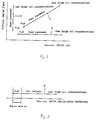
- supply patterns (A) (B) and (C) for lubricating oil and fuel can be set as shown in Figure 2.
- Supply pattern (A) is a setting example in which the concentration of lubricating oil is changed depending on engine speed, the concentration being increased with an increase in engine speed.
- Supply pattern (B) is another example of setting in which the concentration of lubricating oil is changed in terms of the engine load thus the concentration of oil in the oil/fuel mixture being increased with an increase in engine load.
- supply pattern (C) is another example of setting in which the concentration of lubricating oil is changed depending on both engine speed and load thus that the concentration being changed proportionally with respect to engine speed and engine load.
- the control unit 40 it is also possible to change the fuel flow rate while keeping the lubricating oil flow rate constant, to change the lubricating oil flow rate while keeping the fuel flow rate constant or to change both the flow rates of lubricating oil and fuel.
- a supply pattern (D) of lubricating oil and fuel can be achieved in response to the temperature of the engine cooling water.
- This supply pattern (D) is a setting example in which the concentration of lubricating oil is changed in response to the cooling water temperature of the engine such that the flow rate of the lubricating oil being increased accept when the engine is initially warming-up and the cooling water temperature is low.
- both lubricating oil and fuel are supplied and mixed together so that the lubricating oil is diluted with the fuel in order to reduce the viscosity of the oil.
- This dilution of the oil as well as the reciprocating movement of the piston 11 renders the piston 11 clean thereby reducing carbon deposits to piston 11 due to engine combustion and improve the reliable function of the piston 11.
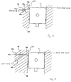
- the constitution of the oil/fuel mixture supply passage 36 is shown in said embodiments.
- lubricating oil and fuel are pre-mixed at a point upstream of the discharge opening on the piston sliding surface 100 and are pre-mixed at a point as close as possible to the inside surface (piston sliding surface 100) of the cylinder 10 in order to obtain a high response characteristic of changes in the mixing ratio between the lubricating oil and fuel.
- the fuel passage 36a and the lubricating oil supply passage 36b are formed independently and open into the cavity 33c of larger cross-section.
- the cavity 36c opens to the inside wall 100 of the cylinder. This opening of the cavity 36c is located such that the piston 11 closes the discharge opening when the piston 11 reaches its bottom dead center.
- This layout permits fuel and lubricating oil to be mixed effectively in the cavity 36c so that the lubricating oil is diluted with the fuel to reduce the viscosity of the oil. This mixing as well as the reciprocating movement of the piston 11 renders the piston skirt surface clean thereby reducing carbon deposits on the piston 11.
- Such a layout permits fuel and lubricating oil to be pre-mixed in the mixing passage 36d which is short and opens to the inside wall 100 of the cylinder 10 thus assuring a high responsiveness to changes in the mixing ratio between fuel and oil, reducing the viscosity of the lubricating oil by means of its dilution through the additional fuel.
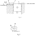
- FIGs 6 and 7 another embodiment is shown which differs from the preceding embodiments by means of the absence of a pre-mixing cavity or oil/fuel mixture supply passage but the provision of a fuel supply passage 36a and a lubricating oil supply passage 36b both being formed independently from each other and both opening separately to the inside wall (piston sliding surface) 100 of the cylinder 10.
- the openings of the fuel supply passage 36a and the lubricating oil supply passage 36b are located in parallel to each other at about the same level as shown in Figure 7 so that both being closed when the piston 11 aproaches its bottom dead center.
- both passageways 36a, 36b open to the cylinder bore below the bottom dead center of the piston 11.
- the fuel supplied from the fuel supply passage 36a and the lubricating oil supplied from the lubricating oil supply passage 36b mix on the piston sliding surface 100 of the cylinder 10 said mixing-up being promoted by the reciprocating movement of the piston 11 so that the lubricating oil is sufficiently diluted with fuel to reduce the viscosity of the oil. Also in this way deposition of carbon particles onto the piston surface is minimized.
Landscapes
- Engineering & Computer Science (AREA)
- General Engineering & Computer Science (AREA)
- Mechanical Engineering (AREA)
- Chemical & Material Sciences (AREA)
- Combustion & Propulsion (AREA)
- Lubrication Of Internal Combustion Engines (AREA)
- Fuel-Injection Apparatus (AREA)
Applications Claiming Priority (2)
| Application Number | Priority Date | Filing Date | Title |
|---|---|---|---|
| JP39412/93 | 1993-02-03 | ||
| JP5039412A JPH06229219A (ja) | 1993-02-03 | 1993-02-03 | 2サイクルエンジンの潤滑装置 |
Publications (2)
| Publication Number | Publication Date |
|---|---|
| EP0609866A1 true EP0609866A1 (fr) | 1994-08-10 |
| EP0609866B1 EP0609866B1 (fr) | 1997-05-07 |
Family
ID=12552282
Family Applications (1)
| Application Number | Title | Priority Date | Filing Date |
|---|---|---|---|
| EP94101570A Expired - Lifetime EP0609866B1 (fr) | 1993-02-03 | 1994-02-02 | Moteur à combustion interne à deux temps et procédé pour la lubrification directe d'un piston |
Country Status (4)
| Country | Link |
|---|---|
| US (1) | US5370089A (fr) |
| EP (1) | EP0609866B1 (fr) |
| JP (1) | JPH06229219A (fr) |
| DE (1) | DE69402999T2 (fr) |
Cited By (6)
| Publication number | Priority date | Publication date | Assignee | Title |
|---|---|---|---|---|
| FR2771448A1 (fr) * | 1997-11-21 | 1999-05-28 | Inst Francais Du Petrole | Procede de controle du debit d'huile dans un moteur deux temps a graissage separe et un moteur associe |
| WO2002023016A1 (fr) * | 2000-09-15 | 2002-03-21 | Wacker Construction Equipment Ag | Moteur a deux temps a lubrification minimale |
| DE10255450A1 (de) * | 2002-11-28 | 2004-06-09 | Daimlerchrysler Ag | Verfahren zum Schmieren einer Brennkraftmaschine |
| WO2005103456A2 (fr) | 2004-04-22 | 2005-11-03 | Wacker Construction Equipment Ag | Alimentation en huile pour un moteur a combustion interne |
| US7156056B2 (en) | 2004-06-10 | 2007-01-02 | Achates Power, Llc | Two-cycle, opposed-piston internal combustion engine |
| US7360511B2 (en) | 2004-06-10 | 2008-04-22 | Achates Power, Inc. | Opposed piston engine |
Families Citing this family (12)
| Publication number | Priority date | Publication date | Assignee | Title |
|---|---|---|---|---|
| JPH0754628A (ja) * | 1993-08-09 | 1995-02-28 | Yamaha Motor Co Ltd | 筒内燃料噴射式2サイクルエンジンの潤滑装置 |
| JPH0814093A (ja) * | 1994-06-24 | 1996-01-16 | Sanshin Ind Co Ltd | 2サイクルエンジンの始動制御装置 |
| US5749339A (en) * | 1996-02-28 | 1998-05-12 | Cummins Engine Company, Inc. | Electronically controlled continuous lubricating oil replacement system |
| US5826556A (en) * | 1997-04-24 | 1998-10-27 | Brunswick Corporation | Engine lubrication circuit with alternating lubrication paths |
| JPH11324631A (ja) * | 1998-05-14 | 1999-11-26 | Kioritz Corp | 内燃エンジンの分離潤滑装置 |
| US6516756B1 (en) | 1999-06-09 | 2003-02-11 | Sanshin Kogyo Kabushiki Kaisha | Fuel injection system for marine engine |
| US6295971B1 (en) | 2000-05-25 | 2001-10-02 | Cummins Engine Company, Inc. | Lubricating oil and fuel blending system |
| AU2003211485A1 (en) * | 2002-03-05 | 2003-09-16 | Ntn Corporation | Rolling bearing lubricating method and device |
| JP2003336512A (ja) * | 2002-05-20 | 2003-11-28 | Yamaha Marine Co Ltd | 2サイクルエンジンの潤滑油ポンプ制御方法 |
| DE202012101134U1 (de) * | 2012-03-29 | 2013-07-01 | Makita Corporation | Brennkraftmaschine, insbesondere 2-Takt-Brennkraftmaschine |
| CN103422933A (zh) * | 2012-05-14 | 2013-12-04 | 瓦锡兰瑞士公司 | 用于润滑往复活塞式燃烧发动机的缸中活塞结构的方法和汽缸润滑装置 |
| US9926887B2 (en) * | 2015-08-06 | 2018-03-27 | International Business Machines Corporation | Managing fuel oil mixture in engines |
Citations (5)
| Publication number | Priority date | Publication date | Assignee | Title |
|---|---|---|---|---|
| DE957354C (de) * | 1952-12-06 | 1957-01-31 | Motorenfabrik Darmstadt G M B | Zylinderschmierung von schlitzgesteuerten Brennkraftmaschinen |
| DE1175489B (de) * | 1960-11-12 | 1964-08-06 | Kugelfischer G Schaefer & Co | Schmieroelpumpe zur Druckoelschmierung von Brennkraftmaschinen, insbesondere Zweitakt-Leichtkraftstoff-Brennkraftmaschinen |
| JPS57203810A (en) * | 1981-01-08 | 1982-12-14 | Kawasaki Heavy Ind Ltd | Lubricating device of two cycle engine |
| JPH03260311A (ja) * | 1990-03-09 | 1991-11-20 | Suzuki Motor Corp | 二サイクルエンジンの潤滑オイル供給装置 |
| JPH04362209A (ja) * | 1991-06-07 | 1992-12-15 | Yamaha Motor Co Ltd | 空気燃料噴射式2サイクルエンジンの潤滑装置 |
Family Cites Families (10)
| Publication number | Priority date | Publication date | Assignee | Title |
|---|---|---|---|---|
| DE2546273C2 (de) * | 1975-10-16 | 1984-11-22 | Audi Nsu Auto Union Ag, 7107 Neckarsulm | Vorrichtung zur Regelung der Kolbenölkühlung für eine Kolbenbrennkraftmaschine |
| FR2476210A1 (fr) * | 1980-02-19 | 1981-08-21 | Crepelle & Cie | Dispositif d'alimentation en combustible et de regulation de la viscosite de ce combustible |
| JPS57181914A (en) * | 1981-05-02 | 1982-11-09 | Honda Motor Co Ltd | Heater for lubricating oil of internal combustion engine |
| JPS6053608A (ja) * | 1983-09-01 | 1985-03-27 | Nippon Denso Co Ltd | エンジン用潤滑油温度制御装置 |
| EP0166698A3 (fr) * | 1984-06-29 | 1987-01-14 | Otto Münch | Circuit d'huile, particulièrement pour un moteur à combustion interne |
| JPS61229914A (ja) * | 1985-04-02 | 1986-10-14 | Nissan Motor Co Ltd | 内燃機関の潤滑装置 |
| JPH01280610A (ja) * | 1988-05-02 | 1989-11-10 | Mazda Motor Corp | アルコール燃料エンジンの潤滑装置 |
| DE3831490A1 (de) * | 1988-09-16 | 1990-03-29 | Stihl Maschf Andreas | Kraftstoffeinspritzvorrichtung |
| DE68909050T2 (de) * | 1989-11-06 | 1994-03-24 | Kyoseki Seihin Gijutsu Kenk | Abnutzungsdetektionsvorrichtung für Schmieröl. |
| JPH03242410A (ja) * | 1990-02-21 | 1991-10-29 | Nissan Motor Co Ltd | エンジンの潤滑装置 |
-
1993
- 1993-02-03 JP JP5039412A patent/JPH06229219A/ja active Pending
-
1994
- 1994-01-31 US US08/189,210 patent/US5370089A/en not_active Expired - Fee Related
- 1994-02-02 DE DE69402999T patent/DE69402999T2/de not_active Expired - Fee Related
- 1994-02-02 EP EP94101570A patent/EP0609866B1/fr not_active Expired - Lifetime
Patent Citations (5)
| Publication number | Priority date | Publication date | Assignee | Title |
|---|---|---|---|---|
| DE957354C (de) * | 1952-12-06 | 1957-01-31 | Motorenfabrik Darmstadt G M B | Zylinderschmierung von schlitzgesteuerten Brennkraftmaschinen |
| DE1175489B (de) * | 1960-11-12 | 1964-08-06 | Kugelfischer G Schaefer & Co | Schmieroelpumpe zur Druckoelschmierung von Brennkraftmaschinen, insbesondere Zweitakt-Leichtkraftstoff-Brennkraftmaschinen |
| JPS57203810A (en) * | 1981-01-08 | 1982-12-14 | Kawasaki Heavy Ind Ltd | Lubricating device of two cycle engine |
| JPH03260311A (ja) * | 1990-03-09 | 1991-11-20 | Suzuki Motor Corp | 二サイクルエンジンの潤滑オイル供給装置 |
| JPH04362209A (ja) * | 1991-06-07 | 1992-12-15 | Yamaha Motor Co Ltd | 空気燃料噴射式2サイクルエンジンの潤滑装置 |
Non-Patent Citations (4)
| Title |
|---|
| AN.: "TWO-STROKE OIL DELIVERY SYSTEM USING GASOLINE AS A SOLVENT", RESEARCH DISCLOSURE, vol. 1992, no. 340, 1 August 1992 (1992-08-01), EMSWORTH, XP000324126 * |
| PATENT ABSTRACTS OF JAPAN vol. 016, no. 069 (M - 1212) 20 February 1992 (1992-02-20) * |
| PATENT ABSTRACTS OF JAPAN vol. 017, no. 233 (M - 1407) 12 May 1993 (1993-05-12) * |
| PATENT ABSTRACTS OF JAPAN vol. 7, no. 59 (M - 199) 11 March 1983 (1983-03-11) * |
Cited By (14)
| Publication number | Priority date | Publication date | Assignee | Title |
|---|---|---|---|---|
| FR2771448A1 (fr) * | 1997-11-21 | 1999-05-28 | Inst Francais Du Petrole | Procede de controle du debit d'huile dans un moteur deux temps a graissage separe et un moteur associe |
| WO1999027236A1 (fr) * | 1997-11-21 | 1999-06-03 | Institut Français Du Petrole | Procede de controle du debit d'huile dans un moteur deux temps a graissage separe et un moteur associe |
| WO2002023016A1 (fr) * | 2000-09-15 | 2002-03-21 | Wacker Construction Equipment Ag | Moteur a deux temps a lubrification minimale |
| US6932046B2 (en) | 2000-09-15 | 2005-08-23 | Wacker Construction Equipment Ag | Two cycle engine having minimal lubrication |
| DE10255450A1 (de) * | 2002-11-28 | 2004-06-09 | Daimlerchrysler Ag | Verfahren zum Schmieren einer Brennkraftmaschine |
| WO2005103456A2 (fr) | 2004-04-22 | 2005-11-03 | Wacker Construction Equipment Ag | Alimentation en huile pour un moteur a combustion interne |
| US7156056B2 (en) | 2004-06-10 | 2007-01-02 | Achates Power, Llc | Two-cycle, opposed-piston internal combustion engine |
| US7360511B2 (en) | 2004-06-10 | 2008-04-22 | Achates Power, Inc. | Opposed piston engine |
| US7546819B2 (en) | 2004-06-10 | 2009-06-16 | Achates Power. | Two-stroke, opposed-piston internal combustion engine |
| US7549401B2 (en) | 2004-06-10 | 2009-06-23 | Achates Power, Inc. | Two-cycle, opposed-piston internal combustion engine |
| US7591235B2 (en) | 2004-06-10 | 2009-09-22 | Achates Power, Inc. | Opposed piston engine with piston compliance |
| US7784436B2 (en) | 2004-06-10 | 2010-08-31 | Achates Power, Inc. | Two-cycle, opposed-piston internal combustion engine |
| US7861679B2 (en) | 2004-06-10 | 2011-01-04 | Achates Power, Inc. | Cylinder and piston assemblies for opposed piston engines |
| US8281755B2 (en) | 2004-06-10 | 2012-10-09 | Achates Power, Inc. | Internal combustion engine with provision for lubricating pistons |
Also Published As
| Publication number | Publication date |
|---|---|
| EP0609866B1 (fr) | 1997-05-07 |
| DE69402999T2 (de) | 1997-08-21 |
| US5370089A (en) | 1994-12-06 |
| DE69402999D1 (de) | 1997-06-12 |
| JPH06229219A (ja) | 1994-08-16 |
Similar Documents
| Publication | Publication Date | Title |
|---|---|---|
| EP0609866B1 (fr) | Moteur à combustion interne à deux temps et procédé pour la lubrification directe d'un piston | |
| US5063881A (en) | Ceramic engine | |
| US4579093A (en) | Fuel injection, two cycle engine | |
| US4945864A (en) | Two cycle engine piston lubrication | |
| US5806631A (en) | Piston pin lubrication | |
| US7198020B1 (en) | Lubrication systems and methods for an internal combustion engine | |
| US5396867A (en) | Two-cycle engine | |
| US4989555A (en) | Lubricant supply for two cycle engine | |
| JPS62147045A (ja) | 2サイクルクランクケ−ス掃気式エンジン及びその燃料の霧化を改善する方法 | |
| US5769050A (en) | Prechamber for diesel engine | |
| US5701856A (en) | Separate oiling type two cycle engine | |
| US4694786A (en) | One-cylinder, two-stroke internal combustion engine with crankcase scavenging | |
| JPH02125961A (ja) | 2サイクル内燃機関用燃料供給装置 | |
| JP2979007B2 (ja) | 2サイクルエンジンの潤滑装置 | |
| WO2023176435A1 (fr) | Moteur à deux temps | |
| US6792900B2 (en) | Lubrication system for two-cycle engine | |
| JP3487534B2 (ja) | エンジンの潤滑構造 | |
| JPS6313378Y2 (fr) | ||
| RU2002969C1 (ru) | Система смазки двухтактного двигател внутреннего сгорани | |
| JPH01277612A (ja) | 内燃機関の潤滑装置 | |
| WO1998053191A1 (fr) | Moteur deux-temps a combustion interne | |
| US1960093A (en) | Compression ignition internal combustion engine | |
| JPH06173830A (ja) | 燃料噴射式内燃機関 | |
| SU398758A1 (ru) | Способ смазки цилиндра двухтактного дизеля | |
| JPH084515A (ja) | 2サイクルエンジンの潤滑装置 |
Legal Events
| Date | Code | Title | Description |
|---|---|---|---|
| PUAI | Public reference made under article 153(3) epc to a published international application that has entered the european phase |
Free format text: ORIGINAL CODE: 0009012 |
|
| AK | Designated contracting states |
Kind code of ref document: A1 Designated state(s): DE FR GB IT |
|
| 17P | Request for examination filed |
Effective date: 19950118 |
|
| 17Q | First examination report despatched |
Effective date: 19950405 |
|
| GRAG | Despatch of communication of intention to grant |
Free format text: ORIGINAL CODE: EPIDOS AGRA |
|
| GRAH | Despatch of communication of intention to grant a patent |
Free format text: ORIGINAL CODE: EPIDOS IGRA |
|
| GRAH | Despatch of communication of intention to grant a patent |
Free format text: ORIGINAL CODE: EPIDOS IGRA |
|
| GRAA | (expected) grant |
Free format text: ORIGINAL CODE: 0009210 |
|
| AK | Designated contracting states |
Kind code of ref document: B1 Designated state(s): DE FR GB IT |
|
| PG25 | Lapsed in a contracting state [announced via postgrant information from national office to epo] |
Ref country code: FR Effective date: 19970507 |
|
| REF | Corresponds to: |
Ref document number: 69402999 Country of ref document: DE Date of ref document: 19970612 |
|
| EN | Fr: translation not filed | ||
| PGFP | Annual fee paid to national office [announced via postgrant information from national office to epo] |
Ref country code: GB Payment date: 19980126 Year of fee payment: 5 |
|
| PGFP | Annual fee paid to national office [announced via postgrant information from national office to epo] |
Ref country code: DE Payment date: 19980206 Year of fee payment: 5 |
|
| PLBE | No opposition filed within time limit |
Free format text: ORIGINAL CODE: 0009261 |
|
| STAA | Information on the status of an ep patent application or granted ep patent |
Free format text: STATUS: NO OPPOSITION FILED WITHIN TIME LIMIT |
|
| 26N | No opposition filed | ||
| PG25 | Lapsed in a contracting state [announced via postgrant information from national office to epo] |
Ref country code: GB Free format text: LAPSE BECAUSE OF NON-PAYMENT OF DUE FEES Effective date: 19990202 |
|
| GBPC | Gb: european patent ceased through non-payment of renewal fee |
Effective date: 19990202 |
|
| PG25 | Lapsed in a contracting state [announced via postgrant information from national office to epo] |
Ref country code: DE Free format text: LAPSE BECAUSE OF NON-PAYMENT OF DUE FEES Effective date: 19991201 |
|
| PG25 | Lapsed in a contracting state [announced via postgrant information from national office to epo] |
Ref country code: IT Free format text: LAPSE BECAUSE OF NON-PAYMENT OF DUE FEES Effective date: 20050202 |