EP0606067B1 - Prozesssteuervorrichtung eines elektrophotographischen Gerätes - Google Patents
Prozesssteuervorrichtung eines elektrophotographischen Gerätes Download PDFInfo
- Publication number
- EP0606067B1 EP0606067B1 EP94100060A EP94100060A EP0606067B1 EP 0606067 B1 EP0606067 B1 EP 0606067B1 EP 94100060 A EP94100060 A EP 94100060A EP 94100060 A EP94100060 A EP 94100060A EP 0606067 B1 EP0606067 B1 EP 0606067B1
- Authority
- EP
- European Patent Office
- Prior art keywords
- toner
- density
- process control
- electrophotographic
- image
- Prior art date
- Legal status (The legal status is an assumption and is not a legal conclusion. Google has not performed a legal analysis and makes no representation as to the accuracy of the status listed.)
- Expired - Lifetime
Links
Images


Classifications
-
- G—PHYSICS
- G03—PHOTOGRAPHY; CINEMATOGRAPHY; ANALOGOUS TECHNIQUES USING WAVES OTHER THAN OPTICAL WAVES; ELECTROGRAPHY; HOLOGRAPHY
- G03G—ELECTROGRAPHY; ELECTROPHOTOGRAPHY; MAGNETOGRAPHY
- G03G15/00—Apparatus for electrographic processes using a charge pattern
- G03G15/50—Machine control of apparatus for electrographic processes using a charge pattern, e.g. regulating differents parts of the machine, multimode copiers, microprocessor control
- G03G15/5033—Machine control of apparatus for electrographic processes using a charge pattern, e.g. regulating differents parts of the machine, multimode copiers, microprocessor control by measuring the photoconductor characteristics, e.g. temperature, or the characteristics of an image on the photoconductor
- G03G15/5041—Detecting a toner image, e.g. density, toner coverage, using a test patch
-
- G—PHYSICS
- G03—PHOTOGRAPHY; CINEMATOGRAPHY; ANALOGOUS TECHNIQUES USING WAVES OTHER THAN OPTICAL WAVES; ELECTROGRAPHY; HOLOGRAPHY
- G03G—ELECTROGRAPHY; ELECTROPHOTOGRAPHY; MAGNETOGRAPHY
- G03G15/00—Apparatus for electrographic processes using a charge pattern
- G03G15/04—Apparatus for electrographic processes using a charge pattern for exposing, i.e. imagewise exposure by optically projecting the original image on a photoconductive recording material
- G03G15/045—Apparatus for electrographic processes using a charge pattern for exposing, i.e. imagewise exposure by optically projecting the original image on a photoconductive recording material with means for charging or discharging distinct portions of the charge pattern on the recording material, e.g. for contrast enhancement or discharging non-image areas
- G03G15/047—Apparatus for electrographic processes using a charge pattern for exposing, i.e. imagewise exposure by optically projecting the original image on a photoconductive recording material with means for charging or discharging distinct portions of the charge pattern on the recording material, e.g. for contrast enhancement or discharging non-image areas for discharging non-image areas
-
- G—PHYSICS
- G03—PHOTOGRAPHY; CINEMATOGRAPHY; ANALOGOUS TECHNIQUES USING WAVES OTHER THAN OPTICAL WAVES; ELECTROGRAPHY; HOLOGRAPHY
- G03G—ELECTROGRAPHY; ELECTROPHOTOGRAPHY; MAGNETOGRAPHY
- G03G2215/00—Apparatus for electrophotographic processes
- G03G2215/00025—Machine control, e.g. regulating different parts of the machine
- G03G2215/00029—Image density detection
- G03G2215/00033—Image density detection on recording member
- G03G2215/00037—Toner image detection
- G03G2215/00042—Optical detection
-
- G—PHYSICS
- G03—PHOTOGRAPHY; CINEMATOGRAPHY; ANALOGOUS TECHNIQUES USING WAVES OTHER THAN OPTICAL WAVES; ELECTROGRAPHY; HOLOGRAPHY
- G03G—ELECTROGRAPHY; ELECTROPHOTOGRAPHY; MAGNETOGRAPHY
- G03G2215/00—Apparatus for electrophotographic processes
- G03G2215/00025—Machine control, e.g. regulating different parts of the machine
- G03G2215/00071—Machine control, e.g. regulating different parts of the machine by measuring the photoconductor or its environmental characteristics
- G03G2215/00084—Machine control, e.g. regulating different parts of the machine by measuring the photoconductor or its environmental characteristics the characteristic being the temperature
-
- G—PHYSICS
- G03—PHOTOGRAPHY; CINEMATOGRAPHY; ANALOGOUS TECHNIQUES USING WAVES OTHER THAN OPTICAL WAVES; ELECTROGRAPHY; HOLOGRAPHY
- G03G—ELECTROGRAPHY; ELECTROPHOTOGRAPHY; MAGNETOGRAPHY
- G03G2215/00—Apparatus for electrophotographic processes
- G03G2215/04—Arrangements for exposing and producing an image
- G03G2215/0429—Changing or enhancing the image
- G03G2215/0431—Producing a clean non-image area, i.e. avoiding show-around effects
- G03G2215/0448—Charge-erasing means for the non-image area
Definitions
- the present invention relates to a process control apparatus of electrophotographic apparatus which controls each section of an electrophotographic process in accordance with the density of a reference toner image so as to obtain a stably formed picture image.
- the surface potential of a photoreceptor greatly changes according to the environmental change such as a temperature change.
- OPC Organic Photoconductive Conductor
- the surface potential drops down by about 100V under a low temperature circumstance compared to that of the normal temperatures, thereby causing the occurrence of a residual potential. Therefore, the toners move to white parts of the copying picture image, thereby causing the fog.
- the developer is so sensitive to a humidity change because of its powder.
- the developer has a high electrical resistance, thereby resulting in that the frictionally charged toner has a strong charge holding capability.
- the charged amount of the toner increases, thereby changing the picture quality.
- the developer deteriorates due to the repeated using thereof, thereby causing the great change of the picture quality.
- the conventional electrophotographic apparatus stabilizes the picture quality by measuring the electrostatic latent image formed on the photoreceptor so as to control the forming of electrostatic latent image in accordance with the measured results (see, for example, the Japanese examined patent publication No. 61-29502/1986).
- Such example is provided with means for detecting the optical density of the toner image on the photoreceptor so as to detect the change of quality and control the electrophotographic process in accordance with the detected results, so that the optimum picture quality can be obtained.
- a plurality of square toner patches of about 30mm ⁇ 30mm as the toner image are provided on the photoreceptor so that each toner patch has a different density from other toner patches, thereby individually detecting the optical density thereof.
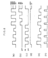
- the following description deals with the process of detection of the optical density in accordance with the formation of the toner patches with reference to a time chart of Figs. 6(a) through 6(f).
- the drum-type photoreceptor is charged on respective different positions by different grid voltages -500V, -400V, and -300V in this order (see Fig. 6(a)).
- a copy lamp is turned off with respect to the charged area, so that the exposure operation is not carried out (see Fig. 6(b)), and during the period a blank lamp is on as shown in Fig. 6(c).
- the photoreceptor is charged by a constant grid voltage of -700V. Then, the charged area of the photoreceptor is exposed by the copy lamp having respective applying voltages 60V, 65V, and 70V. Three toner patches having different density are formed by developing the charged area with a constant developing bias voltage of -200V, and each density of the toner patches is detected by an optical sensor in the foregoing manner. Then, the applying voltage of the copy lamp is controlled so as to correct the picture quality.
- the process control based on the toner patches is carried out after (1) the turn-on operation of the main power of the copying machine and before or after (2) the copying operation, so as not to bring any troubles during the copying operation.
- Prior art document US-A-5 170 210 discloses an image forming apparatus comprising a temperature detector, a humidity detector and an atmospheric pressure detector. Further, a first detector for detecting densities of images formed on the photosenstive drum, a second detector for detecting densities of images transferred on papers and a third detector for detecting the density of the image on the photosensitive drum after transferring the previous image onto the paper are provided in the apparatus.
- the amount of toner supplied to a developing unit is controlled dependent on environmental conditions as detected by the temperature detector and the first detector, for example.
- the density of an image as detected by the first detector is compared with a reference value to control toner density. This control process may be corrected by detection signals supplied from the second and third detectors.
- the surface potential of the photosensitive drum and the charge amount of the developer are controlled in accordance with image densities and environmental conditions, such as temperature, humidity, and atmospheric pressure, around the photosensitive drum.
- prior art document JP-A-55 055 349 describes a control unit of an electrophotographic copying apparatus wherein an original document and a reference target provided as the lower side of an original document platen are exposed with an exposure lamp to detect the density of a toner image of the reference target.
- prior art document JP-A-58-152 273 discloses an electrophotographic copying machine comprising means for correcting the quantity of the light projected for projecting an image so that a reference latent image on a photoreceptor has a desired surface potential, detecting means for detecting conditions for use that affect the characteristics of a photoreceptor, and means for successively correcting a reference equation expressing conditions for obtaining an optimum quantity of the light projected for projecting an image in accordance with the corrected quantity of the light projected for projecting an image and the detected conditions for use.
- the present invention provides a process control apparatus as specified in claim 1.
- the apparatus of the invention comprises especially:
- the information processing means forms each reference image between every two toner images for the picture image, and controls each section of the electrophotographic process upon receipt of a plurality of detected results from the density detecting means.
- the process control is carried out by making use of the period of time between every two toner image formations for the picture image formation; it can be avoided that the job efficiency deteriorates. Since the control data obtained from the reference toner image is soon used for the toner image formation for the picture image, the process control improves in accuracy, thereby enabling to optimize the picture image formation.
- the information processing means is arranged so as to stepwise control a degree of an exposure during controlling each section of the electrophotographic process, thereby obtaining an optimum exposure state.
- the information processing means is arranged so as to stepwise control. In such case, according to the stepwise control, the great change in the picture quality during the picture image formations can be avoided. So, the process control improves in accuracy.
- Figs. 1(a) through 1(f) are time charts showing respectively time charts of a process control for charge potentials in a copying machine having a process control apparatus of an embodiment in accordance with the present invention.
- Figs. 2(a) through 2(f) are time charts showing respectively a process control for a copy lamp in a copying machine having the process control apparatus.
- Fig. 3 is a schematic explanatory diagram showing the structure of a copying machine having the process control apparatus.
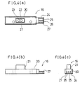
- Figs. 4(a) through 4(c) show the structure of an optical sensor of the copying machine
- Fig. 4(a) is a plan view
- Fig. 4(b) is a front view
- Fig. 4(c) is a side view.
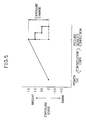
- Fig. 5 is an explanatory diagram showing a state where the process control is carried out step by step in the process control apparatus.
- Figs. 6(a) through 6(f) are time charts showing respectively a process control for forming a plurality of toner patches in a conventional copying machine.
- a copying machine in accordance with the present embodiment is provided with a photoreceptor drum 1 having a cylindrically shaped photoreceptor (see Fig. 3).
- the photoreceptor drum 1 is rotatably provided in a direction A in the copying machine.
- the photoreceptor drum 1 has a drum base as a photoreceptor base made of an aluminum pipe having a pipe thickness of about 2mm, a diameter of about 100mm, and a length of about 340mm, and an outer peripheral surface of the drum base is uniformly coated with an electrical charge generating layer having a thickness of 1 micron ( ⁇ m) and an electrical charge transporting layer having a thickness of 34 micron in this order so as to form an organic semiconductor.
- a document place plate 2 of transparent material for placing a document M thereon is provided above the photoreceptor drum 1.
- An exposure optical system 3 is provided between the document place plate 2 and the photoreceptor drum 1.
- the exposure optical system 3 is composed of a copy lamp 4, a plurality of mirrors 5, and a lens 6.
- the exposure optical system 3 carries out an optical scanning of the document M in accordance with the light projected from the copy lamp 4 (see the alternate long and short dash line of Fig. 3) by moving the document place plate 2, and directs the reflected light to the surface of the photoreceptor drum 1 through the mirrors 5 and lens 6 so as to carry out the exposure operation.
- an electrostatic latent image is formed in accordance with a picture image pattern of the document M on the surface of the photoreceptor drum 1 which is uniformly charged by a main charger 7 (described later).
- the main charger 7 There is provided around the photoreceptor drum 1 the main charger 7, a blank lamp 8, a developing unit 9, a transfer charger 10, a separating charger 11, a cleaner unit 12, an erase lamp 13, and other elements.
- the main charger 7 is a charging device for charging the surface of the photoreceptor drum 1 by a target electric potential in accordance with the controlling of a voltage, i.e., a grid voltage, applied to a grid electrode 7a which is provided between the photoreceptor drum 1 and the main charger 7.
- the blank lamp 8 is an erase device for carrying out the erasing by exposing an area with no picture image on the surface of the photoreceptor drum 1.
- the developing unit 9 is a developing device for visualizing the latent image as the toner image by attaching the toner to the latent image formed on the surface of the photoreceptor drum 1.
- the transfer charger 10 supplies an electric potential onto the surface of the photoreceptor drum 1 so as to transfer the toner image formed on the surface of the photoreceptor drum 1 to a transfer sheet P.
- the separating charger 11 supplies an electric potential onto the surface of the photoreceptor drum 1 so as to separate the transfer sheet P, to which the toner image is transferred, from the photoreceptor drum 1.
- the cleaner unit 12 is a cleaning device for recovering the residual toners on the surface of the photoreceptor drum 1.
- the erase lamp 13 is an erase device for erasing the residual electric charges on the surface of the photoreceptor drum 1 before the main charger 13 charges the photoreceptor drum 1.
- a fusing unit 14 is provided on a discharge side of the present copying machine. The fusing unit 14 fixes with heat the toner image onto the transfer sheet P which is separated from the photoreceptor drum 1 and is fed by a feeder (not shown).
- the present copying machine is provided with a process control section 15 for controlling each section of the electrophotographic process.
- the process control section 15 is composed of an optical sensor 16 as density detecting means for detecting the density of the outer peripheral surface of the photoreceptor drum 1, a standard white plate 32 which is provided on a starting end side of the document place plate 2, an amplifier 17, an A/D converter 18, and a CPU 19, so as to control a copying process section composed of the photoreceptor drum 1 and other devices.
- the optical sensor 16 is a detecting device which is provided in the vicinity of a lower side the cleaner unit 12.
- the optical sensor 16 projects the light such as the infrared light rays direct toward the surface of the photoreceptor drum 1 and receives the reflected light by use of a photo-transistor or other device.
- the optical sensor 16 detects the optical density of the toner patch as a reference toner image formed on the surface of the photoreceptor drum 1, and outputs the detected result as a detected signal.
- the optical sensor 16 has an outline made by a case 20 of a long thin shape.
- An attaching section 21 is provided so as to project in the near center section of an outer surface of the case 20 (see Figs. 4(a) through 4(c)).
- the attaching section 21 is provided with an infrared light generating diode 22 for projecting the light having a wavelength of 890nm and a photo-transistor 23, the elements 22 and 23 being located close with each other.
- One end side of the case 20 is provided with a terminal section 24 which is provided like a connector.
- the terminal section 24 is provided with a power source terminal 25, an output terminal 26, and a GND terminal 27 in a predetermined interval.
- the optical sensor 16 is connected with the CPU 19 through the amplifier 17 and A/D converter 18 (see Fig. 3).
- the detected signal of the optical sensor 16 is amplified by the amplifier 17, and thereafter is converted into a binary signal by the A/D converter 18 so as to output the binary signal as a density data to the CPU 19.
- the CPU 19 is respectively connected with a lamp driving circuit 28, a power source 29, a developing bias power source 30, and a toner supply driving device 31.
- the lamp driving circuit 28 is a power source for lighting the copy lamp 4.
- the power source 29 is a power source for generating the grid voltage which is supplied to the grid electrode 7a of the main charger 7.
- the developing bias power source 30 is a power source for generating the developing voltage which is supplied to a developing sleeve 9a of the developing unit 9.
- the toner supply driving device 31 is a device for supplying the toner from a toner hopper (not shown) to a developing vessel 9b.
- the developing bias is supplied in order to avoid that the residual electric potential of the bright section, which is about -80V to -100V and is generated after the surface of the photoreceptor drum 1 has been exposed by supplying the bias to the developing sleeve 9a, attracts the toner.
- the CPU 19 outputs control signals to the lamp driving circuit 28, power source 29, developing bias power source 30, and toner supply driving device 31 so that the optimum controllings are carried out with respect to the lamp supplying voltage, grid voltage, developing voltage, and the toner supplying amount to the developing vessel 9b respectively.
- the CPU 19 executes a program for forming the toner patches, thereby making totally six toner patches.
- each toner patch is supplied by a different grid voltage of the grid electrode 7a and a different voltage applied to the copy lamp 4, thereby causing the charging voltages or surface electric potentials of the photoreceptor drum 1 to be different from each other.
- each toner patch haying a different toner density to be visualized is obtained.
- the CPU 19 forms a toner patch between every two toner images, the copying operation being carried out in accordance with the plurality of toner images, and has a function of information processing means by which each section of the copying processes is controlled upon receipt of a plurality of detected results from the optical sensor 16.
- the CPU 19 controls a timer (not shown) so as to start counting of time which is used for making a timing of sampling the detection of the toner patches (described later) when the blank lamp 8 is turned off.
- each controlling value of the processes such as the voltage applied to the copy lamp 4 greatly changes.
- the CPU 19 carries out stepwise controlling of each section of the copying processes so as to stepwise change the controlling value one after the other. Note that the stepwise controlling is carried out when the change becomes greater than a predetermined value which is preliminarily set.
- each toner patch is formed by making use of the period of time between the copying operations. More specifically, as shown in the time chart of Figs. 1(a) through 1(f), a toner patch forming section P for forming one toner patch on the photoreceptor drum 1 is provided between copying picture image forming sections F and B.
- the main charger 7 charges the photoreceptor drum 1 by a grid voltage of -500V for example during the period of time between (1) the time when a toner image is formed on the first copying picture image forming section F in accordance with the first copying operation and (2) the time when the toner image is formed on the second copying picture image forming section B in accordance with the second copying operation.
- the blank lamp 8 (see Fig. 1(b)) is turned off as soon as the grid voltage (see Fig. 1(a)) is turned on, and is kept turned off until the end of the toner patch forming section so as not to project the light.
- the copy lamp 4 (see Fig. 1(c)) is not turned on during the formation of the first three toner patches.
- the toner patch forming section P of the charged photoreceptor drum 1 becomes a latent image having the electrical charge amount varying depending on the grid voltage.
- a toner image as the toner patch is obtained.
- the blank lamp 8 is turned off, and simultaneously the timer (not shown) is operated so that the sampling for the detection of the optical sensor 16 is carried out with respect to the first toner patch after the time elapsing of 50ms (mili-second) for example (see Fig. 1(f)).
- the respective grid voltages -400V and - 300V are applied and the other conditions are the same as the foregoing ones, thereby forming the second and third toner patches.
- the samplings are carried out after the timer counts the respective predetermined time elapsings, the timer starting to count when the blank lamp 8 is turned off. Accordingly, the density detections of the toner patches are carried out when it reaching the middle section of the output of the optical sensor where the optical sensor 16 can stably output.
- the grid voltage, developing bias voltage and the like are controlled in accordance with the respective detected toner patches density so as to correct the picture quality.
- the voltage applied to the copy lamp 4 is controlled.
- another three toner patches are formed. Each toner patch is formed by making use of the period of time between the copying operations (see the time chart of Figs. 2(a) through 2(f)).
- the main charger 7 charges the photoreceptor drum 1 by a grid voltage of -700V during the period of time between (1) the time when the toner image is formed on the copying picture image forming section F in accordance with the fourth copying operation and (2) the time when the toner image is formed on the copying picture image forming section B in accordance with the fifth copying operation.
- the blank lamp 8 (see Fig. 2(b)) is turned off as soon as the grid voltage (see Fig. 2(a)) is turned on, and is kept turning off until the end of the toner patch forming section so as not to project the erasing light.
- the copy lamp 4 (see Fig. 2(c)) is turned on while being applied by 60V. The reflected light from the standard white plate 32 in accordance with the copy lamp 4 exposes the photoreceptor drum 1.
- the toner patch forming section P of the charged photoreceptor drum 1 becomes a latent image having the surface electric potential corresponding to the difference between the electrical charge amount corresponding to the grid voltage and the electrical charge amount erased by the copy lamp 4 exposure.
- the latent image is developed by the constant developing bias voltage of -200V (see Fig. 2(d))
- a toner image as the toner patch is obtained.
- the blank lamp 8 is turned off, and simultaneously the timer (not shown) is operated so that the sampling for the detection of the optical sensor 16 is carried out with respect to the fourth toner patch after elapsing the time of 50ms for example (see Fig. 2(f)).
- the respective voltages applied to the copy lamp 4 are 65V and 70V and the other conditions are the same as the foregoing ones, thereby forming the fifth and sixth toner patches having different density.
- the samplings are carried out after the timer counts the respective predetermined time elapsings, the timer starting to count when the blank lamp 8 is turned off.
- the picture quality correction is carried out after obtaining the detected data of the three toner patches having respective different density so that the picture quality is corrected by adjusting the voltage applied to the copy lamp 4.
- the above-mentioned picture quality correction is stepwise and divisionally carried out.
- the temperature inside the copying machine rises so that the picture image density gradually becomes bright.
- the exposure state is first controlled so as to have an exposure value of 1.0 at the first stage; (2) the exposure state is controlled so as to have an exposure value of 0.5 at the second stage; and (3) the exposure state is controlled so as to have an exposure value of 0.0, which is suitable for the exposure operation, at the third stage (see the solid line of Fig. 5).
- the CPU 19 as information processing means forms a toner patch between every two toner images for copying operation, and controls each section of the copying processes upon receipt of the plurality of the detected results from the optical sensor 16. Since the process controls are carried out by making use of the period of time between every two toner image formings for copying operation, it can be avoided that the job efficiency is reduced, i.e., the job efficiency deteriorates. Since the control data obtained from the toner patches is soon used for the toner image formation for copying operation, the process control is improved in accuracy.
- the CPU 19 as information processing means is arranged so as to stepwise control each section of the electrophotographic process when a plurality of toner images for the picture image is formed, the great change (see the broken lines of Fig. 5) of the picture quality can be avoided.
- the accuracy of the process control improves, thereby achieving the optimization of the picture image formation, and the great change of the picture quality can be avoided, thereby reducing the user's feeling of discrepancy for the copying machine.
- the process control apparatus of electrophotographic apparatus of the present invention is provided with information processing means for forming a reference toner image between every two toner images for a picture image, and for controlling each section of the electrophotographic process upon receipt of a plurality of the detected results from the density detecting means. Therefore, since the process control is carried out by making use of the period of time between every two toner image formations for the picture image formation, it can be avoided that the job efficiency deteriorates. Since the control data obtained from the toner patches is soon used for the toner image formation for the picture image, the process control improves in accuracy.
- Another process control apparatus of electrophotographic apparatus of the present invention is arranged such that the information processing means stepwise controls each section of the electrophotographic process during controlling of each section of the electrophotographic process.
Landscapes
- Physics & Mathematics (AREA)
- General Physics & Mathematics (AREA)
- Engineering & Computer Science (AREA)
- Microelectronics & Electronic Packaging (AREA)
- Control Or Security For Electrophotography (AREA)
Claims (7)
- Prozeßsteuergerät für ein elektrophotographisches Gerät, umfassend:eine Prozeßeinrichtung (19) zum Erzeugen eines Bezugstonersignales auf einem Photorezeptor (1) zwischen jeden zwei Erzeugungstonerbildern für eine Bildinformation, wobei die Tonerdichte von jedem Bezugstonerbild verschieden ist von derjenigen der vorangehenden Bezugstonerbilder,eine Dichtedetektoreinrichtung (16) zum optischen Erfassen der Dichte von jedem der Bezugstonerbilder, undeine Entscheidungseinrichtung (15) zum Entscheiden, ob die Dichte von jedem der Bezugstonerbilder richtig ist oder nicht, wodurchjeder Abschnitt eines elektrophotographischen Prozesses abhängig von der Entscheidungseinrichtung (15) so gesteuert ist, daß die Bildqualität eines erzeugten Bildes stabilisiert wird.
- Prozeßsteuergerät für ein elektrophotographisches Gerät nach Anspruch 1, bei dem die Tonerdichte von jedem Bezugstonerbild unterschiedlich von derjenigen der vorangehenden Bezugstonerbilder ist, indem eine Gitterspannung oder eine Spannungsversorgung zu einer Belichtungslampe (4) verändert werden.
- Prozeßsteuergerät für ein elektrophotographisches Gerät nach Anspruch 1 oder 2, bei dem das Bezugstonerbild ein Tonerfleck ist, und bei dem der elektrophotographische Prozeß während einer Zeitdauer zwischen jeden beiden Toner-bilderzeugungen für eine Kopieroperation gesteuert wird.
- Prozeßsteuergerät für ein elektrophotographisches Gerät nach Anspruch 3, bei dem die Prozeßeinrichtung (19) aufweist:eine Ladungssteuereinrichtung zum Steuern einer Ladespannung, die an dem Photorezeptor (1) anliegt, undeine Einrichtung zum Erzeugen eines Tonerflecks auf dem Photorezeptor (1) durch Entwickeln eines latenten Bildes mit einer elektrischen Ladungsmenge, die sich abhängig von der Ladespannung verändert, während eine vorbestimmte Entwicklungsvorspannung anliegt,wobei die Ladungssteuereinrichtung den Photorezeptor (1) durch eine verschiedene Ladespannung auflädt, so daß jeder Tonerfleck eine verschiedene zu visualisierende Tonerdichte hat.
- Prozeßsteuergerät für ein elektrophotographisches Gerät nach Anspruch 4, bei dem die Dichtedetektoreinrichtung (16) einen Umriß hat, der durch ein langes dünnes Gehäuse gebildet ist, ein Befestigungsabschnitt (21) vorgesehen ist, um in den nahen Mittenabschnitt einer Außenfläche des Gehäuses vorzuspringen, und der Befestigungsabschnitt (21) mit einer Leuchtdiode (22) und einem Phototransistor (23) versehen ist, die nahe beieinander angeordnet sind.
- Prozeßsteuergerät für ein elektrophotographisches Gerät nach Anspruch 1 oder 2, bei dem die Prozeßeinrichtung (19) angeordnet ist, um stufenweise einen Belichtungsgrad während eines Steuerns jedes Abschnittes des elektrophotographischen Prozesses zu steuern, um dadurch einen optimalen Belichtungszustand zu erhalten.
- Prozeßsteuergerät für ein elektrophotographisches Gerät nach einem der Ansprüche 1 bis 6, bei dem das elektrophotographische Gerät ein Kopiergerät ist.
Priority Applications (1)
| Application Number | Priority Date | Filing Date | Title |
|---|---|---|---|
| EP98107036A EP0858008B1 (de) | 1993-01-07 | 1994-01-04 | Betriebsüberwachungseinrichtung eines elektrophotographischen Gerätes |
Applications Claiming Priority (2)
| Application Number | Priority Date | Filing Date | Title |
|---|---|---|---|
| JP1384/93 | 1993-01-07 | ||
| JP00138493A JP3219882B2 (ja) | 1992-03-11 | 1993-01-07 | 電子写真装置のプロセス制御装置 |
Related Child Applications (1)
| Application Number | Title | Priority Date | Filing Date |
|---|---|---|---|
| EP98107036A Division EP0858008B1 (de) | 1993-01-07 | 1994-01-04 | Betriebsüberwachungseinrichtung eines elektrophotographischen Gerätes |
Publications (3)
| Publication Number | Publication Date |
|---|---|
| EP0606067A2 EP0606067A2 (de) | 1994-07-13 |
| EP0606067A3 EP0606067A3 (en) | 1994-09-21 |
| EP0606067B1 true EP0606067B1 (de) | 1998-11-11 |
Family
ID=11499995
Family Applications (2)
| Application Number | Title | Priority Date | Filing Date |
|---|---|---|---|
| EP98107036A Expired - Lifetime EP0858008B1 (de) | 1993-01-07 | 1994-01-04 | Betriebsüberwachungseinrichtung eines elektrophotographischen Gerätes |
| EP94100060A Expired - Lifetime EP0606067B1 (de) | 1993-01-07 | 1994-01-04 | Prozesssteuervorrichtung eines elektrophotographischen Gerätes |
Family Applications Before (1)
| Application Number | Title | Priority Date | Filing Date |
|---|---|---|---|
| EP98107036A Expired - Lifetime EP0858008B1 (de) | 1993-01-07 | 1994-01-04 | Betriebsüberwachungseinrichtung eines elektrophotographischen Gerätes |
Country Status (3)
| Country | Link |
|---|---|
| US (1) | US5532794A (de) |
| EP (2) | EP0858008B1 (de) |
| DE (2) | DE69432936T2 (de) |
Families Citing this family (10)
| Publication number | Priority date | Publication date | Assignee | Title |
|---|---|---|---|---|
| US5678131A (en) * | 1995-08-22 | 1997-10-14 | Eastman Kodak Company | Apparatus and method for regulating toning contrast and extending developer life by long-term adjustment of toner concentration |
| JP3282964B2 (ja) * | 1996-03-21 | 2002-05-20 | シャープ株式会社 | 画像形成装置の画像安定化方法 |
| JPH1048939A (ja) * | 1996-08-07 | 1998-02-20 | Minolta Co Ltd | 画像形成装置 |
| JPH1063048A (ja) * | 1996-08-13 | 1998-03-06 | Fuji Xerox Co Ltd | 画像形成装置 |
| JPH10232521A (ja) * | 1997-02-19 | 1998-09-02 | Canon Inc | 画像形成装置 |
| US5815768A (en) * | 1997-02-28 | 1998-09-29 | Hewlett-Packard Company | Detection of toner depletion in an electrophotographic printing system |
| JP5301576B2 (ja) | 2011-02-03 | 2013-09-25 | シャープ株式会社 | 画像形成装置および画像形成方法 |
| JP5958184B2 (ja) * | 2012-08-27 | 2016-07-27 | ブラザー工業株式会社 | 画像形成装置 |
| US20140178084A1 (en) * | 2012-12-21 | 2014-06-26 | Hewlett-Packard Development Company, L.P. | Machine learning based tone consistency calibration decisions |
| JP6214275B2 (ja) | 2013-08-08 | 2017-10-18 | キヤノン株式会社 | 画像形成装置 |
Citations (1)
| Publication number | Priority date | Publication date | Assignee | Title |
|---|---|---|---|---|
| US4870460A (en) * | 1986-12-05 | 1989-09-26 | Ricoh Company, Ltd. | Method of controlling surface potential of photoconductive element |
Family Cites Families (18)
| Publication number | Priority date | Publication date | Assignee | Title |
|---|---|---|---|---|
| JPS5555349A (en) * | 1978-10-20 | 1980-04-23 | Fuji Xerox Co Ltd | Control unit of electrophotographic copier |
| JPS55127572A (en) * | 1979-03-26 | 1980-10-02 | Fuji Xerox Co Ltd | Control unit of electrophotographic copier |
| JPS58152273A (ja) * | 1982-03-04 | 1983-09-09 | Minolta Camera Co Ltd | 転写型電子写真複写機 |
| JPS58122571A (ja) * | 1982-01-14 | 1983-07-21 | Konishiroku Photo Ind Co Ltd | 静電記録装置 |
| JPS58123567A (ja) * | 1982-01-19 | 1983-07-22 | Konishiroku Photo Ind Co Ltd | 静電記録装置 |
| JPS58136061A (ja) * | 1982-02-09 | 1983-08-12 | Ricoh Co Ltd | 複写プロセス制御方法 |
| EP0384493A3 (de) * | 1985-10-25 | 1990-11-07 | Colorocs Corporation | Druckgerät für Farbelektrophotographie |
| US4684243A (en) * | 1986-05-15 | 1987-08-04 | Eastman Kodak Company | Optional output for test patches |
| US5276483A (en) * | 1988-11-08 | 1994-01-04 | Canon Kabushiki Kaisha | Image forming apparatus provided with an attraction charger controlled by one or more ambient conditions |
| JP2738749B2 (ja) * | 1989-08-07 | 1998-04-08 | 株式会社リコー | 画像形成装置 |
| JPH03215051A (ja) * | 1990-01-19 | 1991-09-20 | Hitachi Koki Co Ltd | Ledプリンタ |
| US5191362A (en) * | 1990-02-21 | 1993-03-02 | Tokyo Electric Co., Ltd. | Electrophotographic printing apparatus with a control system responsive to temperature changes |
| JPH0434563A (ja) * | 1990-05-31 | 1992-02-05 | Toshiba Corp | 画像形成装置 |
| JPH04165371A (ja) * | 1990-10-30 | 1992-06-11 | Canon Inc | 画像形成装置 |
| JPH04267269A (ja) * | 1991-02-22 | 1992-09-22 | Canon Inc | 画像形成装置 |
| JPH052305A (ja) * | 1991-06-26 | 1993-01-08 | Toshiba Corp | 画像形成装置 |
| US5400120A (en) * | 1991-11-14 | 1995-03-21 | Matsushita Electric Industrial Co., Ltd. | Electrophotographic apparatus |
| US5307119A (en) * | 1992-12-31 | 1994-04-26 | Xerox Corporation | Method and apparatus for monitoring and controlling a toner image formation process |
-
1993
- 1993-12-30 US US08/175,636 patent/US5532794A/en not_active Expired - Lifetime
-
1994
- 1994-01-04 DE DE69432936T patent/DE69432936T2/de not_active Expired - Fee Related
- 1994-01-04 EP EP98107036A patent/EP0858008B1/de not_active Expired - Lifetime
- 1994-01-04 EP EP94100060A patent/EP0606067B1/de not_active Expired - Lifetime
- 1994-01-04 DE DE69414426T patent/DE69414426T2/de not_active Expired - Fee Related
Patent Citations (1)
| Publication number | Priority date | Publication date | Assignee | Title |
|---|---|---|---|---|
| US4870460A (en) * | 1986-12-05 | 1989-09-26 | Ricoh Company, Ltd. | Method of controlling surface potential of photoconductive element |
Also Published As
| Publication number | Publication date |
|---|---|
| EP0606067A3 (en) | 1994-09-21 |
| EP0858008B1 (de) | 2003-07-09 |
| EP0606067A2 (de) | 1994-07-13 |
| DE69432936D1 (de) | 2003-08-14 |
| DE69414426D1 (de) | 1998-12-17 |
| DE69414426T2 (de) | 1999-06-10 |
| DE69432936T2 (de) | 2004-05-13 |
| US5532794A (en) | 1996-07-02 |
| EP0858008A2 (de) | 1998-08-12 |
| EP0858008A3 (de) | 2000-04-26 |
Similar Documents
| Publication | Publication Date | Title |
|---|---|---|
| EP0269695B1 (de) | Testmustererzeuger | |
| JP2738749B2 (ja) | 画像形成装置 | |
| EP0606067B1 (de) | Prozesssteuervorrichtung eines elektrophotographischen Gerätes | |
| JPS63244083A (ja) | 電子写真式複写機及びその着色粒子排出制御装置 | |
| JPH0736230A (ja) | 画像濃度制御方法 | |
| JPH0462075B2 (de) | ||
| US7242876B2 (en) | Image forming apparatus with developer supply amount target value correcting feature using detected data relating to apparatus ambient environment and information relating to a sealed developer supply container environment | |
| JP3219882B2 (ja) | 電子写真装置のプロセス制御装置 | |
| JP2943897B2 (ja) | 濃度パラメータ調整方法 | |
| JP3610216B2 (ja) | 画像形成装置 | |
| US5995777A (en) | Image forming apparatus and examination image forming method in image forming apparatus | |
| JPH047510B2 (de) | ||
| JPH05257353A (ja) | 電子写真装置のプロセス制御装置 | |
| JPH0785184B2 (ja) | 電子写真複写機における画像濃度制御方法 | |
| JP3254235B2 (ja) | 電子写真装置のプロセス制御装置 | |
| JP2839788B2 (ja) | 画像形成装置 | |
| JP3128453B2 (ja) | 画像形成装置 | |
| JP2981359B2 (ja) | 画像形成装置 | |
| JP2521947B2 (ja) | 現像濃度制御装置 | |
| JPH11160930A (ja) | 画像形成装置 | |
| JP3571447B2 (ja) | 画像形成装置 | |
| JP3221728B2 (ja) | 画像濃度制御方法 | |
| JP3050731B2 (ja) | 画像形成装置の画質補償装置 | |
| JPH08171242A (ja) | 画像形成装置 | |
| JPS58106557A (ja) | 電子複写機 |
Legal Events
| Date | Code | Title | Description |
|---|---|---|---|
| PUAI | Public reference made under article 153(3) epc to a published international application that has entered the european phase |
Free format text: ORIGINAL CODE: 0009012 |
|
| AK | Designated contracting states |
Kind code of ref document: A2 Designated state(s): DE FR GB |
|
| PUAL | Search report despatched |
Free format text: ORIGINAL CODE: 0009013 |
|
| AK | Designated contracting states |
Kind code of ref document: A3 Designated state(s): DE FR GB |
|
| 17P | Request for examination filed |
Effective date: 19941205 |
|
| 17Q | First examination report despatched |
Effective date: 19960911 |
|
| GRAG | Despatch of communication of intention to grant |
Free format text: ORIGINAL CODE: EPIDOS AGRA |
|
| GRAG | Despatch of communication of intention to grant |
Free format text: ORIGINAL CODE: EPIDOS AGRA |
|
| GRAH | Despatch of communication of intention to grant a patent |
Free format text: ORIGINAL CODE: EPIDOS IGRA |
|
| GRAH | Despatch of communication of intention to grant a patent |
Free format text: ORIGINAL CODE: EPIDOS IGRA |
|
| GRAA | (expected) grant |
Free format text: ORIGINAL CODE: 0009210 |
|
| AK | Designated contracting states |
Kind code of ref document: B1 Designated state(s): DE FR GB |
|
| REF | Corresponds to: |
Ref document number: 69414426 Country of ref document: DE Date of ref document: 19981217 |
|
| ET | Fr: translation filed | ||
| PLBE | No opposition filed within time limit |
Free format text: ORIGINAL CODE: 0009261 |
|
| STAA | Information on the status of an ep patent application or granted ep patent |
Free format text: STATUS: NO OPPOSITION FILED WITHIN TIME LIMIT |
|
| 26N | No opposition filed | ||
| REG | Reference to a national code |
Ref country code: GB Ref legal event code: IF02 |
|
| PGFP | Annual fee paid to national office [announced via postgrant information from national office to epo] |
Ref country code: DE Payment date: 20090102 Year of fee payment: 16 |
|
| PGFP | Annual fee paid to national office [announced via postgrant information from national office to epo] |
Ref country code: GB Payment date: 20081231 Year of fee payment: 16 |
|
| PGFP | Annual fee paid to national office [announced via postgrant information from national office to epo] |
Ref country code: FR Payment date: 20090113 Year of fee payment: 16 |
|
| GBPC | Gb: european patent ceased through non-payment of renewal fee |
Effective date: 20100104 |
|
| REG | Reference to a national code |
Ref country code: FR Ref legal event code: ST Effective date: 20100930 |
|
| PG25 | Lapsed in a contracting state [announced via postgrant information from national office to epo] |
Ref country code: FR Free format text: LAPSE BECAUSE OF NON-PAYMENT OF DUE FEES Effective date: 20100201 |
|
| PG25 | Lapsed in a contracting state [announced via postgrant information from national office to epo] |
Ref country code: DE Free format text: LAPSE BECAUSE OF NON-PAYMENT OF DUE FEES Effective date: 20100803 |
|
| PG25 | Lapsed in a contracting state [announced via postgrant information from national office to epo] |
Ref country code: GB Free format text: LAPSE BECAUSE OF NON-PAYMENT OF DUE FEES Effective date: 20100104 |