EP0605214B1 - Geräuscharmer Stromabnehmersatz hoher Geschwindigkeit - Google Patents
Geräuscharmer Stromabnehmersatz hoher Geschwindigkeit Download PDFInfo
- Publication number
- EP0605214B1 EP0605214B1 EP93310491A EP93310491A EP0605214B1 EP 0605214 B1 EP0605214 B1 EP 0605214B1 EP 93310491 A EP93310491 A EP 93310491A EP 93310491 A EP93310491 A EP 93310491A EP 0605214 B1 EP0605214 B1 EP 0605214B1
- Authority
- EP
- European Patent Office
- Prior art keywords
- current
- current collecting
- collector
- dome
- vehicle
- Prior art date
- Legal status (The legal status is an assumption and is not a legal conclusion. Google has not performed a legal analysis and makes no representation as to the accuracy of the status listed.)
- Expired - Lifetime
Links
Images


Classifications
-
- B—PERFORMING OPERATIONS; TRANSPORTING
- B60—VEHICLES IN GENERAL
- B60L—PROPULSION OF ELECTRICALLY-PROPELLED VEHICLES; SUPPLYING ELECTRIC POWER FOR AUXILIARY EQUIPMENT OF ELECTRICALLY-PROPELLED VEHICLES; ELECTRODYNAMIC BRAKE SYSTEMS FOR VEHICLES IN GENERAL; MAGNETIC SUSPENSION OR LEVITATION FOR VEHICLES; MONITORING OPERATING VARIABLES OF ELECTRICALLY-PROPELLED VEHICLES; ELECTRIC SAFETY DEVICES FOR ELECTRICALLY-PROPELLED VEHICLES
- B60L5/00—Current collectors for power supply lines of electrically-propelled vehicles
- B60L5/18—Current collectors for power supply lines of electrically-propelled vehicles using bow-type collectors in contact with trolley wire
- B60L5/22—Supporting means for the contact bow
- B60L5/28—Devices for lifting and resetting the collector
-
- B—PERFORMING OPERATIONS; TRANSPORTING
- B60—VEHICLES IN GENERAL
- B60L—PROPULSION OF ELECTRICALLY-PROPELLED VEHICLES; SUPPLYING ELECTRIC POWER FOR AUXILIARY EQUIPMENT OF ELECTRICALLY-PROPELLED VEHICLES; ELECTRODYNAMIC BRAKE SYSTEMS FOR VEHICLES IN GENERAL; MAGNETIC SUSPENSION OR LEVITATION FOR VEHICLES; MONITORING OPERATING VARIABLES OF ELECTRICALLY-PROPELLED VEHICLES; ELECTRIC SAFETY DEVICES FOR ELECTRICALLY-PROPELLED VEHICLES
- B60L5/00—Current collectors for power supply lines of electrically-propelled vehicles
- B60L5/18—Current collectors for power supply lines of electrically-propelled vehicles using bow-type collectors in contact with trolley wire
- B60L5/22—Supporting means for the contact bow
- B60L5/28—Devices for lifting and resetting the collector
- B60L5/32—Devices for lifting and resetting the collector using fluid pressure
-
- B—PERFORMING OPERATIONS; TRANSPORTING
- B60—VEHICLES IN GENERAL
- B60L—PROPULSION OF ELECTRICALLY-PROPELLED VEHICLES; SUPPLYING ELECTRIC POWER FOR AUXILIARY EQUIPMENT OF ELECTRICALLY-PROPELLED VEHICLES; ELECTRODYNAMIC BRAKE SYSTEMS FOR VEHICLES IN GENERAL; MAGNETIC SUSPENSION OR LEVITATION FOR VEHICLES; MONITORING OPERATING VARIABLES OF ELECTRICALLY-PROPELLED VEHICLES; ELECTRIC SAFETY DEVICES FOR ELECTRICALLY-PROPELLED VEHICLES
- B60L2200/00—Type of vehicles
- B60L2200/26—Rail vehicles
-
- B—PERFORMING OPERATIONS; TRANSPORTING
- B60—VEHICLES IN GENERAL
- B60L—PROPULSION OF ELECTRICALLY-PROPELLED VEHICLES; SUPPLYING ELECTRIC POWER FOR AUXILIARY EQUIPMENT OF ELECTRICALLY-PROPELLED VEHICLES; ELECTRODYNAMIC BRAKE SYSTEMS FOR VEHICLES IN GENERAL; MAGNETIC SUSPENSION OR LEVITATION FOR VEHICLES; MONITORING OPERATING VARIABLES OF ELECTRICALLY-PROPELLED VEHICLES; ELECTRIC SAFETY DEVICES FOR ELECTRICALLY-PROPELLED VEHICLES
- B60L2270/00—Problem solutions or means not otherwise provided for
- B60L2270/10—Emission reduction
- B60L2270/14—Emission reduction of noise
- B60L2270/142—Emission reduction of noise acoustic
Definitions
- the present invention relates to current collecting equipment for a railway vehicle, and more particularly to current collecting equipment suitable for a high speed railway vehicle.
- Aerodynamic noise with high speed of a high speed railway vehicle rapidly increases with increasing the speed of a vehicle since the noise increases proportional to approximately eighth power of its velocity.
- a member having a contact strip as a current collecting member has a stream- line shape. Taking the combination of the streamline shaped member and strut supporting the member into consideration, lifting force takes place. The lift causes that the contact strip is detached from a trolley wire or contacts to the trolley wire with excessive force, tending to cut the trolley wire. If two kinds of current collecting equipments depending on the direction of running of the vehicle are provided, switching from the one kind to the other kind is performed at a turn back station.
- the current collecting equipment is T-shaped and is formed with large sized members in order to decrease produced frequency.
- FIG.5 a view of a T-shaped current collecting equipment is illustrated in FIG.5 in the paper.
- This current collecting equipment comprises a member supporting a contact strip with a fine motion spring, a cylinder for raising and lowering the member through a restoring spring, an insulator supporting the cylinder.
- the conventional pantograph type current collecting equipment comprises a pantograph having a contact strip, a pneumatic cylinder for raising and lowering the pantograph, four insulators to support and insulate a base mounting the pantograph and the pneumatic cylinder, and a conducting cable installed on the roof of the vehicle.
- the compressed air supply to the pneumatic cylinder is performed via a pipe penetrating through the insulator.
- the current collecting equipments for high speed railway vehicles are to resolve the problem accompanied with high speed running.
- the functions of the pantograph (1) contacting the trolley wire and (2) conducting current to direct collected electric power to the vehicle, are sought to be achieved with only one construction as in the conventional pantograph, it is difficult to satisfy the advanced requirements concerning response against the trolley wire following and lowering noise caused by increasing the vehicle speed.
- the T-shaped current collecting equipment has disadvantages in the following problem.
- the cylinder for raising and lowering is positioned in the contact strip side nearer than the supporting insulator. Therefore, said cylinder for raising and lowering has to employ a pneumatic cylinder.
- the oil-hydraulic cylinder cannot be employed in the equipment.
- the raising and lowering cylinder has a control system to keep contact pressure against the trolley wire constant and requires means for detecting the contact pressure, such as load cell, to be used as a control input.
- the position to set the contact pressure detecting means is in the contact strip side nearer than the raising and lowering cylinder. Since this position is in a portion of high voltage region, insulation is required.
- the current collecting equipment is for collecting current
- the paper does not disclose its current conducting system at all.
- the cylinder is used to raise or lower the current collecting equipment when it is switched at a turn back station. In this situation, since the current collecting equipment not to be used is projected, the contribution to lowering noise may be not sufficient.
- EP-A-222 128 shows a current collector in which the collector head is carried by a lever assembly having insulators mounted in the levers.
- An object of the present invention is to provide a current collecting equipment suitable for a high speed railway vehicle which is excellent in controllability and responsiveness against trolley wire following.
- Another object of the present invention is to provide a current collecting equipment suitable for a high speed railway vehicle which is low in noise.
- a still further object of the present invention is to provide a vehicle having a current collecting equipment which is always capable of correctly controlling contact pressure against the trolley wire during high speed running.
- the present invention is set out in claim 1.
- a part of the structure having current collecting function can be light in weight and small in size and can improve control characteristic to follow to the trolley wire, since the part of the structure having current collecting function, which comprises the current collecting member and the driving system, is installed divided from a part of the structure having power current conducting function, which can, further, keep the power current collecting function sufficiently
- the generation of noise during a vehicle running can be suppressed since there may be provided a containing system on the roof of the vehicle inside of which the driving system is always contained and the part of the structure having current collecting function together with the part of the structure having power current conducting function is contained when it is not used.
- FIG.1 through FIG.32 A first embodiment according to the present invention will be described in detail below referring to FIG.1 through FIG.32.
- FIG.1 shows an external appearance of a high speed vehicle to which the present invention is applied.
- the external surface of a vehicle body 2 is formed smooth, and bogies are also covered with covers 2C.
- the bottom half of a current collector 20 is positioned surrounded by a containing dome 4.
- the main parts of current collecting system such as a supporting insulator for insulation, a cable head for current conduction, a collector head and so on, are projected from the center of the containing dome 4 and contact with a trolley wire when current is collected.
- the external surface of the containing dome 4 is streamline-shaped to lower aerodynamic resistance.
- a base plate 3 Inside the containing dome, there are a base plate 3, a high voltage cable 5, a high voltage connector 6, a cylinder 7 to raise and lower the current collector 20, and rod 8.
- the voltage in the trolley wire is generally alternating current of 25 kV, the current is 200 A, and the cycle is 50 - 60 Hz.
- the current collector 20 is contained in the inside of the contained dome 4 when not current collecting.
- FIG.2 shows a condition where the current collector 20 is in the current collecting condition and is raised up near the center of the containing dome 4.
- the gap between the current collector 20 in the current collecting condition and the containing dome 4 and the opening for the container are entirely closed by a shutter system 9.
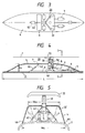
- FIG.3 through FIG.7 show detailed views of the current collector 20 and the containing dome 4 embodying the present invention.
- the current collector 20 Since the current collector 20 is not operated with folding structure which the conventional pantograph has, the current collector 20, as one unit consisting of a collector head 22, a support insulator 30 for insulation, a driving rod 31 for upward and downward driving, a cylinder 32 and a cable head 50 for current conduction, is rotated with a rotating system 40 around a horizontal axis and contained into the containing dome 4 when it is not in the current collecting condition. Therewith, the aerodynamic resistance and the noise during vehicle running can be decreased.
- the current collector 20 is arranged to be raised by a cylinder 7 for raising and lowering and a rod for raising and lowering 8 and to be rotated around an axis 40A of the rotating system 40.
- the rotating system 40 is supported with a fixed member 41 which is mounted on the base plate 3 on a car body 2.
- the shutter system 9 When the current collector 20 is raised or lowered, the shutter system 9 is opened with operation of a cylinder 42 for shutter and a rod 43 for shutter. When the current collector 20 is collecting current or is contained in the containing dome, the shutter system 9 is closed.
- a high voltage flexible cable 44 is heavily stressed and requires to be changed on schedule since it is frequently moved every time the current collector 20 is set. Therefore, a high voltage connector 6 is provided between the flexible cable 44 and the high voltage cable 5 buried in the car body 2 so as to make changing the high voltage flexible cable 44 easy
- drain holes 46 As the roof of the vehicle body 2 is, as shown in FIG.5, arc-shaped being convex upward, the drain is easily carried out through the drain holes 46 on the both side walls of the containing dome 4.
- contact strips 21 for current collecting are buried on the top of the collector head 22 having a delta-wing shape, and are pushed to the trolley wire 1 with contact strip pressing springs 23 and with a driving system which will be described later.
- the collector head 22 is secured to the top of the supporting insulator 30 for insulation with bolts, and the supporting insulator 30 for insulation is secured to a driving rod 31 positioned below and projecting from a driving cylinder 32.
- the numeral 33 is a load cell to detect the force acting between the driving rod 31 and the supporting insulator 30 for insulation, that is the reaction force to push up the collector head 22.
- the driving rod 31 is pushed up by means of hydraulic pressure produced with a hydraulic pressurizer separately installed in such a way that the contact pressure of the current contact strips 21 against the trolley wire 1 is controlled to become optimum.
- the collector head 22 has a nearly triangle wing shape when it is seen from above as shown in FIG. 8.
- the two ends in the width direction of the collector head 22 are bent down.
- the contact strips 21 a are secured to the collector head 22 with bolts such that the strips have the same potential as the collector head to prevent sparking.
- the bolts are positioned in the hollow parts in the contact strips to decrease projecting parts on the surface. There is no spring 23 between the contact strips 21 a and the collector head 22.
- the contact strips 21 and 21a are electrically connected to a conducting wire 51 a.
- a conductive member is provided between the contact strips 21 and 21 a and the conductive wire 51 a.
- the external surface of the connecting part of the supporting insulator 30 for insulation and the collector head 22 is arc-shaped. Thereby, the production of the aerodynamic noise generated in said portion is decreased.
- the longitudinal cross section of the collector head 22 is stream-line shaped the height of which lessens with going rear-ward as shown in FIG. 6.
- the material of the collector head 22 is aluminum in order to decrease its weight. It may be formed mainly with resin the surface of which is coated with GFRP or CFRP.
- the driving rod 31 for the driving cylinder 32 and the bottom portion of the supporting insulator 30 for insulation are connected through a unit of the load cell 33.
- the supporting insulator 30 for insulation and the driving rod 31 are connected to the unit for the load cell 33 by using the top and bottom flanges thereof.
- the bottom portion of the supporting insulator 30 for insulation is cylindrical, and the diameter of the supporting insulator 30 is the same as the diameter of the cylinder portion of the cylinder 32. This portion is covered with a sleeve 59.
- the sleeve 59 is longitudinally cut into halves which are fixed to the cylindrical portion of the supporting insulator 30 for insulation and the cylinder portion of the cylinder 32 from outer-ward of the radial direction using flat countersunk head screws.
- the length of the sleeve 59 is longer than the stroke of the driving rod 31.
- the corner of top end of the sleeve 59 is rounded.
- the driving rod 31 is a rod driven with oil-hydraulic pressure.
- the numeral 130 indicates a shutter to cover the surrounding of the sleeve 59, which will be described later.
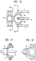
- the cable head 50 for current direction described above has the structure where the conductive element 53 penetrates the center of the insulator 52 in the axial direction.
- the top of the conductive element 53 projects from the insulating portion, and has a brace projecting side-ways fixed with bolts. Instead of this a protective cap may be attached to the portion as is well known.
- a high voltage flexible cable 44 is attached to the bottom end of the conductive element 53.
- the outer diameter of the cable head 50 for conduction is gradually decreasing toward its top, and the cable head 50 serves as a high voltage insulator.
- the brace on the top of the conductive element 53 and the collector head 22 are connected with a conductive wire 51 flexibly braided.
- the conductive element 51 is fixed with bolts and nuts.
- the conductive wire 51 is formed of a braided wire such that the collector head 22 may easily move upward and downward against the cable head 50 for conduction, and has at least one U-shaped turn in a part thereof.
- the U-shaped turn in the cable makes upward and downward moving easy even when the distance between the fixed ends of the conductive wire 51 is small.
- the cable head 50 for conduction is positioned at the back of the supporting insulator 30 for insulation, and the connecting positions of the conductive wire 51 with the collector head 22 and the conductive element 53 are also positioned at the back of the supporting insulator 30 for insulation.
- the insulator in the cable head 50 for conduction has, as shown in FIG.1 through FIG.12, an uneven portion in its surface, and its bottom portion 52 is columnar.
- the bottom of the column 52 is fixed to a base 55 from upper side with bolts.
- the base 55 and the cylinder portion of the cylinder 32 are formed in a single unit structure.
- There are flanges in the bottom of the cable head 50 for conduction and in the top of the base 55 which are connected together with a plurality of bolts.
- the connecting portions for cylinders 7 for raising and lowering in both sides of the base 55 there are connecting portions for cylinders 7 for raising and lowering in both sides of the base 55, the hollow space of which is penetrated by the connecting portion of the cable head 50 and the high voltage flexible cable 44.
- the extending direction of the cylinder 7 for raising and lowering is in the longitudinal direction of the vehicle.
- the cable 44 is positioned between the two cylinders 7.
- the cable 44 is connected to the cable 5 through the connector 6.
- the cable 44 is softer than the cable 5.
- the connector 6 has such a structure that connecting and disconnecting of the connector 6 and the cable 44 is comparatively easily carried out.
- the parts such as the driving cylinder 32, the connector 6, the cylinder 7 and so on, are mounted on the base plate 3 through the fixed member 41.
- the base plate 3 is fixed to a base formed in the roof of the vehicle itself with bolts. There is a cut part in the base plate 3 below the high voltage flexible cable 44 to make space for bending of the high voltage flexible cable 44 and to make bending of the high voltage flexible cable 44 at rotation of the supporting insulator 30 for insulation easy.
- the driving rod 31 does not affect the high voltage flexible cable 44.
- the driving rod 31 has a function to push the current collecting contact strip 21 to the trolley wire 1 with a desired pressure and moves up and down with high frequency
- the cable 44 is bent with the operation of the cylinder 7, the bending condition occurs substantially at the turn back operation and the frequency of bending is extremely small. Therefore, the long wearing life of the cable 44 can be achieved.
- the load cell 33 can detect the contact pressure with the trolley wire 1.
- the driving rod 31 Since there is the supporting insulator 30 for insulation between the driving rod 31 and the collector head 22, the driving rod 31 is not at high voltage. Therefore, an oil-hydraulic type can be applied to the driving cylinder 32, which improves response to the control signal.
- the sleeve 59 is positioned at the bottom end of the supporting insulator 30 for insulation and the gap between the supporting insulator 30 for insulation and the containing dome 4 can be made small, the inflow of rain, snow or air into the sleeve 59 can be prevented even though the diameter of the rod 31 at the bottom end of the support insulator 30 for insulation is small. Therefore, the length below the bottom end fold of the supporting insulator 30 can be made small.
- the sleeve 59 may be eliminated when the length of the column at the bottom end of the supporting insulator 30 for insulation is longer than the stroke of the driving rod 31.
- the shutter 110 is a shutter to close the opening through which the collector head 22 penetrates, and is formed in a piece of flat plate.
- the shutters 120 and 120 are shutters to cover the opening through which the supporting insulator 30 penetrates, and are divided in the width-direction of the vehicle into two portions to close one opening with a pair of flap type shutters.
- the shutters 130 are sliding type shutters to cover the opening where the insulator 30 and 52 is in the condition of raising upright, and are divided in the width-direction of the vehicle into two portions to close one opening with a pair of shutters.
- the shutter 140 is a sliding type shutter to close the same opening that the shutters 140 close when the current collector 20 is contained in the containing dome 4. At this time, the shutters 130 do not close the opening.
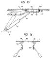
- the shutter 110 as shown in FIG.15, is of a sliding type, and is slid along the longitudinal direction of the vehicle.
- Each side of the shutter 110 is supported by the guide rails 115 through four rollers 112.
- the guide rails 115 guide the top, bottom and side of the rollers 112.
- the shutter 110 is positioned on the reverse side of the containing dome 4 when the opening is open, and is fitted in the opening when the opening is closed.
- the upper surface of the shutter 110 makes substantially the identical surface with the upper surface of the containing dome 4.
- the guide rails 115 have curves such as to move the shutter 110 as described above.
- a cylinder 42 for up- and downward driving is installed on the base plate 3.
- the shutters 120 are, as shown in FIG.16, opened and closed by turning with hinges 122 as turning axes.
- Cylinders 129 are installed on the base plate 3.
- the shutter 130 are of a sliding type as well as the shutter 110.
- the guide rails 135 for the shutters 130 are not installed in the side portion of the opening. The reason for this is to prevent crossing over with the shutter 140. Therefore, the portion of shutter to close the opening has no guide roller either.
- the shutter 130 In order to put guide rollers to the shutter 130, the shutter 130 has such a shape that the shutter largely extended toward the opposite side of running direction when the opening is opened. Cylinders 139 are installed on the base plate 3.
- the other structure for the shutters 130 is the same as the structure for the shutter 110.
- heaters 47 and 48 in the circumference of the shutters 110 and 120 of the containing dome 4.
- a heater may be provided at the portion where the shutters 120 contact each other, if necessary.
- the other shutters 130 and 140 also have heaters (not shown). When they freeze in winter season and the shutters 110, 120, 130 and 140 are opened after the heaters are supplied electric power to melt ice, the current collector 20 is easily raised and lowered.
- the shutter 140 are of a sliding type as well as the shutter 110.
- the guide rails 145 for the shutters 140 are not installed in the side portion of the opening. The reason is to prevent crossing over with the shutter 130. Therefore, the portion of shutter to close the opening has no guide roller either.
- the shutter 140 In order to put guide rollers to the shutter 140, the shutter 140 has such a shape that the shutter largely extended toward the opposite side of running direction when the opening is opened. Cylinders 149 are installed on the base plate 3.
- the other structure for the shutters 140 is the same as the structure for the shutter 110.
- the containing dome 4 is, as shown in FIG.17, partitioned into three, 4A, 4B, 4C.
- the containing dome 4A is the region from the guide rail 135 for the shutter 130 to the guide rail 115 for the shutter 110.
- the containing dome 4 has inspection hatches 4Aa, 4Bb, 4Cc on the side surface of the containing dome in an appropriate positions to be used for inspection, assembling and replacement of parts for the devices in the containing dome 4.
- the current collector 20 projecting upward from the containing dome 4 is, as shown in FIG.18 through FIG.20, contained in the containing dome 4 by driving the cylinder 7.
- the collector head 22 is slightly pulled down (approximately 100mm) to be detached from the trolley wire 1 as shown in FIG.18.
- the shutter 9 is opened, and the current collector 20 is lowered into the containing dome 4, and then finally the shutter 9 is closed.
- the current collector 20 composed of the collector head 22 and the driving cylinder 32 having the supporting insulator 30, the cylinder 7, the flexible cable 44 and the connector 6 are mounted on the base plate 3.
- the current collector 20 is in the dome 4 (FIG.14).
- the driving rod 31 is in the most reducing condition in its length.
- the top of the collector head 22 is set on a buffer base (not shown in figure) installed on the base plate 3.
- the cylinders 42, 129, 129, 139, 139, 149 are set in the base plate 3.
- the assembly is mounted on the roof of the vehicle 2 and the base plate 3 is fixed to the roof with bolts.
- the current collector 20 may be in the lowered condition.
- the cylinders 42, 129, 129, 139, 139, 149 may be also installed.
- the dome 4A is mounted on and fixed to the roof 2 with bolts.
- the shutters 110, 120, 120, 130, 130, 140 have been attached to the dome 4A in advance.
- the cylinders 42, 129, 129, 139, 139, 149 and the shutters 110, 120, 120, 130, 130, 140 are connected by the work through the inspection hatches.
- the end portions of the dome 4B and 4C are mounted on the roof and fixed to the roof 2 and the dome 4B.
- the connecting portion of the dome parts is of overlapping structure.
- the replacement of the cable 44 or the cable head 50 is carried out in such a manner that the dome 4 is removed in the condition where the current collector 20 is contained in the dome 4.
- the replacement work can be comparatively easily carried out since the opening 55a of the base 55 is directed upward and the connector 6 is provided.
- the cylinders 42, 129, 129, 139, 139 may be horizontally installed in the dome 4A. When this is done, the dome 4 may be formed as a unit. Further, the inspection hatches may be miniaturized. The cylinders 42, 129, 129, 139, 139 may be easily connected with the shutters and the dome 4. This assembling is carried out with the dome 4 turning upside down.
- the shutters 130 and 130 in the dome 4, where the sleeve 59 penetrates, are also stood upward in arc-shape.
- Each of the shutters 130 has two semi-circular openings.
- two holes are formed with closing the two shutters 130 and 130.
- the sleeve 59 and the insulator 52 penetrate these two holes.
- the holes have rubber buffers on their peripheries.
- the hole for the sleeve 59 is slightly larger than the other since the sleeve 59 moves upward and downward.
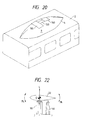
- FIG.21 shows horizontal sectional views of the supporting insulator 30 (30a, 30b, 30c) and the cable head 50, and relationships between air flow and the configuration.
- the figure (a) shows a combination where the round-shaped support insulator 30a for insulation has a slightly larger diameter than the diameter of the round-shaped cable head 50 (the aero-dynamic diameters are nearly the same), and they are placed back and forth in thee stream.
- the air flow mainly hits the support insulator 30 which is placed the front side of the running direction, the turn back air hits the cable head 50 for conduction to produce noise in some cases.
- the figure (b) shows a combination where the support insulator 30b has a slightly larger diameter d1 than the diameter D1 of the cable head 50.
- the air flow mainly hits the support insulator 30 which has a large diameter and is placed the front side of the running direction, and the air does not hit the cable head 50. This decreases noise.
- the figure (c) shows a combination where the support insulator 30c is formed to have a wide width perpendicular to the air flow and have a nearly stream-line shape, and the cable head 50 is actively hidden in the shade of the supporting insulator 30. When this is done, the noise decreases more than the case (b). It is desirable that the diameter or width of the supporting insulator 30 is, as described above, larger than the diameter of the cable head 50.
- the supporting insulator 30 is made of epoxy resin.
- the distance L between the two insulators 30 and 50 is determined from the low noise point of view. It is thought that interference of two noises may lower the noise.
- the diameters of the supporting insulator 30 are the same from the top to the bottom (above the dome 4), the diameters may be varied, for example, such as to increase as goes downward. When this is done, it is expected that the noise may be lowered since the air flow varies in the vertical direction.
- the supporting insulator 30 is placed just below the center of gravity G of the collector head 22, that is the position on which the weight of said collector head 22 acts and the lift force L caused by the air flow hitting the collector head acts.
- a lift force L acts on the collector head 22 during vehicle running.
- the vertical sectional shape of the collector head 22 is symmetric to upside and downside, the velocity in the downside thereof is lower than the velocity of the upside thereof since said supporting insulator 30 for insulation is installed. Therefore, the lift force acting in said collector head 22 acts upward.
- the position of the lift force acting on the collector head 22 is the position of center of gravity G and said supporting insulator 30 for insulation is installed corresponding to the position, the angular moment ML shown in the figure is not caused. This means that no excessive force acts on the supporting insulator 30.
- the acting position of the center of gravity G of the collector head 22 agrees with the acting position of the lift force of the collector head 22. In a case where it is hard to agree the position of the center of gravity G with the acting position of the lift force, consideration is required to make them as close as possible.
- the dome 4 may cause upward turning of the air flow.
- the collector head 22 may be tilted so as to match the angle of the air flow, or the collector head 22 may be moved to a place where there is no effect of the angle of air flow caused by the dome 4. Therein, it is desirable that the angle and the movement of the collector head 22 are adjusted corresponding to the speed of the vehicle.
- FIG.23 shows an application of the present invention to a train of vehicles.
- the vehicles 2 (2A - 2H) are running from the right hand side to the left hand side as shown by an arrow.
- current collection is carried out by a vehicle in the rear of the train in order to decrease aero-dynamic resistance and to lower noise by means of placing the current collector 20 in a place where boundary layer more develops. Therefore, in the figure, the two current collectors (20F, 20H) in the rear are raised, and the two current collectors (20A, 20C) in the front are contained in the domes 4.
- the electricity collected with the current collector 20 is directed to a high voltage unit box 60 through a high voltage connector 6 and a high voltage cable 5.
- a vacuum circuit breaker 61 for receiving and a vehicle vacuum circuit breaker 62 which are connected with a cable head 68 for current conduction and a high voltage take-out cable 67 respectively.
- the vacuum circuit breaker 61 prevents the current collector 20 lowered and out of use from application of high voltage with other current collectors 20 through the high voltage take-out cable 67.
- the vacuum circuit breaker 62 switches on and off current circuit to current collector 20 installed in each vehicle.
- the current passed through the vacuum circuit breaker 62 in such a way is dropped in voltage with a main transformer 63, then the current is converted with a main convertor 64 into three phase alternating current and its frequency and voltage are controlled corresponding to the speed and the traction force of the vehicle to drive a main motor 65.
- the current after driving the main motor 65 returns to a rail 69 through a wheel and axle 66.
- a high voltage switch 61 cuts off high voltage from the current collector 20 at the time when the current collector 20 is lowered.
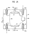
- FIG.24 shows an example of the arrangement of units in the high voltage unit box 60.
- the vacuum circuit breaker 61 and the vacuum circuit breaker 62 are installed in the top and the bottom of the box 60.
- Bare wires 68a are used for connections among both of the vacuum circuit breakers 61, 62 and the insulators for take-out 68aa, 68ab, 68ac, 68ad.
- the vacuum circuit breakers 61 and 62 known in the art switch on and off the current circuit with flowing current to magnetic coils 61 a and 62a.
- a cable 68aa is used for connecting to the high voltage flexible cable 44, a cable 68ab being used for connecting to the main transformer 63, cables 68ac and 68ad being used for connecting to the other unit boxes 60.
- the numeral 68A indicates an arrester which is connected to the vacuum circuit breaker 62.
- the vacuum circuit breakers 61 and 62 have the same specification. Since the vacuum circuit breaker 61 is installed under the floor of the vehicle, the center of gravity of the vehicle can be lower than when it is installed on the roof. Further, the two vacuum circuit breakers 61 and 62 are installed in one unit box 60, which also leads to low cost.
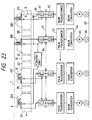
- Each vehicle in a train of vehicles has a control unit 84 having the following structure as shown in FIG.25. Since the train has four current collectors 20 (20A, 20C, 20F, 20H), the control unit 84 controls four sets.
- the set is composed of one vacuum circuit breaker 61, one driving cylinder 32, two cylinders 7 and six cylinders 42, 129, 129, 139, 139, 149.
- the control unit 84 includes a memory 84A, a CPU 84B, an input/output interface 84C.
- the CPU 84B executes the program stored in the memory 84A, and executes various kinds of processing.
- the CPU 84B When the switch 9Dl for instructing which vehicle in the train is the front vehicle is switched on, the CPU 84B, as shown in FIG.26, outputs a lower command (262) to the two current collectors (20A, 20C) in the front side of the train and sends a raising command (264) to the two current collectors (20F, 20H) in the rear side.
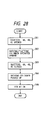
- the operating procedure on the lower command is as shown in FIG.27.
- the vacuum circuit breaker 61 is cut off (271) to prevent sparking.
- the driving rod 31 is lowered up to the lowermost position to realize the condition in FIG.18 (272).
- the shutters 110, 120, 120, 130, 130 are opened by the cylinders 42, 129, 129, 139, 139 (273).
- the current collector 20 is lowered in the containing dome 4 using the cylinder 7 as shown in FIG.19 (274).
- the shutters 110, 120, 120, 140 are closed by the cylinders 42, 129, 129, 149 (275).
- the operation timings of the cylinders 129 and 129 are different each other.
- the current collector 20 is capable of being rotated by a small power since it is rotated after being lowered by the driving rod 31 to be detached from the trolley wire 1. Further, lowering the current collector 20 makes the length of the shutters 120 and 120 short and also makes the length of the containing dome 4 short.
- a link mechanism may be installed between the insulator 30 and the driving cylinder 32 instead of using the driving rod 31 to move the insulator 30 upward and downward directly When this is done, the driving cylinder 32 may be used also for serving the cylinder 7.
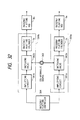
- FIG.29 through FIG.31 show a structure of the collector head driving system 230 for pushing force control of the current collector 20.
- a load cell 33 for control and a displacement meter 34 are inserted between the supporting insulator 30 and the driving rod 31.
- the outputs from the load cell 33 and the displacement meter 34 are lead to a control unit 83 together with the output information from a speed information detector 85 and a railway information detector 86, and the control unit 83 calculates the optimum contact pressure against the trolley wire 1 and transfers an electric signal to a servo amplifier 242 in a servo control device 240.
- a servo valve 243 receives the electric signal from the servo amplifier 242 and controls the liquid flow from a oil-hydraulic source 241 with the electric signal to control the push-up force u between the driving cylinder 32 and the driving rod 31.
- the servo control device 240 operates the driving cylinder 32 and the driving rod 31 with a control signal r from a control unit 83 to apply a push-up force u to the collector head 22, the support insulator 30 and so on.
- the control unit 83 is installed on the earth side (electric potential is zero) in the pantograph dome 4 in the roof of the vehicle 2.
- the control unit 83 inputs a fluctuating force signal fx and a vertical displacement signal y 3 to a contact force observer unit 233.
- the signals are obtained through amplifying the output signals from a load cell 33 for controlling and a displacement meter 34 which are installed between the support insulator 30 for insulation 30 and the driving rod 31, using a detected signal checking circuit 253.
- control signal r is fed at the same time to the contact force observer unit 233. Then the contact force observer unit 233 outputs with estimation a contact force estimated signal f A and a disturbance suppressing force estimated signal fa ⁇ .
- the contact force observer unit 233 is composed of a state value estimating unit 236, a disturbance suppressing force gain unit 237 and a contact force estimating unit 238.
- the k 2 is a normal compensating gain in the normal difference compensating unit 232.
- the load cell 33 is installed between the support insulator 30 and the driving rod 31, and detects the load, either tension or compression, with high accuracy to output a fluctuating force signal fx acted.
- the displacement meter 34 is installed between the supporting insulator 30 and the driving cylinder 32, and outputs the vertical displacement, the velocity and acceleration of the driving rod 31.
- the lift force mainly acts on the collector head 22, the supporting insulator 30 and so on, and consists of the resultant lift force fq of average lift force and fluctuating lift force acting vertically. Therefore, when the vehicle runs at a high speed, the fq acting on the total body of the current collector 20 increases, and accordingly the contact pressure f substantially varies.
- Said contact pressure is expressed with an equation (Equation 1). wherein, the y 1 , y 1 ', y 1 '' are the displacement, the velocity and the acceleration of the current collector contact strip 21 and so on.
- the y 3 , y 3 ', Y 3 " are the displacement, the velocity and the acceleration of the collector head 22, the supporting insulator 30 and so on.
- the target value command unit 231 sets with optimizing and varying the contact pressure target value f * by using the running information (running speed, running route, position, weather, running time, earthquake etc.) transferred from a vehicle controller.
- the control signal r which is obtained by subtracting the disturbance lift pressure estimated signal fa from the Q through a subtractor, is input to the servo control device 240.
- the driving rod 31 is operated using the control signal r so as to suppress the lift force fq and the external force from the trolley wire 1.
- the disturbance suppressing force gain unit 237 multiples the following weight functions of the disturbance compensating gains k 1 '(a i - a 8 ) to the output signals (y 1 , y 3 , y' 1 , y' 3 , z, z', z", z"') from the state value estimating unit 236 which contains the lift force fq and the external force from the trolley wire 1.
- the z, z', z", z"' are the displacement, the velocity, the acceleration and the acceleration ratio of the convex and concave of the trolley wire 1.
- the contact force estimating unit 238 calculates the contact force estimated signal f ⁇ (the equation (Equation 3)) using the output signals P (y 1 , y 3 , y' 1 , y' 3 , z, z', z", z"') from the state value estimating unit 236.
- the a is an equivalent mass of the trolley wire 1
- the b is an equivalent damping factor of the trolley wire 1.
- the k 1 is the spring constant of the pushing spring 23 for the contact strip
- the c 1 is the damping coefficient of the pushing spring 23 for the contact strip
- k 1 " is the contact force gain.
- the P is an estimated state value of observer (y 1 ⁇ , y 3 ⁇ , y' 1 ⁇ , y' 3 ⁇ , z ⁇ , z' ⁇ , z" ⁇ , z"' ⁇ ), the F x being an input scalar to the force detector, the A being an 8x8 matrix, the L A being a 1 x8 vector, the C being a 1 x8 vector, the B being a 8xl vector.
- the seven observer characteristic roots of the state value estimating unit 236 are determined on the complex coordinate in such a manner as follows. That is to determine the roots of the matrix (A-L A C) in the equation (Equation 4).
- the X is a state value (y 1 , Y3 , y' 1 , y' 3 , z, z', z", z"') vector
- the H being a vector constant
- the f being an output scalar for the contact force
- the W being an input scalar of the disturbance
- the A being an 8x8 matrix
- the B being an 8 ⁇ 1 vector
- the C being a 1x8 vector
- the D being an 8 ⁇ 1 vector
- the D being a 1x8 vector.
- the k 2 is the normal compensating gain vector
- the Q is an output state value (1 ⁇ 1) vector of the normal difference compensating unit 232
- the F being a scalar constant
- the G being a vector constant
- the (f *- f A ) being an input scalar to the force difference value control signal.
- the contact force can be decreased with inputting said control signal r for the pushing-up force u (Equation 8) based on fa A and f A to the servo control device 240, the fa and the f are obtained through inputting said control signal of the varying force signal fx and the push-up force u to the contact force observer unit 233.
- the disturbing compensating gain k 1 ', the vector constant H and the normal compensating vector F/G used in this time are required to select properly.
- FIG.31 shows a structure of the current collector driving system 244 which is input said control signal r to output the pushing-up force u.
- the system 244 is composed of an amplifying circuit 242 to amplify said control signal r, a servo valve 243 to control the oil pressure from an oil-hydraulic pressure source 241, a driving cylinder 32 and a driving rod 31 to produce the pushing-up force u by the action of expansion and contraction operation caused by the servo valve 243.
- an oil-hydraulic pressure source 241 is used in this example, a compressed air source may be used, as described later, instead when the response of the servo valve and cylinder is fast enough. In this case, the transfer characteristic of the pushing-up force u corresponding to said control signal r is required, to be the same order.
- FIG.32 is a block diagram showing the operation of the two containing systems 360a and 360b to contain the collector head 22 in the containing dome 4, wherein the two rods 8a and 8b for raising and lowering are operated to expand and contract and the collector 20 is operated to rotate through the rotating system 40.
- the two containing systems 360a and 360b are composed of amplifiers 361a a and 361 b, switching valves 362a and 362b, cylinders 7a and 7b for raising and flatting.
- the containing systems When the containing systems are input the operation signal from the controller 364 for raising and lowering installed in the containing dome 4, the containing systems are operated with oil-hydraulic pressure from the oil-hydraulic pressure source 363 to raise the current collector 20 perpendicular to the car body 2 with the rods 8a and 8b for raising and lowering, as shown in FIG.18, so as to collect current from the trolley wire 1.
- the containing system disconnect the contact strip from the trolley wire 1 to contain in the containing dome 4 with projecting the rods 8a and 8b as shown in FIG.19.
- Another embodiment of the present invention may be realized with use of motors for driving the current collector 20 instead of oil-hydraulic pressure.
- the shutter system for the containing dome 4 is not required. Since the containing dome 4 itself has a substantial effect to decrease noise, the opening, through which the current collector 20 is put out or into, may be kept open.
- FIG.33 shows a further embodiment of the present invention where a high voltage flexible cable 44 for current conducting is held in the hollow portion of the supporting insulator 30.
- a conductor 53 is installed in the inside of the insulator to support a collector head 22.
- a cable head for current conduction supports the collector head 22.
- the cable 44 is drawn out of the side of the insulator 30.
- the collector head 22 is fixed with a nut and a screw which is formed on the top end of the current conductor in the cable head 22 for current conduction.
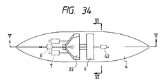
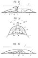
- FIG.34 - FIG.37 show a further embodiment of the present invention.
- the current collector 20 is rotatably lowered rearward in the running direction.
- a high voltage flexible cable 44 is positioned between the branches of a hinge supporting the current collector 20.
- the domes 4A, 4B, 4C are inversely positioned in the running direction relative to the embodiments described above.
- the size of the containing dome 4 can be miniaturized comparing to the embodiments described above, which decreases the running resistance.
- the supporting insulator 30 is kept standing upright during running in the above embodiments, it is thought that its tilting angle may be varied corresponding to the running speed by operation of the cylinders 7 for raising and lowering to control the wing force.
- the collector head 22 Since the lift force acts on the collector head 22 during high speed running, the collector head 22 is controlled such that the top front of the collector head 22 is directed slightly downward using the cylinder 7.
- the controller 364 operates the cylinder 7 such that the top front of the collector head 22 is directed slightly downward when the vehicle runs faster than a given running speed using the running speed information from a controller on vehicle. And the command from a central operation room is also used.
- the collector head 22 Since the lift force becomes large when the vehicle is passing another vehicle in a tunnel, the collector head 22 is similarly directed downward. When the vehicle enters into a tunnel at a high speed, the collector head 22 is also directed downward.
- the controller 364 operates the cylinder 7 using the running position information from the controller on vehicle or the command from the central operation room.
- baffle plate is placed at the back of the cable head for current conduction 50 to straighten air flow downstream of the cable head 50.
- the baffle plate is made of insulator and attached to the mounting base 55 for the cable head 50.
- an emergency ground switch EGS 300 is installed parallel to the cable head 50 in the current collector 20.
- the emergency ground switch EGS has a copper rod 303 driven with cylinder mechanism 302 operated by a compressed air source 301.
- the copper rod 303 which is normally in the dome, is projected from the dome by a drivers emergency operation to connect its upper end to the collector head 22 through a clip 304 as shown in the figure.
- the numeral 305 indicates a braided copper wire connected to the base plate 3.
- the emergency ground switch EGS has the function to shunt the vicinity of the collector head 22 to the ground as fast as possible at an emergency
- the emergency ground switch EGS, cylinder mechanism 302 of which is formed with the cylinder 32 as a unit, is rotated to raise or lower together with the supporting insulator 30 and the cable head 50 for current conduction by the rotating system 40.
- the cable head 50 for current conduction is installed with having a tilt to make the high voltage cable easily movable.
- the cable head 50 for current conduction is not parallel to the support insulator 30 for insulation, which decreases standing wave produced between them and thus further decreases noise.
- a part of the structure having current collecting function can be light in weight and small in size and can improve control characteristic to follow to the trolley wire 1, since the part of the structure having current collecting function, which comprises the current collecting member and the driving system, is installed with being divided from a part of the structure having power current conducting function, which can, further, keep the power current collecting function sufficiently
- the generation of noise during a vehicle running can be suppressed since there is provided a containing system on the roof of the vehicle inside of which the driving system is always contained and the part of the structure having current collecting function together with the part of the structure having power current conducting function is contained when it is not collecting.
Claims (4)
Applications Claiming Priority (6)
| Application Number | Priority Date | Filing Date | Title |
|---|---|---|---|
| JP34795592A JP3150465B2 (ja) | 1992-12-28 | 1992-12-28 | 集電装置 |
| JP347955/92 | 1992-12-28 | ||
| JP26500/93 | 1993-02-16 | ||
| JP2650093A JPH06245308A (ja) | 1993-02-16 | 1993-02-16 | アクティブ制御付集電装置 |
| JP5099822A JPH06315202A (ja) | 1993-04-26 | 1993-04-26 | 高速低騒音集電装置及び集電方法 |
| JP99822/93 | 1993-04-26 |
Publications (3)
| Publication Number | Publication Date |
|---|---|
| EP0605214A2 EP0605214A2 (de) | 1994-07-06 |
| EP0605214A3 EP0605214A3 (en) | 1994-08-24 |
| EP0605214B1 true EP0605214B1 (de) | 1997-11-19 |
Family
ID=27285433
Family Applications (1)
| Application Number | Title | Priority Date | Filing Date |
|---|---|---|---|
| EP93310491A Expired - Lifetime EP0605214B1 (de) | 1992-12-28 | 1993-12-23 | Geräuscharmer Stromabnehmersatz hoher Geschwindigkeit |
Country Status (6)
| Country | Link |
|---|---|
| US (3) | US5531301A (de) |
| EP (1) | EP0605214B1 (de) |
| KR (1) | KR940013984A (de) |
| CN (1) | CN1090538A (de) |
| DE (1) | DE69315316T2 (de) |
| TW (1) | TW247302B (de) |
Cited By (1)
| Publication number | Priority date | Publication date | Assignee | Title |
|---|---|---|---|---|
| DE102015122221A1 (de) | 2015-12-18 | 2017-06-22 | Bombardier Transportation Gmbh | Verfahren zum Betreiben eines Schienenfahrzeugs |
Families Citing this family (37)
| Publication number | Priority date | Publication date | Assignee | Title |
|---|---|---|---|---|
| JPH0865808A (ja) * | 1994-08-19 | 1996-03-08 | Hitachi Ltd | 集電方法および集電装置 |
| DE29508707U1 (de) * | 1995-05-24 | 1996-09-26 | Siemens Ag | Elektrisch angetriebenes Fahrzeug |
| DE19524708C2 (de) * | 1995-07-10 | 2000-01-05 | Deutsch Zentr Luft & Raumfahrt | Stromabnehmer für ein Fahrzeug, insbesondere für ein Schienenfahrzeug |
| DE19529068A1 (de) * | 1995-08-08 | 1997-02-13 | Abb Patent Gmbh | Stromabnehmer |
| US5954171A (en) * | 1996-08-05 | 1999-09-21 | Abb Patent Gmbh | Moving contact |
| DE10007287B4 (de) * | 2000-02-17 | 2010-01-28 | Stemmann-Technik Gmbh | Verfahren zur Regelung der Kontaktkraft zwischen Stromabnehmer und Fahrdraht |
| GB0014752D0 (en) * | 2000-06-17 | 2000-08-09 | Alstom | Improvements in electric trains |
| KR20020077296A (ko) * | 2002-08-21 | 2002-10-11 | 권은기 | 전차선t-bar 탈락장치 |
| US20080110713A1 (en) * | 2006-11-10 | 2008-05-15 | Mining Technologies International (Mti) | Gravity biased constant response pantograph |
| GB2461515A (en) * | 2008-07-01 | 2010-01-06 | Tyco Electronics Ltd Uk | Pneumatic insulating device |
| US7758094B2 (en) * | 2008-09-11 | 2010-07-20 | Bullis James K | Two part automobile |
| JP4940314B2 (ja) * | 2010-01-15 | 2012-05-30 | 株式会社タカラトミー | 自動車玩具 |
| FR2955304B1 (fr) * | 2010-01-19 | 2014-06-20 | Alstom Transport Sa | Vehicule ferroviaire et procede de fabrication correspondant |
| CN101791934A (zh) * | 2010-03-09 | 2010-08-04 | 合肥博普高新科技有限公司 | 电动或太阳能公铁两用汽车及其线路 |
| IT1402945B1 (it) * | 2010-11-30 | 2013-09-27 | Contact S R L | Sistema di comando controllo attivo e diagnostico per pantografo ferroviario. |
| CN102108994B (zh) * | 2011-01-13 | 2013-10-16 | 太原理工大学 | 具有快速抑制冲击载荷的电液位置伺服系统 |
| DE102011082516B4 (de) | 2011-09-12 | 2019-09-05 | Siemens Mobility GmbH | Schienenfahrzeugsverband |
| US8944227B2 (en) * | 2011-11-02 | 2015-02-03 | Caterpillar Inc. | End horns for pantograph assembly |
| JP6208454B2 (ja) * | 2013-04-01 | 2017-10-04 | 日本車輌製造株式会社 | 鉄道車両用集電装置 |
| CN105339203B (zh) * | 2013-06-20 | 2018-10-19 | 沃尔沃卡车集团 | 用于电动车辆的保护设备 |
| DE102013226356A1 (de) * | 2013-10-02 | 2015-04-02 | Scania Cv Ab | Fahrzeug |
| CN104494619B (zh) * | 2014-12-08 | 2019-07-23 | 董兰田 | 上下双向导流动车头车 |
| US9937799B2 (en) * | 2015-10-23 | 2018-04-10 | Caterpillar Inc. | Pantograph down stop for trolley |
| CN105620294B (zh) * | 2016-03-21 | 2018-02-02 | 北京科技大学 | 一种无轨公交电车智能搭线方法及装置 |
| EP3538395A1 (de) * | 2016-11-10 | 2019-09-18 | Volvo Truck Corporation | Stromkollektor für ein fahrzeug |
| DE102017203510A1 (de) | 2017-03-03 | 2018-09-06 | Siemens Aktiengesellschaft | Stromabnehmer mit Ausgleichskontakten |
| DE102017215340A1 (de) * | 2017-09-01 | 2019-03-07 | Siemens Aktiengesellschaft | Verfahren zur Überprüfung einer Kontaktierung eines Stromabnehmers sowie Stromabnehmer |
| RU181784U1 (ru) * | 2017-12-12 | 2018-07-26 | Федеральное государственное бюджетное образовательное учреждение высшего образования "Петербургский государственный университет путей сообщения Императора Александра I" | Токоприёмник для электроподвижного состава |
| CN111231682B (zh) * | 2018-11-29 | 2021-11-12 | 比亚迪股份有限公司 | 充电系统 |
| CN111907334A (zh) * | 2019-06-18 | 2020-11-10 | 中车大同电力机车有限公司 | 受电弓及其控制方法、电力机车 |
| CN112297851B (zh) * | 2019-07-31 | 2022-05-13 | 比亚迪股份有限公司 | 轨道车辆的授流装置和轨道车辆 |
| CN112440749B (zh) * | 2019-08-29 | 2022-06-14 | 比亚迪股份有限公司 | 轨道车辆的充电系统及具有其的轨道交通系统 |
| CN110548304A (zh) * | 2019-09-07 | 2019-12-10 | 天津药明康德新药开发有限公司 | 用于移除沸点溶剂的离心浓缩仪 |
| DE102019126262A1 (de) * | 2019-09-30 | 2021-04-01 | Bombardier Transportation Gmbh | Stromabnehmeranordnung für schienenfahrzeuge |
| CN112763180B (zh) * | 2021-04-08 | 2021-07-09 | 中国空气动力研究与发展中心低速空气动力研究所 | 声学风洞内高速列车受电弓模型气动噪声快速预测方法 |
| CN113978496B (zh) * | 2021-12-10 | 2022-12-20 | 中南大学 | 高速列车受电弓区域全封闭式导流装置 |
| US20240101344A1 (en) * | 2022-09-27 | 2024-03-28 | Transportation Ip Holdings, Llc | Equipment asset with liquid runoff charge control |
Family Cites Families (27)
| Publication number | Priority date | Publication date | Assignee | Title |
|---|---|---|---|---|
| US523104A (en) * | 1894-07-17 | butler | ||
| US1237247A (en) * | 1916-11-13 | 1917-08-14 | Alexander Englund | Trolley-shoe. |
| US2824911A (en) * | 1953-12-03 | 1958-02-25 | Ashton B Taylor | Collector shoe and conductor bus bar |
| US2999334A (en) * | 1957-08-15 | 1961-09-12 | Lionel Corp | Locomotive pantograph |
| FR1400376A (fr) * | 1963-10-24 | 1965-05-28 | Faiveley Sa | Perfectionnement aux dispositifs de prise de courant pour grandes vitesses ferroviaires |
| US3405240A (en) * | 1967-01-04 | 1968-10-08 | Insul 8 Corp | Mobile electrification collector head |
| DE1903746A1 (de) * | 1969-01-25 | 1970-08-20 | Siemens Ag | Elektrisches Triebfahrzeug mit Stromabnehmer fuer dritte Schiene |
| DE2522876A1 (de) * | 1975-05-23 | 1976-12-09 | Stemmann Ohg A | Verfahren zur regelung der fahrdraht- anpresskraft von stromabnehmern schnellfahrender elektrischer triebfahrzeuge |
| AT357606B (de) * | 1977-07-12 | 1980-07-25 | Siemens Ag Oesterreich | Vertikalgefuehrter hochgeschwindigkeits-strom- abnehmer |
| AT352181B (de) * | 1977-07-22 | 1979-09-10 | Siemens Ag Oesterreich | Einrichtung zur verstellung der auftriebs- steuerklappe fuer einen vertikalgefuehrten hoch- geschwindigkeits-stromabnehmer |
| US4116312A (en) * | 1977-09-28 | 1978-09-26 | Permali, Incorporated | Mine vehicle trolley pole |
| DE2753932A1 (de) * | 1977-11-11 | 1979-05-17 | Bbc Brown Boveri & Cie | Stromabnehmer fuer trolleyfahrzeuge |
| US4510352A (en) * | 1982-08-19 | 1985-04-09 | Consolidation Coal Company | Trolley pole |
| SU1271771A1 (ru) * | 1985-05-22 | 1986-11-23 | Омский Институт Инженеров Железнодорожного Транспорта | Токоприемник |
| DE3536843A1 (de) * | 1985-10-16 | 1987-04-16 | Dornier System Gmbh | Stromabnehmervorrichtung |
| FR2600287B2 (fr) * | 1985-11-20 | 1988-10-21 | Delachaux Sa | Tete de trolleybus |
| US4908747A (en) * | 1988-03-21 | 1990-03-13 | The Babcock & Wilcox Company | Advanced proportional plus integral plus derivative controller |
| DE3828889C2 (de) * | 1988-08-25 | 1997-10-02 | Dozler Gmbh | Stromabnehmer |
| FR2646381B1 (fr) * | 1989-04-28 | 1991-07-26 | Faiveley Sa | Dispositif pour regler la force d'appui d'un pantographe sur un fil catenaire et procede s'y rapportant |
| JPH0549104A (ja) * | 1991-08-08 | 1993-02-26 | Hitachi Ltd | 集電装置 |
| JPH0549103A (ja) * | 1991-08-08 | 1993-02-26 | Hitachi Ltd | 低騒音型集電装置 |
| JPH0568304A (ja) * | 1991-09-09 | 1993-03-19 | East Japan Railway Co | チエムニパンタグラフ |
| JPH05130706A (ja) * | 1991-10-31 | 1993-05-25 | Shimadzu Corp | 鉄道車両用集電装置 |
| JPH05146004A (ja) * | 1991-11-25 | 1993-06-11 | Hitachi Ltd | 集電装置 |
| JPH05176403A (ja) * | 1991-12-25 | 1993-07-13 | Shimadzu Corp | 鉄道車両用集電装置 |
| JPH0622404A (ja) * | 1992-07-03 | 1994-01-28 | West Japan Railway Co | 鉄道車両用集電装置 |
| JPH0622406A (ja) * | 1992-07-03 | 1994-01-28 | West Japan Railway Co | 鉄道車両用集電装置 |
-
1993
- 1993-12-23 DE DE69315316T patent/DE69315316T2/de not_active Expired - Fee Related
- 1993-12-23 EP EP93310491A patent/EP0605214B1/de not_active Expired - Lifetime
- 1993-12-27 TW TW082111031A patent/TW247302B/zh active
- 1993-12-28 US US08/174,280 patent/US5531301A/en not_active Expired - Fee Related
- 1993-12-28 CN CN93121488A patent/CN1090538A/zh active Pending
- 1993-12-28 KR KR1019930030199A patent/KR940013984A/ko not_active Application Discontinuation
-
1995
- 1995-04-20 US US08/425,467 patent/US5584369A/en not_active Expired - Fee Related
- 1995-04-20 US US08/425,612 patent/US5566800A/en not_active Expired - Fee Related
Cited By (1)
| Publication number | Priority date | Publication date | Assignee | Title |
|---|---|---|---|---|
| DE102015122221A1 (de) | 2015-12-18 | 2017-06-22 | Bombardier Transportation Gmbh | Verfahren zum Betreiben eines Schienenfahrzeugs |
Also Published As
| Publication number | Publication date |
|---|---|
| TW247302B (de) | 1995-05-11 |
| DE69315316T2 (de) | 1998-03-19 |
| DE69315316D1 (de) | 1998-01-02 |
| EP0605214A3 (en) | 1994-08-24 |
| US5584369A (en) | 1996-12-17 |
| US5566800A (en) | 1996-10-22 |
| US5531301A (en) | 1996-07-02 |
| EP0605214A2 (de) | 1994-07-06 |
| KR940013984A (ko) | 1994-07-16 |
| CN1090538A (zh) | 1994-08-10 |
Similar Documents
| Publication | Publication Date | Title |
|---|---|---|
| EP0605214B1 (de) | Geräuscharmer Stromabnehmersatz hoher Geschwindigkeit | |
| US5845581A (en) | Monorail system | |
| US6239362B1 (en) | Device for compensating variations in the length of tensioned cables, with substantially constant traction | |
| JPH0865808A (ja) | 集電方法および集電装置 | |
| CN105067158B (zh) | 一种弓网分离式受电弓压力检测装置 | |
| JPH06315202A (ja) | 高速低騒音集電装置及び集電方法 | |
| JP2000513919A (ja) | 集電装置と架線の間の接触力の変動を低減する装置 | |
| JPH07147703A (ja) | 高速低騒音集電装置及び集電方法 | |
| JP4513114B1 (ja) | 鉄道車両用集電装置 | |
| JPH06315203A (ja) | 高速低騒音集電装置及び集電方法 | |
| JP4386253B2 (ja) | パンタグラフ装置 | |
| JP2002325305A (ja) | 低騒音集電装置 | |
| JPH10248111A (ja) | 集電装置 | |
| JPH09252502A (ja) | 集電装置 | |
| JPH07123505A (ja) | アクティブ制御付集電装置 | |
| CN113581025A (zh) | 一种轨道车辆试验台用摆臂式接触网系统 | |
| JPH08205310A (ja) | パンタグラフ器の姿勢制御装置 | |
| JPS586363B2 (ja) | 走行体の集電装置 | |
| JPH09193798A (ja) | 高速車両用空力制動装置 | |
| JP2697509B2 (ja) | 集電装置 | |
| JP3622999B2 (ja) | 鉄道用集電装置 | |
| JP3396103B2 (ja) | パンタグラフ | |
| Coffey et al. | Preliminary design for a Maglev development facility | |
| JPH07107610A (ja) | アクティブ制御付集電装置 | |
| JPH07255101A (ja) | 集電装置 |
Legal Events
| Date | Code | Title | Description |
|---|---|---|---|
| PUAI | Public reference made under article 153(3) epc to a published international application that has entered the european phase |
Free format text: ORIGINAL CODE: 0009012 |
|
| PUAL | Search report despatched |
Free format text: ORIGINAL CODE: 0009013 |
|
| 17P | Request for examination filed |
Effective date: 19940112 |
|
| AK | Designated contracting states |
Kind code of ref document: A2 Designated state(s): DE FR |
|
| AK | Designated contracting states |
Kind code of ref document: A3 Designated state(s): DE FR |
|
| 17Q | First examination report despatched |
Effective date: 19951023 |
|
| GRAG | Despatch of communication of intention to grant |
Free format text: ORIGINAL CODE: EPIDOS AGRA |
|
| GRAH | Despatch of communication of intention to grant a patent |
Free format text: ORIGINAL CODE: EPIDOS IGRA |
|
| GRAH | Despatch of communication of intention to grant a patent |
Free format text: ORIGINAL CODE: EPIDOS IGRA |
|
| GRAA | (expected) grant |
Free format text: ORIGINAL CODE: 0009210 |
|
| AK | Designated contracting states |
Kind code of ref document: B1 Designated state(s): DE FR |
|
| REF | Corresponds to: |
Ref document number: 69315316 Country of ref document: DE Date of ref document: 19980102 |
|
| ET | Fr: translation filed | ||
| PLBE | No opposition filed within time limit |
Free format text: ORIGINAL CODE: 0009261 |
|
| STAA | Information on the status of an ep patent application or granted ep patent |
Free format text: STATUS: NO OPPOSITION FILED WITHIN TIME LIMIT |
|
| 26N | No opposition filed | ||
| PGFP | Annual fee paid to national office [announced via postgrant information from national office to epo] |
Ref country code: FR Payment date: 20001122 Year of fee payment: 8 |
|
| PGFP | Annual fee paid to national office [announced via postgrant information from national office to epo] |
Ref country code: DE Payment date: 20010220 Year of fee payment: 8 |
|
| PG25 | Lapsed in a contracting state [announced via postgrant information from national office to epo] |
Ref country code: DE Free format text: LAPSE BECAUSE OF NON-PAYMENT OF DUE FEES Effective date: 20020702 |
|
| PG25 | Lapsed in a contracting state [announced via postgrant information from national office to epo] |
Ref country code: FR Free format text: LAPSE BECAUSE OF NON-PAYMENT OF DUE FEES Effective date: 20020830 |
|
| REG | Reference to a national code |
Ref country code: FR Ref legal event code: ST |