EP0605206A2 - Méthode d'enregistrement de données et appareil d'enregistrement de données - Google Patents
Méthode d'enregistrement de données et appareil d'enregistrement de données Download PDFInfo
- Publication number
- EP0605206A2 EP0605206A2 EP93310474A EP93310474A EP0605206A2 EP 0605206 A2 EP0605206 A2 EP 0605206A2 EP 93310474 A EP93310474 A EP 93310474A EP 93310474 A EP93310474 A EP 93310474A EP 0605206 A2 EP0605206 A2 EP 0605206A2
- Authority
- EP
- European Patent Office
- Prior art keywords
- data
- recording
- signal
- resync
- bit
- Prior art date
- Legal status (The legal status is an assumption and is not a legal conclusion. Google has not performed a legal analysis and makes no representation as to the accuracy of the status listed.)
- Granted
Links
Images


Classifications
-
- G—PHYSICS
- G11—INFORMATION STORAGE
- G11B—INFORMATION STORAGE BASED ON RELATIVE MOVEMENT BETWEEN RECORD CARRIER AND TRANSDUCER
- G11B20/00—Signal processing not specific to the method of recording or reproducing; Circuits therefor
- G11B20/10—Digital recording or reproducing
- G11B20/12—Formatting, e.g. arrangement of data block or words on the record carriers
-
- G—PHYSICS
- G11—INFORMATION STORAGE
- G11B—INFORMATION STORAGE BASED ON RELATIVE MOVEMENT BETWEEN RECORD CARRIER AND TRANSDUCER
- G11B20/00—Signal processing not specific to the method of recording or reproducing; Circuits therefor
- G11B20/10—Digital recording or reproducing
- G11B20/14—Digital recording or reproducing using self-clocking codes
- G11B20/1403—Digital recording or reproducing using self-clocking codes characterised by the use of two levels
- G11B20/1423—Code representation depending on subsequent bits, e.g. delay modulation, double density code, Miller code
- G11B20/1426—Code representation depending on subsequent bits, e.g. delay modulation, double density code, Miller code conversion to or from block codes or representations thereof
-
- G—PHYSICS
- G11—INFORMATION STORAGE
- G11B—INFORMATION STORAGE BASED ON RELATIVE MOVEMENT BETWEEN RECORD CARRIER AND TRANSDUCER
- G11B27/00—Editing; Indexing; Addressing; Timing or synchronising; Monitoring; Measuring tape travel
- G11B27/10—Indexing; Addressing; Timing or synchronising; Measuring tape travel
- G11B27/19—Indexing; Addressing; Timing or synchronising; Measuring tape travel by using information detectable on the record carrier
- G11B27/28—Indexing; Addressing; Timing or synchronising; Measuring tape travel by using information detectable on the record carrier by using information signals recorded by the same method as the main recording
- G11B27/30—Indexing; Addressing; Timing or synchronising; Measuring tape travel by using information detectable on the record carrier by using information signals recorded by the same method as the main recording on the same track as the main recording
- G11B27/3027—Indexing; Addressing; Timing or synchronising; Measuring tape travel by using information detectable on the record carrier by using information signals recorded by the same method as the main recording on the same track as the main recording used signal is digitally coded
-
- G—PHYSICS
- G11—INFORMATION STORAGE
- G11B—INFORMATION STORAGE BASED ON RELATIVE MOVEMENT BETWEEN RECORD CARRIER AND TRANSDUCER
- G11B2220/00—Record carriers by type
- G11B2220/20—Disc-shaped record carriers
Definitions
- the present invention relates to a data recording method and a data recording apparatus for coding data by using a so-called (1,7) code and recording the data into a recording medium.
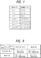
- Fig. 1 shows a coding table of the most common (1,7) code.
- (d,k,m,n) (1,7,2,3), i.e., the number of "0"s present between "1"s is a minimum of one and a maximum of seven, and the conversion bit ratio is 2 : 3.
- X represents an indeterminate bit which is determined by the pattern before this bit.
- Fig. 2 illustrates a sector format proposed as a standard of a rewritable 300-mm optical disk, as an example of a sector format using this (1,7) code.
- a 67-byte portion as a header field is an area in which address information is already recorded on a disk
- a 1,293-byte portion as a recording field is an area in which new information is recorded.
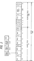
- Fig. 3 explains in detail a 3-byte DS portion and a 1,249-byte data field portion in that area.
- the data field shown in Fig. 3 contains a data sync pattern SB1-3 which indicates the start position of data, user data D1 to D1024, address data A1 and A2, CRC parities (error-detecting codes) C1 to C4, ECC parities (error-correcting codes) E1,1 to E10,14, and resync (resynchronization) patterns RS1 to RS59.
- SB1-3 data sync pattern
- CRC parities error-detecting codes
- ECC parities error-correcting codes
- E1,1 to E10,14 resync (resynchronization) patterns RS1 to RS59.
- the purpose of the resync pattern is to record a predetermined pattern at a fixed period. That is, if a large omission of data takes place in a reproduction signal during reproduction, this shifts the phase of a reproduction phase locked loop (PLL) clock, making byte synchronization of reproduction information impossible. Even if this synchronization difference propagates, it is possible to perform resynchronization by detecting the resync pattern and thereby minimize the damage.
- PLL phase locked loop
- the one-byte resync pattern proposed in this standard is a pattern "X01000001000" which is obtained by converting "C5" into the (1,7) code in hexadecimal notation.
- the resync pattern be a pattern which does not appear in user data. If the same pattern as the resync pattern appears in user data, a resync pattern detection circuit erroneously detects the resync pattern, producing a large error in reproduction data. To prevent this, windows for detecting the resync pattern can be provided in intervals before and after a point at which the resync pattern is expected to be detected, thereby making it impossible to detect the resync pattern in a data area.
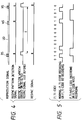
- Fig. 4 is a timing chart for explaining the function of such a resync detection window.
- RS represents a true resync signal
- UD represents user data
- WS represents a false resync signal in the user data
- T represents a fixed time.
- the window is narrowed so as not to erroneously detect the false resync pattern in the user data area.
- the resync pattern may fall outside the window due to an error in the frequency of the reproduction signal and therefore may no longer be detected.
- the window is widened so as not to miss the true resync pattern, the false resync pattern in the user data area may be erroneously detected.
- the standard of a rewritable optical disk using a (2,7) code makes use of a pattern, which satisfies a (2,7) limitation, i.e., "0010000000100100,” and does not appear in a data area written by the (2,7) code, as the resync pattern.
- the above-mentioned resync pattern of the (1,7) code is a pattern that appears in the user data area.
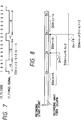
- Such a pattern in which an 8-t period is followed by a 7-t period meets the condition (d,k) (1,7) and does not appear in the (1,7)-code coding table mentioned earlier.
- the use of this pattern as the resync pattern can solve the above problem. If, however, this pattern is used, the resync pattern consists of at least two bytes. In Fig. 3, a resync pattern of one byte is added every 20 bytes of user data. The efficiency of recording capacity decreases if a resync pattern of two bytes must be added every 20 bytes of user data.
- Another problem on which the present invention has focused attention is a problem of DC free of a coded signal.
- a coded signal Assuming that symbol 1 is +1 point and symbol 0 is -1 point in a recording waveform column, the sum of points in a given waveform column is termed a digital sum value (DSV).
- DSV digital sum value
- a code in which a DSV in a certain predetermined interval is 0 or has a finite value does not have a DC component in its waveform column and hence is called a DC free code.
- a binary circuit of a reproducing apparatus can be simplified because no DC component is contained in a reproduction signal. This effectively reduces jitters produced by binary errors.
- DC free code examples include PE modulation, FM modulation, a Miller2 (Miller square) code, and an EFM code. These codes, however, have their respective drawbacks, such as a low recording density, a small window margin, and complexity in a coding circuit.
- RLL run length limited
- NRZI non return to zero inverted
- Fig. 6 is a block diagram showing one embodiment of a resync signal generation unit of a data recording apparatus according to the present invention.
- this resync signal generation unit includes a resync byte inserting circuit 1, a (1,7) encoder 2, an NRZI coding circuit 3, a delay circuit 4, a resync 10th bit control circuit 5, and a DSV determination circuit 6.
- a resync signal at a point A is "11001011”
- resync signals at points B and C are "X01000000101”
- a resync signal at a point D is "X01000000101" or "X01000000001.”
- Input recording data shown in Fig. 6 is data illustrated in a portion inside double lines in Fig. 3, i.e., data added with error-correcting codes and error-detecting codes.
- the resync byte inserting circuit 1 adds a portion from RS1 to RS59 shown in Fig. 3.
- hexadecimal data corresponding to a resync byte is "CB,” and this one-byte data "CB" is inserted every 20 bytes-of input data.
- the (1,7) encoder 2 performs (1,7) coding for recording data in accordance with the rule determined in Fig. 1.
- the resulting output resync signal has a pattern "X01000000101.”
- the output from the encoder 2 is converted into an NRZI signal by the NRZI coding circuit 3. That is, the output from the encoder is converted into a signal in which the polarity is inverted at a portion of "1" and remains unchanged at a portion of "0.”
- the DSV determination circuit 6 counts the DSV of the NRZI waveform column. As shown in Fig. 7, assuming that an interval corresponding to "1" of the NRZI signal is +1 point and an interval corresponding to "0" of the signal is -1 point, this count is obtained by calculating the sum total of these points.
- the 10th bit is used as a DC free control bit.
- the delay circuit 4 is necessary to cause a modulation signal to wait until the DSV determination circuit 6 outputs the determination result.
- the delay circuit 4 delays an input signal by a predetermined time by using a FIFO memory or the like and outputs the delayed signal.
- the resync 10th bit control circuit 5 is arranged, for example, as shown in Fig. 11. Referring to Fig. 11, this bit control circuit includes a resync 10th bit timing generating circuit 12, flip-flop circuits 13 and 14, and an exclusive-OR gate 15.
- the bit control circuit 5 performs control such that, when the output from the DSV determination circuit 6 is "1," the polarity is inverted at the timing of the 10th bit of a resync signal; when the output from the DSV determination circuit 6 is "0,” the polarity is not inverted.
- this resync signal can be recorded as a DC free signal since the maximum value of the sum total of DSVs of a waveform column to be recorded does not exceed the maximum value of DSV in one block.
- Fig. 10 illustrates an example of the arrangement of a resync pattern detection circuit in a reproducing apparatus.
- this detection circuit includes AND gates 7, 8, and 9, a NOR gate 10, and a 12-bit shift register 11.
- the resync pattern detection circuit performs pattern matching for an input reproduction signal to the shift register 11. Since the 10th bit of this shift register does not take part in this pattern matching, it is possible to detect a pattern of either "X01000000001" or "X01000000101.” In addition, in order to prevent detection of a false resync pattern in a user data area, a resync pattern detection window is opened only in the vicinity of a portion where a resync pattern is expected to be detected. Consequently, the AND gate 7 can extract only a true resync pattern.
- the resync pattern need only be one type, "X01000000001.”
- the resync signal generation unit is constituted as shown in Fig. 12.
- a resync 10th bit conversion circuit 16 for converting the 10th bit of a resync signal from "1" to "0" is provided in place of the delay circuit 4, the bit control circuit 5, and the DSV determination circuit 6 shown in Fig. 6. That is, this embodiment makes it unnecessary to use the means for inverting the polarity in a resync portion such as in the embodiment shown in Fig. 6. Instead, after (1,7) coding is performed by inserting a resync byte "CB"hex, it is required to replace "1," the 10th bit of the resync, with "0.”
- this resync pattern does not appear in the (1,7) code, it advantageously decreases the possibility of erroneous detection of the resync pattern in a data area.
- the pattern (b) has performance as a resync pattern equivalent to that of the pattern (a). That is, when the width of a detection window is set at ⁇ 6 channel bits in the resync detection circuit, as shown in Fig. 10, no resync pattern erroneous detection occurs even if one channel bit error takes place.
- the width of a detection window must be set at ⁇ 5 channel bits in order that no resync pattern erroneous detection takes place even if one channel bit error occurs.
- the width of a detection window must be set at ⁇ 4 channel bits under the same conditions.
- a resync pattern of one byte can be set in the (1,7) code, and this improves the efficiency of recording density compared to a two-byte resync pattern.
- recording can be performed in a DC free waveform column, a reproducing apparatus can be designed easily, and jitters upon binarization are also reduced.
- the data recording method and the data recording apparatus of the present invention can perform recording and reproduction with a higher reliability.
Landscapes
- Engineering & Computer Science (AREA)
- Signal Processing (AREA)
- Signal Processing For Digital Recording And Reproducing (AREA)
Applications Claiming Priority (2)
| Application Number | Priority Date | Filing Date | Title |
|---|---|---|---|
| JP347824/92 | 1992-12-28 | ||
| JP04347824A JP3083011B2 (ja) | 1992-12-28 | 1992-12-28 | データ記録方法及び装置 |
Publications (3)
| Publication Number | Publication Date |
|---|---|
| EP0605206A2 true EP0605206A2 (fr) | 1994-07-06 |
| EP0605206A3 EP0605206A3 (fr) | 1995-01-11 |
| EP0605206B1 EP0605206B1 (fr) | 1999-06-02 |
Family
ID=18392850
Family Applications (1)
| Application Number | Title | Priority Date | Filing Date |
|---|---|---|---|
| EP93310474A Expired - Lifetime EP0605206B1 (fr) | 1992-12-28 | 1993-12-23 | Méthode d'enregistrement de données et appareil d'enregistrement de données |
Country Status (4)
| Country | Link |
|---|---|
| US (1) | US5451943A (fr) |
| EP (1) | EP0605206B1 (fr) |
| JP (1) | JP3083011B2 (fr) |
| DE (1) | DE69325151T2 (fr) |
Cited By (4)
| Publication number | Priority date | Publication date | Assignee | Title |
|---|---|---|---|---|
| EP0751518A2 (fr) * | 1995-06-30 | 1997-01-02 | Fujitsu Limited | Circuit de détermination du bit d'ajustement |
| EP0817191A2 (fr) * | 1996-06-21 | 1998-01-07 | Pioneer Electronic Corporation | Appareil d'enregistrement d'informations, support d'enregistrement d'informations et appareil de reproduction d'informations |
| EP1083687A1 (fr) * | 1998-08-24 | 2001-03-14 | Sony Corporation | Dispositif et procede de modulation, dispositif et procede de demodulation et support associe |
| CN100392740C (zh) * | 2002-09-24 | 2008-06-04 | 联发科技股份有限公司 | 一种对编码系统做数字总和值保护的方法及装置 |
Families Citing this family (27)
| Publication number | Priority date | Publication date | Assignee | Title |
|---|---|---|---|---|
| JP2863052B2 (ja) * | 1993-03-15 | 1999-03-03 | 松下電器産業株式会社 | デジタルデータ符号化方法、復号化方法、符号化装置および復号化装置 |
| USRE41022E1 (en) | 1993-03-15 | 2009-12-01 | Panasonic Corporation | Optical recording disk capable of resynchronization in digital encoding and decoding |
| JP3227901B2 (ja) * | 1993-05-21 | 2001-11-12 | ソニー株式会社 | 変調方法及び復調装置 |
| US5699062A (en) * | 1995-02-01 | 1997-12-16 | International Business Machines Corporation | Transmission code having local parity |
| JP3243140B2 (ja) * | 1995-02-20 | 2002-01-07 | パイオニア株式会社 | データ変換方式 |
| JP3464558B2 (ja) * | 1995-03-31 | 2003-11-10 | 富士通株式会社 | エンコード装置及び記憶装置 |
| US5608397A (en) * | 1995-08-15 | 1997-03-04 | Lucent Technologies Inc. | Method and apparatus for generating DC-free sequences |
| US5960041A (en) * | 1995-09-21 | 1999-09-28 | Lucent Technologies Inc. | Method and apparatus for generating high rate codes for recording information on a magnetic medium |
| US5699434A (en) | 1995-12-12 | 1997-12-16 | Hewlett-Packard Company | Method of inhibiting copying of digital data |
| JPH09265736A (ja) * | 1996-03-25 | 1997-10-07 | Toshiba Corp | 情報処理装置 |
| USRE39771E1 (en) * | 1996-07-31 | 2007-08-14 | Matsushita Electric Industrial Co., Ltd. | Code conversion method and apparatus, code recording medium, code recording apparatus and code reproducing apparatus |
| US5898394A (en) * | 1996-07-31 | 1999-04-27 | Matsushita Electric Industrial Co., Ltd. | Code conversion method and apparatus, code recording medium, code recording apparatus and code reproducing apparatus |
| US6061193A (en) * | 1997-01-21 | 2000-05-09 | Seagate Technology, Inc. | Method and apparatus for detection in digital magnetic recording |
| US6052072A (en) * | 1997-04-01 | 2000-04-18 | Seagate Technology, Inc. | System and scheme for maximum transition run length codes with location dependent constraints |
| US6011497A (en) * | 1997-04-01 | 2000-01-04 | Seagate Technology, Inc. | Location dependent maximum transition run length code with alternating code word length and efficient K constraint |
| US6212661B1 (en) | 1997-08-11 | 2001-04-03 | Seagate Technology, Inc. | Static viterbi detector for channels utilizing a code having time varying constraints |
| US6493162B1 (en) | 1997-12-05 | 2002-12-10 | Seagate Technology Llc | Frame synchronization for viterbi detector |
| JP3717024B2 (ja) * | 1997-12-12 | 2005-11-16 | ソニー株式会社 | 復調装置および方法 |
| US5969649A (en) * | 1998-02-17 | 1999-10-19 | International Business Machines Corporation | Run length limited encoding/decoding with robust resync |
| US6317856B1 (en) | 1998-03-19 | 2001-11-13 | Seagate Technology Llc | Encoder and a method of encoding for partial response channels |
| JP3204217B2 (ja) | 1998-06-17 | 2001-09-04 | 日本電気株式会社 | 記録符号変換方法及び復号方法並びに同期信号挿入方法 |
| JP2000105981A (ja) * | 1998-09-29 | 2000-04-11 | Toshiba Corp | データ変換方法および装置 |
| KR100424482B1 (ko) * | 2000-06-22 | 2004-03-24 | 엘지전자 주식회사 | 일련의 데이터 워드를 변조신호로 변환하는 방법 및 장치 |
| KR100716956B1 (ko) * | 2000-10-11 | 2007-05-10 | 삼성전자주식회사 | 데이터 변조 방법 및 그 검출 방법 |
| JP4178795B2 (ja) * | 2002-01-23 | 2008-11-12 | ソニー株式会社 | 変調装置および方法、dsv制御ビット生成方法、記録媒体、並びにプログラム |
| TW594700B (en) * | 2002-06-07 | 2004-06-21 | Mediatek Inc | Method for performing DSV protection on EFM/EFM+ encoding system and its device |
| JP2004213767A (ja) * | 2002-12-27 | 2004-07-29 | Toshiba Corp | データ変換装置及びデータ変換方法 |
Citations (5)
| Publication number | Priority date | Publication date | Assignee | Title |
|---|---|---|---|---|
| WO1985001402A1 (fr) * | 1983-09-19 | 1985-03-28 | Storage Technology Partners Ii | Systeme de codage de configuration de synchronisation pour des secteurs de donnees enregistres sur un support de stockage |
| JPS62272726A (ja) * | 1986-05-21 | 1987-11-26 | Oki Electric Ind Co Ltd | 符号化回路 |
| JPS63160422A (ja) * | 1986-12-24 | 1988-07-04 | Sony Corp | 2値信号の符号化方法 |
| JPH02227880A (ja) * | 1989-03-01 | 1990-09-11 | Hitachi Denshi Ltd | データ記録再生装置 |
| EP0420179A2 (fr) * | 1989-09-26 | 1991-04-03 | Hitachi, Ltd. | Méthode et dispositif pour l'enregistrement et la reproduction des données |
Family Cites Families (8)
| Publication number | Priority date | Publication date | Assignee | Title |
|---|---|---|---|---|
| US4451819A (en) * | 1981-06-22 | 1984-05-29 | Memorex Corporation | Method and apparatus for decoding binary data |
| US4567464A (en) * | 1983-01-28 | 1986-01-28 | International Business Machines Corporation | Fixed rate constrained channel code generating and recovery method and means having spectral nulls for pilot signal insertion |
| US4697167A (en) * | 1983-09-19 | 1987-09-29 | Storage Technology Corporation | Sync pattern encoding system for data sectors written on a storage medium |
| US4571575A (en) * | 1984-05-03 | 1986-02-18 | Sunol Systems Incorporated | Synchronization-promoting data coding method |
| JPH0656958B2 (ja) * | 1986-07-03 | 1994-07-27 | キヤノン株式会社 | 情報デ−タ復元装置 |
| US4975916A (en) * | 1988-07-26 | 1990-12-04 | International Business Machines Corporation | Character snychronization |
| US5231545A (en) * | 1991-06-04 | 1993-07-27 | Quantum Corporation | Fault tolerant rll data sector address mark decoder |
| JP3224418B2 (ja) * | 1992-05-21 | 2001-10-29 | パイオニア株式会社 | 記録データ列2次変調方法 |
-
1992
- 1992-12-28 JP JP04347824A patent/JP3083011B2/ja not_active Expired - Fee Related
-
1993
- 1993-12-23 EP EP93310474A patent/EP0605206B1/fr not_active Expired - Lifetime
- 1993-12-23 DE DE69325151T patent/DE69325151T2/de not_active Expired - Fee Related
- 1993-12-23 US US08/172,102 patent/US5451943A/en not_active Expired - Fee Related
Patent Citations (5)
| Publication number | Priority date | Publication date | Assignee | Title |
|---|---|---|---|---|
| WO1985001402A1 (fr) * | 1983-09-19 | 1985-03-28 | Storage Technology Partners Ii | Systeme de codage de configuration de synchronisation pour des secteurs de donnees enregistres sur un support de stockage |
| JPS62272726A (ja) * | 1986-05-21 | 1987-11-26 | Oki Electric Ind Co Ltd | 符号化回路 |
| JPS63160422A (ja) * | 1986-12-24 | 1988-07-04 | Sony Corp | 2値信号の符号化方法 |
| JPH02227880A (ja) * | 1989-03-01 | 1990-09-11 | Hitachi Denshi Ltd | データ記録再生装置 |
| EP0420179A2 (fr) * | 1989-09-26 | 1991-04-03 | Hitachi, Ltd. | Méthode et dispositif pour l'enregistrement et la reproduction des données |
Non-Patent Citations (5)
| Title |
|---|
| IBM TDB, vol.29, no.1, 1986, ARMONK ,NY ,USA pages 151 - 157 'FAULT-TOLERANT SYNC BYTE FOR RUN-LENGTH-LIMITED CODES' * |
| PATENT ABSTRACTS OF JAPAN vol. 12, no. 162 (E-609) 17 May 1988 & JP-A-62 272 726 (OKI ELECTRIC IND CO LTD) 26 November 1987 * |
| PATENT ABSTRACTS OF JAPAN vol. 12, no. 423 (E-680) 9 November 1988 & JP-A-63 160 422 (SONY CORP.) 4 July 1988 * |
| PATENT ABSTRACTS OF JAPAN vol. 14, no. 538 (P-1136) 28 November 1990 & JP-A-02 227 880 (HITACHI DENSHI LTD) 11 September 1990 * |
| TOPICAL MEETING ON OPTICAL DATA STORAGE, 13 March 1987, STATELINE NEVADA pages 115 - 117 CHARLES SHINN II 'CHARGE CONSTRAINED (1,7) CODE FOR MAGNETO OPTIC RECORDING' * |
Cited By (23)
| Publication number | Priority date | Publication date | Assignee | Title |
|---|---|---|---|---|
| USRE38719E1 (en) | 1995-06-30 | 2005-04-05 | Fujitsu Limited | Adjust bit determining circuit |
| EP0751518A2 (fr) * | 1995-06-30 | 1997-01-02 | Fujitsu Limited | Circuit de détermination du bit d'ajustement |
| EP0751518A3 (fr) * | 1995-06-30 | 1999-06-09 | Fujitsu Limited | Circuit de détermination du bit d'ajustement |
| EP1168332A2 (fr) * | 1995-06-30 | 2002-01-02 | Fujitsu Limited | Circuit de détermination du bit d'ajustement |
| EP1168332A3 (fr) * | 1995-06-30 | 2002-04-10 | Fujitsu Limited | Circuit de détermination du bit d'ajustement |
| EP0817191A3 (fr) * | 1996-06-21 | 1999-01-20 | Pioneer Electronic Corporation | Appareil d'enregistrement d'informations, support d'enregistrement d'informations et appareil de reproduction d'informations |
| EP0817191A2 (fr) * | 1996-06-21 | 1998-01-07 | Pioneer Electronic Corporation | Appareil d'enregistrement d'informations, support d'enregistrement d'informations et appareil de reproduction d'informations |
| EP1288944A2 (fr) * | 1996-06-21 | 2003-03-05 | Pioneer Electronic Corporation | Appareil d'enregistrement d'informations, support d'enregistrement d'informations et appareil de reproduction d'informations |
| EP1288944A3 (fr) * | 1996-06-21 | 2003-03-26 | Pioneer Electronic Corporation | Appareil d'enregistrement d'informations, support d'enregistrement d'informations et appareil de reproduction d'informations |
| US7526032B2 (en) | 1998-08-24 | 2009-04-28 | Sony Corporation | Sync signal insertion that breaks a maximum bit-run and has a particular detection distance between two or more sync patterns |
| US7054373B2 (en) | 1998-08-24 | 2006-05-30 | Sony Corporation | Method and apparatus for modulating and demodulating data into a variable-length code and providing a sync signal to the train of codes |
| EP1083687A1 (fr) * | 1998-08-24 | 2001-03-14 | Sony Corporation | Dispositif et procede de modulation, dispositif et procede de demodulation et support associe |
| EP1083687A4 (fr) * | 1998-08-24 | 2003-07-30 | Sony Corp | Dispositif et procede de modulation, dispositif et procede de demodulation et support associe |
| US7046736B2 (en) | 1998-08-24 | 2006-05-16 | Sony Corporation | Method and apparatus for modulating and demodulating data into a variable-length code and providing a sync signal to the train of codes |
| US7046735B2 (en) | 1998-08-24 | 2006-05-16 | Sony Corporation | Method and apparatus for modulating and demodulating data into a variable-length code and providing a sync signal to the train of codes |
| US7050506B2 (en) | 1998-08-24 | 2006-05-23 | Sony Corporation | Method and apparatus for modulating and demodulating data into a variable-length code and providing a sync signal to the train of codes |
| US6983022B2 (en) | 1998-08-24 | 2006-01-03 | Sony Corporation | Method and apparatus for modulating and demodulating data into a variable-length code and providing a sync signal to the train of codes |
| US7190726B2 (en) | 1998-08-24 | 2007-03-13 | Sony Corporation | Method and apparatus for modulating and demodulating data into a variable-length code and providing a sync signal to the train of codes |
| US7200175B2 (en) | 1998-08-24 | 2007-04-03 | Sony Corporation | Data-modulating apparatus, data-modulating method, data-demodulating apparatus, data-demodulating method, and data-providing medium |
| US7266153B2 (en) | 1998-08-24 | 2007-09-04 | Sony Corporation | Method and apparatus for modulating and demodulating data into a variable length code and a providing medium for implementing the method |
| US7283592B2 (en) | 1998-08-24 | 2007-10-16 | Sony Corporation | Method and apparatus for modulating and demodulating data into a variable length code and a providing medium for implementing the method |
| US6879637B1 (en) | 1998-08-24 | 2005-04-12 | Sony Corporation | Method and apparatus for modulating and demodulating data into a variable length code and a providing medium for implementing the method |
| CN100392740C (zh) * | 2002-09-24 | 2008-06-04 | 联发科技股份有限公司 | 一种对编码系统做数字总和值保护的方法及装置 |
Also Published As
| Publication number | Publication date |
|---|---|
| US5451943A (en) | 1995-09-19 |
| EP0605206B1 (fr) | 1999-06-02 |
| JPH06195893A (ja) | 1994-07-15 |
| DE69325151D1 (de) | 1999-07-08 |
| DE69325151T2 (de) | 1999-10-28 |
| EP0605206A3 (fr) | 1995-01-11 |
| JP3083011B2 (ja) | 2000-09-04 |
Similar Documents
| Publication | Publication Date | Title |
|---|---|---|
| EP0605206B1 (fr) | Méthode d'enregistrement de données et appareil d'enregistrement de données | |
| EP0673028B1 (fr) | Support d'enregistrement, appareil d'enregistrement de signal associé, et appareil de reproduction de signal associé | |
| EP1083687B1 (fr) | Procede et dispositif de modulation et demodulation de donnees a l'aide d'un code a longueur variable | |
| US4596981A (en) | Synchronizing signal detecting circuit in a digital signal transmitting system | |
| US6097320A (en) | Encoder/decoder system with suppressed error propagation | |
| JP3394127B2 (ja) | ディジタルデータの伝送方法 | |
| US5537422A (en) | Synchronization signal detector, synchronization signal detecting method and demodulator | |
| JP3141011B2 (ja) | 堅固な再同期を使用するランレングス限定コード化/デコード | |
| JP3722331B2 (ja) | 変調装置および方法、並びに記録媒体 | |
| KR100310217B1 (ko) | 디지탈데이타처리장치및그방법 | |
| US6950042B2 (en) | Modulating apparatus and method, and DSV control bit producing method | |
| US7256718B2 (en) | Modulation apparatus and method | |
| JPH07118657B2 (ja) | 2進デ−タ符号化及び復号化方式 | |
| US4860324A (en) | Information data recovering apparatus | |
| EP0318227B1 (fr) | Méthode et système de synchronisation de trame | |
| US5625505A (en) | Method of and apparatus for regenerating partial-response record signal | |
| US6172622B1 (en) | Demodulating device, demodulating method and supply medium | |
| EP0853805B1 (fr) | Transmission, enregistrement et reproduction d'un signal d'information numerique | |
| US20020135500A1 (en) | Digital data modulating method and apparatus and modulated data recording medium using the same | |
| JP2000068850A (ja) | 復調装置および方法、並びに提供媒体 | |
| JPH05235920A (ja) | 同期化方法及びこの方法を実施する回路配置 | |
| JP3697809B2 (ja) | 信号検出回路 | |
| JPH0991885A (ja) | 同期情報付加方法及び同期情報付加装置、並びに同期情報検出方法及び同期情報検出装置 | |
| KR940000681B1 (ko) | 디지탈 신호의 에러 정정회로 | |
| JP2870060B2 (ja) | 符号化方法 |
Legal Events
| Date | Code | Title | Description |
|---|---|---|---|
| PUAI | Public reference made under article 153(3) epc to a published international application that has entered the european phase |
Free format text: ORIGINAL CODE: 0009012 |
|
| AK | Designated contracting states |
Kind code of ref document: A2 Designated state(s): DE FR GB IT NL |
|
| PUAL | Search report despatched |
Free format text: ORIGINAL CODE: 0009013 |
|
| AK | Designated contracting states |
Kind code of ref document: A3 Designated state(s): DE FR GB IT NL |
|
| 17P | Request for examination filed |
Effective date: 19950526 |
|
| 17Q | First examination report despatched |
Effective date: 19970321 |
|
| GRAG | Despatch of communication of intention to grant |
Free format text: ORIGINAL CODE: EPIDOS AGRA |
|
| GRAG | Despatch of communication of intention to grant |
Free format text: ORIGINAL CODE: EPIDOS AGRA |
|
| GRAH | Despatch of communication of intention to grant a patent |
Free format text: ORIGINAL CODE: EPIDOS IGRA |
|
| GRAH | Despatch of communication of intention to grant a patent |
Free format text: ORIGINAL CODE: EPIDOS IGRA |
|
| GRAA | (expected) grant |
Free format text: ORIGINAL CODE: 0009210 |
|
| AK | Designated contracting states |
Kind code of ref document: B1 Designated state(s): DE FR GB IT NL |
|
| PG25 | Lapsed in a contracting state [announced via postgrant information from national office to epo] |
Ref country code: NL Free format text: LAPSE BECAUSE OF FAILURE TO SUBMIT A TRANSLATION OF THE DESCRIPTION OR TO PAY THE FEE WITHIN THE PRESCRIBED TIME-LIMIT Effective date: 19990602 Ref country code: IT Free format text: LAPSE BECAUSE OF FAILURE TO SUBMIT A TRANSLATION OF THE DESCRIPTION OR TO PAY THE FEE WITHIN THE PRESCRIBED TIME-LIMIT;WARNING: LAPSES OF ITALIAN PATENTS WITH EFFECTIVE DATE BEFORE 2007 MAY HAVE OCCURRED AT ANY TIME BEFORE 2007. THE CORRECT EFFECTIVE DATE MAY BE DIFFERENT FROM THE ONE RECORDED. Effective date: 19990602 |
|
| REF | Corresponds to: |
Ref document number: 69325151 Country of ref document: DE Date of ref document: 19990708 |
|
| ET | Fr: translation filed | ||
| PLBE | No opposition filed within time limit |
Free format text: ORIGINAL CODE: 0009261 |
|
| STAA | Information on the status of an ep patent application or granted ep patent |
Free format text: STATUS: NO OPPOSITION FILED WITHIN TIME LIMIT |
|
| 26N | No opposition filed | ||
| REG | Reference to a national code |
Ref country code: GB Ref legal event code: IF02 |
|
| PGFP | Annual fee paid to national office [announced via postgrant information from national office to epo] |
Ref country code: GB Payment date: 20051209 Year of fee payment: 13 |
|
| PGFP | Annual fee paid to national office [announced via postgrant information from national office to epo] |
Ref country code: FR Payment date: 20051216 Year of fee payment: 13 |
|
| PGFP | Annual fee paid to national office [announced via postgrant information from national office to epo] |
Ref country code: DE Payment date: 20060224 Year of fee payment: 13 |
|
| PG25 | Lapsed in a contracting state [announced via postgrant information from national office to epo] |
Ref country code: DE Free format text: LAPSE BECAUSE OF NON-PAYMENT OF DUE FEES Effective date: 20070703 |
|
| GBPC | Gb: european patent ceased through non-payment of renewal fee |
Effective date: 20061223 |
|
| REG | Reference to a national code |
Ref country code: FR Ref legal event code: ST Effective date: 20070831 |
|
| PG25 | Lapsed in a contracting state [announced via postgrant information from national office to epo] |
Ref country code: GB Free format text: LAPSE BECAUSE OF NON-PAYMENT OF DUE FEES Effective date: 20061223 |
|
| PG25 | Lapsed in a contracting state [announced via postgrant information from national office to epo] |
Ref country code: FR Free format text: LAPSE BECAUSE OF NON-PAYMENT OF DUE FEES Effective date: 20070102 |