EP0572896B1 - Magnetischer Entwickler und Verfahren zur Erkennung von Zeichen aus magnetischer Tinte - Google Patents
Magnetischer Entwickler und Verfahren zur Erkennung von Zeichen aus magnetischer Tinte Download PDFInfo
- Publication number
- EP0572896B1 EP0572896B1 EP93108365A EP93108365A EP0572896B1 EP 0572896 B1 EP0572896 B1 EP 0572896B1 EP 93108365 A EP93108365 A EP 93108365A EP 93108365 A EP93108365 A EP 93108365A EP 0572896 B1 EP0572896 B1 EP 0572896B1
- Authority
- EP
- European Patent Office
- Prior art keywords
- magnetic
- developer according
- magnetic developer
- temperature
- range
- Prior art date
- Legal status (The legal status is an assumption and is not a legal conclusion. Google has not performed a legal analysis and makes no representation as to the accuracy of the status listed.)
- Expired - Lifetime
Links
- 230000005291 magnetic effect Effects 0.000 title claims description 273
- 238000000034 method Methods 0.000 title claims description 49
- 229930195733 hydrocarbon Natural products 0.000 claims description 88
- 150000002430 hydrocarbons Chemical class 0.000 claims description 88
- 239000004215 Carbon black (E152) Substances 0.000 claims description 78
- 239000000696 magnetic material Substances 0.000 claims description 58
- VYPSYNLAJGMNEJ-UHFFFAOYSA-N Silicium dioxide Chemical compound O=[Si]=O VYPSYNLAJGMNEJ-UHFFFAOYSA-N 0.000 claims description 51
- 238000001938 differential scanning calorimetry curve Methods 0.000 claims description 36
- 229920005989 resin Polymers 0.000 claims description 33
- 239000011347 resin Substances 0.000 claims description 33
- 239000011230 binding agent Substances 0.000 claims description 31
- 239000000843 powder Substances 0.000 claims description 25
- 239000000377 silicon dioxide Substances 0.000 claims description 25
- 230000005389 magnetism Effects 0.000 claims description 22
- 239000002245 particle Substances 0.000 claims description 20
- 230000005415 magnetization Effects 0.000 claims description 17
- 238000007639 printing Methods 0.000 claims description 13
- 239000003054 catalyst Substances 0.000 claims description 11
- 125000002947 alkylene group Chemical group 0.000 claims description 8
- 229910052799 carbon Inorganic materials 0.000 claims description 8
- UGFAIRIUMAVXCW-UHFFFAOYSA-N Carbon monoxide Chemical compound [O+]#[C-] UGFAIRIUMAVXCW-UHFFFAOYSA-N 0.000 claims description 7
- UFHFLCQGNIYNRP-UHFFFAOYSA-N Hydrogen Chemical compound [H][H] UFHFLCQGNIYNRP-UHFFFAOYSA-N 0.000 claims description 7
- 229910002091 carbon monoxide Inorganic materials 0.000 claims description 7
- 239000001257 hydrogen Substances 0.000 claims description 7
- 229910052739 hydrogen Inorganic materials 0.000 claims description 7
- 230000035515 penetration Effects 0.000 claims description 7
- 241000370685 Arge Species 0.000 claims description 6
- 238000005194 fractionation Methods 0.000 claims description 6
- 238000000605 extraction Methods 0.000 claims description 5
- 238000006116 polymerization reaction Methods 0.000 claims description 5
- 229920006395 saturated elastomer Polymers 0.000 claims description 4
- 229910044991 metal oxide Inorganic materials 0.000 claims description 3
- 150000004706 metal oxides Chemical class 0.000 claims description 3
- ABDKAPXRBAPSQN-UHFFFAOYSA-N veratrole Chemical compound COC1=CC=CC=C1OC ABDKAPXRBAPSQN-UHFFFAOYSA-N 0.000 claims description 3
- 239000001993 wax Substances 0.000 description 87
- 230000000052 comparative effect Effects 0.000 description 23
- 238000011109 contamination Methods 0.000 description 21
- 238000005259 measurement Methods 0.000 description 13
- 239000003795 chemical substances by application Substances 0.000 description 12
- 230000007423 decrease Effects 0.000 description 12
- 230000000694 effects Effects 0.000 description 12
- 230000008569 process Effects 0.000 description 12
- 238000002844 melting Methods 0.000 description 11
- 230000008018 melting Effects 0.000 description 11
- KWYUFKZDYYNOTN-UHFFFAOYSA-M Potassium hydroxide Chemical compound [OH-].[K+] KWYUFKZDYYNOTN-UHFFFAOYSA-M 0.000 description 9
- 238000009826 distribution Methods 0.000 description 9
- 238000012546 transfer Methods 0.000 description 9
- 238000004140 cleaning Methods 0.000 description 6
- 239000007789 gas Substances 0.000 description 6
- 239000000155 melt Substances 0.000 description 6
- XEEYBQQBJWHFJM-UHFFFAOYSA-N Iron Chemical compound [Fe] XEEYBQQBJWHFJM-UHFFFAOYSA-N 0.000 description 5
- 239000002253 acid Substances 0.000 description 5
- 238000011161 development Methods 0.000 description 5
- 239000000975 dye Substances 0.000 description 5
- 229910052751 metal Inorganic materials 0.000 description 5
- 239000002184 metal Substances 0.000 description 5
- 230000003647 oxidation Effects 0.000 description 5
- 238000007254 oxidation reaction Methods 0.000 description 5
- PPBRXRYQALVLMV-UHFFFAOYSA-N Styrene Chemical compound C=CC1=CC=CC=C1 PPBRXRYQALVLMV-UHFFFAOYSA-N 0.000 description 4
- 230000015572 biosynthetic process Effects 0.000 description 4
- 230000008859 change Effects 0.000 description 4
- 238000001816 cooling Methods 0.000 description 4
- 238000001640 fractional crystallisation Methods 0.000 description 4
- 230000000704 physical effect Effects 0.000 description 4
- -1 polyethylene Polymers 0.000 description 4
- 238000002360 preparation method Methods 0.000 description 4
- 239000000047 product Substances 0.000 description 4
- 230000009467 reduction Effects 0.000 description 4
- 238000007711 solidification Methods 0.000 description 4
- 230000008023 solidification Effects 0.000 description 4
- 238000003786 synthesis reaction Methods 0.000 description 4
- 230000007704 transition Effects 0.000 description 4
- IJGRMHOSHXDMSA-UHFFFAOYSA-N Atomic nitrogen Chemical compound N#N IJGRMHOSHXDMSA-UHFFFAOYSA-N 0.000 description 3
- BTBUEUYNUDRHOZ-UHFFFAOYSA-N Borate Chemical compound [O-]B([O-])[O-] BTBUEUYNUDRHOZ-UHFFFAOYSA-N 0.000 description 3
- 230000009471 action Effects 0.000 description 3
- 239000000654 additive Substances 0.000 description 3
- 238000005273 aeration Methods 0.000 description 3
- 238000002425 crystallisation Methods 0.000 description 3
- 230000008025 crystallization Effects 0.000 description 3
- 235000003891 ferrous sulphate Nutrition 0.000 description 3
- 239000011790 ferrous sulphate Substances 0.000 description 3
- 238000005227 gel permeation chromatography Methods 0.000 description 3
- BAUYGSIQEAFULO-UHFFFAOYSA-L iron(2+) sulfate (anhydrous) Chemical compound [Fe+2].[O-]S([O-])(=O)=O BAUYGSIQEAFULO-UHFFFAOYSA-L 0.000 description 3
- 229910000359 iron(II) sulfate Inorganic materials 0.000 description 3
- 238000002156 mixing Methods 0.000 description 3
- 239000000203 mixture Substances 0.000 description 3
- 229910052757 nitrogen Inorganic materials 0.000 description 3
- 230000035699 permeability Effects 0.000 description 3
- 239000000049 pigment Substances 0.000 description 3
- 229920000642 polymer Polymers 0.000 description 3
- 150000003839 salts Chemical class 0.000 description 3
- 239000007858 starting material Substances 0.000 description 3
- RFFLAFLAYFXFSW-UHFFFAOYSA-N 1,2-dichlorobenzene Chemical compound ClC1=CC=CC=C1Cl RFFLAFLAYFXFSW-UHFFFAOYSA-N 0.000 description 2
- VGGSQFUCUMXWEO-UHFFFAOYSA-N Ethene Chemical compound C=C VGGSQFUCUMXWEO-UHFFFAOYSA-N 0.000 description 2
- 239000005977 Ethylene Substances 0.000 description 2
- 239000004698 Polyethylene Substances 0.000 description 2
- 238000010521 absorption reaction Methods 0.000 description 2
- 239000003086 colorant Substances 0.000 description 2
- 238000010438 heat treatment Methods 0.000 description 2
- 230000006872 improvement Effects 0.000 description 2
- 229910052742 iron Inorganic materials 0.000 description 2
- 239000006247 magnetic powder Substances 0.000 description 2
- 239000000463 material Substances 0.000 description 2
- NYGZLYXAPMMJTE-UHFFFAOYSA-M metanil yellow Chemical group [Na+].[O-]S(=O)(=O)C1=CC=CC(N=NC=2C=CC(NC=3C=CC=CC=3)=CC=2)=C1 NYGZLYXAPMMJTE-UHFFFAOYSA-M 0.000 description 2
- 239000000178 monomer Substances 0.000 description 2
- 238000007645 offset printing Methods 0.000 description 2
- 230000003287 optical effect Effects 0.000 description 2
- 230000002093 peripheral effect Effects 0.000 description 2
- 229920000573 polyethylene Polymers 0.000 description 2
- 150000003242 quaternary ammonium salts Chemical class 0.000 description 2
- 230000000717 retained effect Effects 0.000 description 2
- YGSDEFSMJLZEOE-UHFFFAOYSA-N salicylic acid Chemical compound OC(=O)C1=CC=CC=C1O YGSDEFSMJLZEOE-UHFFFAOYSA-N 0.000 description 2
- 239000002689 soil Substances 0.000 description 2
- 239000002904 solvent Substances 0.000 description 2
- 239000000758 substrate Substances 0.000 description 2
- 125000000391 vinyl group Chemical group [H]C([*])=C([H])[H] 0.000 description 2
- 229920002554 vinyl polymer Polymers 0.000 description 2
- LNETULKMXZVUST-UHFFFAOYSA-N 1-naphthoic acid Chemical compound C1=CC=C2C(C(=O)O)=CC=CC2=C1 LNETULKMXZVUST-UHFFFAOYSA-N 0.000 description 1
- 229920002126 Acrylic acid copolymer Polymers 0.000 description 1
- 238000004438 BET method Methods 0.000 description 1
- VYZAMTAEIAYCRO-UHFFFAOYSA-N Chromium Chemical compound [Cr] VYZAMTAEIAYCRO-UHFFFAOYSA-N 0.000 description 1
- BPQQTUXANYXVAA-UHFFFAOYSA-N Orthosilicate Chemical compound [O-][Si]([O-])([O-])[O-] BPQQTUXANYXVAA-UHFFFAOYSA-N 0.000 description 1
- 239000004793 Polystyrene Substances 0.000 description 1
- 239000004111 Potassium silicate Substances 0.000 description 1
- 239000006087 Silane Coupling Agent Substances 0.000 description 1
- 239000004115 Sodium Silicate Substances 0.000 description 1
- 239000004110 Zinc silicate Substances 0.000 description 1
- YKTSYUJCYHOUJP-UHFFFAOYSA-N [O--].[Al+3].[Al+3].[O-][Si]([O-])([O-])[O-] Chemical compound [O--].[Al+3].[Al+3].[O-][Si]([O-])([O-])[O-] YKTSYUJCYHOUJP-UHFFFAOYSA-N 0.000 description 1
- 150000001252 acrylic acid derivatives Chemical class 0.000 description 1
- 125000000217 alkyl group Chemical group 0.000 description 1
- 239000007864 aqueous solution Substances 0.000 description 1
- QSRFYFHZPSGRQX-UHFFFAOYSA-N benzyl(tributyl)azanium Chemical compound CCCC[N+](CCCC)(CCCC)CC1=CC=CC=C1 QSRFYFHZPSGRQX-UHFFFAOYSA-N 0.000 description 1
- 230000000903 blocking effect Effects 0.000 description 1
- 150000001642 boronic acid derivatives Chemical class 0.000 description 1
- 238000011088 calibration curve Methods 0.000 description 1
- 239000003990 capacitor Substances 0.000 description 1
- 239000002775 capsule Substances 0.000 description 1
- 125000004432 carbon atom Chemical group C* 0.000 description 1
- 239000006229 carbon black Substances 0.000 description 1
- 229910000420 cerium oxide Inorganic materials 0.000 description 1
- 238000006243 chemical reaction Methods 0.000 description 1
- 239000007795 chemical reaction product Substances 0.000 description 1
- 229910052804 chromium Inorganic materials 0.000 description 1
- 239000011651 chromium Substances 0.000 description 1
- 239000011248 coating agent Substances 0.000 description 1
- 238000000576 coating method Methods 0.000 description 1
- 239000008119 colloidal silica Substances 0.000 description 1
- 238000013329 compounding Methods 0.000 description 1
- 239000000470 constituent Substances 0.000 description 1
- 229920001577 copolymer Polymers 0.000 description 1
- 239000013078 crystal Substances 0.000 description 1
- 230000006866 deterioration Effects 0.000 description 1
- JGFBRKRYDCGYKD-UHFFFAOYSA-N dibutyl(oxo)tin Chemical compound CCCC[Sn](=O)CCCC JGFBRKRYDCGYKD-UHFFFAOYSA-N 0.000 description 1
- WCRDXYSYPCEIAK-UHFFFAOYSA-N dibutylstannane Chemical compound CCCC[SnH2]CCCC WCRDXYSYPCEIAK-UHFFFAOYSA-N 0.000 description 1
- QULMZVWEGVTWJY-UHFFFAOYSA-N dicyclohexyl(oxo)tin Chemical compound C1CCCCC1[Sn](=O)C1CCCCC1 QULMZVWEGVTWJY-UHFFFAOYSA-N 0.000 description 1
- BRCGUTSVMPKEKH-UHFFFAOYSA-N dicyclohexyltin Chemical compound C1CCCCC1[Sn]C1CCCCC1 BRCGUTSVMPKEKH-UHFFFAOYSA-N 0.000 description 1
- 235000014113 dietary fatty acids Nutrition 0.000 description 1
- LQRUPWUPINJLMU-UHFFFAOYSA-N dioctyl(oxo)tin Chemical compound CCCCCCCC[Sn](=O)CCCCCCCC LQRUPWUPINJLMU-UHFFFAOYSA-N 0.000 description 1
- HGQSXVKHVMGQRG-UHFFFAOYSA-N dioctyltin Chemical compound CCCCCCCC[Sn]CCCCCCCC HGQSXVKHVMGQRG-UHFFFAOYSA-N 0.000 description 1
- 238000004090 dissolution Methods 0.000 description 1
- 238000004821 distillation Methods 0.000 description 1
- 239000013013 elastic material Substances 0.000 description 1
- 238000011156 evaluation Methods 0.000 description 1
- 239000000194 fatty acid Substances 0.000 description 1
- 229930195729 fatty acid Natural products 0.000 description 1
- 150000004665 fatty acids Chemical class 0.000 description 1
- 230000005294 ferromagnetic effect Effects 0.000 description 1
- 239000010419 fine particle Substances 0.000 description 1
- 238000009472 formulation Methods 0.000 description 1
- 229920001519 homopolymer Polymers 0.000 description 1
- 238000005984 hydrogenation reaction Methods 0.000 description 1
- 239000011810 insulating material Substances 0.000 description 1
- 238000004898 kneading Methods 0.000 description 1
- 239000004973 liquid crystal related substance Substances 0.000 description 1
- 239000000314 lubricant Substances 0.000 description 1
- 239000000391 magnesium silicate Substances 0.000 description 1
- 229910052919 magnesium silicate Inorganic materials 0.000 description 1
- 235000019792 magnesium silicate Nutrition 0.000 description 1
- ZADYMNAVLSWLEQ-UHFFFAOYSA-N magnesium;oxygen(2-);silicon(4+) Chemical compound [O-2].[O-2].[O-2].[Mg+2].[Si+4] ZADYMNAVLSWLEQ-UHFFFAOYSA-N 0.000 description 1
- 239000011159 matrix material Substances 0.000 description 1
- 150000002734 metacrylic acid derivatives Chemical class 0.000 description 1
- 125000004433 nitrogen atom Chemical group N* 0.000 description 1
- QJGQUHMNIGDVPM-UHFFFAOYSA-N nitrogen group Chemical group [N] QJGQUHMNIGDVPM-UHFFFAOYSA-N 0.000 description 1
- 125000000962 organic group Chemical group 0.000 description 1
- 230000001590 oxidative effect Effects 0.000 description 1
- TWNQGVIAIRXVLR-UHFFFAOYSA-N oxo(oxoalumanyloxy)alumane Chemical compound O=[Al]O[Al]=O TWNQGVIAIRXVLR-UHFFFAOYSA-N 0.000 description 1
- BMMGVYCKOGBVEV-UHFFFAOYSA-N oxo(oxoceriooxy)cerium Chemical compound [Ce]=O.O=[Ce]=O BMMGVYCKOGBVEV-UHFFFAOYSA-N 0.000 description 1
- FJKROLUGYXJWQN-UHFFFAOYSA-N papa-hydroxy-benzoic acid Natural products OC(=O)C1=CC=C(O)C=C1 FJKROLUGYXJWQN-UHFFFAOYSA-N 0.000 description 1
- 238000005191 phase separation Methods 0.000 description 1
- 239000004033 plastic Substances 0.000 description 1
- 229920003023 plastic Polymers 0.000 description 1
- 230000000379 polymerizing effect Effects 0.000 description 1
- 229920002223 polystyrene Polymers 0.000 description 1
- 235000019353 potassium silicate Nutrition 0.000 description 1
- 229910052913 potassium silicate Inorganic materials 0.000 description 1
- NNHHDJVEYQHLHG-UHFFFAOYSA-N potassium silicate Chemical compound [K+].[K+].[O-][Si]([O-])=O NNHHDJVEYQHLHG-UHFFFAOYSA-N 0.000 description 1
- 238000010298 pulverizing process Methods 0.000 description 1
- 238000010526 radical polymerization reaction Methods 0.000 description 1
- 230000001105 regulatory effect Effects 0.000 description 1
- 230000000630 rising effect Effects 0.000 description 1
- 229960004889 salicylic acid Drugs 0.000 description 1
- 150000003870 salicylic acids Chemical class 0.000 description 1
- 238000005204 segregation Methods 0.000 description 1
- HBMJWWWQQXIZIP-UHFFFAOYSA-N silicon carbide Chemical compound [Si+]#[C-] HBMJWWWQQXIZIP-UHFFFAOYSA-N 0.000 description 1
- 229910010271 silicon carbide Inorganic materials 0.000 description 1
- 235000012239 silicon dioxide Nutrition 0.000 description 1
- 229920002545 silicone oil Polymers 0.000 description 1
- 229920002379 silicone rubber Polymers 0.000 description 1
- 239000004945 silicone rubber Substances 0.000 description 1
- 229910052911 sodium silicate Inorganic materials 0.000 description 1
- NTHWMYGWWRZVTN-UHFFFAOYSA-N sodium silicate Chemical compound [Na+].[Na+].[O-][Si]([O-])=O NTHWMYGWWRZVTN-UHFFFAOYSA-N 0.000 description 1
- 235000019794 sodium silicate Nutrition 0.000 description 1
- 238000003860 storage Methods 0.000 description 1
- 238000012360 testing method Methods 0.000 description 1
- DZLFLBLQUQXARW-UHFFFAOYSA-N tetrabutylammonium Chemical compound CCCC[N+](CCCC)(CCCC)CCCC DZLFLBLQUQXARW-UHFFFAOYSA-N 0.000 description 1
- 238000005979 thermal decomposition reaction Methods 0.000 description 1
- 229920005992 thermoplastic resin Polymers 0.000 description 1
- XOLBLPGZBRYERU-UHFFFAOYSA-N tin dioxide Chemical compound O=[Sn]=O XOLBLPGZBRYERU-UHFFFAOYSA-N 0.000 description 1
- 229910001887 tin oxide Inorganic materials 0.000 description 1
- 238000005292 vacuum distillation Methods 0.000 description 1
- XSMMCTCMFDWXIX-UHFFFAOYSA-N zinc silicate Chemical compound [Zn+2].[O-][Si]([O-])=O XSMMCTCMFDWXIX-UHFFFAOYSA-N 0.000 description 1
- 235000019352 zinc silicate Nutrition 0.000 description 1
- XOOUIPVCVHRTMJ-UHFFFAOYSA-L zinc stearate Chemical compound [Zn+2].CCCCCCCCCCCCCCCCCC([O-])=O.CCCCCCCCCCCCCCCCCC([O-])=O XOOUIPVCVHRTMJ-UHFFFAOYSA-L 0.000 description 1
Images


Classifications
-
- G—PHYSICS
- G03—PHOTOGRAPHY; CINEMATOGRAPHY; ANALOGOUS TECHNIQUES USING WAVES OTHER THAN OPTICAL WAVES; ELECTROGRAPHY; HOLOGRAPHY
- G03G—ELECTROGRAPHY; ELECTROPHOTOGRAPHY; MAGNETOGRAPHY
- G03G9/00—Developers
- G03G9/08—Developers with toner particles
- G03G9/087—Binders for toner particles
- G03G9/08702—Binders for toner particles comprising macromolecular compounds obtained by reactions only involving carbon-to-carbon unsaturated bonds
- G03G9/08726—Polymers of unsaturated acids or derivatives thereof
- G03G9/08728—Polymers of esters
-
- G—PHYSICS
- G03—PHOTOGRAPHY; CINEMATOGRAPHY; ANALOGOUS TECHNIQUES USING WAVES OTHER THAN OPTICAL WAVES; ELECTROGRAPHY; HOLOGRAPHY
- G03G—ELECTROGRAPHY; ELECTROPHOTOGRAPHY; MAGNETOGRAPHY
- G03G9/00—Developers
- G03G9/08—Developers with toner particles
- G03G9/0821—Developers with toner particles characterised by physical parameters
-
- G—PHYSICS
- G03—PHOTOGRAPHY; CINEMATOGRAPHY; ANALOGOUS TECHNIQUES USING WAVES OTHER THAN OPTICAL WAVES; ELECTROGRAPHY; HOLOGRAPHY
- G03G—ELECTROGRAPHY; ELECTROPHOTOGRAPHY; MAGNETOGRAPHY
- G03G9/00—Developers
- G03G9/08—Developers with toner particles
- G03G9/083—Magnetic toner particles
- G03G9/0835—Magnetic parameters of the magnetic components
-
- G—PHYSICS
- G03—PHOTOGRAPHY; CINEMATOGRAPHY; ANALOGOUS TECHNIQUES USING WAVES OTHER THAN OPTICAL WAVES; ELECTROGRAPHY; HOLOGRAPHY
- G03G—ELECTROGRAPHY; ELECTROPHOTOGRAPHY; MAGNETOGRAPHY
- G03G9/00—Developers
- G03G9/08—Developers with toner particles
- G03G9/087—Binders for toner particles
- G03G9/08775—Natural macromolecular compounds or derivatives thereof
- G03G9/08782—Waxes
Definitions
- the present invention relates to a magnetic developer to be used in a developing assembly to develope a latent image formed on an image bearing member such as an electrophotographic photosensitive member or an electrostatic recording dielectric. It also relates to a method of magnetic-ink character recognition to read and recognize the magnetism of magnetic ink characters printed with the magnetic developer. The present invention also relates to a magnetic developer suited for printing characters having magnetism, used in a magnetic-ink character recognition system.
- the magnetic developer of the present invention can be preferably used in an electrophotographic image forming process as a magnetic developer for converting a digital latent image into a visible image by a reversal development system, in which the latent image is expressed by unit picture elements and the unit picture elements are represented by on-off binary or finite gradation.
- a developing system using a magnetic toner serving as a one-component developer to convert a latent image formed on a photosensitive drum serving as an electrostatic latent image bearing member into visible images is as follows. Toner particles are imparted with electric charges with a polarity opposite to that of the development standard potential and the electrostatic image formed on the photosensitive drum by friction between magnetic toner particles themselves and between a sleeve serving as a developer carrying member and magnetic toner particles, and the magnetic toner particles thinly spread on the sleeve are transported to the developing zone between the photosensitive drum and the sleeve, and in the developing zone the magnetic toner is flown to the latent image by the action of a magnetic field formed by a magnet fixed inside the sleeve, thus converting an electrostatic latent image on the photosensitive drum into a visible image.
- the MICR system is a system mainly devised to efficiently assort checks and bills using a magnetic character reader in clearing houses, on which information data such as bank names, amounts and account numbers have been printed with a magnetic ink. Offset printing using a magnetic ink has been hitherto prevailing.
- MICR encoder(s) small-sized printers of MICR characters
- an electrophotographic printer that can print usual documents and/or graphics and as well as MICR characters with a good MICR recognition rate.
- the electrophotographic printer is applied to MICR encoders using a conventional magnetic developer, the accuracy (recognition rate) in the magnetic character reading by an MICR reader-sorter is very poor, compared with the offset printing or printing with the impact printer. Thus, its use is not practical.
- E-13B For the MICR characters, there is a standard called E-13B, prescribed in ANS (American National Standard) x9.27-198x or JIS C6251-1980.
- the E-13B standard is constituted of numbers of 0 to 9 and four kinds of symbols.
- Bank codes, branch office codes, account numbers, amounts and so forth are printed on securities in combination of such numbers and symbols.
- MICR characters In order to improve the recognition rate of the MICR reader-sorters, the shape and size of printed MICR characters are required to be reproduced in a high precision, and characters must be finely and faithfully reproduced without crushed or broken line images.
- the magnetic developer is also required to show a good triboelectric chargeability as the conventional magnetic developers of usual electrophotographic printers, as well as uniforml coating ability on the developer-carrying member (hereinafter "sleeve") of the developing assembly.
- the permeability of a magnetic material contained in the magnetic developer is also important.
- Japanese Laid-Open Patent Application No. 59-7379 discloses a magnetic toner containing a cobalt-substituted triiron tetraoxide powder with a length/breadth ratio (major axis/minor axis ratio) of 1 to 5 and having a residual magnetization of 10 to 20 emu/g and a coercive force of 150 to 450 oersteds. It, however, is difficult for this toner to form a uniform toner layer on the sleeve, and the toner has a poor triboelectric chargeability and may give a low image density and a poor sharpness.
- Japanese Laid-Open Patent Application No. 63-108354 discloses an insulating magnetic capsule toner containing a spherical magnetic powder having a length/breadth ratio of 1 to 1.5 and a permeability of 3.80 to 6.00.
- Japanese Laid-Open Patent Application No. 59-20484 also discloses a magnetic toner containing a ferromagnetic powder having a maximum permeability of 3.95 to 5.50. These toners can achieve a high image density and are preferable, but further improvement is required to meet higher requirements for resolution and adaptability to reversal development systems.
- An object of the present invention is to provide a magnetic developer that has solved the above problems, and a method of magnetic-ink character recognition making use of such a magnetic developer.
- an object of the present invention is to provide a magnetic developer resistant to smearing or falling-off even when the MICR printed paper is repeatedly passed through an MICR reader-sorter, and a recognition method of magnetic-ink character printed with such a magnetic developer.
- Another object of the present invention is to provide a magnetic developer that does not soil or contaminate the magnetic head of an MICR reader-sorter even when the MICR-printed paper is repeatedly passed through the MICR reader-sorter, and a recognition method of magnetic-ink character printed with such a magnetic developer.
- Still another object of the present invention is to provide a magnetic developer that can form a toner image of superior resolution, gradation and fine-line reproduction even in an image forming apparatus in which a latent image is formed according to digital image signals and developed by a reversal development system, and a recognition method of magnetic-ink character printed with such a magnetic developer.
- a further object of the present invention is to provide a magnetic developer which brings about a superior recognition rate when used in MICR printing utilizing an electrophotographic printer, and a recognition method of magnetic-ink character recognition printed with such a magnetic developer.
- a still further object of the present invention is to provide a magnetic developer that may cause no decrease in the recognition rate even when the MICR-printed paper is repeatedly passed through an MICR reader-sorter, and a recognition method of magnetic-ink character printed with such a magnetic developer.
- a still further object of the present invention is to provide a magnetic developer that can achieve superior fine-line reproduction and resolution, and can faithfully reproduce characters according to their standard when MICR characters are printed, and a recognition method of magnetic-ink character printed with such a magnetic developer.
- the present invention provides a magnetic developer comprising a magnetic toner containing at least a binder resin, a magnetic material and a hydrocarbon wax, wherein;
- the present invention also provides a magnetic developer comprising a magnetic toner containing at least a binder resin, a magnetic material and a hydrocarbon wax, wherein;
- the present invention still also provides a method of magnetic-ink character recognition, comprising;
- the present invention further provides a method of magnetic-ink character recognition, comprising;
- Fig. 1 illustrates the DSC curve during temperature rise, of magnetic developer 1 according to the present invention.
- Fig. 2 illustrates the DSC curve during temperature lowering, of magnetic developer 1 according to the present invention.
- Fig. 3 illustrates an endothermic peak of the DSC curve during temperature rise.
- Fig. 4 illustrates an endothermic peak of the DSC curve during temperature rise.
- Fig. 5 illustrates an endothermic peak of the DSC curve during temperature rise.
- Fig. 6 illustrates an endothermic peak of the DSC curve during temperature rise.
- Fig. 7 illustrates an exothermic peak of the DSC curve during temperature lowering.
- Fig. 8 illustrates an exothermic peak of the DSC curve during temperature lowering.
- Fig. 9 illustrates an exothermic peak of the DSC curve during temperature lowering.
- Fig. 10 illustrates an exothermic peak of the DSC curve during temperature lowering.
- Fig. 11 illustrates the DSC curve during temperature rise, of wax-A according to the present invention.
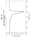
- Fig. 12 illustrates the DSC curve during temperature lowering, of wax-A according to the present invention.
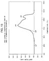
- Fig. 13 illustrates the DSC curve during temperature rise, of wax-F (a comparative example).
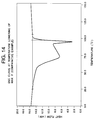
- Fig. 14 illustrates the DSC curve during temperature lowering, of wax-F (a comparative example).
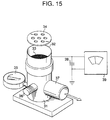
- Fig. 15 illustrates an apparatus for measuring quantity of triboelectricity of toner.
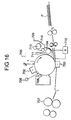
- Fig. 16 is a diagrammatic view to illustrate an electrophotographic apparatus in which the magnetic developer of the present invention is used.
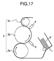
- Fig. 17 is a diagrammatic view to illustrate the method of magnetic-ink character recognition of the present invention.
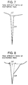
- Fig. 18 is a view to illustrate "ON-US" symbols printed as MICR characters for evaluating fine-line reproduction.
- Fig. 19 illustrates a signal waveform of "ON-US" symbols shown in Fig. 18.
- the present invention is concerned with a magnetic developer comprising a magnetic toner containing at least a binder resin, a magnetic material and a hydrocarbon wax.
- the characteristic feature is that the magnetic toner satisfies the following properties, that is, in the DSC curve measured using a differential scanning calorimeter, the onset temperature of an endothermic peak is 105°C or below and an endothermic peak temperature is within the range of from 100°C to 200°C during temperature rise, and an exothermic peak temperature is within the range of from 62°C to 75°C and the exothermic peak intensity ratio is 5 ⁇ 10 -3 or more during temperature lowering. Its use in combination with a magnetic material having specific magnetic properties as described later can achieve the objects previously stated.
- Thermal behavior of the toner can be shown by measuring the toner using a differential scanning calorimeter and analysing the data. More specifically, heat flow (heat absorption and liberation) of the toner and changes in condition of the toner can be known from the data. For example, it is possible to know the probability of offset phenomenon, the influence of the heat on the toner during storage or actual use, e.g., blocking resistance, and the influence of the temerature rise on developability.
- the present invention is characterized in that the onset temperature of an endothermic peak during temperature rise is 105°C or below, and preferably in the range of from 90 to 102°C. This brings about a superior low-temperature fixing performance. If the onset temperature is higher than 105°C, the temperature at which the plastic change immediatedly occurs becomes higher causing deterioration in low-temperature offset resistance and fixing performance.
- the present invention is also characterized in that the endothermic peak temperature during temperature rise is within the range of from 100 to 120°C, and preferably from 102 to 115°C.
- the endothermic peak temperature during temperature rise is within the range of from 100 to 120°C, and preferably from 102 to 115°C.
- this endothermic peak temperature is lower than 100°C, a plasticizing effect due to the wax melting is exerted at a low temperature resulting in considerable decrease in mechanical strength of the binder resin.
- the release effect is exerted with the decrease in mechanical strength of the binder resin causing smearing of MICR characters when they rub against the magnetic head of the MICR reader-sorter as well as the contamination of the magnetic head.
- endothermic peaks may be present in a temperature region higher than 120°C. In that case, however, a peak should be present in the region not higher than 120°C. Otherwise, the wax may have an excessively high melting temperature, which means increased releasability from the paper in MICR printing, causing falling-off of MICR characters when rubbed against the magnetic head when the MICR printed paper is passed through an MICR reader-sorter, undesirably resulting in reading error.
- the observed exothermic peaks are ascribable to transition, solidification and crystallization of the wax components.
- the present invention is characterized in that the exothermic peak observed during temperature lowering is within the range of from 62 to 75°C, and preferably from 65 to 72°C. This brings about a good MICR performance. If this exothermic peak temperature is higher than 75°C, the melting temperature of the wax is excessively high, tending to cause falling-off of MICR characters when rubbed against the magnetic head while the MICR printed paper is passed through an MICR reader-sorter.
- the plasticizing effect on the binder resin may last to a low temperature, undesirably causing smearing of MICR characters when the MICR-printed paper is passed through an MICR reader-sorter as well as the contamination of the magnetic head of the MICR reader-sorter.
- the present invention is characterized in that the intensity ratio of the exothermic peak observed during temperature lowering is 5 ⁇ 10 -3 or more, preferably 10 ⁇ 10 -3 or more, and more preferably 15 ⁇ 10 -3 or more.
- this exothermic peak intensity ratio is less than 5 ⁇ 10 -3 , the toner is undesirably liable to cause smearing of MICR characters when rubbed against the magnetic head of an MICR reader-sorter as well as the contamination of the magnetic head of the MICR reader-sorter.
- peaks may be present in other region not lower than 75°C.
- DSC measurement in the present invention the heat flow of the toner is measured and its behavior is observed.
- the measurement must be made using a differential scanning calorimeter of a high-precision internal heating input-compensating type.
- DSC-7 manufactured by Parkin Elmer Co., can be used as a measuring device for such purpose.
- the measurement is made according to ASTM D3418-82.
- the DSC curve used in the present invention is the DSC curve measured when temperature is raised once to take a previous history and thereafter temperature is lowered and raised again at a temperature rate of 10°C/min. Each temperature is defined as follows:
- Rising temperature (LP) of a peak is defined as a temperature at which the peak curve clearly separates from the base line. More specifically, a temperature at which the differential of the peak curve begins to increase, or a temperature at which the differentialof the peak curve turns from negative to positive. (Figs. 1, 3 to 6 show some examples.)
- Onset temperature (OP) of a peak is defined as a temperature at which a tangent line drawn through a point at which the differential value of the curve is extreme, intersects the base line. (Fig. 1 shows an example).
- Peak temperature (PP) is a peak top temperature of the highest peak in the region of 120°C or below.
- Exothermic peak temperature is a peak top temperature.
- Exothermic peak intensity ratio is defined as ⁇ H/ ⁇ T wherein ⁇ T represents a temperature difference between the intersections of the base line and two tangent lines of the curve, each tangent line drawn through the point at which the differential of the curve is extreme in front or in the rear of the peak top respectively; and ⁇ H represents a height per unit weight from the base line to the peak top (mW/mg, a value obtained by dividing the measured peak height, by the weight of the measured sample). (Figs. 2 and 7 to 10 show specific examples of ⁇ H and ⁇ T.) Namely, when this value is large, it means that the peak is sharp.
- the hydrocarbon wax used in the present invention is a hydrocarbon wax prepared by extraction fractionation of a specific component from a material such as (i) a low-molecular-weight alkylene polymer obtained by radical polymerization of an alkylene under a high pressure or by polymerization thereof under a low pressure in the presence of a Ziegler catalyst, (ii) an alkylene polymer obtained by thermal decomposition of a high-molecular-weight alkylene polymer or (iii) a synthetic hydrocarbon obtained by hydrogenating the distillation residue of hydrocarbons prepared by the Arge process from a synthesis gas comprised of carbon monoxide and hydrogen.
- a material such as (i) a low-molecular-weight alkylene polymer obtained by radical polymerization of an alkylene under a high pressure or by polymerization thereof under a low pressure in the presence of a Ziegler catalyst, (ii) an alkylene polymer obtained by thermal decomposition of a high-molecular-weight alkylene poly
- the hydrocarbon wax is fractionated by a fractional crystallization system utilizing press-sweating, solvent dewaxing or vacuum distillation. That is, the hydrocarbon wax include those obtained by removing low-molecular-weight components, those obtained by extracting low-molecular-weight components, or those obtained by further removing low-molecular-weight components from these, using any of these processes.
- the hydrocarbons serving as a matrix, may include i) hydrocarbons synthesized by reacting carbon monoxide with hydrogen in the presence of metal oxide type catalyst (usually two or more kinds of catalysts), as exemplified by hydrocarbons of about several hundred carbon atoms (end products are formed by finally carrying out hydrogenation) obtained by the Synthol method, the Hydrocol process (making use of a fluidized catalyst bed) or the Arge process (making use of a fixed catalyst bed), the latter provides waxy hydrocarbons in a large quantity, and ii) hydrocarbons obtained by polymerizing alkylenes such as ethylene in the presence of a Ziegler catalyst, all of which are preferable as having less branches and being saturated long straight chain hydrocarbons.
- metal oxide type catalyst usually two or more kinds of catalysts
- the hydrocarbon wax may have a number average molecular weight (Mn) of preferably from 550 to 1,200, and more preferably from 600 to 1,000, a weight average molecular weight (Mw) of preferably from 800 to 3,600, and more preferably from 900 to 3,000, and Mw/Mn of preferably not more than 3, more preferably not more than 2.5, and still more preferably not more than 2.0.
- Mn number average molecular weight
- Mw weight average molecular weight
- the hydrocarbon wax having such a molecular weight distribution can impart preferable thermal properties to the toner. More specifically, if the molecular weight corresponding to the distribution peak is smaller than the above range, the toner becomes to sensitive to thermal influence, resulting in smearing of MICR characters due to rubbing against the magnetic head when the MICR printed paper is passed through an MICR reader-sorter as well as the contamination of the magnetic head. If that molecular weight is larger than the above range, the toner may exert poor fixing performance, undesirably resulting in frequent falling-off of MICR characters when the MICR printed paper is passed through an MICR reader-sorter.
- the hydrocarbon wax may preferably have a density of 0.95 (g/cm 3 ) at 25°C and also may preferably have a penetration of 1.5 (10 -1 mm) or less, and more preferably 1.0 (10 -1 mm). If the properties are outside these ranges, the toner tends to change at low temperature, resulting in smearing of MICR characters when the MICR printed paper is passed through an MICR reader-sorter as well as the contamination of the magnetic head.
- the hydrocarbon wax should also preferably have a melt viscosity of 100 cP or less, more preferably 50 cP or less, and still more preferably 20 cP or less, at 140°C. If this melt viscosity is more than 100 cP, the toner may have poor plasticity and releasability, tending to cause smearing of MICR characters when the MICR printed paper are passed through an MICR reader-sorter and also tending to cause contamination of the magnetic head.
- the hydrocarbon wax should also preferably have a softening point of 130°C or below, and more preferably 120°C or below. If this softening point is higher than 130°C, the temperature at which the releasability is efficiently exerted becomes higher, so that the releasability becomes rather poor, tending to cause smearing of MICR characters.
- the hydrocarbon wax should preferably have an acid value of less than 2.0 mg KOH/g, and more preferably less than 1.0 mg KOH/g. If the acid value is higher than this range, its interfacial adhesion to the binder resin, a component of the toner, may become so large that the phase separation at the time of melting often becomes unsatisfactory, making good releasability difficult, causing smearing of MICR characters when the MICR printed paper is passed through an MICR reader-sorter as well as the contamination of the magnetic head of the MICR reader-sorter.
- the hydrocarbon wax should preferably be used in a content of not more than 20 parts by weight based on 100 parts of the binder resin. More preferably, it can be effectively used in a content of from 0.5 to 10 parts by weight.
- the molecular weight distribution of the hydrocarbon wax is measured by gel permeation chromatography (GPC) under the following conditions.
- Molecular weight of the sample is calculated using a molecular weight calibration curve prepared from a monodisperse polystyrene standard sample. It is calculated by further converting the value in terms of polyethylene according to a conversion formula derived from the Mark-Houwink viscosity formula.
- the needle penetration value of wax in the present invention is a value measured according to JIS K-2207. Stated specifically, it is a numerical value corresponding to the depth of penetration measured when a sample is penetrated by a needle having a diameter of about 1 mm and a conical tip with a vertical angle of 9° under a given load, and expressed in units of 0.1 mm.
- Test conditions in the present invention are as follows: Sample temperature: 25°C; load: 100 g; and penetration time: 5 seconds.
- the melt viscosity in the present invention is a value measured using a Brookfield viscometer, under conditions of a measuring temperature of 140°C, shear rate of 1.32 rpm and sample quantity of 10 ml.
- the acid value is miligrams of potassium hydroxide necessary to neutralize the acid radicals contained in 1 g of a sample (according to JIS K5920).
- the density is a value measured at 25°C according to JIS K6760, and the softening point is a value measured according to JIS K2207.
- the hydrocarbon wax satisfies the properties that, in the DSC curve measured using a differential scanning calorimeter, the onset temperature of an endothermic peak is within the range of from 50°C to 90°C, at least one endothermic peak P1 is present in a temperature range of from 90°C to 120°C and the largest exothermic peak during temperature lowering is present within ⁇ 9°C of the peak temperature of the endothermic peak P1. Its use in combination with a magnetic material having specific magnetic properties as described later can achieve the objects previously stated.
- this onset temperature of a peak during temperature rise is lower than 50°C, the wax changes at a temperature so low, that the smearing of MICR characters and the contamination of the magnetic head of the MICR reader-sorter tend to occur when the MICR printed paper is passed through an MICR reader-sorter.
- the wax may change at a temperature so high, that the falling-off of MICR characters when the MICR printed paper is passed through an MICR reader-sorter.
- the hydrocarbon wax used in the present invention is also characterized in that the endothermic peak during temperature rise is present in the range of from 90 to 120°C, preferably in the range of from 95 to 120°C, and more preferably in the range of from 97 to 115°C. That is, the wax melts in this temperature region brings about a release effect preventing the smearing of MICR characters and the contamination of the magnetic head of the MICR reader-sorter even when the MICR printed paper is repeatedly passed through an MICR reader-sorter.
- the endothermic peaks during temperature rise may also be present in a region higher than 120°C. If, however, the endothermic peaks are present only in the temperature region higher than 120°C, the wax has an excessively high melting temperature, which means , increased releasability from paper in MICR printing, which causes falling-off of MICR characters when rubbd against the magnetic head during passing through an MICR reader-sorter as well as the contamination of the magnetic head. On the other hand, if the largest endothermic peak is present at a temperature lower than 90°C, the wax behaves as if the endothermic peak is present only in this region. Therefore the endothermic peaks may be present in this region, it must be smaller than the endothermic peak present in the range of from 90 to 120°C.
- the wax is hard at the time of low temperature, rapidly melts at the time of melting and greatly decreases melting viscosity, so that a good release effect can be brought about, which prevents the falling-off of MICR characters even when the MICR printed paper is repeatedly passed through an MICR reader-sorter as well as the contamination of the magnetic head of the MICR reader-sorter.
- the maximum exothermic peak of the hydrocarbon wax should be present in the temperature region of from 85 to 115°C, and preferably from 90 to 110°C.
- each temperature is defined as follows:
- Onset temperature of a peak is defined as the lowest temperature at which the differential of the curve is extreme. Thus, the definition is different from that of the onset temperature of the toner.
- Peak temperature is the peak top temperature.
- Peak temperature is the peak top temperature of the largest peak.
- the hydrocarbon wax described above should preferably be used in a content of not more than 20 parts by weight based on 100 parts of the binder resin. More preferably, it can be effectively used in a content of from 0.5 to 10 parts by weight. It may also be used in combination with other waxes.
- the magnetic material used together in the magnetic toner having the specific thermal properties described above or the magnetic toner containing the hydrocarbon wax having the specific thermal properties described above has the constitution as described below.
- the magnetic material according to the present invention may preferably have an average particle diameter of from 0.1 to 0.6 ⁇ m, and should more preferably have an average particle diameter of from 0.15 to 0.4 ⁇ m.
- the average particle diameter is determined in the following way: An photograph of a sample is taken by 2,000 magnification using a scanning electron microscope, and the length (major axis) of 100 to 200 particles are measured at random and an average value thereof is calculated.
- the magnetic material used in the magnetic developer of the present invention has a residual magnetization ⁇ r in the range of 12 ⁇ ⁇ r ⁇ 30 emu/g, and preferably in the range of 14 ⁇ ⁇ r ⁇ 28 emu/g, in a magnetic field of 10,000 oersteds.
- a magnetic material having a residual magnetization ⁇ r of more than 30 emu/g tends to bring about a low image density as well as the fog phenomenon, therefore resulting in considerable decrease in the recognition rate of MICR characters printed with such a magnetic developer, as well as extremely low image quality when ordinary characters are printed.
- the magnetic material according to the present invention has a coercive force Hc in the range of 130 ⁇ Hc ⁇ 300 oersteds, and preferably in the range of 140 ⁇ Hc ⁇ 280 oersteds, in a magnetic field of 10,000 oersteds.
- a magnetic material having a corecive force Hc of less than 130 oersteds brings about a high image density but on the other hand a poor fine-line reproduction, undesirably causing a decrease in the recognition rate when MICR characters are printed.
- a magnetic material having a coercive force Hc of more than 300 makes it difficult for the magnetic developer to be uniformly speread on the developing sleeve, undesirably causing a decrease in image density or an uneven density.
- the magnetic toner should contain the magnetic material preferably in an amount of from 40 to 120 parts by weight, and more preferably from 50 to 110 parts by weight, based on 100 parts by weight of the binder resin.
- the magnetic material used in the present invention may preferably be produced by synthesis carried out by the wet process using an aqueous solution containing Fe 2+ , i.e., ferrous sulfate as a starting material, followed by oxidation and reduction at temperatures of 200°C or above. More specifically, it is produced by the above wet process, followed by thermal oxidation and then thermal reduction at temperatures of 200°C or above.
- the thermal oxidation may preferably be carried out at 500 to 900°C under aeration of oxidizing gas such as air, and then the thermal reduction may preferably be carried out at 250 to 550°C under aeration of reducing gas such as hydrogen and/or carbon monoxide.
- a charge control agent may preferably be used by compounding it into toner particles (internal addition) or blending it with toner particles (external addition).
- a positive charge control agent usable in the present invention may include Nigrosine and products modified with a fatty acid metal salt; quaternary ammonium salts such as tributylbenzylammonium 1-hydroxy-4-naphthoslulfonate and tetrabutylammonium teterafluoroborate; diorganotin oxides such as dibutyltin oxide, dioctyltin oxide and dicyclohexyltin oxide; and diorganotin borates such as dibutyltin borate, dioctyltin borate and dicyclohexyltin borate; any of which may be used alone or in combination of two or more kinds.
- Nigrosine type or quaternary ammonium salt type charge control agents may particularly preferably be used.
- organic metal complexes of monoazo dyes, or salts thereof, and metal complexes of salicylic acid, alkyl salicylic acids, dialkyl salicylic acids or naphthoic acid, or salts thereof, are preferably used.
- the charge control agents described above may preferably be used in the form of fine particles.
- the charge control agent may preferably have a number average particle diameter of specifically 4 ⁇ m or less, and more preferably 3 ⁇ m or less.
- such a charge control agent When internally added to the toner, such a charge control agent may preferably be used in an amount of from 0.1 part to 10 parts by weight, and more preferably from 0.1 part to 5 parts by weight, based on 100 parts by weight of the binder resin.
- the magnetic developer of the present invention may preferably have fine silica powder.
- the fine silica powder here includes anhydrous silicon dioxide (colloidal silica) as well as a silicate such as aluminum silicate, sodium silicate, potassium silicate, magnesium silicate or zinc silicate.
- a silicate such as aluminum silicate, sodium silicate, potassium silicate, magnesium silicate or zinc silicate.
- a fine silica powder having a surface specific area, as measured by the BET method using nitrogen absorption, in the range of from 70 to 300 m 2 /g can give good results.
- the fine silica powder should preferably be used in an amount of from 0.2 part to 1.6 parts by weight, and more preferably from 0.4 part to 1.4 parts by weight, based on 100 parts by weight of the magnetic toner.
- a positively chargeable fine silica powder may more preferably be added for the purpose of preventing wear of toner or preventing contamination or damage of sleeve surface, since the charge stability also is not damaged.
- the positively chargeable fine silica powder there are a method in which the untreated fine silica powder described above is treated with a silicone oil having an organo group having at least one nitrogen atom on its side chain, or a method to treat with a nitrogen-containing silane coupling agent, or a method to treat with both of these.
- a fine silica powder having a triboelectricity of from - 100 ⁇ c/g to -300 ⁇ c/g may preferably be used.
- a fine silica powder having a triboelectricity of less than - 100 ⁇ c/g may decrease the triboelectricity of the developer itself, resulting in inferior humidity characteristics.
- Use of a fine silica powder of more than -300 ⁇ c/g triboelectricity may promote the memory of the developer carrying member and also may increase the influence of deteriorated silica, bringing about a difficulty in running performance.
- a silica powder finer than 300 m 2 /g is not effective when added to the developer, and a silica powder coarser than 70 m 2 /g is liable to separate, often causing black dots due to segregation or agglomerates of silica.
- Triboelectric values of the fine silica powder is measured in the following way: A silica fine powder left to stand overnight in an environment of a temperature of 23.5C and a humidity of 60%RH, and 0.2 g and 9.8 g of an carrier iron powder not coated with a resin and having a main particle size at 200 to 300 meshes (e.g., EFV200/300, available from Nihon Teppun K.K.) are precisely weighed into 50 ml jars made of polyethylene respectively in the above environment, and thoroughly mixed by manually shaking in vertical direction about 50 times for about 20 seconds.
- an carrier iron powder not coated with a resin and having a main particle size at 200 to 300 meshes e.g., EFV200/300, available from Nihon Teppun K.K.
- the total weight of the measuring container 32 in this state is weighed and is expressed by W 1 (g).
- a suction device 31 made of an insulating material at least at the part coming into contact with the measuring container 32
- air is sucked from a suction opening 37 and an air-flow control valve 36 is operated to control the pressure indicated by a vacuum indicator 35 to be 250 mmHg. In this state, suction is sufficiently carried out to remove the silica by suction.
- the potential indicated by a potentiometer 39 at this time is expressed by V (volt).
- Reference numeral 38 denotes a capacitor, whose capacitance is expressed by C ( ⁇ F).
- the total weight of the measuring container after completion of the suction is also weighed and is expressed by W 2 (g).
- the magnetic toner used in the present invention may be optionally mixed with additives.
- a colorant conventionally known dyes and pigments can be used. It may usually be used in an amount of 0.5 part to 20 parts by weight based on 100 parts by weight of the binder resin.
- a lubricant as exemplified by zinc stearate, an abrasive such as cerium oxide or silicon carbide, a fluidity-providing and anti-caking agent as exemplified by aluminum oxide, and a conductivity-providing agent as exemplified by carbon black or tin oxide can be used in the magnetic developer of the present invention.
- the magnetic developer according to the present invention can be produced in the following way: A magnetic powder and a vinyl or non-vinyl type thermoplastic resin, optionally together with a pigment or dye as a coloring agent, a charge control agent and other additives, are thoroughly mixed using a mixing machine such as a ball mill, and then the mixture is melt-kneaded using a heat kneading machine such as a heating roll, a kneader or an extruder to melt the resin etc., in which a pigment or dye is then dispersed or dissolved, followed by cooling for solidification and thereafter pulverization and strict classification.
- a mixing machine such as a ball mill
- a heat kneading machine such as a heating roll, a kneader or an extruder to melt the resin etc.
- a pigment or dye is then dispersed or dissolved, followed by cooling for solidification and thereafter pulverization and strict classification.
- the surface of a photosensitive member is negatively charged by the operation of a primary corona assembly 702 (a charging means), and a digital latent image is formed by image scanning through optical image exposure 705 (slit exposure, laser beam scanning exposure).
- the latent image thus formed is reversally developed using a one-component magnetic developer 710 held in a developing assembly (a developing means) 709 equipped with a magnetic blade 711 and a developing sleeve 704 having a magnet 714 inside.
- an AC bias, a pulse bias and/or a DC bias is/are applied across a conductive substrate of a photosensitive drum (a photosensitive member) 1 and the developing sleeve 702 through a bias applying means 712.
- a transfer paper P is fed and delivered to the transfer zone, where the transfer paper P is charged by means of a secondary corona assembly (a transfer means) 703 from its back surface (the surface opposite to the photosensitive drum), so that the developed image (a toner image) formed on the surface of the photosensitive drum is electrostatically transferred to the transfer paper P.
- the transfer paper P separated from the photosensitive drum 701 is subjected to fixing using a heat-pressure roller fixing assembly 707 so that the toner image on the transfer paper can be fixed.
- the one-component developer remaining on the photosensitive drum 1 after the transfer step is removed by the operation of a cleaning assembly (a cleaning means) 708 having a cleaning blade. After the cleaning, the residual charges on the photosensitive drum 1 is eliminated by erase exposure 706, and thus the procedure again starts from the charging step using the primary corona assembly 702.
- An electrostatic latent image bearing member (the photosensitive drum) comprises a photosensitive layer and a conductive substrate, and is rotated in the direction of an arrow.
- the developing sleeve 704 a non-magnetic cylinder, which is a toner carrying member, is rotated so as to move in the same direction as the direction in which the electrostatic latent image bearing member is rotated.
- a multi-polar permanent magnet (a magnet roll) serving as a magnetic field generating means is provided in an unrotatable state.
- the one-component insulating magnetic developer 710 held in the developing assembly 709 is spread on the surface of the non-magnetic cylindrical developing sleeve, and, for example, negative triboelectric charges are imparted to toner particles because of the friction between the surface of the sleeve 704 and the toner particles.
- a magnetic doctor blade 711 made of iron is disposed opposingly to one of the magnetic pole positions of the multi-polar permanent magnet, in proximity (with a space of 50 ⁇ m to 500 ⁇ m) to the surface of the cylinder.
- the thickness and the uniformity of the developer layer can be controlled (from 30 ⁇ m to 300 ⁇ m) so that the developer layer thinner than the gap between the electrostatic latent image bearing member 1 and the toner carrying member 704 in the developing zone can be formed on the sleeve in a non-contact state.
- the rotational speed of this toner carrying member 704 may preferably be regulated so that the peripheral speed of the sleeve can be substantially equal or close to the speed of the peripheral speed of the surface on which electrostatic images are retained.
- a permanent magnet may be used in place of iron to form an opposing magnetic pole.
- the AC bias or pulse bias may be applied through the bias means 712, across the toner carrying member 704 and the surface on which electrostatic images are retained.
- This AC bias may have a frequency (f) of 200 Hz to 4,000 Hz, and a Vpp of 500 V to 3,000 V.
- the toner particles are moved in the developing zone to the side of the electrostatic image by the electrostatic force of the electrostatic image retaining surface and the action of the AC bias or pulse bias.
- an elastic blade made of an elastic material such as silicone rubber may be used so that the layer thickness of the developer layer can be controlled by pressure and the toner can be thereby spread on the developer carrying member.
- plural components selected from among the constituents such as the above photosensitive member, developing means and cleaning means may be integrally joined as one device unit, so that the unit is detachable from the body of the apparatus.
- the developing means and the photosensitive member may be integrally supported to form one unit detachable from the main body of the apparatus using a guide means such as a rail provided in the body of the apparatus.
- the above device unit may be so constituted as to be joined together with the charging means and/or the cleaning means.
- the optical image exposure L is carried out by irradiation with light reflected from, or transmitted through, an original, or by the scanning of a laser beam, the driving of an LED array or the driving of a liquid crystal shutter array according to signals obtained by reading an original and converting the information into signals.
- Fig. 17 illustrates an apparatus used in the process of magnetic-ink character recognition of the present invention.
- Reference numeral 1 denotes a hopper that holds recording paper P; 2, a transport means having rollers 2a, 2b and 2c; 3, a writing head that imparts magnetism to toner images on the recording paper; and 4, a reading head serving as a reading means for reading the magnetism thus imparted.
- Recording paper P having ink symbols (ON-US characters) as shown in Fig. 18, formed by a magnetic toner is transported from the hopper 1 through the rollers 2a, 2b and 2c of the transport means 2, and magnetism is imparted to the ink symbols by means of the writing head 3.
- the magnetism imparted to the ink symbols is read by the reading head 4 and the proper waveform of the ink symbols is recognized.
- the specific hydrocarbon wax is incorporated in the magnetic developer so that the magnetic developer can be endowed with preferable thermal properties.
- its use in combination with the magnetic material having the specific magnetic properties brings about the following good effects.
- the present invention can provide a magnetic developer that may cause no smearing or falling-off of MICR characters even when the MICR printed paper is repeatedly passed through an MICR reader-sorter, and a method of magnetic-ink character printed with such a magnetic developer.
- the present invention can provide a magnetic developer that may cause no soil or contamination of the magnetic head of an MICR reader-sorter even when the MICR printed paper is repeatedly passed through the MICR reader-sorter, and a method of magnetic-ink character printed with such a magnetic developer.
- the present invention can provide a magnetic developer that can form a toner image with superior resolution, gradation and fine-line reproduction even in an image forming apparatus in which a latent image is formed according to digital image signals and the latent image is developed by a reversal development system, and a method of magnetic-ink character printed with such a magnetic developer.
- the present invention can provide a magnetic developer that can show a superior recognition rate when used in MICR printing utilizing an electrophotographic printer, and a method of magnetic-ink character printed with such a magnetic developer.
- the present invention can provide a magnetic developer that may cause no decrease in the recognition rate even when the MICR printed paper is repeatedly passed through an MICR reader-sorter, and a method of magnetic-ink character printed with such a magnetic developer.
- the present invention can provide a magnetic developer that can achieve superior fine-line reproduction and resolution, and can faithfully reproduce MICR characters according to the standard, and a method of magnetic-ink character printed with such a magnetic developer.
- Hydrocarbon waxes A to H used in the present invention were prepared in the following way.
- wax F A hydrocarbon wax synthesized by the Arge process from a synthesis gas comprised of carbon monoxide and hydrogen was designated as wax F (a comparative example), from which wax A (the present invention), wax B (the present invention) and wax C (the present invention) were obtained by fractional crystallization.
- wax H a comparative example
- wax D the present invention
- Wax I (a comparative example) having a higher molecular weight than that in the polymerization carried out to synthesize wax H was obtained, from which low-molecular-weight components were extracted by fractional crystallization to give wax E (the present invention).
- a magnetic material was synthesized by the wet process using ferrous sulfate as a starting material, followed by thermal oxidation carried out at 750°C under air flow for 2 hours, and then thermal reduction carried out at 350°C under aeration of hydrogen-nitrogen mixed gas for 3 hours.
- magnetic material A as shown in Table 4 was prepared.
- Magnetic materials B and C as shown in Table 4 were each prepared by the wet process using ferrous sulfate as a starting material.
- Styrene/acrylic acid copolymer 100 parts Magnetic material A (average particle diameter: 0.24 ⁇ m; residual magnetization ⁇ r in magnetic field of 10,000 oersteds: 16.8 emu/g; coercive force Hc: 189 oersteds) 50 parts wax A 5 parts Chromium complex of monoazo dye 1 part
- the above materials were melt-kneaded using a twin-screw extruder heated to 130°C, followed by cooling.
- the resulting kneaded product was crushed using a hammer mill, and the crushed product was pulverized using a jet mill.
- the pulverized product thus obtained was classified using a fixed wall type air classifier and then fine powder and coarse powder were simultaneously strictly classifed using a multi-division classifier utilizing the Coanda effect (Elbow Jet Classifier, manufactured by Nittetsu Mining Co., Ltd.).
- a black fine powder (magnetic toner 1) with a volume average particle diameter of 12.3 ⁇ m was obtained.
- Magnetic developer (1) Based on 100 parts of the above magnetic toner, 0.5 part of negatively chargeable fine silica powder was added, followed by thorough blending to give magnetic developer (1) according to the present invention.
- Results of DSC measurement on this magnetic toner 1 are shown in Table 5, and the DSC curve during temperature rise of the magnetic toner 1 and the DSC curve during temperature lowering thereof are shown in Fig. 1 and Fig. 2, respectively.
- the magnetic developer (1) was set in its device unit to carry out image reproduction. As a result, sharp images were obtained. According to those prescribed in JIS C 6251-1980, MICR characters were printed on 1,000 sheets. As a result, the images obtained had a superior fine-line reproduction. On these 1,000 sheet prints, magnetism was imparted to the printed MICR characters and also the magnetism of the characters was read using a commercially available MICR reader-sorter (3890 Type, manufactured by IBM), to examine accuracy (rate of misread) in magnetic-ink character recognition. As a result, the rate of misread was as good as 1.8%. After passing through the MICR reader-sorter, none of smearing and falling-off of the MICR characters nor contamination of the magnetic head of the MICR reader-sorter were seen.
- MICR reader-sorter 3890 Type, manufactured by IBM
- MICR characters were printed according to JIS-C6251-1980, and magnetic signal intensity of ON-US symbols as shown in Fig. 18 was measured to obtain a signal waveform as shown in Fig. 19. On the basis of the waveform obtained, the fine-line reproduction was judged.
- the image density was measured using a Macbeth reflection densitometer, and judged from average density of 10 sheets of image samples.
- Magnetic toners 2 to 5 were prepared in the same manner as in Example 1 except that waxes B to E were respectively used. Magnetic developers (2) to (5) were also prepared in the same way. Results of DSC measurement on these magnetic toners 2 to 5 are shown in Table 5.
- Comparative magnetic toners 1 to 3 were prepared in the same manner as in Example 1 except that waxes F to I were respectively used. Magnetic developers (6) to (8) were also prepared in the same way. Results of DSC measurement on these comparative magnetic toners 1 to 3 are shown in Table 5.
- Comparative magnetic toner 4 was prepared in the same manner as in Example 1 except that no wax was used. Magnetic developer (9) was also prepared in the same way. Results of DSC measurement on this comparative magnetic toner 4 are shown in Table 5. The endothermic peak thereof is ascribed to the binder resin, which is also seen in other magnetic developers.
- Comparative magnetic toner 5 was prepared in the same manner as in Example 1 except that magnetic material A was replaced with magnetic material B. Magnetic developer (10) was also prepared in the same way. Results of DSC measurement on this comparative magnetic toner 5 are shown in Table 5.
- Comparative magnetic toner 6 was prepared in the same manner as in Example 1 except that magnetic material A was replaced with magnetic material C. Magnetic developer (11) was also prepared in the same way. Results of DSC measurement on this comparative magnetic toner 6 are shown in Table 5.
- Comparative magnetic toner 7 was prepared in the same manner as in Example 1 except that magnetic material A was replaced with magnetic material B and also no wax was used. Magnetic developer (12) was also prepared in the same way. Results of DSC measurement on this comparative magnetic toner 7 are shown in Table 5.
Claims (59)
- Magnetischer Entwickler, der einen magnetischen Toner umfaßt, der mindestens ein Bindemittelharz, ein magnetisches Material und ein Kohlenwasserstoffwachs enthält,wobei der erwähnte magnetische Toner derartige Eigenschaften hat, daßeine DSC-Kurve des Toners, die unter Anwendung eines Kalorimeters mit Differentialabtastung gemessen wird, dadurch gekennzeichnet ist, daß die Anfangstemperatur eines endothermen Peaks bei steigender Temperatur bei 105 °C oder darunter liegt und seine Peaktemperatur im Bereich von 100 °C bis 120 °C liegt und daß die Peaktemperatur eines exothermen Peaks bei fallender Temperatur im Bereich von 62 °C bis 75 °C liegt und sein Peakintensitätsverhältnis 5 × 10⁻³ oder mehr beträgt; unddas erwähnte magnetische Material derartige Eigenschaften hat, daßin einem Magnetfeld von 10.000 Oersted die Remanenz or im Bereich von 12 emE/g bis 30 emE/g liegt und die Koerzitivkraft Hc im Bereich von 130 Oersted bis 300 Oersted liegt.
- Magnetischer Entwickler nach Anspruch 1, bei dem die Anfangstemperatur des endothermen Peaks im Bereich von 90 °C bis 102 °C liegt und die Peaktemperatur des endothermen Peaks im Bereich von 102 °C bis 115 °C liegt.
- Magnetischer Entwickler nach Anspruch 1, bei dem die Peaktemperatur des exothermen Peaks im Bereich von 65 °C bis 72 °C liegt und das Peakintensitätsverhältnis des exothermen Peaks 10 × 10-3 oder mehr beträgt.
- Magnetischer Entwickler nach Anspruch 3, bei dem das Peakintensitätsverhältnis des exothermen Peaks 15 × 10-3 oder mehr beträgt.
- Magnetischer Entwickler nach Anspruch 1, bei dem das erwähnte Kohlenwasserstoffwachs durch Extraktionsfraktionierung aus einem Kohlenwasserstoff erhalten wird, der durch Umsetzung von Kohlenmonoxid mit Wasserstoff in Gegenwart eines Katalysators des Metalloxidtyps synthetisiert worden ist.
- Magnetischer Entwickler nach Anspruch 5, bei dem das erwähnte Kohlenwasserstoffwachs durch das Synthol-Verfahren erhalten wird.
- Magnetischer Entwickler nach Anspruch 5, bei dem das erwähnte Kohlenwasserstoffwachs durch das Hydrocol-Verfahren erhalten wird.
- Magnetischer Entwickler nach Anspruch 5, bei dem das erwähnte Kohlenwasserstoffwachs durch das Arge-Verfahren erhalten wird.
- Magnetischer Entwickler nach Anspruch 5, bei dem das erwähnte Kohlenwasserstoffwachs durch Extraktionsfraktionierung aus einem Kohlenwasserstoff erhalten wird, der durch Polymerisation eines Alkylens in Gegenwart eines Ziegler-Katalysators gebildet worden ist.
- Magnetischer Entwickler nach Anspruch 1, bei dem das erwähnte Kohlenwasserstoffwachs eine anzahlgemittelte Molmasse (Mn) von 550 bis 1200, eine massegemittelte Molmasse (Mw) von 800 bis 3600 und einen Mw/Mn-Wert von nicht mehr als 3 hat.
- Magnetischer Entwickler nach Anspruch 1, bei dem das erwähnte Kohlenwasserstoffwachs eine anzahlgemittelte Molmasse (Mn) von 600 bis 1000, eine massegemittelte Molmasse (Mw) von 900 bis 3000 und einen Mw/Mn-Wert von nicht mehr als 2,5 hat.
- Magnetischer Entwickler nach Anspruch 1, bei dem das erwähnte Kohlenwasserstoffwachs eine Dichte von 0,95 (g/cm3) oder mehr bei 25 °C hat.
- Magnetischer Entwickler nach Anspruch 1, bei dem das erwähnte Kohlenwasserstoffwachs eine Penetration von 1,5 (10-1 mm) oder weniger hat.
- Magnetischer Entwickler nach Anspruch 1, bei dem das erwähnte Kohlenwasserstoffwachs eine Erweichungstemperatur (Mp) von 130 °C oder darunter hat.
- Magnetischer Entwickler nach Anspruch 1, bei dem der erwähnte magnetische Toner das Kohlenwasserstoffwachs in einer Menge von nicht mehr als 20 Masseteilen, bezogen auf 100 Masseteile des Bindemittelharzes, enthält.
- Magnetischer Entwickler nach Anspruch 1, bei dem der erwähnte magnetische Toner das Kohlenwasserstoffwachs in einer Menge von 0,5 Masseteilen bis 10 Masseteilen, bezogen auf 100 Masseteile des Bindemittelharzes, enthält.
- Magnetischer Entwickler nach Anspruch 1, bei dem das erwähnte magnetische Material in einem Magnetfeld von 10.000 Oersted eine Remanenz or im Bereich von 14 emE/g bis 28 emE/g und eine Koerzitivkraft Hc im Bereich von 140 Oersted bis 280 Oersted hat.
- Magnetischer Entwickler nach Anspruch 1, bei dem der erwähnte magnetische Toner das magnetische Material in einer Menge von 40 Masseteilen bis 120 Masseteilen, bezogen auf 100 Masseteile des Bindemittelharzes, enthält.
- Magnetischer Entwickler nach Anspruch 1, bei dem der erwähnte magnetische Toner das magnetische Material in einer Menge von 50 Masseteilen bis 110 Masseteilen, bezogen auf 100 Masseteile des Bindemittelharzes, enthält.
- Magnetischer Entwickler nach Anspruch 1, wobei der erwähnte magnetische Entwickler ein feines Siliciumdioxidpulver in einer Menge von 0,2 Masseteilen bis 1,6 Masseteilen, bezogen auf 100 Masseteile des magnetischen Toners, enthält.
- Magnetischer Entwickler nach Anspruch 1, wobei der erwähnte magnetische Entwickler ein feines Siliciumdioxidpulver in einer Menge von 0,4 Masseteilen bis 1,4 Masseteilen, bezogen auf 100 Masseteile des magnetischen Toners, enthält.
- Magnetischer Entwickler nach Anspruch 1, bei dem das erwähnte magnetische Material einen mittleren Teilchendurchmesser von 0,1 µm bis 0,6 µm hat.
- Magnetischer Entwickler nach Anspruch 1, bei dem das erwähnte Kohlenwasserstoffwachs die Eigenschaften erfüllt, daß in einer DSC-Kurve, die unter Anwendung eines Kalorimeters mit Differentialabtastung gemessen wird, die Anfangstemperatur eines endothermen Peaks im Bereich von 50 °C bis 90 °C liegt, in einem Temperaturbereich von 90 °C bis 120 °C mindestens ein endothermer Peak P1 vorhanden ist und ein maximaler exothermer Peak bei fallender Temperatur in dem Bereich vorhanden ist, dessen Grenzen bei "Peaktemperatur des endothermen Peaks P1 ± 9 °C" liegen, wobei auf endotherme Peaks bei steigender Temperatur und exotherme Peaks bei fallender Temperatur Bezug genommen wird.
- Magnetischer Entwickler nach Anspruch 23, bei dem die DSC-Kurve des Kohlenwasserstoffwachses die Anfangstemperatur des endothermen Peaks im Bereich von 55 °C bis 90 °C hat und in einem Temperaturbereich von 95 °C bis 120 °C mindestens ein endothermer Peak vorhanden ist.
- Magnetischer Entwickler nach Anspruch 24, bei dem die DSC-Kurve des Kohlenwasserstoffwachses in einem Temperaturbereich von 97 °C bis 115 °C mindestens einen endothermen Peak hat.
- Magnetischer Entwickler nach Anspruch 23, bei dem die DSC-Kurve des Kohlenwasserstoffwachses den maximalen exothermen Peak in dem Bereich hat, dessen Grenzen bei "Peaktemperatur des endothermen Peaks P1 ± 7 °C" liegen.
- Magnetischer Entwickler nach Anspruch 23, wobei bei dem erwähnten Kohlenwasserstoffwachs der maximale exotherme Peak beim Temperaturabfall in dem Bereich vorhanden ist, dessen Grenzen bei "Peaktemperatur des endothermen Peaks P1 beim Temperaturanstieg ± 5 °C" liegen.
- Magnetischer Entwickler nach Anspruch 1, wobei der erwähnte magnetische Entwickler angewendet wird, um ein (Schrift)zeichen zu drucken, das in einem Magnetzeichenerkennungssystem angewendet wird, in dem Daten, die einem magnetischen (Schrift)zeichen entsprechen, unter Anwendung eines Magnetzeichenlesers gelesen werden.
- Magnetischer Entwickler, der einen magnetischen Toner umfaßt, der mindestens ein Bindemittelharz, ein magnetisches Material und ein Kohlenwasserstoffwachs enthält, wobeidas erwähnte Kohlenwasserstoffwachs die Eigenschaften erfüllt, daß in einer DSC-Kurve, die unter Anwendung eines Kalorimeters mit Differentialabtastung gemessen wird, die Anfangstemperatur eines endothermen Peaks im Bereich von 50 °C bis 90 °C liegt, in einem Temperaturbereich von 90 °C bis 120 °C mindestens ein endothermer Peak P1 vorhanden ist und ein maximaler exothermer Peak bei fallender Temperatur in dem Bereich vorhanden ist, dessen Grenzen bei "Peaktemperatur des endothermen Peaks P1 ± 9 °C" liegen, wobei auf endotherme Peaks bei steigender Temperatur und exotherme Peaks bei fallender Temperatur Bezug genommen wird, unddas erwähnte magnetische Material in einem Magnetfeld von 10.000 Oersted eine Remanenz or im Bereich von 12 emE/g bis 30 emE/g und eine Koerzitivkraft Hc im Bereich von 130 Oersted bis 300 Oersted hat.
- Magnetischer Entwickler nach Anspruch 29, bei dem die DSC-Kurve des Kohlenwasserstoffwachses die Anfangstemperatur des endothermen Peaks im Bereich von 55 °C bis 90 °C hat und in einem Temperaturbereich von 95 °C bis 120 °C mindestens ein endothermer Peak vorhanden ist.
- Magnetischer Entwickler nach Anspruch 30, bei dem die DSC-Kurve des Kohlenwasserstoffwachses in einem Temperaturbereich von 97 °C bis 115 °C mindestens einen endothermen Peak hat.
- Magnetischer Entwickler nach Anspruch 29, bei dem die DSC-Kurve des Kohlenwasserstoffwachses den maximalen exothermen Peak in dem Bereich hat, dessen Grenzen bei "Peaktemperatur des endothermen Peaks P1 ± 7 °C" liegen.
- Magnetischer Entwickler nach Anspruch 29, bei dem die DSC-Kurve des Kohlenwasserstoffwachses den maximalen exothermen Peak in dem Bereich hat, dessen Grenzen bei "Peaktemperatur des endothermen Peaks P1 ± 5 °C" liegen.
- Magnetischer Entwickler nach Anspruch 29, bei dem das erwähnte Kohlenwasserstoffwachs durch Extraktionsfraktionierung aus einem Kohlenwasserstoff erhalten wird, der durch Umsetzung von Kohlenmonoxid mit Wasserstoff in Gegenwart eines Katalysators des Metalloxidtyps synthetisiert worden ist.
- Magnetischer Entwickler nach Anspruch 34, bei dem das erwähnte Kohlenwasserstoffwachs durch das Synthol-Verfahren erhalten wird.
- Magnetischer Entwickler nach Anspruch 34, bei dem das erwähnte Kohlenwasserstoffwachs durch das Hydrocol-Verfahren erhalten wird.
- Magnetischer Entwickler nach Anspruch 34, bei dem das erwähnte Kohlenwasserstoffwachs durch das Arge-Verfahren erhalten wird.
- Magnetischer Entwickler nach Anspruch 29, bei dem das erwähnte Kohlenwasserstoffwachs durch Extraktionsfraktionierung aus einem Kohlenwasserstoff erhalten wird, der durch Polymerisation eines Alkylens in Gegenwart eines Ziegler-Katalysators gebildet worden ist.
- Magnetischer Entwickler nach Anspruch 29, bei dem das erwähnte Kohlenwasserstoffwachs eine anzahlgemittelte Molmasse (Mn) von 550 bis 1200, eine massegemittelte Molmasse (Mw) von 800 bis 3600 und einen Mw/Mn-Wert von nicht mehr als 3 hat.
- Magnetischer Entwickler nach Anspruch 29, bei dem das erwähnte Kohlenwasserstoffwachs eine anzahlgemittelte Molmasse (Mn) von 600 bis 1000, eine massegemittelte Molmasse (Mw) von 900 bis 3000 und einen Mw/Mn-Wert von nicht mehr als 2,5 hat.
- Magnetischer Entwickler nach Anspruch 29, bei dem das erwähnte Kohlenwasserstoffwachs eine Dichte von 0,95 (g/cm3) oder mehr bei 25 °C hat.
- Magnetischer Entwickler nach Anspruch 29, bei dem das erwähnte Kohlenwasserstoffwachs eine Penetration von 1,5 (10-1 mm) oder weniger hat.
- Magnetischer Entwickler nach Anspruch 29, bei dem das erwähnte Kohlenwasserstoffwachs eine Erweichungstemperatur (Mp) von 130 °C oder darunter hat.
- Magnetischer Entwickler nach Anspruch 29, bei dem der erwähnte magnetische Toner das Kohlenwasserstoffwachs in einer Menge von nicht mehr als 20 Masseteilen, bezogen auf 100 Masseteile des Bindemittelharzes, enthält.
- Magnetischer Entwickler nach Anspruch 29, bei dem der erwähnte magnetische Toner das Kohlenwasserstoffwachs in einer Menge von 0,5 Masseteilen bis 10 Masseteilen, bezogen auf 100 Masseteile des Bindemittelharzes, enthält.
- Magnetischer Entwickler nach Anspruch 29, bei dem das erwähnte magnetische Material in einem Magnetfeld von 10.000 Oersted eine Remanenz or im Bereich von 14 emE/g bis 28 emE/g hat und in einem Magnetfeld von 10.000 Oersted eine Koerzitivkraft Hc im Bereich von 140 Oersted bis 280 Oersted hat.
- Magnetischer Entwickler nach Anspruch 29, bei dem der erwähnte magnetische Toner das magnetische Material in einer Menge von 40 Masseteilen bis 120 Masseteilen, bezogen auf 100 Masseteile des Bindemittelharzes, enthält.
- Magnetischer Entwickler nach Anspruch 29, bei dem der erwähnte magnetische Toner das magnetische Material in einer Menge von 50 Masseteilen bis 110 Masseteilen, bezogen auf 100 Masseteile des Bindemittelharzes, enthält.
- Magnetischer Entwickler nach Anspruch 29, wobei der erwähnte magnetische Entwickler ein feines Siliciumdioxidpulver in einer Menge von 0,2 Masseteilen bis 1,6 Masseteilen, bezogen auf 100 Masseteile des magnetischen Toners, enthält.
- Magnetischer Entwickler nach Anspruch 29, wobei der erwähnte magnetische Entwickler ein feines Siliciumdioxidpulver in einer Menge von 0,4 Masseteilen bis 1,4 Masseteilen, bezogen auf 100 Masseteile des magnetischen Toners, enthält.
- Magnetischer Entwickler nach Anspruch 29, bei dem das erwähnte magnetische Material einen mittleren Teilchendurchmesser von 0,1 µm bis 0,6 µm hat.
- Magnetischer Entwickler nach Anspruch 29, wobei der erwähnte magnetische Entwickler angewendet wird, um ein (Schrift)zeichen zu drucken, das in einem Magnetzeichenerkennungssystem angewendet wird, in dem Daten, die einem magnetischen (Schrift)zeichen entsprechen, unter Anwendung eines Magnetzeichenlesers gelesen werden.
- Verfahren zur Magnetzeichenerkennung, bei demein Magnetzeichen unter Verwendung eines magnetischen Entwicklers auf einen Aufzeichnungsträger gedruckt wird;das gedruckte Magnetzeichen magnetisiert wird undder Magnetismus des magnetisierten Magnetzeichens gelesen und erkannt wird;wobei der erwähnte magnetische Entwickler einen magnetischen Toner umfaßt, der mindestens ein Bindemittelharz, ein magnetisches Material und ein Kohlenwasserstoffwachs enthält;wobei der erwähnte magnetische Toner derartige Eigenschaften hat, daßeine DSC-Kurve des Toners, die unter Anwendung eines Kalorimeters mit Differentialabtastung gemessen wird, dadurch gekennzeichnet ist, daß die Anfangstemperatur eines endothermen Peaks bei steigender Temperatur bei 105 °C oder darunter liegt und seine Peaktemperatur im Bereich von 100 °C bis 120 °C liegt und daß die Peaktemperatur eines exothermen Peaks bei fallender Temperatur im Bereich von 62 °C bis 75 °C liegt und sein Peakintensitätsverhältnis 5 × 10⁻³ oder mehr beträgt; undwobei das erwähnte magnetische Material derartige Eigenschaften hat, daßin einem Magnetfeld von 10.000 Oersted die Remanenz or im Bereich von 12 emE/g bis 30 emE/g liegt und die Koerzitivkraft Hc im Bereich von 130 Oersted bis 300 Oersted liegt.
- Verfahren zur Magnetzeichenerkennung nach Anspruch 53, bei dem der erwähnte magnetische Entwickler den magnetischen Entwickler nach einem der Ansprüche 2 bis 28 umfaßt.
- Verfahren zur Magnetzeichenerkennung, bei demein Magnetzeichen unter Verwendung eines magnetischen Entwicklers auf einen Aufzeichnungsträger gedruckt wird;das gedruckte Magnetzeichen magnetisiert wird undder Magnetismus des magnetisierten Magnetzeichens gelesen und erkannt wird;wobei der erwähnte magnetische Entwickler einen magnetischen Toner umfaßt, der mindestens ein Bindemittelharz, ein magnetisches Material und ein Kohlenwasserstoffwachs enthält; wobeidas erwähnte Kohlenwasserstoffwachs die Eigenschaften erfüllt, daß in der DSC-Kurve, die unter Anwendung eines Kalorimeters mit Differentialabtastung gemessen wird, die Anfangstemperatur eines endothermen Peaks im Bereich von 50 °C bis 90 °C liegt, in einem Temperaturbereich von 90 °C bis 120 °C mindestens ein endothermer Peak P1 vorhanden ist und ein maximaler exothermer Peak bei fallender Temperatur in dem Bereich vorhanden ist, dessen Grenzen bei "Peaktemperatur des endothermen Peaks P1 ± 9 °C" liegen, wobei auf endotherme Peaks beim Temperaturanstieg und exotherme Peaks beim Temperaturabfall Bezug genommen wird, unddas erwähnte magnetische Material in einem Magnetfeld von 10.000 Oersted eine Remanenz or im Bereich von 12 emE/g bis 30 emE/g und eine Koerzitivkraft Hc im Bereich von 130 Oersted bis 300 Oersted hat.
- Verfahren zur Magnetzeichenerkennung nach Anspruch 55, bei dem der erwähnte magnetische Entwickler den magnetischen Entwickler nach einem der Ansprüche 30 bis 52 umfaßt.
- Verfahren zur Magnetzeichenerkennung nach Anspruch 53, bei dem das erwähnte Kohlenwasserstoffwachs gesättigte Kohlenwasserstoffe mit langer gerader Kette umfaßt.
- Verfahren zur Magnetzeichenerkennung nach Anspruch 55, bei dem das erwähnte Kohlenwasserstoffwachs gesättigte Kohlenwasserstoffe mit langer gerader Kette umfaßt.
- Magnetischer Entwickler nach Anspruch 1, bei dem das erwähnte Kohlenwasserstoffwachs gesättigte Kohlenwasserstoffe mit langer gerader Kette umfaßt.
Applications Claiming Priority (2)
| Application Number | Priority Date | Filing Date | Title |
|---|---|---|---|
| JP15622292 | 1992-05-25 | ||
| JP156222/92 | 1992-05-25 |
Publications (3)
| Publication Number | Publication Date |
|---|---|
| EP0572896A2 EP0572896A2 (de) | 1993-12-08 |
| EP0572896A3 EP0572896A3 (en) | 1994-06-08 |
| EP0572896B1 true EP0572896B1 (de) | 1998-01-07 |
Family
ID=15623030
Family Applications (1)
| Application Number | Title | Priority Date | Filing Date |
|---|---|---|---|
| EP93108365A Expired - Lifetime EP0572896B1 (de) | 1992-05-25 | 1993-05-24 | Magnetischer Entwickler und Verfahren zur Erkennung von Zeichen aus magnetischer Tinte |
Country Status (3)
| Country | Link |
|---|---|
| US (1) | US5952138A (de) |
| EP (1) | EP0572896B1 (de) |
| DE (1) | DE69316086T2 (de) |
Families Citing this family (11)
| Publication number | Priority date | Publication date | Assignee | Title |
|---|---|---|---|---|
| DE69426920T2 (de) * | 1993-12-29 | 2001-08-09 | Canon Kk | Toner für die Entwicklung elektrostatischer Bilder und Hitzefixierungsverfahren |
| DE69614022T2 (de) * | 1995-04-07 | 2001-11-29 | Canon Kk | Toner für die Entwicklung elektrostatischer Bilder |
| US5702859A (en) * | 1995-05-16 | 1997-12-30 | Tomoegawa Paper Co., Ltd. | Electrophotographic toner and process for the production thereof |
| US6120961A (en) * | 1996-10-02 | 2000-09-19 | Canon Kabushiki Kaisha | Toner for developing electrostatic images |
| WO1999066450A1 (en) * | 1998-06-16 | 1999-12-23 | Source Technologies, Inc. | System for concurrent check validation and micr encoding |
| WO2000070408A1 (en) * | 1999-05-17 | 2000-11-23 | Flint Ink Corporation | Liquid magnetic image character recognition developer |
| US6331372B1 (en) | 1999-10-08 | 2001-12-18 | Lexmark International, Inc. | Toner particulates comprising an ethylene propylene wax |
| US6613490B2 (en) | 2000-10-31 | 2003-09-02 | Canon Kabushiki Kaisha | Toner, image forming method and process-cartridge |
| US6610451B2 (en) * | 2000-12-26 | 2003-08-26 | Heidelberger Druckmaschinen Ag | Development systems for magnetic toners having reduced magnetic loadings |
| US6696212B2 (en) * | 2001-03-27 | 2004-02-24 | Heidelberger Druckmaschinen Ag | Single component toner for improved magnetic image character recognition |
| US7094513B2 (en) * | 2002-12-06 | 2006-08-22 | Orient Chemical Industries, Ltd. | Charge control agent and toner for electrostatic image development |
Family Cites Families (12)
| Publication number | Priority date | Publication date | Assignee | Title |
|---|---|---|---|---|
| JPS5929862B2 (ja) * | 1979-08-28 | 1984-07-24 | 日立金属株式会社 | 磁性トナ− |
| JPS58189646A (ja) * | 1982-04-01 | 1983-11-05 | Canon Inc | 磁性トナ− |
| FR2529580B1 (fr) * | 1982-06-30 | 1986-03-21 | Pechiney Aluminium | Cuve d'electrolyse pour la production d'aluminium, comportant un ecran conducteur flottant |
| JPS597379A (ja) * | 1982-07-05 | 1984-01-14 | Canon Inc | 記録装置 |
| JPH0715596B2 (ja) * | 1986-05-15 | 1995-02-22 | キヤノン株式会社 | 重合トナーの製造方法 |
| JPH0827551B2 (ja) * | 1986-10-27 | 1996-03-21 | キヤノン株式会社 | 絶縁性磁性カプセルトナ− |
| JPH07120071B2 (ja) * | 1988-02-29 | 1995-12-20 | キヤノン株式会社 | 磁性トナー |
| JPH0816789B2 (ja) * | 1989-09-05 | 1996-02-21 | 株式会社巴川製紙所 | 静電荷像現像用トナー |
| DE69118412T2 (de) * | 1990-01-19 | 1996-11-14 | Canon Kk | Toner für die Entwicklung elektrostatischer Bilder und Fixierungsverfahren |
| US5411830A (en) * | 1990-07-27 | 1995-05-02 | Canon Kabushiki Kaisha | Magnetic developer, electrophotographic apparatus and recognition method of magnetic ink character |
| JPH04166850A (ja) * | 1990-10-30 | 1992-06-12 | Canon Inc | Micrプリンター |
| KR970001393B1 (ko) * | 1991-09-11 | 1997-02-06 | 캐논 가부시기가이샤 | 정전하상 현상용 토너 및 가열정착방법 |
-
1993
- 1993-05-24 EP EP93108365A patent/EP0572896B1/de not_active Expired - Lifetime
- 1993-05-24 DE DE69316086T patent/DE69316086T2/de not_active Expired - Lifetime
-
1995
- 1995-03-30 US US08/414,053 patent/US5952138A/en not_active Expired - Lifetime
Also Published As
| Publication number | Publication date |
|---|---|
| DE69316086D1 (de) | 1998-02-12 |
| DE69316086T2 (de) | 1998-05-20 |
| EP0572896A3 (en) | 1994-06-08 |
| EP0572896A2 (de) | 1993-12-08 |
| US5952138A (en) | 1999-09-14 |
Similar Documents
| Publication | Publication Date | Title |
|---|---|---|
| EP0410482B1 (de) | Bilderzeugungsgerät | |
| EP0357454B1 (de) | Elektrophotographisches Verfahren | |
| EP0482665B1 (de) | Entwickler zur Entwicklung elektrostatischer Bilder, Bilderzeugungsverfahren, elektrographischer Apparat, Geräteeinheit und Faksimile-Apparatur | |
| US5914209A (en) | Single development toner for improved MICR | |
| US5750302A (en) | Magnetic toner for developing electrostatic image, image forming process, and process cartridge | |
| EP0606873A1 (de) | Toner zur Entwicklung elektrostatischer Bilder, Ein-/und Zwei-komponenten-Entwickler | |
| EP0572896B1 (de) | Magnetischer Entwickler und Verfahren zur Erkennung von Zeichen aus magnetischer Tinte | |
| US5124217A (en) | Magnetic image character recognition processes | |
| EP0699963B1 (de) | Magnetischer Toner, Abbilddungsverfahren | |
| EP0587540A2 (de) | Toner zur Entwicklung elektrostatischer Bilder und Bilderzeugungsverfahren | |
| EP0468525B1 (de) | Magnetischer Entwickler, elektrophotographisches Gerät und Verfahren zur Erkennung von Zeichen aus magnetischer Tinte | |
| US5710965A (en) | Developer for developing electrostatic images and image forming method | |
| US6852460B2 (en) | Toner and image forming method using the same | |
| EP0707239A1 (de) | Toner für die Entwicklung elektrostatischer Bilder, Bildherstellungsverfahren und Prozesscassette | |
| US20020106575A1 (en) | Image forming method | |
| JP3278239B2 (ja) | 磁性現像剤及び磁性インク記号認識方法 | |
| US6733940B2 (en) | Toner for magnetic ink character recognition system and non-magnetic monocomponent development method | |
| JP4085107B2 (ja) | 電子写真方法 | |
| JP3035689B2 (ja) | 磁性現像剤 | |
| JP4116694B2 (ja) | 静電潜像用磁性トナー | |
| JP2896828B2 (ja) | 磁性現像剤、画像形成装置及び装置ユニット | |
| JPH0777830A (ja) | 磁性現像剤、画像形成方法、画像形成装置及び装置ユニット | |
| JP3240363B2 (ja) | 静電荷像現像用トナー及び磁性インク記号識別方法 | |
| JPH04362954A (ja) | 磁性現像剤、装置ユニット、電子写真装置及び磁性インク記号の識別方法 | |
| JP2783658B2 (ja) | 磁性現像剤、装置ユニット及び磁性インキ記号認識方法 |
Legal Events
| Date | Code | Title | Description |
|---|---|---|---|
| PUAI | Public reference made under article 153(3) epc to a published international application that has entered the european phase |
Free format text: ORIGINAL CODE: 0009012 |
|
| AK | Designated contracting states |
Kind code of ref document: A2 Designated state(s): DE FR GB IT NL |
|
| PUAL | Search report despatched |
Free format text: ORIGINAL CODE: 0009013 |
|
| AK | Designated contracting states |
Kind code of ref document: A3 Designated state(s): DE FR GB IT NL |
|
| 17P | Request for examination filed |
Effective date: 19941025 |
|
| GRAG | Despatch of communication of intention to grant |
Free format text: ORIGINAL CODE: EPIDOS AGRA |
|
| 17Q | First examination report despatched |
Effective date: 19970218 |
|
| GRAG | Despatch of communication of intention to grant |
Free format text: ORIGINAL CODE: EPIDOS AGRA |
|
| GRAH | Despatch of communication of intention to grant a patent |
Free format text: ORIGINAL CODE: EPIDOS IGRA |
|
| GRAH | Despatch of communication of intention to grant a patent |
Free format text: ORIGINAL CODE: EPIDOS IGRA |
|
| GRAA | (expected) grant |
Free format text: ORIGINAL CODE: 0009210 |
|
| AK | Designated contracting states |
Kind code of ref document: B1 Designated state(s): DE FR GB IT NL |
|
| PG25 | Lapsed in a contracting state [announced via postgrant information from national office to epo] |
Ref country code: NL Free format text: LAPSE BECAUSE OF FAILURE TO SUBMIT A TRANSLATION OF THE DESCRIPTION OR TO PAY THE FEE WITHIN THE PRESCRIBED TIME-LIMIT Effective date: 19980107 |
|
| REF | Corresponds to: |
Ref document number: 69316086 Country of ref document: DE Date of ref document: 19980212 |
|
| ET | Fr: translation filed | ||
| ITF | It: translation for a ep patent filed |
Owner name: SOCIETA' ITALIANA BREVETTI S.P.A. |
|
| NLV1 | Nl: lapsed or annulled due to failure to fulfill the requirements of art. 29p and 29m of the patents act | ||
| PLBE | No opposition filed within time limit |
Free format text: ORIGINAL CODE: 0009261 |
|
| STAA | Information on the status of an ep patent application or granted ep patent |
Free format text: STATUS: NO OPPOSITION FILED WITHIN TIME LIMIT |
|
| 26N | No opposition filed | ||
| REG | Reference to a national code |
Ref country code: GB Ref legal event code: IF02 |
|
| PGFP | Annual fee paid to national office [announced via postgrant information from national office to epo] |
Ref country code: IT Payment date: 20090515 Year of fee payment: 17 Ref country code: FR Payment date: 20090520 Year of fee payment: 17 |
|
| REG | Reference to a national code |
Ref country code: FR Ref legal event code: ST Effective date: 20110131 |
|
| PG25 | Lapsed in a contracting state [announced via postgrant information from national office to epo] |
Ref country code: IT Free format text: LAPSE BECAUSE OF NON-PAYMENT OF DUE FEES Effective date: 20100524 |
|
| PG25 | Lapsed in a contracting state [announced via postgrant information from national office to epo] |
Ref country code: FR Free format text: LAPSE BECAUSE OF NON-PAYMENT OF DUE FEES Effective date: 20100531 |
|
| PGFP | Annual fee paid to national office [announced via postgrant information from national office to epo] |
Ref country code: GB Payment date: 20110517 Year of fee payment: 19 |
|
| PGFP | Annual fee paid to national office [announced via postgrant information from national office to epo] |
Ref country code: DE Payment date: 20110531 Year of fee payment: 19 |
|
| GBPC | Gb: european patent ceased through non-payment of renewal fee |
Effective date: 20120524 |
|
| REG | Reference to a national code |
Ref country code: DE Ref legal event code: R119 Ref document number: 69316086 Country of ref document: DE Effective date: 20121201 |
|
| PG25 | Lapsed in a contracting state [announced via postgrant information from national office to epo] |
Ref country code: GB Free format text: LAPSE BECAUSE OF NON-PAYMENT OF DUE FEES Effective date: 20120524 |
|
| PG25 | Lapsed in a contracting state [announced via postgrant information from national office to epo] |
Ref country code: DE Free format text: LAPSE BECAUSE OF NON-PAYMENT OF DUE FEES Effective date: 20121201 |