EP0482665B1 - Entwickler zur Entwicklung elektrostatischer Bilder, Bilderzeugungsverfahren, elektrographischer Apparat, Geräteeinheit und Faksimile-Apparatur - Google Patents
Entwickler zur Entwicklung elektrostatischer Bilder, Bilderzeugungsverfahren, elektrographischer Apparat, Geräteeinheit und Faksimile-Apparatur Download PDFInfo
- Publication number
- EP0482665B1 EP0482665B1 EP91118252A EP91118252A EP0482665B1 EP 0482665 B1 EP0482665 B1 EP 0482665B1 EP 91118252 A EP91118252 A EP 91118252A EP 91118252 A EP91118252 A EP 91118252A EP 0482665 B1 EP0482665 B1 EP 0482665B1
- Authority
- EP
- European Patent Office
- Prior art keywords
- developer
- toner
- electrostatic image
- bearing member
- fine
- Prior art date
- Legal status (The legal status is an assumption and is not a legal conclusion. Google has not performed a legal analysis and makes no representation as to the accuracy of the status listed.)
- Expired - Lifetime
Links
Images


Classifications
-
- G—PHYSICS
- G03—PHOTOGRAPHY; CINEMATOGRAPHY; ANALOGOUS TECHNIQUES USING WAVES OTHER THAN OPTICAL WAVES; ELECTROGRAPHY; HOLOGRAPHY
- G03G—ELECTROGRAPHY; ELECTROPHOTOGRAPHY; MAGNETOGRAPHY
- G03G9/00—Developers
- G03G9/08—Developers with toner particles
- G03G9/0827—Developers with toner particles characterised by their shape, e.g. degree of sphericity
-
- G—PHYSICS
- G03—PHOTOGRAPHY; CINEMATOGRAPHY; ANALOGOUS TECHNIQUES USING WAVES OTHER THAN OPTICAL WAVES; ELECTROGRAPHY; HOLOGRAPHY
- G03G—ELECTROGRAPHY; ELECTROPHOTOGRAPHY; MAGNETOGRAPHY
- G03G9/00—Developers
- G03G9/08—Developers with toner particles
- G03G9/097—Plasticisers; Charge controlling agents
Definitions
- the present invention relates to a developer for developing an electrostatic image, that is used for converting on electrostatic latent image to a visible image in image forming processes such as electrophotography, electrostatic recording and electrostatic printing. It also relates to an image forming method, an electrophotographic apparatus, an apparatus unit and a facsimile apparatus that make use of the developer.
- the present invention relates to a developer for developing an electrostatic image, that is used in electrophotographic processes comprising a charging step of bringing a charging member to which a voltage has been externally applied, into contact with an electrostatic image bearing member to effect electrostatic charging, and a developing step of developing an electrostatic image by using a developer: and an image forming method, an electrophotographic apparatus, an apparatus unit and a facsimile apparatus that make use of the developer.
- Corona dischargers are hitherto known as charging means in electrophotographic apparatus and so forth.
- the corona dischargers have the problems that a high voltage must be applied thereto and ozone is produced in a large quantity.
- Japanese Patent Publication No. 50-13661 proposes to use a roller comprising a mandrel covered with a dielectric material such as nylon or polyurethane rubber so that a photosensitive sheet can be electrostatically charged at a low voltage.
- the roller comprising a mandrel covered with nylon, however, has no elasticity such as rubber, and hence the roller can not be kept in sufficient contact with the member being charged, so that faulty charging tends to occur.
- covering the mandrel with polyurethane rubber may cause exudation of a softening agent with which the polyurethane rubber is impregnated, and has involved the problem that, when a photosensitive member is used as the member being charged, the roller tends to stick to the photosensitive member at the former's portion coming into contact with the latter when the photosensitive member is stopped, or that the region corresponding to the part where the both had been stickingly in contact causes unfocused images.
- the photosensitive member comes to have a low resistivity to cause smeared images (i.e., a leak of charges of an electrostatic image, on the surface of the photosensitive member) and, in an extreme instance, it becomes impossible to use the apparatus or the toner remaining on the surface of the photosensitive member sticks to the roller surface to cause a filming phenomenon.
- the roller surface turns insulative, resulting in a loss of the charging ability of the roller and a non-uniform charge on the surface of the photosensitive member, to adversely effect images.
- a direct current or a direct current overlaid with an alternating current is applied to the charging member.
- abnormal charge or flying movement of the remaining developer particularly having a small particle diameter and a light-weight is repeated in the surrounding area of the part at which the charging member and a photosensitive drum come into contact each other.
- this area is in such a state that the remaining developer is electrostatically attracted to, or embedded in, the surface of the charging member or photosensitive drum.
- the developer In order to form a visible image with a good image quality in the method making use of such a one-component magnetic developer, the developer must have a high fluidity and a uniform chargeability.
- a fine inorganic powder has been hitherto added and mixed to a toner powder. It has been proposed to use as the fine inorganic powder a fine silica powder having been subjected to hydrophobic treatment, as disclosed in Japanese Patent Applications Laid-open No. 46-5782, No. 48-47345, No. 48-47346, etc.
- a treated fine silica powder which is obtained by reacting a fine silica powder with an organic silicon compound such as dimethyldichlorosilane to substitute silanol groups on the particle surfaces of the fine silica powder with organic groups so that the powder is made hydrophobic.
- the developer having such a fine inorganic powder tends to cause scratches particularly on the contact charging member and photosensitive member and to cause melt adhesion or filming of the toner to the contact charging member and photosensitive member, in an image forming step at which the developer is pressed against the photosensitive member by contact charging. In an extreme instance, faulty images tend to be formed.
- Japanese Patent Application Laid open No. 60-186854 proposes to add to a developer, spherical or substantially spherical polymer particles smaller than toner particles.
- a developer prepared in the same manner as disclosed therein has been examined to reveal that the developer is less effective for preventing the melt adhesion of toner onto the photosensitive member and, in the apparatus making use of contact charging, the contact charging device is contaminated to tend to cause charge non-uniformity.
- Japanese Patent Application Laid-open No. 1-121861 proposes a developer prepared by adding fine organic particles to toner particles containing an ionically cross-linked vinyl polymer as a binder resin. It is noted therein that this developer may preferably comprise spherical fine organic particles.
- a contact heating method as typified by a heat roller fixing method is commonly used, and there is a demand for a toner capable of being fixed at a low temperature so that power consumption can be decreased. For this reason, it is proposed to incorporate a resin with a low-molecular component and a high-molecular component so that the low-temperature fixing performance and anti-offset properties can be improved.
- the ultrafine particles produced as a result of break of toner particles have the same chargeabiity as the toner particles, and hence inhibit the charging of toner particles to cause a lowering of image density.
- the toner In the contact heating method, it is required for the toner to be surely softened and fixed at the heating temperature, and also required to prevent occurrence of what is called the offset phenomenon, which is a phenomenon in which part of softened toner adhers to a heating member and the adhered toner is transferred to a transfer sheet to contaminate an image.
- the offset phenomenon is a phenomenon in which part of softened toner adhers to a heating member and the adhered toner is transferred to a transfer sheet to contaminate an image.
- a polyolefin such as a low-molecular polyethylene or polypropylene
- Japanese Patent Application Laid-open No. 1-11376 proposes a developer comprising wax-containing toner particles mixed with fine resin particles smaller than the toner particles. It is noted therein that this developer may preferably comprise spherical fine organic particles.
- the polyolefin has so poor a compatibility with the binder resin in the toner particles that a polyolefin having a larger disperse diameter tends to come to be a free polyolefin when toner is pulverized.
- the free polyolefin with a higher resistance having been developed at an image portion or non-image portion, is transferred from an electrostatic image bearing member to a contact charging member to increase surface resistance, tending to cause faulty charging.
- the free polyolefin has a high resistance and is negatively chargeable with respect to iron powder, and hence it makes fogging more serious because of the faulty charging in the case of a negatively chargeable developer and causes a poor fluidity in the case of a positively chargeable developer, tending to bring about blank areas in images and a non-uniformity in image density.
- a latent image is formed of the assemblage of dots having a given potential, and its solid portion, half-tone portion and light portion are expressed according to changes in dot density.
- the toner particles are not faithfully applied to the dots and hence the toner particles are out of place from the dots, no gradation of the toner image can be obtained corresponding with the ratio of dot density at a black area to that of a white are of the digital image.
- the resolution is improved by making dot size smaller, in order to improve image quality, it becomes more difficult to achieve the reproduction of a latent image formed of minute dots, tending to give an image having a poor resolution and gradation and also lacking sharpness.
- Japanese Patent Applications Laid-open No. 1-112253 and No. 2-284158 propose a toner with a small particle diameter having a specific particle size distribution.
- the smaller particle diameter a toner has the more tends to be produced a free charge control agent in the step of its pulverization and the more tends to cause the inhibition of fluidity or the contamination of members due to a developer.
- the charge non-uniformity tends to occur when a member coming into contact with a photosensitive member has been contaminated.
- Japanese Patent Application Laid-open No. 1-113762 proposes a developer comprising a mixture of fine acrylic resin particles and toner particles containing a charge control agent. It is noted therein that this developer may preferably comprise spherical fine organic particles.
- the charge control agent of a dye type is soft and viscous, the charge control agent may be released from toner particles and transferred to the contact charging member, resulting in an increase in surface resistance, which tends to cause faulty charging or faulty transfer.
- the released charge control agent Since the released charge control agent has a high chargeability, it may inhibit the toner particles from being electrostatically charged and at the same time make their fluidity poor, tending to cause blank areas in images and an uneven image density.
- the developers described in EP-A-0 207 628 and EP-A-0 335 678 comprise spherical fine resin particles.
- An object of the present invention is to provide a developer for developing an electrostatic image, that has solved the above problems involved in the prior art, and an image forming method, an electrophotographic apparatus, an apparatus unit and a facsimile apparatus which make use of such a developer.
- Another object of the present invention is to provide a developer for developing an electrostatic image, that does not cause, or not tend to cause, the melt adhesion of toner to a photosensitive member.
- Still another object of the present invention is to provide a developer for developing an electrostatic image, that does not cause no charge non-uniformity even when copies are taken on a large number of sheets, in an image forming method having the step of contact charging.
- a further object of the present invention is to provide a developer for developing an electrostatic image, having a high fluidity and also a uniform chargeability.
- a still further object of the present invention is to provide a developer for developing an electrostatic image, having a good fixing performance and also a good anti-offset when heat roller fixing is carried out.
- a still further object of the present invention is to provide a developer for developing an electrostatic image, that can achieve a high image density and may cause no fogging and no filming onto a photosensitive member, and an image forming method, an electrophotographic apparatus, an apparatus unit and a facsimile apparatus which make use of such a developer.
- a still further object of the present invention is to provide a developer for developing an electrostatic image, that can be free from contamination of a contact charging member when a developing system in which an electrostatic image bearing member is electrostatically charged using a contact charging member is used, and hence is free from occurrence of faulty charging because of no increase in surface resistance; and an image forming method, an electrophotographic apparatus, an apparatus unit and a facsimile apparatus which make use of such a developer.
- a still further object of the present invention is to provide a developer for developing an electrostatic image, that can achieve good charging of toner particles, can well maintain fluidity and may cause neither blank area in images by poor development nor image density non-uniformity; and an image forming method, an electrophotographic apparatus, an apparatus unit and a facsimile apparatus which make use of such a developer.
- a still further object of the present invention is to provide a developer for developing an electrostatic image, that does not tend to give formation of ultrafine particles, does not tend to cause adhesion of such ultrafilne particles even when a developing system in which an electrostatic image bearing member is electrostatically charged using a contact charging member is used, and hence does not tend to cause faluty charging in an environment of low temperature and low humidity and not tend to cause melt adhesion of toner to the surface of a electrostatic image bearing member in an environment of high temperature and high humidity; and an image forming method, an electrophotographic apparatus, an apparatus unit and a facsimile apparatus which make use of such a developer.
- a still further object of the present invention is to provide a developer for developing an electrostatic image, that does not tend to give formation of ultrafine particles, and hence does not inhibit charging of toner particles and can yield stable image density; and an image forming method, an electrophotographic apparatus, an apparatus unit and a facsimile apparatus using such a developer.
- a still further object of the present invention is to provide a developer for developing an electrostatic image, that may cause no faulty charging even when a developing system in which an electrostatic image bearing member is electrostatically charged using a contact charging member is used, and prevents fogging from becoming more serious because of faulty charging in the case of a negatively chargeable developer and does not bring about the blank areas in images and non-uniformity in image density caused by poor fluidity, in the case of a positively chargeable developer; and and an image forming method, an electrophotographic apparatus, an apparatus unit and a facsimile apparatus which make use of such a developer.
- the present invention provides an electrophotographic developer for developing an electrostatic image, comprising a toner, fine resin particles with a surface shape sphericity ⁇ of from 0.90 to 0.50, and fine inorganic particles.
- the present invention also provides a method of forming an electrostatic image by an electrophotographic process comprising the steps of;
- the present invention also provides an electrophotographic apparatus comprising:
- the present invention still also provides an apparatus unit comprising;
- the present invention further provides a facsimile apparatus comprising an electrophotographic apparatus and a receiver means for receiving image information from a remote terminal;
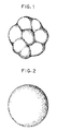
- Fig. 1 is a schematic illustration of an example of the appearance of fine resin particles used in the present invention.
- Fig. 2 is a schematic illustration of the appearance of a fine resin particle having a surface shape sphericity ⁇ of about 1.
- Figs. 3 and 4 are schematic illustration of roller-shaped contact charging devices.
- Fig. 5 is a schematic illustration of a blade-shaped contact charging device.
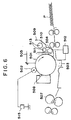
- Fig. 6 is a schematic illustration of an example or the apparatus for carrying out the image forming method of the present invention.
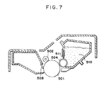
- Fig. 7 is a schematic illustration of an example of the apparatus unit of the present invention.
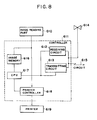
- Fig. 8 is a block diagram to illustrate the facsimile apparatus of the present invention.
- Fig. 9 shows a GPC chromatogram.
- Fig. 10 is a schematic illustration of an apparatus for measuring the quantity of triboelectricity of a powder sample.
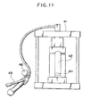
- Fig. 11 is a schematic illustration of a molder for tableting a powder material.
- Fig. 12 illustrates a checker pattern
- the causes of the melt adhesion of toner to the photosensitive member is for one thing the scratches produced when the surface of the photosensitive member is rubbed by a contact charging member to which fine inorganic powder has been adhered.
- the fine resin particles with a surface shape sphericity ⁇ of from 0.90 to 0.50, used in the present invention each have an uneven or irregular surface to a certain extent as diagrammatically shown in Fig. 1, as compared with particles with the shape of true spheres, and hence they have the action of adsorbing to the surface a great number of particles of the fine inorganic powder present in a free state.
- Spherical polymer particles obtained by emulsion polymerization or soap-free polymerization each have, as diagrammatically shown in Fig. 2, very little irregular surface, and hence the surface shape sphericity ⁇ of the polymer particle is more than 0.90. In general, its surface shape sphericity ⁇ is about 1.
- Fine resin particles obtained from a bulk resin by mechanical pulverization or by pulverization using a jet stream have surfaces whose rupture cross-sections assume a great number of minute irregularities and hence the surface shape sphericity ⁇ of the fine resin particle is less than 0.50.
- the surface shape sphericity ⁇ of the fine resin particle is approximately from 0.3 to 0.4.
- the fine resin particles having slipped through a cleaning blade are adsorbed to the contact charging member, and thereafter the fine resin particles present on the surface of the contact charging member adsorb the free, fine inorganic powder slipping through the cleaning blade, so that the surface of the photosensitive member can be prevented from being damaged.
- the fine resin particles slipping through the cleaning blade are in a very large quantity, the free, fine inorganic powder becomes small in quantity and hence the melt adhesion of toner to the photosensitive member can be more effectively prevented, but on the other hand a thick layer of the fine resin particles is formed on the contact charging member and hence this can be one of the causes of faulty charging of the photosensitive member.
- the fine resin particles used in the present invention each have an irregular surface to a certain extent as diagrammatically shown in Fig. 1, and hence they can be appropriately controlled in the quantity of the particles slipping through the cleaning blade, compared with particles with the shape of true spheres, so that the faulty charging of the photosensitive member can be prevented from occurring.
- the surface shape sphericity ⁇ of the fine resin particles is more than 0.90, the faulty charging of the photosensitive member may come to occur when copies are taken on a large number of sheets (e.g., 10,000 sheets or more). If the surface shape sphericity ⁇ is less than 0.50, the fine resin particles may have a great number of irregularities on their surfaces to lend to increase moisture absorption and lower development performance of the developer in an environment of high temperature and high humidity. Moreover, the protruded portions on the surface of fine resin particles tend to be broken off on the occasion of their mixing with toner particles or in the course of development, so that a large number of fragments of the fine resin particles may become present in the developer to tend to adversely affect the development.
- the fine resin particles used in the present invention may preferably have a primary average particle diameter of from 0.03 to 1.0 ⁇ m. It is more preferable to use those of from 0.05 to 0.8 ⁇ m. Particles with a primary average particle diameter larger than 1.0 ⁇ m have so small a specific surface area that they can not be suited for adsorption of the free, fine inorganic powder and can give only a small effect of preventing the melt adhesion of toner to the photosensitive member. On the other hand, those with a primary average particle diameter smaller than 0.03 ⁇ m may make the triboelectricity of the developer excessively high to tend to cause a lowering of density because of charge-up.
- the fine resin particles may have a specific resistance of from 10 6 to 10 13 ⁇ cm, which can be preferably used. Use of those having a water-specific resistance lower than 10 6 ⁇ cm tends to cause a lowering of the charge quantity of the developer, consequently tending to bring about a lowering of image density. Use of fine resin particles having a specific resistance higher than 10 13 ⁇ cm tends to cause a lowering of the fluidity of the developer, and tends to give an image with much fogging.
- the fine resin particles may preferably have a triboelectric charge quantity of not more than +50 ⁇ c/g in the case of positive charging, and not more than 200 ⁇ c/g as the absolute value in the case of negative charging. They may more preferably have a triboelectric charge quantity in the range of from +30 ⁇ c/g to -100 ⁇ c/g. If the triboelectric charge quantity of the fine resin particles is higher than +50 ⁇ c/g, the triboelectricity of the developer tends to become unstable, and fogging tends to occur when copies are taken on a large number of sheets. If the triboelectric charge quantity of the fine resin particles is smaller than -200 ⁇ c/g, the fluidity tends to become poor and density uneveness tends to occur on the image.
- the fine resin particles should be used in an amount of from 0.01 to 1.0 part by weight, and preferably from 0.03 to 0.57 parts by weight based on 100 parts by weight of the toner.
- the fine inorganic powder such as hydrophobic fine silica powder may preferably be used in an amount of from 0.1 part by weight to 3.0 parts by weight based on 100 parts by weight of the toner.
- the fine inorganic powder may preferably be used in a larger amount than the fine resin particles.
- Use of the fine resin particles in an amount more than 1.0 part by weight tends to cause a lowering of image density. On the other hand, use thereof in an amount of less than 0.01 part by weight can be less effective against the melt adhesion of toner to the photosensitive member. Use of the fine resin particles in the same amount as, or in a larger amount than, that of the fine inorganic powder tends to make the fluidity of the developer poor and also tends to cause fogging.
- the BET specific surface area can be actually measured, when, for example, a specific surface area meter AUTOSORB-1, available from Quantachrome Co. is used, by the method as exemplified below.
- the surface area measured assuming the fine resin particles as true spheres can be determined, for example, in the following way: From particles in an electron microscope photograph (x10,000) of the fine resin particles, 100 fine resin particle images are collected at random, and their major axes are measured. A value obtained by averaging the measured major axes is regarded as a diameter (l) measured assuming the fine resin particles as ture spheres. On the basis of the diameter (l), a radius ⁇ (i.e., 1/2 l) is determined and a surface area (4 ⁇ 2 ) of the fine resin particles is further determined. Then a volume (4/3 ⁇ 3 ) of the fine resin particles is further obtained. The weight of the fine resin particles is determined from a density of the fine resin particles and the volume thus obtained. The surface area (m 2 /g) measured assuming the fine resin particles as true spheres is determined from the surface area previously obtained and the weight thus obtained.
- the triboelectric value of the fine resin particles used in the present invention can be measured by the following method: 0.2 g of the fine resin particles having been left for 12 hours or more in an environment of 23.5°C and 60 % RH and 20.0 g of carrier iron powder whose particles are not coated with resin, having a main particle size at 200 to 300 meshes (e,g., EFV200/300, available from Nihon Teppun K.K.) are precisely weighed in the above environment, which are then thoroughly mixed in a wide mouthed bottle with a stopper, made of polyethylene and having a volume of about 50 cc (the bottle is upward and downward shaken in hand about 125 times for 50 seconds).
- a stopper made of polyethylene and having a volume of about 50 cc (the bottle is upward and downward shaken in hand about 125 times for 50 seconds).
- the total weight of the measuring container 32 in this state is weighed and is expressed by W 1 (g).
- a suction device made of an insulating material at least at the part coming into contact with the measuring container 32
- air is sucked from a suction opening 37 and an air-flow control valve 36 is operated to control the pressure indicated by a vacuum indicator 35 to be 250 mmHg. In this state, suction is carried out for 5 minutes to remove the fine resin particles by suction.
- the potential indicated by a potentiometer 39 at this time is expressed by V (volt).
- the numeral 38 denotes a capacitor, whose capacitance is expressed by C ( ⁇ F).
- the total weight of the measuring container after completion of the suction is also weighed and is expressed by W 2 (g).
- the specific resistance (volume specific resistivity) referred to in the present invention can be measured, for example, in the following way: Using an apparatus shown in Fig. 11, the sample is molded into a tablet. First, about 0.3 g of a sample 40 is put in a tablet molding chamber 41. Next, a push bar 42 is inserted to the tablet molding chamber, and the sample is pressed by means of an oil pressure pump 45 at 250 kg/cm 2 for 5 minutes. Thus, a pellet-shaped tablet of about 13 mm in diameter and about 2 to 3 mm in height is molded.
- reference numeral 46 denotes a pressure gauge.
- the tablet thus obtained is optionally coated with a conducting agent on its both sides, and the resistivity under application of a voltage of 1,000 V is measured in an environment of a temperature of 23.5°C and a humidity of 65 % RH, using, for example, 16008A RESISTIVITY CELL, available from Hewlett Pakard Co., or 4329A HIGH RESISTANCE METER, available from Yokogawa Hewlett Pakard Co.
- the fine resin particles can be prepared by emulsion polymerization or spray drying. They may preferably be fine resin particles with a glass transition point of 80°C or above, prepared by subjecting components used in hinder resins for toner, such as styrene, acrylic acid, metylmethacrylate, butyl acrylate and 2-ethylhexyl acrylate, to copolymerization according to emulsion polymerization. Such fine resin particles can have a good effect.
- the fine resin particles may be those cross-linked with a cross-linking agent such as divinylbenzene, and also their surfaces may be treated with a metal, a metal oxide, a pigment, a dye or a surface active agent to make adjustment of specific resistance and triboelectric charge quantity.
- a cross-linking agent such as divinylbenzene
- the fine resin particles used in the present invention may particularly preferably be comprised of a block or random copolymer of a styrene type, containing 51 % by weight or more of styrene monomers.
- styrene type fine resin particles are usually in the triboelectric series approximate to styrene-acrylate resins or polyester resins used in binder resins of developers, so that they can be less mutually electrified with respect to toner particles and their fluidity does not tend to become poor.
- styrene resins are preferred as the binder resin of the toner.
- the developer may come to have strong agglomerating properties and poor fluidity, tending to cause blank areas in images and image density non-uniformity.
- the styrene type fine resin particles have a tendency that the value ⁇ becomes smaller with an increase in the content of styrene monomers.
- the styrene type find resin particles with a surface shape sphericity ⁇ of from 0.90 to 0.50 according to the present invention can be obtained by controlling monomer composition, compositional ratios of monomers and polymerization conditions.
- the fine inorganic powder used in the present invention can give good results when its particles have a specific surface area of from 70 to 300 m 2 /g as measured by the BET method, utilizing to nitrogen adsorption.
- the fine inorganic powder should be used in an amount of from 0.1 part by weight to 3.0 parts by weight, and preferably from 0.2 part by weight to 2.0 parts by weight, based on 100 parts by weight of the toner.
- the fine inorganic powder may preferably be those having been subjected to hydrophobic treatment. They may particularly preferably be negatively chargeable, hydrophobic fine silica powder.
- the fine inorganic powder used in the present invention may have a triboelectric charge quantity of from -100 ⁇ c/g to -300 ⁇ c/g, which can be preferably used.
- Powder with a triboelectric charge quantity less than -100 ⁇ c/g may lower the triboelectric charge quantity of the developer itself, tending to bring about a lowering of humidity characteristics.
- Use of powder with a triboelectric charge quantity more than -300 ⁇ c/g may promote the developer carrying member memory, so that the developer carrying member tends to be affected by the deterioration of the fine inorganic powder, tending to have difficulties in durability.
- Powder finer than 300 m 2 /g in specific surface area may give less effect of its addition to the developer, end powder coarser than 70 m 2 /g may give a larger probability that it is present as a free matter, tending to cause black dots due to locallization of the fine inorganic powder or agglomerated matters.
- the triboelectric value of the fine inorganic powder can be measured by the following method: 0.2 g of the fine inorganic powder having been left overnight in an environment of a temperature of 23.5°C and a humidity 60 % RH and 9.8 g of carrier iron powder whose particles are not coated with resin, having a main particle size at 200 to 300 meshes (e.g., EFV200/300, available from Nihon Teppun K.K.) are precisely weighed in the above environment, which are then thoroughly mixed in a wide-mouthed bottle with a stopper, made of polyethylene and having a volume of about 50 cc (the bottle is upward and downward shaken in hand about 50 times for about 20 seconds).
- a stopper made of polyethylene and having a volume of about 50 cc
- the triboelectric charge quantity of the fine inorganic powder may be measured in the same way as in the measurement of the triboelectric charge quantity of the fine resin particles as previously described.
- dry silica or dry silica called fumed silica, produced by vapor phase oxidation of a silicon halide, and what is called wet silica produced from water glass or the like, both of which can be used.
- dry silica is preferred, which has loss silanol groups present on the surfaces and the insides or the silica fine powder particles and may produce no residues in the manufacture, such as Na 2 O and SO 3 2- .
- the fine inorganic powder includes such a powder.
- the fine inorganic powder may preferably have a particle diameter ranging from 0.001 to 2 ⁇ as the primary average particle diameter. It is particularly preferred to use fine silica powder having a primary average particle diameter ranging from 0.002 to 0.2 ⁇ .
- the fine inorganic powder used in the present invention may preferably be hydrophobic.
- the powder can be made hydrophobic using conventionally known hydrophobic treatments and methods.
- hydrophobic treatments it is preferable to use silicon compounds having organosiloxane units, such as silicone oil or silicone varnish.
- the silicone oil used in the treatment of the fine inorganic powder used in the present invention can be exemplified by a compound represented by the formula: wherein R represents an alkyl group having 1 to 3 carbon atoms; R' represents a silicone oil modifying group such as an alkyl group, a halogen-modified alkyl group, a phenyl group or a modified phenyl group; and R'' represents an alkyl group or alkoxyl group having 1 to 3 carbon atoms.
- the compound may include dimethylsilicone oil, alkyl-modified silicone oil, ⁇ -methylstyrene-modified silicone oil, chlorophenylsilicone oil, fluorine-modified silicone oil. Examples of the silicone oil are by no means limited to these.
- the above silicone oil may preferably be those having a viscosity of from 50 to 1,000 cSt at a temperature of 25°C. Silicone oil with a viscosity less than 50 cSt may be partially evaporated as a result of the application of heat, tending to cause a deterioration of charge characteristics. Those with a viscosity more than 1,000 cSt may become difficult to handle in the treatment. As methods for the silicone oil treatment, any known techniques can be used.
- they include a method in which fine silica powder and silicone oil are mixed using a mixer; a method in which silicone oil is sprayed into fine silica powder by the use of a sprayer, and a method in which silicone oil is dissolved in a solvent and then fine silica powder is mixed in the solution.
- the treatment method are by no means limited to these.
- silicone varnish used for the treatment of the fine silica powder used in the present invention any known materials can be used.
- treated silica As methods for the silicone varnish treatment, the same known techniques as in the silicone oil treatment can be used.
- the treated fine silica powder as described above (hereinafter “treated silica”) can be effective when it is added in an amount of from 0.1 part by weight to 1.6 parts by weight based on 100 parts by weight of the toner. It can provide an excellent stability when added in an amount of from 0.3 part by weight to 1.6 parts by weight based on 100 parts by weight of the toner. Its addition in an amount less than 0.1 part by weight based on 100 parts by weight of the toner may give less effect of its addition, and addition in an amount more than 1.6 parts by weight tends to cause problems in development and fixing, which are thus not preferable.
- Part or the silicon compound having an organosiloxane unit, which has treated the particle surfaces of the fine inorganic powder is transferred onto the electrostatic image bearing member, and is effective for making easier the cleaning of powder such as free polyolefin.
- hydrophobicity the degree to which powder has been made hydrophobic
- a value measured by the following method may be used.
- other method for measurement can also be used while making reference to the method for measurement according to the present invention.
- a 200 ml separatory funnel with a stopper 100 ml of ion-exchanged water and 0.1 g of a sample are put, followed by shaking for 10 minutes using a shaker (a tumbler shaker mixer, T2C type) under conditions of 90 rpm. After the shaking, the mixture is left to stand for 10 minutes. After the inorganic powder layer and the aqueous layer have been separated, the lower layer, the aqueous layer, is collected in a quantity of 20 to 30 ml, which is then put in a 10 mm cell to measure its transmittance using light with a wavelength of 500 nm, on the basis of that of a blank, ion-exchanged water in which no fine silica powder is contained. The value of the transmittance is regarded as the hydrophobicity of the fine inorganic powder.
- the hydrophobic fine inorganic powder may preferably have a hydrophobicity of not less than 60 %, and more preferably not less than 90 %.
- a hydrophobicity less than 60 % makes it difficult to obtain images with a high quality level because of adsorption of water to the fine inorganic powder in an environment of high humidity.
- the developer may preferably contain the fine resin particles having a surface shape sphericity ⁇ of from 0.90 to 0.50 and an average particle diameter of from 0.03 to 1.0 ⁇ m and the hydrophobic fine inorganic powder; said hydrophobic fine inorganic powder being contained in a larger quantity than the fine resin powder.
- the toner according to the present invention should have an average particle diameter of from 3.5 to 20 ⁇ m, preferably from 3.5 to 14 ⁇ m, and more preferably from 4 to 8 ⁇ m, as weight average particle diameter, and from 2.8 to 18 ⁇ m, preferably from 2.8 to 13 ⁇ m, and more preferably from 3 to 7 ⁇ m, as number average particle diameter.
- a toner having a weight average particle diameter (D 4 ) of from 4 to 8 ⁇ m is preferred because of its excellent fine-line reproduction and resolution.
- Particle size distribution of the toner can be measured by various methods. In the present invention, it is measured using a Coulter counter.
- a Coulter counter Type TA-II (manufactured by Coulter Electronics, Inc.) is used as a measuring device.
- An interface manufactured by Nikkaki k.k.
- CX-1 manufactured by Canon Inc.
- an electrolytic solution an aqueous 1 % NaCl solution is prepared using first-grade sodium chloride.
- Measurement is carried out by adding as a dispersant 0.1 ml to 5 ml or a surface active agent, preferably An alkylbenzene sulfonate, to 100 ml to 150 ml of the above aqueous electrolytic solution, and further adding 2 mg to 20 mg (as the number of particles, about 30,000 to about 300,000 particles) of a sample to be measured.
- the electrolytic solution in which the sample has been suspended is subjected to dispersion for about 1 minute to about 3 minutes in an ultrasonic dispersion machine.
- the particle size distribution of particles with a size of from 2 to 40 ⁇ is measured by means or the above Coulter counter Type TA-II, using an aperture of 100 ⁇ as its aperture. Then the value according to the present invention is determined.
- the toner used in the developer of the present invention when it has a negative triboelectricity, may preferably contain as a charge control agent an organic acid metal complex salt such as a salicylic acid metal complex salt, an alkylsalicylic acid metal complex salt, a dialkylsalicylic acid metal complex salt or a naphthoic acid metal complex salt, a dye such as a monoazo dye, and a monoazo dye derivative such as a metal complex salt of a monoazo dye.
- an organic acid metal complex salt such as a salicylic acid metal complex salt, an alkylsalicylic acid metal complex salt, a dialkylsalicylic acid metal complex salt or a naphthoic acid metal complex salt
- a dye such as a monoazo dye
- a monoazo dye derivative such as a metal complex salt of a monoazo dye.
- the negative charge control agent comprising a dye compound may include azo type metal complex salts represented by the following Formula (I).
- M represents a coordination central metal, including Cr, Co, Ni, Mn and Fe having the coordination number of 6
- Ar represents an aryl group, including a phenyl group and a naphthyl group, which may have a substitutent, which substituent may include a nitro group, a halogen atom, a carboxyl group, an anilide group and an alkyl group or alkoxyl group having 1 to 18 carbon atoms
- X, X', Y and Y' each represent -O-, -CO-, -NH- or -NR-, where R represents an alkyl group having 1 to 4 carbon atoms
- a ⁇ represents a hydrogen ion, a sodium ion, a potassium ion, an ammonium ion or an aliphatic ammonium ion.
- a positive charge control agent it is possible to use, for example, a Nigrosine dye and a derivative thereof.
- the charge control agent may preferably be contained in an amount of from 0.1 part by weight to 5 parts by weight, and particularly preferably from 0.2 part by weight to 3 parts by weight based on 100 parts by weight of the binder resin for the toner.
- Use of the charge control agent in an excessively large amount may make poor the fluidity of the toner, tending to cause fogging. On the other hand, use thereof in an excessively small amount may make it difficult to obtain a sufficient charge quantity.
- the developer for developing an electrostatic image may include a developer for developing an electrostatic image, comprising i) a toner containing a charge control agent and having a weight average particle diameter (D 4 ) of from 4 to 8 ⁇ m, ii) styrene type fine organic particles having a smaller average particle diameter than said toner and having a surface shape sphericity ⁇ of from 0.90 to 0.50 and iii) fine inorganic particles having a smaller average particle diameter than said fine organic powder.
- a developer for developing an electrostatic image comprising i) a toner containing a charge control agent and having a weight average particle diameter (D 4 ) of from 4 to 8 ⁇ m, ii) styrene type fine organic particles having a smaller average particle diameter than said toner and having a surface shape sphericity ⁇ of from 0.90 to 0.50 and iii) fine inorganic particles having a smaller average particle diameter than said fine organic powder.
- the binder resin for the toner according to the present invention may include homopolymers of styrene or derivatives thereof such as polystyrene and polyvinyltoluene: styrene copolymers such as a styrene/propylene copolymer, a styrene/vinyltoluene copolymer, a styrene/vinylnaphthalene copolymer, a styrene/methyl acrylate copolymer, a styrene/ethyl acrylate copolymer, a styrene/butyl acrylate copolymer, a styrene/octyl acrylate copolymer, a styrene/dimethylaminoethyl acrylate copolymer, a styrene/methyl methacrylate copolymer, a st
- the toner in the present invention may preferably contain a binder resin containing not less than 15 % of a component with a molecular weight of not more than 5,000 in molecular weight distribution as measured by gel permeation chromatography (GPC).
- GPC gel permeation chromatography
- the content of the component with a molecular weight of not more than 5,000 in the binder resin is a numerical value calculated by determining area proportion of that component in a chromatogram showing molecular weight distribution in the measurement by GPC.
- a chromatogram showing molecular weight distribution in the measurement by GPC as shown in Fig. 9, the area of the whole peak indicating the molecular weight distribution is determined and also the area or the region corresponding to the component with a molecular weight of not more than 5,000 is determined.
- the content of the component with a molecular weight of not more than 5,000 in the binder resin is calculated.
- the component with a molecular weight of not more than 5,000 may more preferably be in an amount of less than 35 %.
- the component with a molecular weight of not more than 5,000 tends to exhibit molecular weight dependence of glass transition point (Tg) and hence the Tg of the toner, measured over a long period of time, is presumed to tend to become a little low. Thus, if the amount or this component is more than 35 %. A thermal behavior not higher than the Tg usually measured may come to be exhibited to tend to cause the melt adhesion or filming.
- Tg glass transition point
- This component can particularly improve the grindability of toners. If, however, its content is more than 35 %, the grindability may become more than is necessary in the manufacture of toners having a weight average particle diameter of from 4 to 8 ⁇ m, resulting in an increase in the formation of ultrafine powder, which makes classification efficiency poor.
- the ultrafine powder having been not completely classified may gradually increase in its content with repetition of the supply of the toner, and may adhere to a toner triboelectricity-providing member such as a developing sleeve because of electrostatic force to impede triboelectric charging of the toner, tending to cause a poor development performance such as a low image density and fogging.
- a toner triboelectricity-providing member such as a developing sleeve because of electrostatic force to impede triboelectric charging of the toner, tending to cause a poor development performance such as a low image density and fogging.
- the molecular weight distribution on the chromatogram obtained by GPC are measured under the following conditions.
- THF tetrahydrofuran
- THF sample solution is injected thereinto to make measurement.
- the molecular weight distribution ascribed to the sample is calculated from the relationship between the logarithmic value and count number of a calibration curve prepared using several kinds of monodisperse polystyrene standard samples.
- the standard polystyrene samples used for the preparation of the calibration curve it is suitable to use, for example, samples with molecular weights of approximately from 10 2 to 10 7 , which are available from Toso Co., Ltd. or Showa Denko K.K., and to use at least about 10 standard polystyrene samples.
- An RI (refractive index) detector is used as a detector. Columns should be used in combination of a plurality of commercially available polystyrene gel columns.
- they may preferably comprise a combination of Shodex GPC KF-801, 802, 803, 804, 805, 806, 807 and 800P, available from Showa Denko K.K.; or a combination of TSKgel G1000H(H XL ), G2000H(H XL ), G3000H(H XL ), G4000H(H XL ), G5000H(H XL ), G6000H(H XL ), G7000H(H XL ) and TSKguard-column, available from Toso Co., Ltd.
- the sample is prepared in the following way: A sample is put in THF, which is left to stand for several hours, followed by thorough shaking so that the sample is well mixed with THF (until the sample become free of coalescence), which is further left to stand for 12 hours or more. Here, the sample is so made as to be left in THF for 24 hours or more. Thereafter, the sample is passed through a sample treating filter (pore size: 0.45 to 0.5 ⁇ m; for example, Maiehoridisk H 25 5, available from Toso Co., Ltd., or Ekikurodisk 25CR, available from German Science Japan Ltd. can be used), and the resulting sample is used as the sample for GPC. Concentration of the sample is so controlled as to give a resin component of from 0.5 to 5 mg/ml.
- the developer of the present invention may preferably comprise i) a toner containing the binder resin containing not less than 15 % of a component with a molecular weight of not more than 5,000 in molecular weight distribution as measured by GPC, ii) styrene type fine organic powder having a smaller average particle diameter than said toner and iii) fine inorganic particles having a smaller average particle diameter than said fine organic particles; the surface shape sphericity ⁇ of said styrene type fine organic powder being in the range of from 0.90 to 0.50.
- the developer of the present invention may preferably be a one-component magnetic developer comprising a magnetic toner containing a magnetic material in the toner particle.
- the magnetic material serves also as a colorant.
- the magnetic material contained in the magnetic toner may include iron oxides such as magnetite, hematite and ferrite; and metals such as iron, cobalt and nickel, or alloys of any of these metals with a metal or metals such as aluminum, cobalt, copper, lead, magnesium, tin, zinc, antimony, beryllium, bismuth, cadmium, calcium, manganese, selenium, titanium, tungsten and/or vanadium, and mixtures of any of these.
- the magnetic material should preferably be a magnetic material having a BET surface specific area or from 1 to 20 m 2 /g, and particularly preferably from 2.5 to 12 m 2 /g, as measured by the nitrogen adsorption method. It may also preferably be a magnetic powder having a Mohs hardness of from 5 to 7. This magnetic powder should be contained in an amount of from 10 to 70 % by weight based on the toner weight.
- any of these magnetic materials may preferably be those having an average particle diameter of from 0.1 to 2 ⁇ m, and more preferably from 0.1 to 0.5 ⁇ m, and should be contained in the toner in an amount of from 20 to 200 parts by weight based on 100 parts by weight of the resin component, and particularly preferably from 40 to 150 parts by weight based on 100 parts by weight of the resin component.
- the magnetic material may preferably be those having a coercive force (Hc) of from 20 to 150 Oe, a saturation magnetization ( ⁇ s) of from 50 to 200 emu/g and a residual magnetization ( ⁇ r) of from 2 to 20 emu/g.
- Hc coercive force
- ⁇ s saturation magnetization
- ⁇ r residual magnetization
- the colorant usable in the toner may include any suitable pigments or dyes.
- the pigments may include, for example, carbon black, aniline black, acetylene black, Naphthol Yellow, Hansa Yellow, Rhodamine Lake, alizarin Lake, red iron oxide, Phthalocyanine Blue and Indanthrene Blue. Any of those may be used in an amount large enough to maintain the optical density of fixed images.
- the pigment may preferably be used in an amount of from 0.1 part by weight to 20 parts by weight, and more preferably from 1 part by weight to 10 parts by weight, based on 100 parts by weight of the resin.
- the dyes may also be used for the same purpose. They may include, for example, azo dyes, anthraquinone dyes, xanthene dyes and methine dyes.
- the dye may preferably be used in an amount of from 0.1 part by weight to 20 parts by weight, and more preferably from 0.3 part by weight to 10 parts by weight, based on 100 parts by weight of the resin.
- the toner used in the present invention may preferably contain a wax in the toner particle.
- the wax may include, for example, polyolefin waxes, solid paraffin wax, micro wax, rice wax, amide waxes, fatty acid waxes, fatty acid metal salt waxes, partially saponified fatty acid ester waxes, silicone wax, higher alcohols, and carnauba wax.
- the wax may preferably be contained in an amount of from 0.5 part by weight to 20 parts by weight, and more preferably from 1 part by weight to 12 parts by weight, based on 100 parts by weight of the binder resin for the toner.
- Wax in an excessively large content may result in an increase in free wax, making it impossible to prevent the problems of faulty cleaning, contamination of fixing rollers, a lowering of developing performance, etc., even in the developer containing the styrene type fine resin particles of the present invention.
- wax in an excessively small content may result in a lowering of fixing performance and anti-offset.
- the wax may preferably have a broad molecular weight distribution. From the viewpoint of improving cleaning performance of OPC photosensitive members, it may preferably be not less than 5, and more preferably from 5 to 10, in weight average molecular weight/number average molecular weight (Mw/Mn).
- polyolefin waxes are particularly preferred. Of these, polypropylene wax and polyethylene wax are preferred. Use of such wax enables achievement of better fixing performance, cleaning performance and developing performance.
- olefin monomers constituting the polyolefin waxes it is possible to use, for example, ethylene, propylene, butene-1, pentene-1, hexene-1, heptene-1, octene-1, nonene-1 and decene-1, or isomers of any of these, having unsaturated bonds at different positions, and also olefin monomers having branched chains comprising an alkyl group, such as 3-methyl-1-butene, 3-methyl-2-pentene and 3-propyl-5-methyl-2-hexene.
- the molecular weight distribution of the wax according to the present invention can be measured, for example, in the following way. Measurment conditions:
- the developer of the present invention may preferably comprise i) a toner containing a wax with a weight average molecular weight/number average molecular weight (Mw/Mn) of not less than 5, ii) styrene type fine organic particles having a smaller average particle diameter than said toner, and iii) fine inorganic particles having a smaller average particle diameter than said styrene type fine organic particles; the surface shape sphericity ⁇ of said styrene type fine organic powder being in the range of from 0.90 to 0.50.
- Mw/Mn weight average molecular weight/number average molecular weight
- a lubricant such as Teflon or zinc stearate or, as a conductivity-providing agent, a metal oxide such as tin oxide may be added so long as the developer is substantially not adversely affected.
- Methods for the preparation of the toner may include a method in which component materials are well kneaded using a heat kneader such as a heat roll, a kneader or an extruder, followed by pulverization and classification to obtain the toner; a method in which other materials are dispersed in a binder resin solution, followed by spray drying to obtain the toner; and a method in which given materials are mixed in monomers that constitute the binder resin, to form an emulsified suspension, followed by polymerization to obtain the toner.
- a heat kneader such as a heat roll, a kneader or an extruder
- the developer of the present invention can be prepared by dry-mixing the toner, the organic fine resin particles and the fine inorganic powder by means of a mixing machine such as Henschel mixer.
- a contact charging process that can be preferably used in the present invention will be specifically described below.
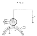
- FIG. 3 schematically illustrates the constitution of an example of the contact charging device or assembly.
- Reference numeral 1 denotes a photosensitive drum which is a chargeable member serving as the electrostatic image bearing member, and is comprised of a conductive substrate comprising a drum substrate 1a made of aluminum, on the external surface of which an organic photoconductor (OPC) 1b serving as a photosensitive layer is formed.
- OPC organic photoconductor
- the photosensitive drum is rotated at a given speed in the direction of an arrow
- the photosensitive drum 1 is 30 mm in outer diameter.
- Reference numeral 2 denotes a charging roller which is a charging member brought into contact with the photosensitive drum 1 at a given pressure, and is comprised of a metal mandrel 2a, a conductive rubber layer 2b provided thereon, and further provided on its external surface a surface layer 2c, a release film.
- the conductive rubber layer may preferably have a thickness of from 0.5 to 10 mm, and preferably from 1 to 5 mm.
- the surface layer in this example comprises a release film. It is preferred to provide this release film so that the developer and image forming method according to the present invention may match each other.
- a release film with an excessively large resistivity may give no electrostatic charges on the photosensitive drum 1 and on the other hand a release film with an excessively small resistivity may cause an excessively large voltage applied to the photosensitive drum 1 to tend to damage the drum or produce pinholes, and hence the release film should have an appropriate resistivity.
- the release film should have a volume resistivity of from 10 9 to 10 14 ⁇ cm.
- the release film may preferably have a thickness of not more than 30 ⁇ m. The lower limit of the thickness of the film may be smaller so long as no peel or turn-up may occur, and can be considered to be about 5 ⁇ m.
- the release film should have a thickness of from 10 to 30 ⁇ m.
- the charging roller 2 has an outer diameter of 12 mm.
- the conductive rubber layer 2b having a thickness of 3.5 mm, is composed of an ethylene-propylene-diene terpolymer (EPDM), and the surface layer 2c is formed of a nylon resin in a thickness of 10 ⁇ m.
- the charging roller 2 is made to have a hardness of 54.5° (ASKER-C).
- Letter symbol E denotes a power source that applies a voltage to the charging roller 2. It supplies a given voltage to the mandrel 2a (diameter: 5 mm) of the charging roller 2.
- the letter symbol E indicates a DC voltage. It may preferably be a direct current overlaid with an AC voltage as shown in Fig. 4.
- Fig. 5 schematically illustrates the constitution of another example of the contact charging member according to the present invention.
- the members common to those in the device shown in Figs. 3 and 4 have the same reference number, and repetitive description thereon is omitted.
- a contact charging member 3 is blade-shaped, which is brought into contact with the photosensitive drum 1 in the normal direction under a given pressure.
- This blade 3 in comprised of a holding metal member 3a to which a voltage is applied, a conductive rubber 3b supported by the member 3a, and a surface layer 3c serving as the release film, provided at the part coming into contact with the photosensitive drum 1.
- the surface layer 3c is formed of nylon in a thickness or 10 ⁇ m. According to this example, difficulties such as sticking of the blade to the photosensitive drum do not occur, and the same operation and effect as in the previous examples can be achieved.
- roller-shaped or blade-shaped member is used as the charging member.
- the present invention can also be carried out using a member with a different shape.
- the charging member is constituted of a conductive rubber layer and a release film. Its constitution is by no means limited to it.
- a high-resistance layer e.g., a hydrin rubber layer with less environmental variations
- PVDF polyvinylidene fluoride
- PVDC polyvinylidene chloride
- amorphous silicon, selenium, ZnO, etc. can also be used. In the case when amorphous silicon is used in the photosensitive member, smeared images may seriously occur, compared with the case when other material is used, if the softening agent in the conductive rubber layer adheres to the photosensitive member even in a small quantity. Hence, it can be more effective to provide such an insulative coating on the outer side of the conductive rubber layer.
- the present invention is particularly effective for an image forming apparatus comprising an electrostatic image bearing member (a photosensitive drum) whose surface is formed of an organic compound. This is because, in the case when an organic compound forms a surface layer, the binder resin containing the toner tends to adhere to the surface layer and hence the melt adhesion of toner tends to occur at the contact point particularly when the same materials are used.
- Surface materials for the the electrostatic image bearing member according to the present invention may include silicone resin, vinylidene chloride, ethylene-vinyl chloride, styrene-acrylonitrile, styrene methyl methacrylate, styrene, polyethylene terephthalate, and polycarbonate.
- the materials are by no means limited to these, and other monomers or their copolymers or blends with any of the exemplified resins can also be used.
- the present invention is particularly effective for an image forming apparatus comprising an electrostatic image bearing member with a diameter of 50 mm or less. This is because, in the case of drums with a small diameter, pressure tends to be locallized at the contact part because of a large curvature even under the same linear pressure.
- the same phenomenon is considered to occur in belt type photosensitive members, and the present invention is particularly effective for an image forming apparatus wherein the curvature radius at the transfer portion is 25 mm or less.
- the developer for developing an electrostatic image according to the present invention can be preferably used particularly in a heat roller fixing system.
- a heat roller fixing device is normally comprised of a heat roller, a pressure roller provided opposingly thereto, and a heat source built in the heating roller.
- a cleaning roller is optionally provided opposingly to the heating roller.
- a transfer medium with a toner image having been transferred thereto is passed through between the heating roller and the pressure roller while keeping the temperature of the heating roller to a given temperature by means of the heat source, whereby the toner image is brought into direct contact with the heating roller so that the toner image can be fixed by heat and pressure to the transfer medium.
- the heating roller may preferably be made of a fluorine type material or a silicone type material, which can remarkably improve the durability of the heating roller because or the cooperative action of the material and the developer of the present invention.
- the surface of a photosensitive member 501 serving as the electrostatic image bearing member is negatively charged by the operation of a contact charging assembly 502, the contact charging means previously described, having a voltage applying means 616, and a digital latent image is formed by image scanning through exposure 505 using a laser beam.
- the lament image thus formed is reversely developed using a negatively chargeable one-component magnetic developer 510 held in a developing assembly 509 equipped with a developing sleeve 504 in which a magnetic blade 511 and a magnet are provided.
- an AC bias, a pulse bias and/or a DC bias is/are applied between a conductive substrate of the photosensitive drum 501 and the developing sleeve 504 through a bias applying means 512.
- a transfer paper P is fed and delivered to a transfer zone, where the transfer paper P is electrostatically charged from its back surface (the surface opposite to the photosensitive drum) through a transfer means 503, so that the developed image (toner image) on the surface of the photosensitive drum is electrostatically transferred to the transfer paper P.
- the transfer paper P separated from the photosensitive drum 501 is subjected to fixing using a heat-pressure roller fixing unit (thermal platen) 507 so that the toner image on the transfer paper P can be fixed.
- the one-component magnetic toner remaining on the photosensitive drum 501 after the transfer step is removed by the operation of a cleaning assembly 508 having a cleaning blade (or a cleaning roller). After the cleaning, the residual charges on the photosensitive drum 501 is eliminated by erase exposure 506 if necessary, and thus the procedure again starting from the charging step using the contact charging assembly 502 is repeated.
- the erase exposure may be omitted when an AC bias is applied to the contact charging assembly 502.
- the electrostatic image bearing member (the photosensitive drum) comprises a photosensitive layer and a conductive substrate as previously described, and is rotated in the direction of an arrow.
- a non magnetic cylinder which is the developer carrying member, is rotated so as to move in the same direction as the direction in which the electrostatic image bearing member is rotated.
- a multi-polar permanent magnet (magnet roll) serving as a magnetic field generating means is provided in an unrotatable state.
- the one-component insulating magnetic toner 510 held in the developing assembly 509 is coated on the surface of the non-magnetic cylindrical sleeve 504, and, for example, minus triboelectric charges are imparted to the developer because of the friction between the surface of the sleeve 504 and the the developer.
- a doctor blade 511 made of iron is disposed opposingly to one of the magnetic pole positions of the multi-polar permanent magnet, in proximity (with a space of from 50 ⁇ m to 500 ⁇ m) to the surface of the cylinder.
- the thickness of a toner layer can be controlled to be small (from 30 ⁇ m to 300 ⁇ m) and uniform so that a toner layer smaller in thickness than the gap between the electrostatic image bearing member 501 and developer carrying member 504 in the developing zone can be formed in a non-contact state.
- the rotational speed of this developer carrying member 504 is regulated so that the peripheral speed of the sleeve can be substantially equal or close to the speed of the peripheral speed of the electrostatic image bearing member.
- a permanent magnet may be used in place of iron to form an opposing magnetic pole.
- the AC bias or pulse bias may be applied through the bias means 512, across the developer carrying member 504 and the surface of the electrostatic image bearing member 501.
- This AC bias may have a frequency of from 200 to 4,000 Hz, and a Vpp of from 500 to 3,000 V.
- the toner particles When the toner particles are moved in the developing zone, the toner particles are moved to the side of an electrostatic image by the electrostatic force of the electrostatic image bearing member surface and the action of the AC bias or pulse bias.
- an elastic blade formed of an elastic material such as silicone rubber may be used so that the layer thickness of the developer layer can be controlled by pressure and the developer can be thereby coated on the developer carrying member.
- the cleaning step may be simultaneously carried out in the charging step, developing step or transfer step.
- the electrophotographic apparatus may be constituted of a combination of plural components integrally joined as one apparatus unit from among the constituents such as the above electrostatic image bearing member, developing means and cleaning means so that the unit can be freely mounted on or detached from the body of the apparatus.
- at least one of the contact charging means, developing means and cleaning means may be integrally supported together with the electrostatic image bearing member to form one unit that can be freely mounted on or detached from the body of the apparatus, and the unit can be freely mounted or detached using a guide means such as a rail provided in the body of the apparatus.
- optical image exposing light 505 serves as exposing light used for the printing of received data.
- Fig. 8 illustrates an example thereof in the form of a block diagram.
- a controller 611 controls an image reading part 610 and a printer 619. The whole of the controller 611 is controlled by CPU 617. Image data outputted from the image reading part is sent to the other facsimile station through a transmitting circuit 613. Data received from the other station is sent to a printer 619 through a receiving circuit 612. Given image date are stored in an image memory 616. A printer controller 618 controls the printer 619.
- the numeral 614 denotes a telephone.
- An image received from a circuit 615 (image information from a remote terminal connected through the circuit) is demodulated in the receiving circuit 612, and then successively stored in an image memory 616 after the image information is decoded by the CPU 617. Then, when images for at least one page have been stored in the memory 616, the image recording for that page is carried out.
- the CPU 617 reads out the image information for one page from the memory 616 and sends the coded image information for one page to the printer controller 618.
- the printer controller 618 having received the image information for one page from the CPU 617, controls the printer 619 so that the image information for one page is recorded.
- the CPU 617 receives image information for next page in the course of the recording by the printer 619.
- Styrene/n-butyl methacrylate/divinylbenzene copolymer (copolymerization ratio:70:29:1; Mw: 280,000) 100 parts Fine magnetic powder (BET value: 7.5 m 2 /g) 100 parts Negative charge control agent (exemplary complex (I)-3) 0.5 part
- the above materials were melt-kneaded using a twin-screw extruder heated to 140°C. After cooled, the kneaded product was crushed using a hammer mill to give coarse particles, which were then finely pulverized using a jet mill. The resulting finely pulverized product was subjected to air classification to give a classified magnetic powder (magnetic toner 1) with a weight average particle diameter (D 4 ) of 6.8 ⁇ m (number average particle diameter:5.2 ⁇ m) (Tg: 60°C). The magnetic toner obtained had negative triboelectric chargeability and also had electrical insulating properties.
- a classified magnetic powder (magnetic toner 2) having the same average particle diameter as that in Preparation Example 1 was obtained in the same manner as in Preparation Example 1 except that as the charge control agent the exemplary complex (I)-3 was replaced with exemplary complex (I)-2.
- a classified magnetic powder (magnetic toner 3) having the same average particle diameter as that in Preparation Example 1 was obtained in the same manner as in Preparation Example 1 except that as the charge control agent the exemplary complex (I)-3 was replaced with exemplary complex (I) 6.
- a classified magnetic powder (magnetic toner 4) having the same average particle diameter as that in Preparation Example 1 was obtained in the same manner as in Preparation Example 1 except that no negative charge control agent was used.
- a classified magnetic powder (magnetic toner 5) with a weight average particle diameter of 12.5 ⁇ m, having trip same average particle diameter as that in Preparation Example 1 was obtained in the same manner as in Preparation Example 1 except that the fine magnetic powder was used in an amount of 60 parts.
- the photosensitive member used was on OPC photosensitive member comprising a drum substrate on the external surface of which a photosensitive layer comprised of a charge generation layer and a charge transport layer (comprising a charge transporting compound dispersed in polycarbonate resin), and the photosensitive member had a surface with abrasion characteristics of 2.5 x 10 -2 cm 3 as abrasion wear measured using a Taber's abrasion resistance tester.
- the charging roller 2 has a diameter of 12 mm
- the mandrel has a diameter of 5 mm
- the conductive rubber layer 2b has a thickness of about 3.5 mm
- the release film formed of methoxymethylated nylon has a thickness of 20 ⁇ m.
- the roller was brought into pressure contact with the OPC photosensitive member at a total pressure of 1.2 kg (linear pressure: 55 g/cm).
- the toner layer on the sleeve was made to have a thickness of 130 ⁇ m, and the gap where the sleeve and the OPC photosensitive member become closest was set to be 300 ⁇ m.
- Image reproduction tests were carried out while applying a DC bias (-500 V) and an AC bias (1,800 Hz, 1,600 Vpp) to the developing sleeve.
- Tables 1 and 2 show physical properties of the fine resin particles (A) and those of the fine silica powder (B), respectively.
- Table 3 shows the composition of each developer and the results of evaluation.
- the blade type charging assembly as shown in Fig. 4 was used in Example 5, and the roller type as shown in Fig. 4 was used in Examples 1 to 4 and Comparative Examples 1 to 5.
- Charge non-uniformity due to the contamination of the charging member was evaluated by observing lateral line images of about 100 ⁇ in line intervals and about 100 ⁇ in line width.
- Fine resin particles A Fine resin particles Surface shape sphericity ⁇ Number av.
- the above material were melt kneaded using a twin-screw extruder heated to 140°C. After cooled, the kneaded product was crushed using a hammer mill to give coarse particles, which were then finely pulverized using a jet mill. The resulting finely pulverized product was subjected to air classification to give a classified magnetic powder (magnetic toner 6) with a weight average particle diameter (D 4 ) of 7.8 ⁇ m (number average particle diameter:6.1 ⁇ m) (Tg: 60°C).
- a classified magnetic powder (magnetic toner 9) having the same average particle diameter as that in Preparation Example 6 was obtained in the same manner as in Preparation Example 6 except that no low-molecular weight polypropylene was used.
- Copolymer I 100 parts Fine magnetic powder (BET value: 7.5 m 2 /g) 80 parts Negative charge control agent: 3,5-di-tert-butylsalicylic acid chromium complex 2 parts
- the above materials were melt-kneaded using a twin-screw extruder heated to 140°C. After cooled, the kneaded product was crushed using a hammer mill to give coarse particles, which were then finely pulverized using a jet mill. The resulting finely pulverized product was subjected to air classification to give a classified magnetic powder (magnetic toner 10) with a weight average particle diameter (D 4 ) of 7.8 ⁇ m (number average particle diameter:6.1 ⁇ m) (Tg: 60°C).
- Classified magnetic powders (magnetic toners 11 to 13) having the same average particle diameter as that in Preparation Example 10 were obtained in the same manner as in Preparation Example 10 except that the copolymer I was replaced with copolymer II to IV, respectively.
- Table 5 shows the composition of each copolymer, Tg, and weight fraction of the region with a molecular weight of not more than 5,000 in the measurement by GPC after the toners have been formed.
- Charge non-uniformity due to the contamination of the charging member was examined on lateral line images of about 100 ⁇ in intervals and about 100 ⁇ in line width (in an environment of low temperature and low humidity).
- Melt adhesion of toner to the surface of the photosensitive member was evaluated on the basis of the number of white dots in solid black images. (Since it tends to occur in an environment of high temperature and high humidity, tests were carried out in a environment of high temperature and high humidity.)
- Fixing performance was evaluated in the following way: In an environment of normal temperature and normal humidity (23.5°C, 60 % RH), a power source was switched on after the evaluation machine became accustomed to that environment. Immediately after wait-up, lateral line patterns of 200 ⁇ in line width (width: 200 ⁇ ; intervals: 200 ⁇ m) were printed (on A4 paper set lengthwise). A printed image on the first sheet was used for the evaluation of fixing performance. For the evaluation of fixing performance, the image was rubbed to and fro five times with Silbon paper under a load of 100 g, and image come-off was examined on the basis of the average of image density fall rates (%).
- Styrene/n-butyl acrylate copolymer (copolymerization ratio: 8:2; Mw: 270,000) 100 parts Fine magnetic powder (BET value: 8.5 m 2 /g) 60 parts Negative charge control agent (a monoazo dye chromium complex) 0.6 part Low-molecular weight polypropylene (Mw: 6,000) 3 parts
- the above materials were melt-kneaded using a twin-screw extruder heated to 140°C. After cooled, the kneaded product was crushed using a hammer mill to give coarse particles, which were then finely pulverized using a jet mill. The resulting finely pulverized product was subjected to air classification to give a classified magnetic powder (magnetic toner 14) with a volume average particle diameter of 12 ⁇ m (Tg: 60°C).
- Styrene/2-ethylhexyl acrylate/maleic acid n-butyl half ester copolymer (copolymerization ratio: 7:2:1; Mw: 200,000) 100 parts Fine magnetic powder (BET value: 7.5 m 2 /g) 60 parts Negative charge control agent (a salicylic acid chromium complex) 2 parts Low-molecular weight polypropylene (Mw: 6,000) 3 parts
- Example 14 The above materials were treated in the same manner as in Example 14 to give a classified magnetic powder (magnetic toner 15) (Tg: 55°C).
- these respective one-component magnetic developers thus prepared were each loaded in the image forming apparatus as shown in Fig. 6 (a modified machine of LBP-8II, manufactured by Canon Inc.) having a contact charging assembly. While applying a DC voltage and an AC voltage (500 Hz, 2,000 Vpp), practical copy tests to form toner images continuously on A4-size paper at a printing speed of 16 sheets/min according to the reversal development system were carried out in an environment of normal temperature and normal humidity (25°C, 60 % RH), and print-out images were evaluated. At the same time, the state of the surfaces of the charging member (roller type) and OPC photosensitive drum was examined.
- Table 7 shows physical properties of the fine resin particles (A).
- Table 8 shows the composition of each developer and the results of evaluation.
- the developer of the present invention can give a toner image that is free from toner contamination or fogging and has a high quality.
Claims (62)
- Elektrophotographischer Entwickler zur Entwicklung elektrostatischer Bilder, umfassend einen Toner, feine Harzpartikel mit einer Oberflächensphärizität ψ von 0,90 bis 0,50 und feine anorganische Partikel.
- Entwickler nach Anspruch 1, wobei der mittlere Partikeldurchmesser der feinen Harzpartikel kleiner als der mittlere Partikeldurchmesser des besagten Toners und größer als der Partikeldurchmesser des besagten anorganischen Pulvers ist.
- Entwickler nach Anspruch 1, wobei die besagten feinen Harzpartikel einen mittleren Primärpartikeldurchmesser von 0,03 bis 1,0 µm haben.
- Entwickler nach Anspruch 1, wobei die besagten feinen Harzpartikel einen mittleren Primärpartikeldurchmesser von 0,05 bis 0,8 µm haben.
- Entwickler nach Anspruch 1, wobei die besagten feinen Harzpartikel eine triboelektrische Ladungsmenge von -200 µC/g bis +50 µC/g haben.
- Entwickler nach Anspruch 1, wobei die besagten feinen Harzpartikel eine triboelektrische Ladungsmenge von -100 µC/g bis +30 µC/g haben.
- Entwickler nach Anspruch 1, wobei die besagten feinen Harzpartikel einen spezifischen Widerstand von 106 Ω*cm bis 1013 Ω*cm haben.
- Entwickler nach Anspruch 1, wobei die besagten feinen Harzpartikel ein Styrolharz umfassen.
- Entwickler nach Anspruch 1, wobei die besagten feinen Harzpartikel nicht weniger als 51 Gew.% Styrol-Monomereinheiten enthalten.
- Entwickler nach Anspruch 1, wobei die besagten feinen Harzpartikel eine Glasübergangs-Temperatur von 80°C oder höher haben.
- Entwickler nach Anspruch 1, wobei besagter Toner einen gewichtsmittleren Partikeldurchmesser von 3,5 bis 20 µm, besagte feine Harzpartikel einen mittleren Primärpartikel-Durchmesser von 0,03 bis 1,0 µm und besagtes feines anorganisches Pulver einen mittleren Primärpartikel-Durchmesser von 0,002 µm bis 0,2 µm haben, wobei der mittlere Primärpartikel-Durchmesser des besagten anorganischen Pulvers kleiner ist als der mittlere Primärpartikel-Durchmesser der besagten feinen Harzpartikel.
- Entwickler nach Anspruch 11, wobei besagter Toner einen gewichtsmittleren Partikeldurchmesser von 3,5 µm bis 14 µm hat.
- Entwickler nach Anspruch 11, wobei besagter Toner einen gewichtsmittleren Partikeldurchmesser von 4 µm bis 8 µm hat.
- Entwickler nach Anspruch 13, wobei besagter Toner Tonerpartikel umfaßt, die ein Ladungseinstellmittel enthalten.
- Entwickler nach Anspruch 1, wobei besagter Toner Tonerpartikel umfaßt, die ein negatives Ladungseinstellmittel enthalten, dargestellt durch folgende Formel (I)worin M Cr, Co, Ni oder Fe mit der Koordinationszahl 6 bedeutet; Ar einen Arylrest bedeutet, der einen Substituenten tragen kann; X, X', Y und Y' gleich oder verschieden sein können und jeweils -O-, -CO-, -NH- oder -NR- bedeuten, wobei R ein Alkylrest mit 1 bis 4 Kohlenstoffatomen ist; und A⊕ ein Wasserstoffion, ein Natriumion, ein Kaliumion, ein Ammoniumion oder ein aliphatisches Ammoniumion bedeutet.

- Entwickler nach Anspruch 1, wobei besagter Toner Tonerpartikel umfaßt, die ein Wachs mit einem Verhältnis (Mw/Mn) des gewichtsmittleren Molekulargewichts (Mw) zum zahlenmittleren Molekulargewicht (Mn) von nicht weniger als 5 enthalten.
- Entwickler nach Anspruch 1, wobei besagter Toner Tonerpartikel mit einem Binderharz umfaßt, das nicht weniger als 15 % einer Komponente mit einem Molekulargewicht von nicht über 5000 gemäß GPC-Chromatogramm enthält.
- Entwickler nach Anspruch 1, wobei besagter Toner Tonerpartikel mit einem Binderharz umfaßt, das 15 % bis 35 % einer Komponente mit einem Molekulargewicht von nicht über 5000 gemäß GPC-Chromatogramm enthält.
- Entwickler nach Anspruch 1, wobei besagter Toner magnetische Tonerpartikel umfaßt.
- Entwickler nach Anspruch 1, wobei besagter Toner nichtleitende magnetische Tonerpartikel mit einer negativtriboelektrischen Aufladbarkeit umfaßt.
- Entwickler nach Anspruch 18, wobei besagter Toner Tonerpartikel mit einem Binderharz umfaßt, das ein Styrolpolymer, ein Styrolcopolymer oder eine Mischung davon umfaßt.
- Verfahren zur Erzeugung elektrostatischer Bilder durch einen elektrophotographischen Prozeß, umfassend folgende Schritte:In-Kontakt-bringen eines Ladeteils, an das eine äußere spannung angelegt wurde, mit einem Elektrostatikbildträger, um eine elektrostatische Aufladung zu bewirken;Erzeugen eines elektrostatischen Bildes auf dem geladenen Bildträger;Entwickeln des elektrostatischen Bildes, das auf dem Elektrostatikbildträger erzeugt worden ist, unter Verwendung eines Entwicklers, der einen Toner, feine Harzpartikel mit einer Oberflächensphärizität ψ von 0,90 bis 0,50 und feine anorganische Partikel umfaßt; undÜbertragen des Tonerbilds, das auf besagtem Elektrostatikbildträger erzeugt worden ist, auf ein Übertragungsmedium, um ein übertragenes Bild zu erzeugen.
- Bilderzeugungsverfahren nach Anspruch 22, wobei besagter Elektrostatikbildträger ein lichtempfindliches Teil mit einem organischen Photoleiter enthält und durch ein Ladeteil negativ aufgeladen wird; auf besagtem Elektrostatikbildträger ein negativ geladenes elektrostatisches Bild erzeugt wird; und besagtes elektrostatische Bild durch den Toner mit negativer triboelektrischer Ladung umkehrentwickelt wird.
- Bilderzeugungsverfahren nach Anspruch 22, wobei eine Gleichspannung an besagtes Ladeteil angelegt wird.
- Bilderzeugungsverfahren nach Anspruch 22, wobei eine Wechelspannung an besagtes Ladeteil angelegt wird.
- Bilderzeugungsverfahren nach Anspruch 22, wobei eine Gleichspannung, überlagert mit einer Wechselspannung, an besagtes Ladeteil angelegt wird.
- Bilderzeugungsverfahren nach Anspruch 22, wobei besagter Elektrostatikbildträger nach dem Übertragungsschitt mit einem Abstreifmesser gereinigt wird.
- Bilderzeugungsverfahren nach Anspruch 27, wobei ein Teil der im Entwickler enthaltenen feinen Harzpartikel nicht durch das Abstreifmesser abgestreift, sondern auf das Ladeteil übertragen wird, so daß besagte feine Harzpartikel an der Oberfläche des besagten Ladeteils haften.
- Bilderzeugungsverfahren nach Anspruch 22, wobei besagtes Ladeteil mit besagtem Elektrostatikbildträger unter einem Druck von 5 g/cm bis 500 g/cm in Kontakt gebracht und eine Gleichspannung von -200 V bis -900 V und eine Wechselspannung von 0,5 kV bis 5 kV (Spitzenspannung) an besagtes Ladeteil angelegt wird.
- Bilderzeugungsverfahren nach Anspruch 29, wobei besagte Wechselspannung eine Wechselfrequenz von 50 Hz bis 3000 Hz hat.
- Bilderzeugungsverfahren nach Anspruch 22, wobei besagtes Ladeteil walzenförmig ist, einen abweisenden Film als Oberflächenschicht hat und den Elektrostatikbildträger während des Rotierens elektrostatisch auflädt.
- Bilderzeugungsverfahren nach Anspruch 22, wobei das elektrostatische Bild mit dem Entwickler nach einem der Ansprüche 2 bis 21 entwickelt wird.
- Elektrophotographischer Apparat, umfassend:einen Elektrostatikbildträger;ein Kontaktladeteil, an das eine äußere Spannung angelegt wird, die besagten Elektrostatikbildträger elektrostatisch auflädt, während es mit diesem in Kontakt gebracht wird;eine ein Elektrostatikbild erzeugende Anordnung zur Erzeugung eines elektrostatischen Bildes auf dem geladenen Elektrostatikbildträger;eine Entwicklungsvorrichtung zur Entwicklung des so erzeugten elektrostatischen Bildes; wobei besagte Entwicklungsvorrichtung ein den Entwickler auftragendes Teil und einen Entwicklerbehälter, der den elektrophotographischen Entwickler enthält, umfaßt; und wobei besagter Entwickler einen Toner, feine Harzpartikel mit einer Oberflächensphärizität ψ von 0,90 bis 0,50 und feine anorganische Partikel umfaßt; undein Übertragungsmittel zur Übertragung des erzeugten Tonerbildes von besagtem Elektrostatikbildträger auf ein Übertragungsmedium.
- Elektrophotographischer Apparat nach Anspruch 33, wobei besagter Elektrostatikbildträger eine lichtempfindliche Schicht mit einem organischen Photoleiter aufweist.
- Elektrophotographischer Apparat nach Anspruch 33, wobei besagtes Kontaktladeteil mit einer Spannungsquelle zur Versorgung mit einer Gleichspannung verbunden ist.
- Elektrophotographischer Apparat nach Anspruch 33, wobei besagtes Kontaktladeteil mit einer Spannungsquelle zur Versorgung mit einer Wechselspannung verbunden ist.
- Elektrophotographischer Apparat nach Anspruch 33, wobei besagtes Kontaktladeteil mit Spannungsquellen zur Versorgung mit einer Gleichspannung, die von einer Wechselspannung überlagert ist, verbunden ist.
- Elektrophotographischer Apparat nach Anspruch 33, wobei besagtes Kontaktladeteil walzenförmig ist.
- Elektrophotographischer Apparat nach Anspruch 33, wobei besagtes Kontaktladeteil messerförmig ist.
- Elektrophotographischer Apparat nach Anspruch 38, wobei besagtes Kontaktladeteil einen abweisenden Film als Oberflächenschicht hat.
- Elektrophotographischer Apparat nach Anspruch 33, wobei an besagtem Elektrostatikbildträger eine Reinigungsvorrichtung zur Beseitigung von verbliebenem Toner nach der Übertragung vorgesehen ist.
- Elektrophotographischer Apparat nach Anspruch 41, wobei besagte Reinigungsvorrichtung mit einem Abstreifmesser ausgestattet ist.
- Elektrophotographischer Apparat nach Anspruch 33, wobei besagter Entwicklungsbehälter den Entwickler nach einem der Ansprüche 2 bis 21 enthält.
- Geräteeinheit, umfassend:einen Elektrostatikbildträger,ein Kontaktladeteil, an das eine äußere Spannung angelegt wird, die besagten Elektrostatikbildträger elektrostatisch auflädt, während es mit diesem in Kontakt gebracht wird; undeine Entwicklungsvorrichtung zur Entwicklung eines so erzeugten elektrostatischen Bildes; wobei besagte Entwicklungsvorrichtung ein den Entwickler auftragendes Teil und einen Entwicklerbehälter, der den elektrophotographischen Entwickler enthält, umfaßt; und wobei besagter Entwickler einen Toner, feine Harzpartikel mit einer Oberflächensphärizität ψ von 0,90 bis 0,50, und feine anorganische Partikel umfaßt; und wobeibesagtes Kontaktladeteil und besagte Entwicklungsvorrichtung mit besagtem Elektrostatikbildträger zu einer Einheit zusammengefaßt sind und besagte Einheit im Gehäuse des elektrophotographischen Apparats abnehmbar angebracht ist.
- Geräteeinheit nach Anspruch 44, wobei besagter Elektrostatikbildträger eine lichtempfindliche Schicht mit einem organischen Photoleiter aufweist.
- Geräteeinheit nach Anspruch 44, wobei besagtes Kontaktladeteil walzenförmig ist.
- Geräteeinheit nach Anspruch 44, wobei besagtes Kontaktladeteil messerförmig ist.
- Geräteeinheit nach Anspruch 46, wobei besagtes Kontaktladeteil einen abweisenden Film als Oberflächenschicht hat.
- Geräteeinheit nach Anspruch 44, wobei besagter Elektrostatikbildträger mit einer Reinigungsvorrichtung zur Reinigung seiner Oberfläche von Tonerrückständen versehen ist.
- Geräteeinheit nach Anspruch 49, wobei besagte Reinigungsvorrichtung ein Abstreifmesser enthält.
- Geräteeinheit nach Anspruch 44, wobei besagter Entwicklerbehälter den Entwickler nach einem der Ansprüche 2 bis 21 enthält.
- Faksimile-Apparatur aus einem elektrophotographischen Apparat und einer Empfangsvorrichtung zu Empfang von Bildinformationen von einer entfernten Station, wobei der besagte elektrophotographische Apparat folgendes umfaßt:einen Elektrostatikbildträger;ein Kontaktladeteil, an das eine äußere Spannung angelegt wird und das den besagten Elektrostatikbildträger elektrostatisch auflädt, während es mit diesem in Kontakt gebracht wird;eine ein elektrostatisches Bild erzeugende Anordnung zur Erzeugung eines elektrostatischen Bildes auf dem aufgeladenen Elektrostatikbildträger;eine Entwicklungsvorrichtung zur Entwicklung des so erzeugten elektrostatischen Bildes, wobei besagte Entwicklungsvorrichtung ein den Entwickler auftragendes Teil und einen Entwicklungsbehälter umfaßt, der den elektrophotographischen Entwickler enthält; wobei besagter Entwickler einen Toner, feine Harzpartikel mit einer Oberflächensphärizität ψ von 0,90 bis 0,50 sowie feine anorganische Partikel umfaßt; undein Übertragungsmittel zum Übertragen des Tonerbilds, das auf besagtem Elektrostatikbildträger erzeugt wurde, auf ein Übertragungsmedium.
- Faksimile-Apparatur nach Anspruch 52, wobei besagter Elektrostatikbildträger eine lichtempfindliche Schicht mit einem organischen Photoleiter aufweist.
- Faksimile-Apparatur nach Anspruch 52, wobei besagtes Kontaktladeteil mit einer Spannungsquelle zum Anlegen einer Gleichspannung verbunden ist.
- Faksimile-Apparatur nach Anspruch 52, wobei besagtes Kontaktladeteil mit einer Spannungsquelle zum Anlegen einer Wechselspannung verbunden ist.
- Faksimile-Apparatur nach Anspruch 52, wobei besagtes Kontaktladeteil mit Spannungsquellen zum Anlegen einer Gleichspannung, die von einer Wechselspannung überlagert ist, verbunden ist.
- Faksimile-Apparatur nach Anspruch 52, wobei besagtes Kontaktladeteil walzenförmig ist.
- Faksimile-Apparatur nach Anspruch 52, wobei besagtes Kontaktladeteil messerförmig ist.
- Faksimile-Apparatur nach Anspruch 57, wobei besagtes Kontaktladeteil einen abweisenden Film als Oberflächenschicht aufweist.
- Faksimile-Apparatur nach Anspruch 52, wobei besagter Elektrostatikbildträger mit einer Reinigungsvorrichtung zur Reinigung seiner Oberfläche von Tonerrückständen versehen ist.
- Faksimile-Apparatur nach Anspruch 60, wobei besagte Reinigungsvorrichtung mit einem Abstreifmesser ausgerüstet ist.
- Faksimile-Apparatur nach Anspruch 52, wobei besagter Entwicklerbehälter den Entwickler nach einem der Ansprüche 2 bis 21 enthält.
Applications Claiming Priority (8)
| Application Number | Priority Date | Filing Date | Title |
|---|---|---|---|
| JP287158/90 | 1990-10-26 | ||
| JP28715890 | 1990-10-26 | ||
| JP36166/91 | 1991-03-01 | ||
| JP36165/91 | 1991-03-01 | ||
| JP3618091 | 1991-03-01 | ||
| JP36180/91 | 1991-03-01 | ||
| JP3616691 | 1991-03-01 | ||
| JP3616591 | 1991-03-01 |
Publications (2)
| Publication Number | Publication Date |
|---|---|
| EP0482665A1 EP0482665A1 (de) | 1992-04-29 |
| EP0482665B1 true EP0482665B1 (de) | 1998-03-04 |
Family
ID=27460216
Family Applications (1)
| Application Number | Title | Priority Date | Filing Date |
|---|---|---|---|
| EP91118252A Expired - Lifetime EP0482665B1 (de) | 1990-10-26 | 1991-10-25 | Entwickler zur Entwicklung elektrostatischer Bilder, Bilderzeugungsverfahren, elektrographischer Apparat, Geräteeinheit und Faksimile-Apparatur |
Country Status (4)
| Country | Link |
|---|---|
| US (2) | US5270143A (de) |
| EP (1) | EP0482665B1 (de) |
| DE (1) | DE69128998T2 (de) |
| SG (1) | SG78355A1 (de) |
Families Citing this family (29)
| Publication number | Priority date | Publication date | Assignee | Title |
|---|---|---|---|---|
| DE69326735T2 (de) * | 1992-08-25 | 2000-04-27 | Canon Kk | Toner zur Entwicklung elektrostatischer Bilder und Bilderzeugungsverfahren |
| JP2985594B2 (ja) * | 1992-12-03 | 1999-12-06 | セイコーエプソン株式会社 | 画像形成方法 |
| US5464722A (en) * | 1993-01-11 | 1995-11-07 | Canon Kabushiki Kaisha | Production of toner for developing electrostatic images |
| US5534982A (en) * | 1993-03-03 | 1996-07-09 | Canon Kabushiki Kaisha | Developing apparatus |
| US5439772A (en) * | 1993-03-26 | 1995-08-08 | Fuji Xerox Co., Ltd. | Magnetic toner and process for producing the same |
| JPH0792876A (ja) * | 1993-04-28 | 1995-04-07 | Canon Inc | 画像形成装置 |
| US5397670A (en) * | 1993-07-13 | 1995-03-14 | Industrial Technology Research Institute | Single-component non-magnetic toner developer for electrophotographic processes |
| US6245473B1 (en) * | 1993-07-30 | 2001-06-12 | Canon Kabushiki Kaisha | Electrophotographic apparatus with DC contact charging and photosensitive layer with polycarbonate resin in charge generation layer |
| DE69523362T2 (de) * | 1994-04-15 | 2002-07-11 | Canon Kk | Bilderzeugungsverfahren und Prozesskassette |
| US6010811A (en) * | 1994-10-05 | 2000-01-04 | Canon Kabushiki Kaisha | Two-component type developer, developing method and image forming method |
| EP0715230B1 (de) * | 1994-11-28 | 2001-10-10 | Canon Kabushiki Kaisha | Bilderzeugungsverfahren |
| DE69612892T2 (de) * | 1995-02-10 | 2001-10-25 | Canon Kk | Bildherstellungsverfahren, Bildherstellungsgerät und Tonerelemente |
| DE69611744T2 (de) * | 1995-06-27 | 2001-08-02 | Canon Kk | Toner für die Entwicklung elektrostatischer Bilder, Bildherstellungsverfahren, Entwicklungsapparateinheit, und Prozesskassette |
| US5695902A (en) * | 1995-11-20 | 1997-12-09 | Canon Kabushiki Kaisha | Toner for developing electrostatic image, image forming method and process-cartridge |
| EP0791861B1 (de) * | 1996-02-20 | 2003-05-07 | Canon Kabushiki Kaisha | Bildherstellungsverfahren |
| US6033817A (en) * | 1996-07-31 | 2000-03-07 | Canon Kabushiki Kaisha | Toner for developing electrostatic image and image forming method |
| TWI259202B (en) * | 2000-06-01 | 2006-08-01 | Asahi Kasei Corp | Cleaning method and cleaning apparatus |
| EP1408901A1 (de) * | 2001-07-23 | 2004-04-21 | FOS Holding S.A. | Vorrichtung zum abtrennen der epithelschicht von der oberfläche der hornhaut eines auges |
| US7156859B2 (en) | 2001-07-23 | 2007-01-02 | Fos Holding S.A. | Device for separating the epithelium layer from the surface of the cornea of an eye |
| US20070265650A1 (en) * | 2001-07-23 | 2007-11-15 | Ioannis Pallikaris | Device for separating the epithelial layer from the surface of the cornea of an eye |
| US7247662B2 (en) * | 2001-10-07 | 2007-07-24 | Nippon Shokubai Co., Ltd. | Cement dispersant, its production process, and cement composition using the cement dispersant |
| US6946505B2 (en) * | 2001-10-17 | 2005-09-20 | Nippon Shokubai Co., Ltd. | Cement dispersant, its production process, and cement composition using the cement dispersant |
| CA2508689A1 (en) * | 2002-12-10 | 2004-06-24 | Sightrate B.V. | Disposable separator for separating the epithelium layer from the cornea of an eye |
| US20040260321A1 (en) * | 2002-12-19 | 2004-12-23 | Ming-Kok Tai | Apparatus and method for separating the epithelium layer from the cornea of an eye without corneal pre-applanation |
| JP5114958B2 (ja) * | 2007-02-02 | 2013-01-09 | 富士ゼロックス株式会社 | プロセスカートリッジおよび画像形成装置 |
| CN102046702B (zh) * | 2008-06-02 | 2014-02-12 | 佳能株式会社 | 树脂细颗粒水性分散体、树脂细颗粒水性分散体的制造方法和调色剂颗粒的制造方法 |
| CN102449555B (zh) | 2009-05-28 | 2014-08-13 | 佳能株式会社 | 调色剂的生产方法和调色剂 |
| US10151990B2 (en) | 2016-11-25 | 2018-12-11 | Canon Kabushiki Kaisha | Toner |
| JP7327993B2 (ja) | 2019-05-13 | 2023-08-16 | キヤノン株式会社 | トナー及びトナーの製造方法 |
Family Cites Families (32)
| Publication number | Priority date | Publication date | Assignee | Title |
|---|---|---|---|---|
| BE789988A (fr) * | 1971-10-12 | 1973-04-12 | Xerox Corp | Composition de revelateur et procede pour son emploi |
| BE789987A (fr) * | 1971-10-12 | 1973-04-12 | Xerox Corp | Composition de revelateur et procede pour son emploi |
| JPS496523A (de) * | 1972-04-10 | 1974-01-21 | ||
| JPS5013661A (de) * | 1973-06-12 | 1975-02-13 | ||
| JPS5752574B2 (de) * | 1973-07-10 | 1982-11-08 | ||
| JPS60186854A (ja) * | 1984-03-06 | 1985-09-24 | Fuji Xerox Co Ltd | 電子写真トナー |
| US4943505A (en) * | 1984-03-06 | 1990-07-24 | Fuji Xerox Co., Ltd. | Developer and toner composition produced by emulsion polymerization |
| US4702986A (en) * | 1984-08-30 | 1987-10-27 | Canon Kabushiki Kaisha | Electrophotographic method uses toner of polyalkylene and non-magnetic inorganic fine powder |
| JPS61273556A (ja) * | 1985-05-29 | 1986-12-03 | Nippon Paint Co Ltd | 静電写真用乾式トナ− |
| US4973541A (en) * | 1986-10-03 | 1990-11-27 | Minolta Camera Kabushiki Kaisha | Electrostatic latent image developer comprising capsule toner of irregular shape, wrinkled surface |
| JPS63208062A (ja) * | 1987-02-25 | 1988-08-29 | Toshiba Corp | 現像方法 |
| DE3851968T2 (de) * | 1987-02-26 | 1995-03-30 | Canon Kk | Bilderzeugungsgerät. |
| US4891294A (en) * | 1987-07-09 | 1990-01-02 | Hitachi Metals, Ltd. | Electrostatic development toner |
| US4885222A (en) * | 1987-07-21 | 1989-12-05 | Konica Corporation | Method for developing electrostatic latent image in an oscillating electric field |
| JPH0760273B2 (ja) * | 1987-10-26 | 1995-06-28 | キヤノン株式会社 | 磁性現像剤 |
| JPH01113762A (ja) * | 1987-10-28 | 1989-05-02 | Konica Corp | 静電像現像用トナー |
| JPH0727280B2 (ja) * | 1987-11-06 | 1995-03-29 | コニカ株式会社 | 静電像現像剤 |
| US4967231A (en) * | 1987-12-29 | 1990-10-30 | Kabushiki Kaisha Toshiba | Apparatus for forming an electrophotographic latent image |
| CA1326154C (en) * | 1988-02-29 | 1994-01-18 | Koichi Tomiyama | Magnetic toner for developing electrostatic images |
| US5041351A (en) * | 1988-03-30 | 1991-08-20 | Canon Kabushiki Kaisha | One component developer for developing electrostatic image and image forming method |
| DE3828876A1 (de) * | 1988-08-25 | 1990-03-08 | Henkel Kgaa | Verwendung von copolymeren von langkettigen alkylacrylaten mit n-haltigen olefinen als verlaufmittel fuer pulverlacke |
| JPH087454B2 (ja) * | 1988-10-21 | 1996-01-29 | 三田工業株式会社 | トナー組成物及びその製造方法 |
| JP2810389B2 (ja) * | 1988-11-17 | 1998-10-15 | キヤノン株式会社 | 正帯電性現像剤 |
| JP2702194B2 (ja) * | 1988-12-13 | 1998-01-21 | コニカ株式会社 | 静電像現像用キャリヤおよび製造方法 |
| JPH02256065A (ja) * | 1988-12-19 | 1990-10-16 | Konica Corp | 磁性トナー |
| JPH0682227B2 (ja) * | 1989-04-26 | 1994-10-19 | キヤノン株式会社 | 磁性現像剤 |
| US4937633A (en) * | 1989-07-21 | 1990-06-26 | Xerox Corporation | Cleaning blade defect sensing arrangement |
| US5139914A (en) * | 1989-07-28 | 1992-08-18 | Canon Kabushiki Kaisha | Developer for developing electrostatic images and image forming apparatus |
| US5182604A (en) * | 1990-03-17 | 1993-01-26 | Canon Kabushiki Kaisha | Transfer roller with voltage polarity control |
| KR970005219B1 (ko) * | 1990-09-14 | 1997-04-14 | 캐논 가부시끼가이샤 | 화상기록장치 |
| JPH04268583A (ja) * | 1991-02-22 | 1992-09-24 | Canon Inc | 帯電装置 |
| JP3134007B2 (ja) * | 1991-11-13 | 2001-02-13 | 株式会社リコー | 画像形成装置 |
-
1991
- 1991-10-25 EP EP91118252A patent/EP0482665B1/de not_active Expired - Lifetime
- 1991-10-25 DE DE69128998T patent/DE69128998T2/de not_active Expired - Lifetime
- 1991-10-25 SG SG1999002752A patent/SG78355A1/en unknown
- 1991-10-28 US US07/783,185 patent/US5270143A/en not_active Expired - Lifetime
-
1993
- 1993-09-10 US US08/118,720 patent/US5319424A/en not_active Expired - Lifetime
Also Published As
| Publication number | Publication date |
|---|---|
| US5270143A (en) | 1993-12-14 |
| EP0482665A1 (de) | 1992-04-29 |
| DE69128998D1 (de) | 1998-04-09 |
| DE69128998T2 (de) | 1998-07-30 |
| SG78355A1 (en) | 2001-02-20 |
| US5319424A (en) | 1994-06-07 |
Similar Documents
| Publication | Publication Date | Title |
|---|---|---|
| EP0482665B1 (de) | Entwickler zur Entwicklung elektrostatischer Bilder, Bilderzeugungsverfahren, elektrographischer Apparat, Geräteeinheit und Faksimile-Apparatur | |
| US5139914A (en) | Developer for developing electrostatic images and image forming apparatus | |
| EP0791861B1 (de) | Bildherstellungsverfahren | |
| EP0784237B1 (de) | Toner für die Herstellung elektrostatischer Bilder, Geräteeinheit und Bildherstellungsverfahren | |
| US4499168A (en) | Fixing method | |
| EP1128225B1 (de) | Magnetischer Toner und Bildherstellungsverfahren unter Verwendung desselben | |
| EP0947887B1 (de) | Toner für die Entwicklung elektrostatischer Bilder und Bildherstellungsverfahren | |
| EP0335676B1 (de) | Entwickler zur Entwicklung elektrostatischer Bilder und Bildherstellungsverfahren | |
| EP0410482A2 (de) | Bilderzeugungsgerät | |
| US7625685B2 (en) | Magnetic mono-component toner for developing electrostatic latent image and image forming method | |
| US20070147886A1 (en) | Toner, method for forming image using the toner, and process cartridge | |
| US5486443A (en) | Magnetic toner compositions with silica, strontium titanate and polyvinylidene fluoride | |
| EP0466149A1 (de) | Toner, Entwickler und Bilderzeugungsverfahren | |
| JPH0786703B2 (ja) | トナー | |
| US5210617A (en) | Developer for developing electrostatic images and image forming apparatus | |
| JP3093371B2 (ja) | 静電荷像現像用現像剤、画像形成方法、電子写真装置、装置ユニット及びファクシミリ装置 | |
| JP4644106B2 (ja) | 磁性トナーとそれを用いた画像形成方法 | |
| JP3230011B2 (ja) | 画像形成方法及びそれに用いられる画像形成用現像剤 | |
| JP3720631B2 (ja) | 乾式トナー、乾式トナーの製造方法及び画像形成方法 | |
| JP3213756B2 (ja) | 現像剤及びこれを用いた画像形成方法 | |
| JP2007206530A (ja) | 磁性トナーとそれを用いる画像形成方法 | |
| JP2000162823A (ja) | 画像形成方法及び画像形成用現像剤 | |
| JP3397736B2 (ja) | 画像形成方法及び画像形成用現像剤 | |
| JP3311251B2 (ja) | 画像形成方法 | |
| US7016632B2 (en) | Electrophotographic toner and development process using chemically prepared toner |
Legal Events
| Date | Code | Title | Description |
|---|---|---|---|
| PUAI | Public reference made under article 153(3) epc to a published international application that has entered the european phase |
Free format text: ORIGINAL CODE: 0009012 |
|
| AK | Designated contracting states |
Kind code of ref document: A1 Designated state(s): DE FR GB IT |
|
| 17P | Request for examination filed |
Effective date: 19920911 |
|
| 17Q | First examination report despatched |
Effective date: 19960105 |
|
| GRAG | Despatch of communication of intention to grant |
Free format text: ORIGINAL CODE: EPIDOS AGRA |
|
| GRAG | Despatch of communication of intention to grant |
Free format text: ORIGINAL CODE: EPIDOS AGRA |
|
| GRAH | Despatch of communication of intention to grant a patent |
Free format text: ORIGINAL CODE: EPIDOS IGRA |
|
| GRAH | Despatch of communication of intention to grant a patent |
Free format text: ORIGINAL CODE: EPIDOS IGRA |
|
| GRAA | (expected) grant |
Free format text: ORIGINAL CODE: 0009210 |
|
| AK | Designated contracting states |
Kind code of ref document: B1 Designated state(s): DE FR GB IT |
|
| ITF | It: translation for a ep patent filed |
Owner name: SOCIETA' ITALIANA BREVETTI S.P.A. |
|
| REF | Corresponds to: |
Ref document number: 69128998 Country of ref document: DE Date of ref document: 19980409 |
|
| ET | Fr: translation filed | ||
| PLBE | No opposition filed within time limit |
Free format text: ORIGINAL CODE: 0009261 |
|
| STAA | Information on the status of an ep patent application or granted ep patent |
Free format text: STATUS: NO OPPOSITION FILED WITHIN TIME LIMIT |
|
| 26N | No opposition filed | ||
| REG | Reference to a national code |
Ref country code: GB Ref legal event code: IF02 |
|
| PGFP | Annual fee paid to national office [announced via postgrant information from national office to epo] |
Ref country code: IT Payment date: 20081020 Year of fee payment: 18 |
|
| PGFP | Annual fee paid to national office [announced via postgrant information from national office to epo] |
Ref country code: FR Payment date: 20081024 Year of fee payment: 18 |
|
| PGFP | Annual fee paid to national office [announced via postgrant information from national office to epo] |
Ref country code: DE Payment date: 20091031 Year of fee payment: 19 |
|
| PGFP | Annual fee paid to national office [announced via postgrant information from national office to epo] |
Ref country code: GB Payment date: 20091028 Year of fee payment: 19 |
|
| REG | Reference to a national code |
Ref country code: FR Ref legal event code: ST Effective date: 20100630 |
|
| PG25 | Lapsed in a contracting state [announced via postgrant information from national office to epo] |
Ref country code: FR Free format text: LAPSE BECAUSE OF NON-PAYMENT OF DUE FEES Effective date: 20091102 |
|
| PG25 | Lapsed in a contracting state [announced via postgrant information from national office to epo] |
Ref country code: IT Free format text: LAPSE BECAUSE OF NON-PAYMENT OF DUE FEES Effective date: 20091025 |
|
| GBPC | Gb: european patent ceased through non-payment of renewal fee |
Effective date: 20101025 |
|
| PG25 | Lapsed in a contracting state [announced via postgrant information from national office to epo] |
Ref country code: GB Free format text: LAPSE BECAUSE OF NON-PAYMENT OF DUE FEES Effective date: 20101025 |
|
| REG | Reference to a national code |
Ref country code: DE Ref legal event code: R119 Ref document number: 69128998 Country of ref document: DE Effective date: 20110502 |
|
| PG25 | Lapsed in a contracting state [announced via postgrant information from national office to epo] |
Ref country code: DE Free format text: LAPSE BECAUSE OF NON-PAYMENT OF DUE FEES Effective date: 20110502 |