EP0565565B1 - Elektromechanischer drehflügelantrieb für schwenkflügel von türen oder dergleichen - Google Patents
Elektromechanischer drehflügelantrieb für schwenkflügel von türen oder dergleichen Download PDFInfo
- Publication number
- EP0565565B1 EP0565565B1 EP92901798A EP92901798A EP0565565B1 EP 0565565 B1 EP0565565 B1 EP 0565565B1 EP 92901798 A EP92901798 A EP 92901798A EP 92901798 A EP92901798 A EP 92901798A EP 0565565 B1 EP0565565 B1 EP 0565565B1
- Authority
- EP
- European Patent Office
- Prior art keywords
- drive
- rotary leaf
- electric motor
- rotary
- leaf drive
- Prior art date
- Legal status (The legal status is an assumption and is not a legal conclusion. Google has not performed a legal analysis and makes no representation as to the accuracy of the status listed.)
- Expired - Lifetime
Links
- 230000005540 biological transmission Effects 0.000 claims abstract description 13
- 230000000694 effects Effects 0.000 claims abstract description 4
- 230000002093 peripheral effect Effects 0.000 claims description 4
- 238000013016 damping Methods 0.000 abstract 1
- 238000000034 method Methods 0.000 description 11
- 230000008569 process Effects 0.000 description 11
- 230000004888 barrier function Effects 0.000 description 4
- 230000008859 change Effects 0.000 description 4
- 230000008878 coupling Effects 0.000 description 2
- 238000010168 coupling process Methods 0.000 description 2
- 238000005859 coupling reaction Methods 0.000 description 2
- 239000000463 material Substances 0.000 description 2
- 238000004873 anchoring Methods 0.000 description 1
- 238000010586 diagram Methods 0.000 description 1
- 230000002349 favourable effect Effects 0.000 description 1
- 230000007246 mechanism Effects 0.000 description 1
- 238000005457 optimization Methods 0.000 description 1
- 230000036316 preload Effects 0.000 description 1
- 239000000725 suspension Substances 0.000 description 1
Images


Classifications
-
- E—FIXED CONSTRUCTIONS
- E05—LOCKS; KEYS; WINDOW OR DOOR FITTINGS; SAFES
- E05F—DEVICES FOR MOVING WINGS INTO OPEN OR CLOSED POSITION; CHECKS FOR WINGS; WING FITTINGS NOT OTHERWISE PROVIDED FOR, CONCERNED WITH THE FUNCTIONING OF THE WING
- E05F1/00—Closers or openers for wings, not otherwise provided for in this subclass
- E05F1/08—Closers or openers for wings, not otherwise provided for in this subclass spring-actuated, e.g. for horizontally sliding wings
- E05F1/10—Closers or openers for wings, not otherwise provided for in this subclass spring-actuated, e.g. for horizontally sliding wings for swinging wings, e.g. counterbalance
- E05F1/1041—Closers or openers for wings, not otherwise provided for in this subclass spring-actuated, e.g. for horizontally sliding wings for swinging wings, e.g. counterbalance with a coil spring perpendicular to the pivot axis
- E05F1/105—Closers or openers for wings, not otherwise provided for in this subclass spring-actuated, e.g. for horizontally sliding wings for swinging wings, e.g. counterbalance with a coil spring perpendicular to the pivot axis with a compression spring
-
- E—FIXED CONSTRUCTIONS
- E05—LOCKS; KEYS; WINDOW OR DOOR FITTINGS; SAFES
- E05F—DEVICES FOR MOVING WINGS INTO OPEN OR CLOSED POSITION; CHECKS FOR WINGS; WING FITTINGS NOT OTHERWISE PROVIDED FOR, CONCERNED WITH THE FUNCTIONING OF THE WING
- E05F15/00—Power-operated mechanisms for wings
- E05F15/60—Power-operated mechanisms for wings using electrical actuators
- E05F15/603—Power-operated mechanisms for wings using electrical actuators using rotary electromotors
- E05F15/611—Power-operated mechanisms for wings using electrical actuators using rotary electromotors for swinging wings
-
- E—FIXED CONSTRUCTIONS
- E05—LOCKS; KEYS; WINDOW OR DOOR FITTINGS; SAFES
- E05F—DEVICES FOR MOVING WINGS INTO OPEN OR CLOSED POSITION; CHECKS FOR WINGS; WING FITTINGS NOT OTHERWISE PROVIDED FOR, CONCERNED WITH THE FUNCTIONING OF THE WING
- E05F15/00—Power-operated mechanisms for wings
- E05F15/70—Power-operated mechanisms for wings with automatic actuation
- E05F15/72—Power-operated mechanisms for wings with automatic actuation responsive to emergency conditions, e.g. fire
-
- E—FIXED CONSTRUCTIONS
- E05—LOCKS; KEYS; WINDOW OR DOOR FITTINGS; SAFES
- E05F—DEVICES FOR MOVING WINGS INTO OPEN OR CLOSED POSITION; CHECKS FOR WINGS; WING FITTINGS NOT OTHERWISE PROVIDED FOR, CONCERNED WITH THE FUNCTIONING OF THE WING
- E05F1/00—Closers or openers for wings, not otherwise provided for in this subclass
- E05F1/08—Closers or openers for wings, not otherwise provided for in this subclass spring-actuated, e.g. for horizontally sliding wings
- E05F1/10—Closers or openers for wings, not otherwise provided for in this subclass spring-actuated, e.g. for horizontally sliding wings for swinging wings, e.g. counterbalance
- E05F1/1041—Closers or openers for wings, not otherwise provided for in this subclass spring-actuated, e.g. for horizontally sliding wings for swinging wings, e.g. counterbalance with a coil spring perpendicular to the pivot axis
-
- E—FIXED CONSTRUCTIONS
- E05—LOCKS; KEYS; WINDOW OR DOOR FITTINGS; SAFES
- E05F—DEVICES FOR MOVING WINGS INTO OPEN OR CLOSED POSITION; CHECKS FOR WINGS; WING FITTINGS NOT OTHERWISE PROVIDED FOR, CONCERNED WITH THE FUNCTIONING OF THE WING
- E05F15/00—Power-operated mechanisms for wings
- E05F15/60—Power-operated mechanisms for wings using electrical actuators
- E05F15/603—Power-operated mechanisms for wings using electrical actuators using rotary electromotors
- E05F15/611—Power-operated mechanisms for wings using electrical actuators using rotary electromotors for swinging wings
- E05F15/63—Power-operated mechanisms for wings using electrical actuators using rotary electromotors for swinging wings operated by swinging arms
-
- E—FIXED CONSTRUCTIONS
- E05—LOCKS; KEYS; WINDOW OR DOOR FITTINGS; SAFES
- E05Y—INDEXING SCHEME ASSOCIATED WITH SUBCLASSES E05D AND E05F, RELATING TO CONSTRUCTION ELEMENTS, ELECTRIC CONTROL, POWER SUPPLY, POWER SIGNAL OR TRANSMISSION, USER INTERFACES, MOUNTING OR COUPLING, DETAILS, ACCESSORIES, AUXILIARY OPERATIONS NOT OTHERWISE PROVIDED FOR, APPLICATION THEREOF
- E05Y2201/00—Constructional elements; Accessories therefor
- E05Y2201/40—Motors; Magnets; Springs; Weights; Accessories therefor
- E05Y2201/404—Function thereof
- E05Y2201/41—Function thereof for closing
-
- E—FIXED CONSTRUCTIONS
- E05—LOCKS; KEYS; WINDOW OR DOOR FITTINGS; SAFES
- E05Y—INDEXING SCHEME ASSOCIATED WITH SUBCLASSES E05D AND E05F, RELATING TO CONSTRUCTION ELEMENTS, ELECTRIC CONTROL, POWER SUPPLY, POWER SIGNAL OR TRANSMISSION, USER INTERFACES, MOUNTING OR COUPLING, DETAILS, ACCESSORIES, AUXILIARY OPERATIONS NOT OTHERWISE PROVIDED FOR, APPLICATION THEREOF
- E05Y2201/00—Constructional elements; Accessories therefor
- E05Y2201/40—Motors; Magnets; Springs; Weights; Accessories therefor
- E05Y2201/47—Springs
- E05Y2201/474—Compression springs
-
- E—FIXED CONSTRUCTIONS
- E05—LOCKS; KEYS; WINDOW OR DOOR FITTINGS; SAFES
- E05Y—INDEXING SCHEME ASSOCIATED WITH SUBCLASSES E05D AND E05F, RELATING TO CONSTRUCTION ELEMENTS, ELECTRIC CONTROL, POWER SUPPLY, POWER SIGNAL OR TRANSMISSION, USER INTERFACES, MOUNTING OR COUPLING, DETAILS, ACCESSORIES, AUXILIARY OPERATIONS NOT OTHERWISE PROVIDED FOR, APPLICATION THEREOF
- E05Y2400/00—Electronic control; Electrical power; Power supply; Power or signal transmission; User interfaces
- E05Y2400/10—Electronic control
- E05Y2400/30—Electronic control of motors
- E05Y2400/302—Electronic control of motors during electric motor braking
-
- E—FIXED CONSTRUCTIONS
- E05—LOCKS; KEYS; WINDOW OR DOOR FITTINGS; SAFES
- E05Y—INDEXING SCHEME ASSOCIATED WITH SUBCLASSES E05D AND E05F, RELATING TO CONSTRUCTION ELEMENTS, ELECTRIC CONTROL, POWER SUPPLY, POWER SIGNAL OR TRANSMISSION, USER INTERFACES, MOUNTING OR COUPLING, DETAILS, ACCESSORIES, AUXILIARY OPERATIONS NOT OTHERWISE PROVIDED FOR, APPLICATION THEREOF
- E05Y2800/00—Details, accessories and auxiliary operations not otherwise provided for
- E05Y2800/72—Sets of mutually exchangeable elements, e.g. modular
-
- E—FIXED CONSTRUCTIONS
- E05—LOCKS; KEYS; WINDOW OR DOOR FITTINGS; SAFES
- E05Y—INDEXING SCHEME ASSOCIATED WITH SUBCLASSES E05D AND E05F, RELATING TO CONSTRUCTION ELEMENTS, ELECTRIC CONTROL, POWER SUPPLY, POWER SIGNAL OR TRANSMISSION, USER INTERFACES, MOUNTING OR COUPLING, DETAILS, ACCESSORIES, AUXILIARY OPERATIONS NOT OTHERWISE PROVIDED FOR, APPLICATION THEREOF
- E05Y2900/00—Application of doors, windows, wings or fittings thereof
- E05Y2900/10—Application of doors, windows, wings or fittings thereof for buildings or parts thereof
- E05Y2900/13—Type of wing
- E05Y2900/132—Doors
-
- Y—GENERAL TAGGING OF NEW TECHNOLOGICAL DEVELOPMENTS; GENERAL TAGGING OF CROSS-SECTIONAL TECHNOLOGIES SPANNING OVER SEVERAL SECTIONS OF THE IPC; TECHNICAL SUBJECTS COVERED BY FORMER USPC CROSS-REFERENCE ART COLLECTIONS [XRACs] AND DIGESTS
- Y10—TECHNICAL SUBJECTS COVERED BY FORMER USPC
- Y10T—TECHNICAL SUBJECTS COVERED BY FORMER US CLASSIFICATION
- Y10T74/00—Machine element or mechanism
- Y10T74/18—Mechanical movements
- Y10T74/18568—Reciprocating or oscillating to or from alternating rotary
- Y10T74/18784—Reciprocating or oscillating to or from alternating rotary including bevel gears
Definitions
- the invention relates to an electromechanical rotary leaf drive for pivoting leaves of doors or the like according to the preamble of claim 1.
- An electromechanical drive for pivoting wings of doors or the like has become known, for example, from DE 32 02 930 C2 and comprises an electric motor with a planetary gear arranged in the axial direction of the electric motor axis and firmly connected to the electric motor housing. This is followed by a bevel gear transmission with two opposite free ends of an output shaft.
- the entire structural unit can be used to control a left or right door leaf without further polarity reversal measures.
- the entire arrangement in the housing is formed symmetrically to a central longitudinal plane, the shaft of the electric motor or the longitudinal axis of the planetary gear, which is identical to it, passing through the axis of the output shaft approximately in the middle thereof.
- a return spring unit should preferably be provided in the form of a spiral spring as a further safety measure, which is always seated at the end of the output shaft opposite the linkage required for opening and closing the wing and is supported on the output shaft itself and on the housing.
- two cam disks are provided, via which the electric voltage for the electric motor can be acted upon by a voltage which counteracts the respective direction of movement.
- the main aim of this is to brake the door before reaching the open or closed extreme position. Otherwise, it is only provided that the electric motor to accelerate the wing from one end position (closed, open position) with a high voltage corresponding to the polarity and when swinging the wing into the other end position with a lower voltage.
- the known electromechanical drive has the disadvantage that the spiral spring provided would have to be dimensioned sufficiently strong to be able to carry out the closing movement in a reasonable time.
- the door is almost suddenly closed at high speed, which is not only surprising and completely unfamiliar, but can also be dangerous.
- it is particularly disadvantageous that the closing movement of the door itself is carried out with a strongly changing force during the closing process. This means that the closing kinematics are very different compared to conventional known hydraulic door closers, which are known to be able to close a door largely evenly.
- GB-A-2,206,926 also discloses a rotary vane drive which has a large-sized coil spring which is preferably arranged eccentrically to a rotor / stator arrangement. One end of the coil spring is supported fixed to the housing, whereas the opposite end of the coil spring is connected to the output shaft of the drive unit coupled to the swing door. The door is opened against the force of this coil spring.
- the rotary vane drive is provided with a rotor, a stator and an energy store, the electric motor optionally serving and working as a generator or electric motor as required. From the description, as in particular from FIG. 1 of this prior publication, it can be seen that the torsional moment shown in FIG. 1 and acting on the door is more than 6 times stronger when the maximum opening position of the door is reached than at the beginning of the opening path of the door.
- the drive axis of the electric motor is also aligned in the longitudinal direction of the housing.
- the gear ratio from the clutch output shaft to the shaft shaft is comparatively complex using a ball screw and a rack and pinion drive.
- a return spring device is installed in the housing in the axial direction lying to the side next to the drive transmission members including the rack and pinion drive and the other gearwheels, and is offset in the axial direction from the electric motor. The return spring is comparatively small.
- the generator When the door is closed, the generator is short-circuited to generate a magnetic counterforce to achieve a braking effect in order to influence the closing speed of the door.
- this embodiment also means that when a swing door is opened, the opening forces required change greatly over the entire opening area, i.e. increase strongly.
- the present invention achieves remarkably simple technical progress in an incredibly simple manner. It can be described as quite surprising that a closing kinematics comparable to the conventional closing process can be achieved by the present invention even in the event of a power failure.
- a helical spring is provided for this purpose, which can be of correspondingly large dimensions and, in a preferred embodiment, is arranged around the electric drive motor and the planetary gear connected to the end face with the same central axis.
- the spiral spring surrounds the electric motor with the gear unit which adjoins at the end, preferably in the form of a planetary gear.
- the electric motor is short-circuited in the event of a power failure, as a result of which a generator effect is generated.
- Both measures ensure, on the one hand, that the characteristic curve of the spring device remains practically unchanged during the closing process, that is, it is not subject to the major differences as in the prior art, and that, in addition, by connecting the short-circuited electric motor acting as a generator, for example, a door leaf when closing without current is damped in such a way that the closing movement is carried out similarly to a hydraulic door closer.
- the coil spring is preferably dimensioned so large, i.e. it has such a large diameter and so many turns that the increase in spring torque when opening the door, i.e. during the entire maximum adjustment path, does not exceed 50%, preferably even less than 40%, 30%, 25% or even only 20 % or 10%.
- the helical spring is preferably supported on a driver seated on the output shaft of the planetary gear and on the rear side on a support disk fixed to the housing.
- the support disk fixed to the housing can be preset by suitable measures in order to be able to set or change the preload force of the helical spring.
- a four-quadrant control is used for the electric motor. That is, both in the opening and in the closing direction, the electric motor can be preset or controlled differently with regard to the desired torque and the speed.
- a position transmitter is preferably provided on the rear side of the electromotive drive, which, in a preferred embodiment, can consist not only of one but above all of two light barriers sitting next to one another.
- a position transmitter is preferably provided on the rear side of the electromotive drive, which, in a preferred embodiment, can consist not only of one but above all of two light barriers sitting next to one another.
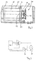
- the electromechanical rotary vane drive is shown, namely with a housing 1, which usually comprises a removable housing cap and a housing base, two side switches 3 for starting up the arrangement, an internal control and electronics 5, for example with others Switching units 7 and a power supply unit 9.
- the above-mentioned components are all arranged to form an output shaft 11 which is located approximately in the middle of the housing 1 and which lies in the transverse direction to the longitudinal axis of the housing and which has an upper and lower free coupling end 13, via which a linkage provided for opening and closing the door can be coupled.
- the arrangement When opening a left or right wing, the arrangement can be arranged symmetrically rotated by 180 ° so that, with the same direction of rotation drive, the free coupling end 13 in the drawing above and below points downwards in order to open the linkage mentioned here Closing for example to fasten a revolving door.
- the electric motor 15 and, with the same central axis, is then a transmission gear on the end face in the direction of the output shaft 11, preferably a planetary gear 17 is provided.
- the intermediate shaft 19 emerging from the planetary gear 17 is coupled to a first bevel gear 21 which meshes with a further bevel gear 23 which is seated on the output shaft 11.
- a ratio of the speed of the motor shaft, not shown, to the output shaft of, for example, 1:50 to 1: 150, in particular in the range of 1:70 to 1: 120, preferably in a range from 1:80 to 1: 100, that is to say 1:90.
- a helical spring 25 with a corresponding spring diameter and length and a correspondingly large number of turns is placed around the electric motor 15 and the subsequent planetary gear 17 with a common central axis.
- the coil spring 25 is supported at its rear end, which is on the right in FIG. 1, on a support disk 27 which is ultimately supported in a housing-fixed manner and at its end on the output shaft side on a drive disk 29.
- the ends of the coil spring 25 are provided with a suspension section 31 for this purpose, which is attached to corresponding anchoring points the support plate 27 or the drive plate 29 can be hung.
- the motor / gear unit 15, 17 is supported and held on the rear side by means of an L-shaped carrier 33, for example, relative to the housing base. This is followed on the output side by the mentioned support disk 27, which is or can be provided with a central bore for receiving the electric motor housing 15 '.
- the support disk 27 can be, for example, by a plurality of ones which are offset in the circumferential direction from the central axis of the electric motor and are supported on the parallel wall of the L-shaped support 33 Screws are held. After loosening the screws, the support disk 27 can be rotated in the circumferential direction, for example, and the coil spring can thus be preloaded in accordance with the desired characteristic. Then the screws lying in the axial direction and not shown in the drawings are screwed in again.
- a switch or relay 37 or another suitable interruption measure is also provided. In the currentless state, the electric motor 15 is automatically short-circuited.
- a position sensor 41 is provided on the side of the electric motor 15 opposite the planetary gear 17 on a projecting stub shaft 39.
- this comprises a position disk 43 which is provided with a slotted peripheral edge 45 with slots 47.
- two light barriers 49 are preferably arranged in such a way that the light beam strikes the peripheral edge 45 rotating with the shaft of the electric motor. If one of the slots 47, which is made at equal intervals in the peripheral edge 45, comes into the area of the light beam, this is let through and can be received by the light detector integrated in the light barrier 49, usually a photodiode.
- the signals can be digitally evaluated by a corresponding CPU in such a way that an exact rotational position of the electric motor and thus ultimately the position of a rotating wing can be determined exactly despite the overall ratio. Because two light barriers 49 are arranged next to one another, not only the exact position of the rotary wing but also, above all, the direction of rotation can be recognized and processed in the electrical control unit CPU (FIG. 3).
- the position sensors 41 shown in FIG. 4 have been omitted in the illustration according to FIGS. 1 and 2 for the sake of clarity.
- the mode of operation is such that the electric motor 15 is then always short-circuited via the switch or relay 37 mentioned and acts as a generator.
- the biasing force of the helical spring 25 acts on the output shaft 11, which is selected such that the force for opening the door should generally not exceed 80 N, preferably 70 or even 60 N.
- the closing process is then initiated via the correspondingly large-sized coil spring, the short-circuited motor acting as a generator and thus significantly dampening the door-closing process, so that the door closes in a similar way to a hydraulic door closer.
- the spring torque of the helical spring 15 should preferably be chosen so that the increase in the spring torque when the door is opened is in no case 100%, but preferably less than 80%, 75%, 60% or at most 50%.
- the helical spring 15 can also be dimensioned such that the increase in the spring torque is, for example, below 40% or even 30%. A particularly favorable spring torque with optimal use of space is obtained if the material cross section of the helical spring is selected to be rectangular, ie at least generally polygonal.
- the material cross section has a diameter up to the edge length of preferably 5 mm to 10 mm, in particular 6 mm to 8 mm, preferably around 7 mm.
Landscapes
- Business, Economics & Management (AREA)
- Emergency Management (AREA)
- Power-Operated Mechanisms For Wings (AREA)
- Control Of Linear Motors (AREA)
Description
- Die Erfindung betrifft einen elektromechanischen Drehflügelantrieb für Schwenkflügel von Türen oder dergleichen nach dem Oberbegriff des Anspruches 1.
- Ein elektromechanischer Antrieb für Schwenkflügel von Türen oder dergleichen ist beispielsweise aus der DE 32 02 930 C2 bekannt geworden und umfaßt einen Elektromotor mit einem in Axialrichtung zur Elektromotor-Achse angeordneten und mit dem Elektromotor-Gehäuse fest verbundenen Planetengetriebe. Daran schließt sich ein Kegelrad-Übersetzungsgetriebe mit zwei gegenüber liegenden freien Enden einer Abtriebwelle an. Dadurch kann die gesamte Baueinheit sowohl zur Steuerung eines linken oder rechten Türflügels ohne weitere Umpolmaßnahmen verwandt werden. Dazu ist die gesamte Anordnung im Gehäuse symmetrisch zu einer Mittellängsebene ausgebildet, wobei die Welle des Elektromotors bzw. die dazu identische Längsachse des Planetengetriebes die Achse der Abtriebswelle etwa in deren Mitte durchsetzen.
- Bei Stromausfall soll als weitere Sicherungsmaßnahme ein Rückstellfederaggregat vorzugsweise in Form einer Spiralfeder vorgesehen sein, welches stets an dem zu einem für das Öffnen und Schließen des Flügels benötigten Gestänge gegenüberliegenden Ende der Abtriebswelle sitzt und sich einmal an der Abtriebswelle selbst und zum anderen am Gehäuse abstützt.
- Um während des Schließ- oder Öffnungsvorganges eine gewisse Optimierung zu ermöglichen, sind zwei Nockenscheiben vorgesehen, worüber die Elektrospannung für den Elektromotor mit einer der jeweiligen Bewegungsrichtung entgegenwirkenden Spannung beaufschlagbar ist. Dadurch soll vor allem das Abbremsen der Tür vor Erreichen der geöffneten bzw. geschlossenen Extremstellung bewirkt werden. Ansonsten ist nur vorgesehen, daß der Elektromotor zur Beschleunigung des Flügels aus einer Endlage (Schließ-, Offenstellung) heraus mit hoher Spannung entsprechend der Polarität und beim Einschwenken des Flügels in die andere Endlage mit einer geringeren Spannung beaufschlagbar ist.
- Der bekannte elektromechanische Antrieb weist aber den Nachteil auf, daß einmal die vorgesehene Spiralfeder ausreichend stark dimensioniert sein müßte, um in angemessener Zeit die Schließbewegung durchführen zu können. Andererseits wird dadurch aber die Tür fast schlagartig mit hoher Geschwindigkeit zugestoßen, was nicht nur überraschend und völlig ungewohnt, sondern u, U. auch gefährlich sein kann. Besonders nachteilhaft ist jedoch, daß die Schließbewegung der Tür während des Schließvorganges selbst mit sich stark ändernder Kraft vollzogen wird. Damit ist die Schließ-Kinematik stark unterschiedlich, verglichen mit herkömmlichen bekannten hydraulischen Türschließern, die bekanntermaßen eine Tür weitgehend gleichmäßig schließen können.
- Schließlich weist die gesamte Motorsteuerung Nachteile auf, weil hier eine Anpassung an spezifische Bedürfnisse nicht möglich ist.
- Die GB-A-2,206,926 offenbart ebenfalls einen Drehflügelantrieb, der eine großdimensionierte, vorzugsweise koexzentrisch zu einer Rotor-/Stator-Anordnung angeordnete Schraubenfeder aufweist. Das eine Ende der Schraubenfeder ist gehäusefest abgestützt, wohingegen das gegenüberliegende Ende der Schraubenfeder mit der mit der Drehflügeltür gekoppelten Abtriebswelle der Antriebseinheit verbunden ist. Das Öffnen der Tür erfolgt entgegen der Kraft dieser Schraubenfeder. Durch den vorbekannten Antrieb soll in der Schließphase der Tür die Energie des Federelementes, welche die für die gewünschte Schließbewegung der Tür benötigte Rückstellkraft des Federelementes übersteigt, durch gleichzeitiges Abbremsen der Schließbewegung der Tür während des Hauptteils der Schließbewegung zurückgewonnen werden. Wenn die Tür nur noch ein bißchen offen ist, vorzugsweise weniger als 5°, wird ein endgültiges Zuziehen der Tür durch die Ausnützung der zurückgewonnenen Energie bewerkstelligt, um das Schließen der Tür sicherzustellen. Dazu ist der Drehflügelantrieb mit einem Rotor, einem Stator und einem Energiespeicher versehen, wobei der Elektromotor wahlweise je nach Bedarf als Generator bzw. Elektromotor dient und arbeitet. Aus der Beschreibung, wie insbesondere aus der Figur 1 dieser Vorveröffentlichung ist zu entnehmen, daß das in Figur 1 dargestellte und auf die Tür einwirkende Torsionsmoment bei Erreichen der maximalen Öffnungsstellung der Tür über mehr als das 6fache stärker ist als zu Beginn des Öffnungsweges der Tür. Dies hat aber zur Folge, daß insbesondere zu Beginn der Schließbewegung der Tür die Tür mit enorm großen Rückstellkräften in die Schließstellung bewegt wird, wobei die Schließbewegung der Tür während des Schließvorganges selbst mit sich stark ändernder Kraft vollzogen wird. Dies bedingt nicht nur eine andere Schließ-Kinematik, sondern vor allem im Falle eines Stromausfalles auch eine gegenüber herkömmlichen hydraulischen Türschließern völlig andere Öffnungs-Kinematik, da sich die beim Öffnen des Drehflügels benötigten Öffnungskräfte über den gesamten Öffnungsbereich stark ändern, d.h. enorm stark zunehmen.
- Bei einem aus der US-A-3,237,932 bekannten Türöffnungsmechanismus ist ebenfalls die Antriebsachse des Elektromotors in Gehäuselängsrichtung ausgerichtet. Die Getriebeübersetzung von der Kupplungs-Ausgangswelle zur Schaftwelle erfolgt vergleichsweise aufwendig unter Verwendung eines Kugelspindel- und eines Zahnstangenantriebes. Eine Rückstellfedereinrichtung ist im Gehäuse in Axialrichtung liegend seitlich neben den Antriebs-Übertragungsgliedern einschließlich des Zahnstangenantriebes und der sonstigen Zahnräder eingebaut, und zwar in Axialrichtung zum Elektromotor versetzt liegend. Die Rückstellfeder ist dabei vergleichsweise klein dimensioniert.
- Beim Schließen der Tür wird der Generator kurzgeschlossen, um eine magnetische Gegenkraft zur Erzielung einer Bremswirkung zu erzeugen, um die Schließgeschwindigkeit der Tür zu beeinflussen.
- Aber auch diese Ausführungsform bedingt, daß sich beim Öffnen einer Drehflügeltür die benötigten Öffnungskräfte über den gesamten Öffnungsbereich stark ändern, d.h. stark zunehmen.
- Aufgabe der vorliegenden Erfindung ist es von daher ausgehend von dem gattungsbildenden Stand der Technik einen verbesserten elektromechanischen Drehflügelantrieb zu schaffen, der einen konvortableren Öffnungs- und Schließvorgang ermöglicht. Inbesondere bei Stromausfall soll der Drehflügelantrieb eine zu den bekannten hydraulischen Türschließern ähnliche Schließ-Kinematik aufweisen.
- Die Aufgabe wird erfindungsgemäß entsprechend den im Anspruch 1 bzw. 12 angegebenen Merkmalen gelöst. Vorteilhafte Ausgestaltungen sind in den Unteransprüchen angegeben.
- Durch die vorliegende Erfindung wird auf verblüffend einfache Weise ein deutlicher technischer Fortschritt erzielt. Dabei kann es als durchaus überraschend bezeichnet werden, daß eine dem herkömmlichen Schließvorgang vergleichbare Schließ-Kinematik selbst bei Stromausfall durch die vorliegende Erfindung erzielbar ist.
- Erfindunbsgemäß ist dazu eine Schraubenfeder vorgesehen, die entsprechend groß dimensioniert sein kann und die in einer bevorzugten Ausführungsform um den elektrischen Antriebsmotor und das stirnseitig sich daran mit gleicher Zentralachse anschließende Planetengetriebe herum angeordnet ist. D.h., die Spiralfeder umgibt in einer bevorzugten Ausführungsform den elektrischen Motor mit dem sich stirnseitig anschließenden, vorzugsweise in Form eines Planetengetriebes gebildete Getriebeeinheit. Dadurch wird kein größerer Raumbedarf oder eine größere Gehäusebox benötigt.
- Ferner ist vorgesehen, daß bei Stromausfall der Elektromotor kurzgeschlossen wird, wodurch eine Generatorwirkung erzeugt wird.
- Durch beide Maßnahmen wird einerseits gewährleistet, daß der Kennlinienverlauf der Federeinrichtung während des Schließvorganges praktisch unverändert bleibt, also nicht den großen Unterschieden wie beim Stand der Technik unterworfen ist, und daß zudem durch die Zuschaltung des als Generator wirkenden kurzgeschlossenen Elektromotors beispielsweise ein Türflügel beim stromlosen Schließen derart gedämpft wird, daß die Schließbewegung ähnlich wie bei einem hydraulischen Türschließer durchgeführt wird.
- D.h., trotz eines kraftvollen Schließvorganges erfolgt dieser ruhig und gedämpft.
- Bevorzugt ist die Schraubenfeder so groß dimensioniert, d.h. die weist einen so großen Durchmesser und so viele Windungen auf, daß die Zunahme des Federmoments beim Türöffnen, also während des gesamten maximalen Verstellweges den Wert von 50 % nicht übersteigt, bevorzugt sogar weniger als 40 %, 30 %, 25 % oder gar nur 20 % oder 10 % aufweist.
- Bevorzugt stützt sich die Schraubenfeder an einem an der Ausgangswelle des Planetengetriebes sitzenden Mitnehmer und auf der rückwärtigen Seite auf einer gehäusefesten Abstützscheibe ab. Die gehäusefeste Abstützscheibe kann durch geeignete Maßnahmen voreinstellbar sein, um die Vorspannkraft der Schraubenfeder einstellen bzw. verändern zu können.
- Um überhaupt einen verbesserten und sehr viel komfortableren Öffnungs- und Schließvorgang sicherzustellen, wird eine Vier-Quadranten-Steuerung für den Elektromotor verwandt. D.h., sowohl in Öffnungs- als auch in Schließrichtung kann der Elektromotor im Hinblick auf das gewünschte Drehmoment als auch die Drehzahl unterschiedlich vorwählbar einstellbar oder ansteuerbar sein.
- Dazu wird bevorzugt auf der rückwärtigen Seite des elektromotorischen Antriebes ein Positionsgeber vorgesehen, der in einer bevorzugten Ausführungsform nicht nur aus einer, sondern vor allem aus zwei nebeneinander sitzenden Lichtschranken bestehen kann. Dadurch kann nicht nur die Drehgeschwindigkeit der Antriebswelle des Elektromotors, sondern vor allem auch die Drehrichtung erkannt und eine entsprechende Motoransteuerung vorgenommen werden. Auch diese spezifische Ausbildung und die bevorzugte Anordnung des Positionsgebers auf der rückwärtigen Seite des Elektromotors führt praktisch zu keiner Vergrößerung der Gehäuseabdekkung.
- Weitere Vorteile, Einzelheiten und Merkmale der Erfindung ergeben sich nachfolgend aus dem anhand von Zeichnungen dargestellten Ausführungsbeispiel. Dabei zeigen im einzelnen:
- Figur 1 :
- eine schematische Längsschnittdarstellung parallel zur Abtriebsachse;
- Figur 2 :
- eine Detailschnittdarstellung bezüglich der rückwärtigen Abstützung des Elektro-Motors im Gehäuse;
- Figur 3 :
- ein Schaltbild bezüglich des Kurzschließens des Elektromotors; und
- Figur 4 :
- eine schematische perspektivische Detaildarstellung eines Positionsgebers.
- In den Figuren ist der elektromechanische Drehflügelantrieb gezeigt, und zwar mit einem Gehäuse 1, welches in der Regel eine abnehmbare Gehäusekappe und einen Gehäuseboden umfaßt, zwei seitlichen Schaltern 3 für die Inbetriebnahme der Anordnung, einer im Inneren untergebrachten Steuerung und Elektronik 5, beispielsweise mit weiteren Schalteinheiten 7 und einem Netzteil 9. Die vorstehend genannten Bauteile sind alle zu einem etwa in der Mitte des Gehäuses 1 liegenden Abtriebswelle 11 angeordnet, die in Querrichtung zur Gehäuselängsachse liegt und die ein oberes und unteres freies Koppelende 13 aufweist, worüber ein vorgesehenes Gestänge zum Öffnen und Schließen der Tür ankoppelbar ist. Beim Öffnen eines linken oder rechten Flügels kann die Anordnung jeweils symmetrisch um 180° so verdreht angeordnet werden, daß bei ansonstem gleichen Drehrichtungsantrieb einmal das in der Zeichnung oben wie unten liegende freie Koppelende 13 jeweils nach unten weist, um hier das erwähnte Gestänge zum Öffnen und Schließen beispielsweise einer Drehtür zu befestigen.
- Beim Ausführungsbeispiel in der Figur 1 rechtsliegend ist der Elektromotor 15 und mit gleicher Zentralachse sich stirnseitig in Richtung der Abtriebswelle 11 anschließend ein Übersetzungsgetriebe, bevorzugt ein Planetengetriebe 17 vorgesehen. Die aus dem Planetengetriebe 17 austretende Zwischenwelle 19 ist mit einem ersten Kegelrad 21 gekoppelt, welches mit einem weiteren Kegelrad 23 kämmt, welches auf der Abtriebswelle 11 sitzt.
- Durch das verwandte Getriebe 17 wie aber auch durch die unterschiedliche Größe der Kegelräder 21 und 23 des Kegelradgetriebes 22 kann insgesamt eine Übersetzung von der Drehzahl der nicht näher dargestellten Motorwelle bis hin zur Abtriebswelle von beispielsweise 1:50 bis 1:150, insbesondere im Bereich von 1:70 bis 1:120, vorzugsweise in einem Bereich von 1: 80 bis 1:100, also um 1:90 erzielt werden.
- Im gezeigten Ausführungsbeispiel ist mit gemeinsamer Zentralachse um den Elektromotor 15 und das sich anschließende Planetengetriebe 17 herum eine Schraubenfeder 25 mit entsprechendem Federdurchmesser und Länge und einer entsprechend großen Vielzahl von Windungen gelegt. Die Schraubenfeder 25 stützt sich an ihrem rückwärtigen, in der Figur 1 rechtsliegenden Ende an einer letztlich gehäusefest abgestützten Abstützscheibe 27 und an ihrem abtriebswellenseitigen Ende an einer Mitnehmerscheibe 29. Die Enden der Schraubenfeder 25 sind dazu mit einem Einhängabschnitt 31 versehen, der an entsprechenden Verankerungsstellen an der Abstützscheibe 27 bzw. der Mitnehmerscheibe 29 eingehängt werden können.
- Wie insbesondere aus Figur 2 hervorgeht, ist auf der rückwärtigen Seite die Motor-/Getriebe-Einheit 15, 17 über einen beispielsweise L-förmigen Träger 33 gegenüber dem Gehäuseboden abgestützt und gehalten. Daran schließt sich abtriebsseitig die erwähnte Abstützscheibe 27 an, die mit einer Zentralbohrung zur Aufnahme des Elektromotor-Gehäuses 15′ versehen ist bzw. sein kann.
- Die Abstützscheibe 27 kann beispielsweise durch mehrere in Umfangsrichtung zur Zentralachse des Elektromotors versetzt liegende und sich an der parallelen Wand des L-förmigen Trägers 33 abstützende Schrauben gehalten werden. Nach Lösen der Schrauben kann beispielsweise die Abstützscheibe 27 in Umfangsrichtung verdreht und damit die Schraubenfeder entsprechend der gewünschten Charakteristik vorgespannt werden. Danach werden die in Axialrichtung liegenden und in den Zeichnungen nicht dargestellten Schrauben wieder eingedreht.
- Wie in Figur 3 schematisch dargestellt ist, ist ferner noch ein Schalter oder Relais 37 oder eine andere geeignete Unterbrechungsmaßnahme vorgesehen. Im stromlosen Zustand wird dabei automatisch der Elektromotor 15 kurzgeschlossen.
- Im Ausführungsbeispiel ist auf der zum Planetengetriebe 17 gegenüberliegenden Seite des Elektromotors 15 an einem überstehenden Achsstummel 39 ein Positionsgeber 41 vorgesehen. Dieser umfaßt dazu eine Positionsscheibe 43, die mit einem geschlitzten Umlaufrand 45 mit Schlitzen 47 versehen ist. Wie aus der vergrößerten schematischen Detaildarstellung gemäß Figur 4 hervorgeht, sind bevorzugt zwei Lichtschranken 49 so angeordnet, daß der Lichtstrahl auf den mit der Welle des Elektromotors mitdrehenden Umlaufrand 45 fällt. Kommt jeweils einer der in gleichen Abständen im Umlaufrand 45 eingebrachten Schlitze 47 in den Bereich des Lichtstrahles, so wird dieser durchgelassen und kann von dem in der Lichtschranke 49 integrierten Lichtdetektor, in der Regel einer Fotodiode empfangen werden. Durch eine entsprechende CPU können in digitaler Weise die Signale so ausgewertet werden, daß hierüber stets eine exakte Verdrehstellung des Elektromotors und damit letztlich trotz der Gesamtübersetzung exakt die Stellung eines Drehflügels festgestellt werden kann. Dadurch, daß zwei Lichtschranken 49 nebeneinander angeordnet werden, kann nicht nur die exakte Stellung des Drehflügels, sondern vor allem auch die Drehrichtung erkannt und in der elektrischen Steuereinheit CPU (Figur 3) verarbeitet werden.
- Dadurch ergibt sich die Möglichkeit, durch Verwendung einer entsprechenden, bevorzugt digitalisierten Elektronik jeden beliebigen Türöffnungs- und Türschließvorgang durchzuführen, und zwar entsprechend einer vorgebbaren Öffnungs- und Schließgeschwindigkeit mit entsprechend vorwählbaren Öffnungs- und Schließmomenten, wobei die Kurve beliebig voreinstellbar ist. Durch den Positionsgeber 41 kann stets von der spezifischen Stellung her gezielt die Steuerung durchgeführt werden. Mit dieser Anordnung kann eine sog. 4-Quadranten-Endstufe zum Einsatz kommen, was also bedeutet, daß sowohl die Winkelgeschwindigkeit als auch das Drehmoment sowohl beim Öffnen als auch Schließen des Drehflügels beliebig steuerbar ist.
- Die in Figur 4 dargestellten Positionsgeber 41 sind in der Darstellung gemäß Figur 1 und 2 der Deutlichkeit halber weggelassen worden.
- Bei Ausfall der Anordnung ist die Funktionsweise derart, daß dann stets über den erwähnten Schalter oder Relais 37 der Elektromotor 15 kurzgeschlossen ist und als Generator wirkt. Darüber hinaus wirkt auf die Abtriebswelle 11 die Vorspannkraft der Schraubenfeder 25, die so gewählt ist, daß die Kraft zum Öffnen der Tür in der Regel 80 N, bevorzugt 70 oder gar 60 N nicht übersteigen soll. Nach dem Loslassen der Tür wird dann über die entsprechend groß dimensionierte Schraubenfeder der Rückschließvorgang eingeleitet, wobei der kurzgeschlossene Motor als Generator wirkt und damit den Türschließ-Vorgang deutlich dämpft, so daß die Tür ähnlich schließt, wie man es von einem hydraulischen Türschließer gewohnt ist.
- Das Federmoment der Schraubenfeder 15 sollte dabei bevorzugt so gewählt werden, daß die Zunahme des Federmoments beim Türöffnen auf keinen Fall 100 %, bevorzugt jedoch weniger als 80 %, 75 %, 60 % oder maximal 50 % beträgt. Schließlich kann die Schraubenfeder 15 auch so dimensioniert werden, daß die Zunahme des Federmoments beispielsweise unter 40 % oder gar 30 % liegt. Ein besonders günstiges Federmoment unter optimaler Raumausnützung ergibt sich dann, wenn der Materialquerschnitt der Schraubenfeder rechteckförmig, d.h. zumindest allgemein polygonalförmig gewählt wird.
- Im gezeigten Ausführungsbeispiel weist der Materialquerschnitt einen Durchmesser bis zur Kantenlänge zwischen bevorzugt 5 mm bis 10 mm, insbesondere 6 mm bis 8 mm, vorzugsweise um 7 mm auf.
Claims (19)
- Elektromechanischer Drehflügelantrieb für Schwenkflügel für Türen oder dergleichen, mit einem Elektromotor, vorzugsweise einem Gleichstrommotor, und mit einem sich vorzugsweise in axialer Verlängerung des Elektromotors (15) anschleßenden, bevorzugt aus einem Planetengetriebe bestehenden Getriebe (17), wobei das Getriebe (17) ausgangsseitig mit einem Winkelgetriebe (22) in Wirkverbindung steht, dessen endgültige, quer zur Gehäuselängsachse angeordnete Abtriebswelle (11) mit einem Gestänge zum Antrieb der Drehflügel koppelbar ist, und mit einem auf die Abtriebswelle (11) zumindest mittelbar einwirkenden Rückstellfederaggregat, dadurch gekennzeichnet, daß als Rückstellfederaggregat eine groß dimensionierte Schraubenfeder (25) vorgesehen ist, die zumindest 30 Windungen aufweist, und deren Federmoment bei einer Öffnungsbewegung des Drehflügels um weniger als maximal 100 % zunimmt, daß die Schraubenfeder (25) den Elektromotor (15) und/oder das Getriebe (17) umgibt und sich getriebeausgangsseitig an einem Mitnehmer (29) abstützt, der drehfest mit einer eine Ausgangswelle des Getriebes (17) darstellenden Zwischenwelle (19) verbunden ist, und daß der Elektromotor (15) in stromlosem Zustand während der gesamten Schließphase des Schwenkflügels zur Erzielung einer Generatorwirkung kurzgeschlossen ist.
- Drehflügelantrieb nach Anspruch 1, dadurch gekennzeichnet, daß die Schraubenfeder (25) in paralleler Axialausrichtung zur Zentralachse des Elektromotors (15) angeordnet ist.
- Drehflügelantrieb nach Anspruch 2, dadurch gekennzeichnet, daß der Mitnehmer (29) aus einer auf der Zwischenwelle (19) sitzenden Mitnehmerscheibe (29) besteht.
- Drehflügelantrieb nach einem der Ansprüche 1 bis 3, dadurch gekennzeichnet, daß auf der zur Abtriebswelle (11) gegenüberliegenden Seite des Elektromotors (15) eine zumindest mittelbar gehäusefest abgestützte Abstützscheibe (27) für die Schraubenfeder (25) vorgesehen ist.
- Drehflügelantrieb nach einem der Ansprüche 1 bis 4, dadurch gekennzeichnet, daß die Federvorspannung durch unterschiedliche Einstellung der Abstützscheibe (27) vorwählbar justierbar ist.
- Drehflügelantrieb nach einem der Ansprüche 1 bis 5, dadurch gekennzeichnet, daß bei einer Öffnungsbewegung des Drehflügels das Federmoment der Schraubenfeder (25) um weniger als maximal 80% zunimmt.
- Drehflügelantrieb nach einem der Ansprüche 1 bis 6, da durch gekennzeichnet, daß bei einer Öffnungsbewegung des Drehflügels das Federmoment der Schraubenfeder (25) um weniger als maximal 60%, vorzugsweise 50% zunimmt.
- Drehflügelantrieb nach einem der Ansprüche 1 bis 7, dadurch gekennzeichnet, daß die Schraubenfeder (25) zumindest 40 Windungen aufweist.
- Drehflügelantrieb nach einem der Ansprüche 1 bis 7, da durch gekennzeichnet, daß die Schraubenfeder (25) zumindest 50 oder 60 Windungen aufweist.
- Drehflügelantrieb nach einem der Ansprüche 1 bis 9, dadurch gekennzeichnet, daß die Schraubenfeder (25) maximal 100, vorzugsweise 90, 80 bzw. 70 Windungen aufweist.
- Drehflügelantrieb nach einem der Ansprüche 1 bis 10, dadurch gekennzeichnet, daß der Schraubenfeder-Durchmesser zwischen 7 und 11 cm, vorzugsweise zwischen 8 und 10 cm beträgt.
- Drehflügelantrieb insbesondere nach einem der Ansprüche 1 bis 11, dadurch gekennzeichnet, daß ferner ein Positionsgeber (41) zumindest zur Feststellung der Öffnungs- bzw. Schließlage des Drehflügels, vorzugsweise auch zur Feststellung der Drehrichtung vorgesehen ist.
- Drehflügelantrieb nach Anspruch 12, dadurch gekennzeichnet, daß der Positionsgeber (41) an der eine Ausgangswelle des Getriebes (17) bildenden Zwischenwelle, bevorzugt an der Antriebsachse des Elektromotors (15) gekoppelt ist.
- Drehflügelantrieb nach Anspruch 12 oder 13, dadurch gekennzeichnet, daß der Positionsgeber (41) am freien Stirnseitenende gegenüberliegend zur Abtriebswelle (11) an einem dort vorgesehenen Achsstummel (39) des Elektromotors (15) vorgesehen ist.
- Drehflügelantrieb nach Anspruch 12 oder 13, dadurch gekenn zeichnet, daß der Positionsgeber (41) aus einer mit Markierungen (47) versehenen Scheibe besteht, die mit entsprechenden feststehenden Detektoren zusammenwirkt.
- Drehflügelantrieb nach einem der Ansprüche 12 bis 15, da durch gekennzeichnet, daß der zumindest eine Detektor aus einer Lichtschranke (49) besteht.
- Drehflügelantrieb nach einem der Ansprüche 12 bis 16, da durch gekennzeichnet, daß die Markierungen auf der Scheibe aus Schlitzen (47) bestehen, die bevorzugt an einem parallel zur Achsrichtung verlaufenden Umlaufrand (45) ausgebildet sind.
- Drehflügelantrieb nach einem der Ansprüche 12 bis 17, da durch gekennzeichnet, daß zwei bevorzugt nebeneinander sitzende Detektoren, vorzugsweise in Form von Lichtschranken (49) vorgesehen sind, worüber neben der Schließ- bzw. Öffnungslage des Drehflügels auch die Drehrichtung erkennbar ist.
- Drehflügelantrieb nach einem der Ansprüche 1 bis 18, da durch gekennzeichnet, daß die Steuerung des Drehflügels über eine 4-Quadranten-Steuerung, die eine in Öffnungs- wie Schließrichtung beliebig vorwählbare Drehmoment- und Drehzahl-Steuerung umfaßt, durchführbar ist.
Applications Claiming Priority (3)
| Application Number | Priority Date | Filing Date | Title |
|---|---|---|---|
| DE4100335 | 1991-01-08 | ||
| DE4100335A DE4100335C2 (de) | 1991-01-08 | 1991-01-08 | Elektromechanischer Drehflügelantrieb für Schwenkflügel von Türen oder dergleichen |
| PCT/EP1992/000013 WO1992012318A1 (de) | 1991-01-08 | 1992-01-04 | Elektromechanischer drehflügelantrieb für schwenkflügel von türen oder dergleichen |
Publications (2)
| Publication Number | Publication Date |
|---|---|
| EP0565565A1 EP0565565A1 (de) | 1993-10-20 |
| EP0565565B1 true EP0565565B1 (de) | 1994-10-19 |
Family
ID=6422675
Family Applications (1)
| Application Number | Title | Priority Date | Filing Date |
|---|---|---|---|
| EP92901798A Expired - Lifetime EP0565565B1 (de) | 1991-01-08 | 1992-01-04 | Elektromechanischer drehflügelantrieb für schwenkflügel von türen oder dergleichen |
Country Status (7)
| Country | Link |
|---|---|
| US (1) | US5386885A (de) |
| EP (1) | EP0565565B1 (de) |
| JP (1) | JPH06504338A (de) |
| AT (1) | ATE113112T1 (de) |
| DE (2) | DE4100335C2 (de) |
| DK (1) | DK0565565T3 (de) |
| WO (1) | WO1992012318A1 (de) |
Cited By (3)
| Publication number | Priority date | Publication date | Assignee | Title |
|---|---|---|---|---|
| DE10336074B3 (de) * | 2003-08-06 | 2005-04-14 | Agtatec Ag | Antrieb für einen Flügel, insbesondere Drehantrieb für eine Tür, ein Fenster oder dergleichen |
| DE10336075B4 (de) * | 2003-08-06 | 2007-06-14 | Agtatec Ag | Antrieb für einen Flügel, insbesondere Drehantrieb für eine Tür, ein Fenster oder dergleichen |
| CN115522855A (zh) * | 2022-11-03 | 2022-12-27 | 杭州康安消防设备有限公司 | 一种隔热防火窗 |
Families Citing this family (54)
| Publication number | Priority date | Publication date | Assignee | Title |
|---|---|---|---|---|
| DE4231984C2 (de) * | 1991-07-23 | 1995-10-05 | Dorma Gmbh & Co Kg | Elektromechanischer Drehtürantrieb |
| JPH0557277U (ja) * | 1992-01-13 | 1993-07-30 | ダイハツディーゼル株式会社 | 扉の開閉装置 |
| US5956249A (en) * | 1993-07-19 | 1999-09-21 | Dorma Door Controls Inc. | Method for electromechanical control of the operational parameters of a door in conjunction with a mechanical door control mechanism |
| AT400970B (de) * | 1993-10-05 | 1996-05-28 | Ife Gmbh | Schwenkschiebetür |
| DE9401601U1 (de) * | 1994-02-01 | 1994-03-17 | Pfannenberg Industriemontagen GmbH, 21035 Hamburg | Regelschaltung für einen Schwenkantrieb, insbesondere einer Schranke |
| DE4426201A1 (de) * | 1994-07-23 | 1996-01-25 | Geze Gmbh & Co | Antrieb für einen Drehflügel |
| DE19500945B4 (de) * | 1994-08-26 | 2004-11-11 | Geze Gmbh | Antrieb für einen Flügel einer Tür,eines Fensters oder dergleichen |
| GB9418662D0 (en) * | 1994-09-16 | 1994-11-02 | Xcalibre Equipment Ltd | Pneumatic system and device |
| JP3336141B2 (ja) * | 1995-01-27 | 2002-10-21 | アスモ株式会社 | 移動体の位置検出装置 |
| US5507120A (en) * | 1995-05-30 | 1996-04-16 | Schlage Lock Company | Track driven power door operator |
| NL1000473C2 (en) * | 1995-06-01 | 1996-12-03 | Elmeq Nederland B V | Door-actuating mechanism |
| DE19543284A1 (de) * | 1995-11-21 | 1997-05-22 | Robbe Modellsport Gmbh & Co Kg | Antriebseinheit für ein Modellflugzeug |
| IT236423Y1 (it) * | 1997-01-29 | 2000-08-17 | Faac Spa | Azionamento perfezionato per la movimentazione di un cancello |
| AU8972198A (en) * | 1997-08-01 | 1999-02-22 | Geze Gmbh | Door drive system |
| US6470974B1 (en) | 1999-04-14 | 2002-10-29 | Western Well Tool, Inc. | Three-dimensional steering tool for controlled downhole extended-reach directional drilling |
| DE19901033C2 (de) * | 1999-01-14 | 2002-08-08 | Dorma Gmbh & Co Kg | Drehtürantrieb |
| US6481160B1 (en) * | 1999-02-04 | 2002-11-19 | The Stanley Works | Axial door operator |
| ATE331112T1 (de) | 1999-02-04 | 2006-07-15 | Stanley Works | Automatiktüranordnung und automatischer türbetätiger dafür |
| US6553717B2 (en) | 1999-08-10 | 2003-04-29 | The Stanley Works | Retrofit power door assembly |
| US6751909B2 (en) | 2001-02-06 | 2004-06-22 | The Stanley Works | Automatic door control system |
| US8225458B1 (en) | 2001-07-13 | 2012-07-24 | Hoffberg Steven M | Intelligent door restraint |
| CA2456916C (en) | 2002-03-01 | 2011-02-22 | The Chamberlain Group, Inc. | Universal power operator |
| CN1291127C (zh) * | 2002-03-01 | 2006-12-20 | 盖慈有限公司 | 传动装置 |
| DE10300644B4 (de) * | 2003-01-09 | 2006-11-02 | Dorma Gmbh + Co. Kg | Türschließer mit einem Antrieb zum Öffnen einer Tür oder dergleichen |
| DE10300822A1 (de) * | 2003-01-10 | 2004-08-05 | Dorma Gmbh + Co. Kg | Türflügelantrieb |
| DE10324127C5 (de) * | 2003-06-03 | 2011-04-28 | Dorma Gmbh + Co. Kg | Hydraulischer Türantrieb |
| US7316096B2 (en) | 2004-06-30 | 2008-01-08 | Yale Security Inc. | Door operator |
| DE102005012024A1 (de) * | 2005-03-16 | 2006-09-21 | Bosch Rexroth Aktiengesellschaft | Dezentrale Fehlerreaktion bei Kurvenscheibenachsen |
| DE102005028058B3 (de) * | 2005-06-16 | 2006-06-22 | Geze Gmbh | Antrieb zum Betätigen eines beweglichen Flügels, insbesondere einer Tür |
| DE102005028007B4 (de) * | 2005-06-16 | 2009-05-07 | Geze Gmbh | Antrieb zum Betätigen eines beweglichen Flügels, insbesondere einer Tür |
| DE102005028057B4 (de) * | 2005-06-16 | 2009-04-02 | Geze Gmbh | Antrieb zum Betätigen eines beweglichen Flügels, insbesondere einer Tür |
| US20070296243A1 (en) * | 2006-06-26 | 2007-12-27 | Guido Borrmann | Adjusting system of a motor vehicle for the adjustment of a closing part for the closure of an opening of a motor vehicle body |
| CN101802335B (zh) | 2007-04-24 | 2013-11-06 | 耶鲁安全公司 | 门关闭器组件 |
| JP5522504B2 (ja) * | 2008-09-29 | 2014-06-18 | 日立工機株式会社 | 電動工具 |
| EP2180124B1 (de) * | 2008-10-23 | 2013-01-23 | Chun-Pu Hsu | Türschliesser |
| DE102009000542B4 (de) * | 2009-02-02 | 2011-06-01 | Geze Gmbh | Antrieb für einen Flügel einer Tür |
| US9163446B2 (en) * | 2010-03-17 | 2015-10-20 | Yale Security Inc. | Door control apparatus |
| US8527101B2 (en) | 2010-04-16 | 2013-09-03 | Yale Security Inc. | Door closer assembly |
| US8415902B2 (en) | 2010-04-16 | 2013-04-09 | Yale Security Inc. | Door closer with calibration mode |
| US8779713B2 (en) | 2010-04-16 | 2014-07-15 | Yale Security Inc. | Door closer with dynamically adjustable latch region parameters |
| US8564235B2 (en) | 2010-04-16 | 2013-10-22 | Yale Security Inc. | Self-adjusting door closer |
| US8547046B2 (en) | 2010-04-16 | 2013-10-01 | Yale Security Inc. | Door closer with self-powered control unit |
| US8773237B2 (en) | 2010-04-16 | 2014-07-08 | Yale Security Inc. | Door closer with teach mode |
| DE102010053225A1 (de) * | 2010-12-03 | 2012-06-06 | Stabilus Gmbh | Antriebseinrichtung |
| GB2486918A (en) * | 2010-12-31 | 2012-07-04 | Gordon Matthew Condie | Door closure unit |
| CN104685145A (zh) | 2012-05-08 | 2015-06-03 | 施拉奇锁有限责任公司 | 门关闭器系统 |
| NZ711999A (en) | 2013-03-14 | 2018-04-27 | Yale Security Inc | Door closer |
| DE102013103950B3 (de) * | 2013-04-18 | 2014-05-22 | Gu Automatic Gmbh | Tür, wie beispielsweise eine Drehtür, eine Karusselltür oder dergleichen, mit einem Elektromotor und eine Bremsschaltung für diese. |
| US20150020617A1 (en) * | 2013-07-19 | 2015-01-22 | Rodney H. Neumann | Sprocket-Driven Door |
| WO2017100273A1 (en) * | 2015-12-07 | 2017-06-15 | Schlage Lock Company Llc | Power boost module for a door closer |
| DE102016202225A1 (de) * | 2016-02-15 | 2017-08-17 | Geze Gmbh | Bremsvorrichtung für einen beweglichen Türflügel und korrespondierender Türschließer |
| AU2017381815B2 (en) | 2016-12-22 | 2022-10-27 | Assa Abloy Entrance Systems Ab | Closing speed control in power off |
| SE546080C2 (en) * | 2021-01-28 | 2024-05-14 | Assa Abloy Ab | Brake device, arrangement for controlling movements of access member, and access member system |
| DE102023115870B4 (de) * | 2023-06-16 | 2026-03-12 | Brose Fahrzeugteile Se & Co. Kommanditgesellschaft, Bamberg | Antriebseinheit für ein Verschlusselement eines Kraftfahrzeugs |
Family Cites Families (12)
| Publication number | Priority date | Publication date | Assignee | Title |
|---|---|---|---|---|
| US3237932A (en) * | 1962-10-10 | 1966-03-01 | Roto Swing Door Co Inc | Automatic door operator |
| US3457674A (en) * | 1967-03-22 | 1969-07-29 | Gyro Tech Door Co | Automatic balanced door operator |
| US4045914A (en) * | 1975-09-08 | 1977-09-06 | The Stanley Works | Automatic door operator |
| US4333270A (en) * | 1980-02-22 | 1982-06-08 | Besam-Eads, Inc. | Automatic door operator |
| US4429264A (en) * | 1980-03-03 | 1984-01-31 | Richmond Moscow K | System and method for the automatic control of electrically operated gates |
| DE3202930A1 (de) * | 1982-01-29 | 1983-08-11 | Geze Gmbh, 7250 Leonberg | Elektromechanischer antrieb fuer schwenkfluegel von tueren o.dgl. |
| JPS58178777A (ja) * | 1982-04-12 | 1983-10-19 | 千蔵工業株式会社 | スイングドアの自動開閉装置 |
| US4563625A (en) * | 1984-05-17 | 1986-01-07 | The Stanley Works | Automatic door control system |
| FI70068C (fi) * | 1984-10-09 | 1986-09-12 | Waertsilae Oy Ab | Foerfarande och anordning foer instaellning av pao en doerr iniktad doerrstaengarkraft |
| US4727679A (en) * | 1987-04-02 | 1988-03-01 | The Stanley Works | Swing-door operator system |
| FI78767C (fi) * | 1987-07-09 | 1989-09-11 | Waertsilae Oy Ab | Foerfarande och arrangemang foer optimering av funktionen hos en doerrstaengare. |
| US5018304A (en) * | 1990-05-10 | 1991-05-28 | F. L. Saino Manufacturing Co. | Door operator |
-
1991
- 1991-01-08 DE DE4100335A patent/DE4100335C2/de not_active Expired - Lifetime
-
1992
- 1992-01-04 US US08/084,262 patent/US5386885A/en not_active Expired - Lifetime
- 1992-01-04 EP EP92901798A patent/EP0565565B1/de not_active Expired - Lifetime
- 1992-01-04 DK DK92901798.6T patent/DK0565565T3/da active
- 1992-01-04 JP JP4501669A patent/JPH06504338A/ja active Pending
- 1992-01-04 AT AT92901798T patent/ATE113112T1/de not_active IP Right Cessation
- 1992-01-04 DE DE59200661T patent/DE59200661D1/de not_active Expired - Fee Related
- 1992-01-04 WO PCT/EP1992/000013 patent/WO1992012318A1/de not_active Ceased
Cited By (4)
| Publication number | Priority date | Publication date | Assignee | Title |
|---|---|---|---|---|
| DE10336074B3 (de) * | 2003-08-06 | 2005-04-14 | Agtatec Ag | Antrieb für einen Flügel, insbesondere Drehantrieb für eine Tür, ein Fenster oder dergleichen |
| DE10336075B4 (de) * | 2003-08-06 | 2007-06-14 | Agtatec Ag | Antrieb für einen Flügel, insbesondere Drehantrieb für eine Tür, ein Fenster oder dergleichen |
| CN115522855A (zh) * | 2022-11-03 | 2022-12-27 | 杭州康安消防设备有限公司 | 一种隔热防火窗 |
| CN115522855B (zh) * | 2022-11-03 | 2024-06-11 | 杭州康安消防设备有限公司 | 一种隔热防火窗 |
Also Published As
| Publication number | Publication date |
|---|---|
| DE59200661D1 (de) | 1994-11-24 |
| DE4100335C2 (de) | 1995-11-23 |
| US5386885A (en) | 1995-02-07 |
| WO1992012318A1 (de) | 1992-07-23 |
| DE4100335A1 (de) | 1992-07-16 |
| EP0565565A1 (de) | 1993-10-20 |
| JPH06504338A (ja) | 1994-05-19 |
| DK0565565T3 (da) | 1995-04-10 |
| ATE113112T1 (de) | 1994-11-15 |
Similar Documents
| Publication | Publication Date | Title |
|---|---|---|
| DE4100335C2 (de) | Elektromechanischer Drehflügelantrieb für Schwenkflügel von Türen oder dergleichen | |
| DE19756496C2 (de) | Drehtürantrieb | |
| DE19500944C2 (de) | Antrieb und Schließfedereinrichtung für einen Flügel einer Tür, Fenster oder dergleichen | |
| EP3718446B1 (de) | Einstelleinrichtung zum einstellen des mahlgrads eines mahlwerks | |
| DE4430184A1 (de) | Axialgewinderollkopf | |
| EP0142039B1 (de) | Vorrichtung zum automatischen Öffnen und Schliessen von Schiebetüren | |
| DE3839317C2 (de) | Elektromotorischer Antrieb für ein Stellglied | |
| WO2015150079A2 (de) | Elektrischer antriebsmotor | |
| DE69401884T2 (de) | Einrichtung zum Bewegen von Schiebetüren | |
| EP0356627B1 (de) | Stellantrieb für die Betätigung von Fenster, Türen od. dgl. | |
| DE9106410U1 (de) | Antrieb für Türen, Tore oder Klappen | |
| EP0902152A1 (de) | Karusselldrehtür mit Drehgeschwindigkeitsbegrenzung | |
| WO2025040201A1 (de) | Vorrichtung zum motorischen betätigen von türen | |
| EP1223290B2 (de) | Drehtüranlage | |
| EP1279789B1 (de) | Trennvorrichtung für eine Antriebseinrichtung | |
| DE4426201A1 (de) | Antrieb für einen Drehflügel | |
| DE3842663C2 (de) | ||
| AT412984B (de) | Elektrischer antrieb für rolladen oder dergleichen | |
| DE202015003728U1 (de) | Drehflügeltür mit Torsionsstab | |
| EP0659969A1 (de) | Schwenktüre für einen Personendurchgang | |
| DE69723652T2 (de) | Antriebsvorrichtung für Rolladen oder dergleichen | |
| DE1016158B (de) | Einrichtung zum automatischen OEffnen und Schliessen der Fluegel von Tueren od. dgl. mit einem elektromotorischen Laufrollenantrieb | |
| DE10125518B4 (de) | Antriebsvorrichtung für ein Fenster oder eine Tür | |
| DE9102788U1 (de) | Pendeltür | |
| DE29602538U1 (de) | Antrieb zum fernbetätigten Öffnen und Schließen von beweglichen Teilen, wie Rauchabzugsklappen, Lüftungsklappen und Fenstern |
Legal Events
| Date | Code | Title | Description |
|---|---|---|---|
| PUAI | Public reference made under article 153(3) epc to a published international application that has entered the european phase |
Free format text: ORIGINAL CODE: 0009012 |
|
| 17P | Request for examination filed |
Effective date: 19930716 |
|
| AK | Designated contracting states |
Kind code of ref document: A1 Designated state(s): AT BE CH DE DK FR GB IT LI NL SE |
|
| 17Q | First examination report despatched |
Effective date: 19931222 |
|
| GRAA | (expected) grant |
Free format text: ORIGINAL CODE: 0009210 |
|
| AK | Designated contracting states |
Kind code of ref document: B1 Designated state(s): AT BE CH DE DK FR GB IT LI NL SE |
|
| REF | Corresponds to: |
Ref document number: 113112 Country of ref document: AT Date of ref document: 19941115 Kind code of ref document: T |
|
| REF | Corresponds to: |
Ref document number: 59200661 Country of ref document: DE Date of ref document: 19941124 |
|
| ET | Fr: translation filed | ||
| ITF | It: translation for a ep patent filed | ||
| EAL | Se: european patent in force in sweden |
Ref document number: 92901798.6 |
|
| GBT | Gb: translation of ep patent filed (gb section 77(6)(a)/1977) |
Effective date: 19950116 |
|
| REG | Reference to a national code |
Ref country code: DK Ref legal event code: T3 |
|
| REG | Reference to a national code |
Ref country code: FR Ref legal event code: RM |
|
| PLBE | No opposition filed within time limit |
Free format text: ORIGINAL CODE: 0009261 |
|
| STAA | Information on the status of an ep patent application or granted ep patent |
Free format text: STATUS: NO OPPOSITION FILED WITHIN TIME LIMIT |
|
| 26N | No opposition filed | ||
| REG | Reference to a national code |
Ref country code: GB Ref legal event code: IF02 |
|
| PGFP | Annual fee paid to national office [announced via postgrant information from national office to epo] |
Ref country code: GB Payment date: 20041221 Year of fee payment: 14 |
|
| PGFP | Annual fee paid to national office [announced via postgrant information from national office to epo] |
Ref country code: NL Payment date: 20050118 Year of fee payment: 14 |
|
| PGFP | Annual fee paid to national office [announced via postgrant information from national office to epo] |
Ref country code: FR Payment date: 20050119 Year of fee payment: 14 |
|
| PGFP | Annual fee paid to national office [announced via postgrant information from national office to epo] |
Ref country code: DK Payment date: 20050121 Year of fee payment: 14 |
|
| PGFP | Annual fee paid to national office [announced via postgrant information from national office to epo] |
Ref country code: SE Payment date: 20050125 Year of fee payment: 14 Ref country code: CH Payment date: 20050125 Year of fee payment: 14 Ref country code: BE Payment date: 20050125 Year of fee payment: 14 Ref country code: AT Payment date: 20050125 Year of fee payment: 14 |
|
| PGFP | Annual fee paid to national office [announced via postgrant information from national office to epo] |
Ref country code: DE Payment date: 20050323 Year of fee payment: 14 |
|
| PG25 | Lapsed in a contracting state [announced via postgrant information from national office to epo] |
Ref country code: GB Free format text: LAPSE BECAUSE OF NON-PAYMENT OF DUE FEES Effective date: 20060104 Ref country code: AT Free format text: LAPSE BECAUSE OF NON-PAYMENT OF DUE FEES Effective date: 20060104 |
|
| PG25 | Lapsed in a contracting state [announced via postgrant information from national office to epo] |
Ref country code: SE Free format text: LAPSE BECAUSE OF NON-PAYMENT OF DUE FEES Effective date: 20060105 |
|
| PG25 | Lapsed in a contracting state [announced via postgrant information from national office to epo] |
Ref country code: LI Free format text: LAPSE BECAUSE OF NON-PAYMENT OF DUE FEES Effective date: 20060131 Ref country code: FR Free format text: LAPSE BECAUSE OF NON-PAYMENT OF DUE FEES Effective date: 20060131 Ref country code: DK Free format text: LAPSE BECAUSE OF NON-PAYMENT OF DUE FEES Effective date: 20060131 Ref country code: CH Free format text: LAPSE BECAUSE OF NON-PAYMENT OF DUE FEES Effective date: 20060131 Ref country code: BE Free format text: LAPSE BECAUSE OF NON-PAYMENT OF DUE FEES Effective date: 20060131 |
|
| PGFP | Annual fee paid to national office [announced via postgrant information from national office to epo] |
Ref country code: IT Payment date: 20060131 Year of fee payment: 15 |
|
| PG25 | Lapsed in a contracting state [announced via postgrant information from national office to epo] |
Ref country code: NL Free format text: LAPSE BECAUSE OF NON-PAYMENT OF DUE FEES Effective date: 20060801 Ref country code: DE Free format text: LAPSE BECAUSE OF NON-PAYMENT OF DUE FEES Effective date: 20060801 |
|
| REG | Reference to a national code |
Ref country code: DK Ref legal event code: EBP |
|
| REG | Reference to a national code |
Ref country code: CH Ref legal event code: PL |
|
| EUG | Se: european patent has lapsed | ||
| GBPC | Gb: european patent ceased through non-payment of renewal fee |
Effective date: 20060104 |
|
| NLV4 | Nl: lapsed or anulled due to non-payment of the annual fee |
Effective date: 20060801 |
|
| REG | Reference to a national code |
Ref country code: FR Ref legal event code: ST Effective date: 20060929 |
|
| BERE | Be: lapsed |
Owner name: *RECORD TURAUTOMATION G.M.B.H. Effective date: 20060131 |
|
| PG25 | Lapsed in a contracting state [announced via postgrant information from national office to epo] |
Ref country code: IT Free format text: LAPSE BECAUSE OF NON-PAYMENT OF DUE FEES Effective date: 20070104 |