EP0563760B1 - Kraftstoff-Einspritzvorrichtung - Google Patents
Kraftstoff-Einspritzvorrichtung Download PDFInfo
- Publication number
- EP0563760B1 EP0563760B1 EP93104793A EP93104793A EP0563760B1 EP 0563760 B1 EP0563760 B1 EP 0563760B1 EP 93104793 A EP93104793 A EP 93104793A EP 93104793 A EP93104793 A EP 93104793A EP 0563760 B1 EP0563760 B1 EP 0563760B1
- Authority
- EP
- European Patent Office
- Prior art keywords
- valve
- fuel
- pulse
- time
- solenoid valve
- Prior art date
- Legal status (The legal status is an assumption and is not a legal conclusion. Google has not performed a legal analysis and makes no representation as to the accuracy of the status listed.)
- Expired - Lifetime
Links
- 238000002347 injection Methods 0.000 title claims description 40
- 239000007924 injection Substances 0.000 title claims description 40
- 239000000446 fuel Substances 0.000 claims description 22
- 238000001514 detection method Methods 0.000 claims description 11
- 230000001133 acceleration Effects 0.000 claims description 5
- 238000010586 diagram Methods 0.000 description 5
- 230000004043 responsiveness Effects 0.000 description 5
- 238000000034 method Methods 0.000 description 3
- 230000004044 response Effects 0.000 description 3
- 125000006850 spacer group Chemical group 0.000 description 3
- 238000006243 chemical reaction Methods 0.000 description 1
- 238000002485 combustion reaction Methods 0.000 description 1
- 230000005685 electric field effect Effects 0.000 description 1
- 238000001208 nuclear magnetic resonance pulse sequence Methods 0.000 description 1
Images


Classifications
-
- F—MECHANICAL ENGINEERING; LIGHTING; HEATING; WEAPONS; BLASTING
- F02—COMBUSTION ENGINES; HOT-GAS OR COMBUSTION-PRODUCT ENGINE PLANTS
- F02D—CONTROLLING COMBUSTION ENGINES
- F02D41/00—Electrical control of supply of combustible mixture or its constituents
- F02D41/008—Controlling each cylinder individually
- F02D41/0085—Balancing of cylinder outputs, e.g. speed, torque or air-fuel ratio
-
- F—MECHANICAL ENGINEERING; LIGHTING; HEATING; WEAPONS; BLASTING
- F02—COMBUSTION ENGINES; HOT-GAS OR COMBUSTION-PRODUCT ENGINE PLANTS
- F02D—CONTROLLING COMBUSTION ENGINES
- F02D41/00—Electrical control of supply of combustible mixture or its constituents
- F02D41/20—Output circuits, e.g. for controlling currents in command coils
-
- F—MECHANICAL ENGINEERING; LIGHTING; HEATING; WEAPONS; BLASTING
- F02—COMBUSTION ENGINES; HOT-GAS OR COMBUSTION-PRODUCT ENGINE PLANTS
- F02D—CONTROLLING COMBUSTION ENGINES
- F02D41/00—Electrical control of supply of combustible mixture or its constituents
- F02D41/30—Controlling fuel injection
- F02D41/38—Controlling fuel injection of the high pressure type
- F02D41/40—Controlling fuel injection of the high pressure type with means for controlling injection timing or duration
- F02D41/401—Controlling injection timing
-
- F—MECHANICAL ENGINEERING; LIGHTING; HEATING; WEAPONS; BLASTING
- F02—COMBUSTION ENGINES; HOT-GAS OR COMBUSTION-PRODUCT ENGINE PLANTS
- F02M—SUPPLYING COMBUSTION ENGINES IN GENERAL WITH COMBUSTIBLE MIXTURES OR CONSTITUENTS THEREOF
- F02M57/00—Fuel-injectors combined or associated with other devices
- F02M57/02—Injectors structurally combined with fuel-injection pumps
-
- F—MECHANICAL ENGINEERING; LIGHTING; HEATING; WEAPONS; BLASTING
- F02—COMBUSTION ENGINES; HOT-GAS OR COMBUSTION-PRODUCT ENGINE PLANTS
- F02M—SUPPLYING COMBUSTION ENGINES IN GENERAL WITH COMBUSTIBLE MIXTURES OR CONSTITUENTS THEREOF
- F02M59/00—Pumps specially adapted for fuel-injection and not provided for in groups F02M39/00 -F02M57/00, e.g. rotary cylinder-block type of pumps
- F02M59/20—Varying fuel delivery in quantity or timing
- F02M59/36—Varying fuel delivery in quantity or timing by variably-timed valves controlling fuel passages to pumping elements or overflow passages
- F02M59/366—Valves being actuated electrically
-
- F—MECHANICAL ENGINEERING; LIGHTING; HEATING; WEAPONS; BLASTING
- F02—COMBUSTION ENGINES; HOT-GAS OR COMBUSTION-PRODUCT ENGINE PLANTS
- F02M—SUPPLYING COMBUSTION ENGINES IN GENERAL WITH COMBUSTIBLE MIXTURES OR CONSTITUENTS THEREOF
- F02M59/00—Pumps specially adapted for fuel-injection and not provided for in groups F02M39/00 -F02M57/00, e.g. rotary cylinder-block type of pumps
- F02M59/44—Details, components parts, or accessories not provided for in, or of interest apart from, the apparatus of groups F02M59/02 - F02M59/42; Pumps having transducers, e.g. to measure displacement of pump rack or piston
- F02M59/46—Valves
- F02M59/466—Electrically operated valves, e.g. using electromagnetic or piezoelectric operating means
-
- F—MECHANICAL ENGINEERING; LIGHTING; HEATING; WEAPONS; BLASTING
- F02—COMBUSTION ENGINES; HOT-GAS OR COMBUSTION-PRODUCT ENGINE PLANTS
- F02B—INTERNAL-COMBUSTION PISTON ENGINES; COMBUSTION ENGINES IN GENERAL
- F02B3/00—Engines characterised by air compression and subsequent fuel addition
- F02B3/06—Engines characterised by air compression and subsequent fuel addition with compression ignition
-
- F—MECHANICAL ENGINEERING; LIGHTING; HEATING; WEAPONS; BLASTING
- F02—COMBUSTION ENGINES; HOT-GAS OR COMBUSTION-PRODUCT ENGINE PLANTS
- F02D—CONTROLLING COMBUSTION ENGINES
- F02D41/00—Electrical control of supply of combustible mixture or its constituents
- F02D41/20—Output circuits, e.g. for controlling currents in command coils
- F02D2041/202—Output circuits, e.g. for controlling currents in command coils characterised by the control of the circuit
- F02D2041/2024—Output circuits, e.g. for controlling currents in command coils characterised by the control of the circuit the control switching a load after time-on and time-off pulses
- F02D2041/2027—Control of the current by pulse width modulation or duty cycle control
-
- F—MECHANICAL ENGINEERING; LIGHTING; HEATING; WEAPONS; BLASTING
- F02—COMBUSTION ENGINES; HOT-GAS OR COMBUSTION-PRODUCT ENGINE PLANTS
- F02D—CONTROLLING COMBUSTION ENGINES
- F02D41/00—Electrical control of supply of combustible mixture or its constituents
- F02D41/20—Output circuits, e.g. for controlling currents in command coils
- F02D2041/202—Output circuits, e.g. for controlling currents in command coils characterised by the control of the circuit
- F02D2041/2051—Output circuits, e.g. for controlling currents in command coils characterised by the control of the circuit using voltage control
-
- F—MECHANICAL ENGINEERING; LIGHTING; HEATING; WEAPONS; BLASTING
- F02—COMBUSTION ENGINES; HOT-GAS OR COMBUSTION-PRODUCT ENGINE PLANTS
- F02D—CONTROLLING COMBUSTION ENGINES
- F02D41/00—Electrical control of supply of combustible mixture or its constituents
- F02D41/20—Output circuits, e.g. for controlling currents in command coils
- F02D2041/202—Output circuits, e.g. for controlling currents in command coils characterised by the control of the circuit
- F02D2041/2055—Output circuits, e.g. for controlling currents in command coils characterised by the control of the circuit with means for determining actual opening or closing time
-
- F—MECHANICAL ENGINEERING; LIGHTING; HEATING; WEAPONS; BLASTING
- F02—COMBUSTION ENGINES; HOT-GAS OR COMBUSTION-PRODUCT ENGINE PLANTS
- F02D—CONTROLLING COMBUSTION ENGINES
- F02D41/00—Electrical control of supply of combustible mixture or its constituents
- F02D41/20—Output circuits, e.g. for controlling currents in command coils
- F02D2041/202—Output circuits, e.g. for controlling currents in command coils characterised by the control of the circuit
- F02D2041/2058—Output circuits, e.g. for controlling currents in command coils characterised by the control of the circuit using information of the actual current value
-
- F—MECHANICAL ENGINEERING; LIGHTING; HEATING; WEAPONS; BLASTING
- F02—COMBUSTION ENGINES; HOT-GAS OR COMBUSTION-PRODUCT ENGINE PLANTS
- F02D—CONTROLLING COMBUSTION ENGINES
- F02D2200/00—Input parameters for engine control
- F02D2200/02—Input parameters for engine control the parameters being related to the engine
- F02D2200/06—Fuel or fuel supply system parameters
- F02D2200/063—Lift of the valve needle
-
- F—MECHANICAL ENGINEERING; LIGHTING; HEATING; WEAPONS; BLASTING
- F02—COMBUSTION ENGINES; HOT-GAS OR COMBUSTION-PRODUCT ENGINE PLANTS
- F02D—CONTROLLING COMBUSTION ENGINES
- F02D2200/00—Input parameters for engine control
- F02D2200/50—Input parameters for engine control said parameters being related to the vehicle or its components
- F02D2200/503—Battery correction, i.e. corrections as a function of the state of the battery, its output or its type
-
- F—MECHANICAL ENGINEERING; LIGHTING; HEATING; WEAPONS; BLASTING
- F02—COMBUSTION ENGINES; HOT-GAS OR COMBUSTION-PRODUCT ENGINE PLANTS
- F02D—CONTROLLING COMBUSTION ENGINES
- F02D41/00—Electrical control of supply of combustible mixture or its constituents
- F02D41/008—Controlling each cylinder individually
-
- Y—GENERAL TAGGING OF NEW TECHNOLOGICAL DEVELOPMENTS; GENERAL TAGGING OF CROSS-SECTIONAL TECHNOLOGIES SPANNING OVER SEVERAL SECTIONS OF THE IPC; TECHNICAL SUBJECTS COVERED BY FORMER USPC CROSS-REFERENCE ART COLLECTIONS [XRACs] AND DIGESTS
- Y02—TECHNOLOGIES OR APPLICATIONS FOR MITIGATION OR ADAPTATION AGAINST CLIMATE CHANGE
- Y02T—CLIMATE CHANGE MITIGATION TECHNOLOGIES RELATED TO TRANSPORTATION
- Y02T10/00—Road transport of goods or passengers
- Y02T10/10—Internal combustion engine [ICE] based vehicles
- Y02T10/40—Engine management systems
Definitions
- the present invention pertains to a fuel-injection device, wherein the injection level of fuel to be supplied to the combustion engine is adjusted by an opening/closing control of the solenoid valve installed at some point along the fuel supplying passage leading to the compressor of the fuel-injection pump.
- JP - A - 63-21346 one of the well-known ones is introduced in JP - A - 63-21346.
- the injection level is determined by the time length while a valve is actually closed (actual valve closed-time length)
- the time point when the valve of solenoid valve seats on the seat is detected, and the actual valve closed-time length after the valve's seating is counted.
- a closed-valve detection unit that detects the time point when the solenoid valve closes in response to the charging of driving pulse, and this actual valve's closing detection unit has a voltage-detecting circuit to obtain voltage signals corresponding to the waveform of the flowing current, in response to the driving pulse, in the solenoid valve's excited coil, and a differentiating circuit is provided to differentiate the output voltage from the voltage-detecting circuit.
- the objective of the present invention is to offer a fuel-injection device which can easily detect the valve's seating time while securing the solenoid valve's responsiveness.
- the objective is implemented by the fuel-injection pump of claim 1.
- the driving pulse is composed of the driving pulse with a large duty ratio in the forced time length, and of the driving pulse with a small duty ratio in the limited time length, and the solenoid valve is driven by this driving pulse; therefore, the solenoid valve's responsiveness is improved by the forced time length of large duty ratio, and, simultaneously the seating time point in the current waveform detected by the current waveform detecting means can be made to be more visible by the limited time length of small duty ratio.
- the detection of the seating thus, can be done easily with the seating detection means.
- the fuel-injection device has a unit injector type fuel-injection pump 1, for example, a fuel-injection pump that supplies a fuel by injection to each cylinder of diesel engine, and on the base of plunger barrel 2 of this injection pump 1, cylinder 3, in which plunger 4 is slidably inserted, is formed.
- a spring receptacle is formed, and between the spring receptacle of plunger barrel 2 and tappet 5 connected with plunger 4, spring 6 is included, by which plunger 4 is constantly pushed away from plunger barrel 2 (direction indicated by an arrow A in the figure).
- Tappet 5 is contacted with a cam formed on a driving shaft not shown in the figure, and the driving shaft rotates, while being connected to the engine, reciprocates plunger 4 in cooperation with the aforementioned spring 6 in cylinder 3.
- plunger 4 By this reciprocating motion of plunger 4, compressor 15 takes in the fuel and compresses it as well.
- holder 7 On the edge of plunger barrel 2, holder 7 is mounted, with screwing holder nuts 8, to secure holder 7 on the circumference of plunger barrel 2, and on this holder 7, nozzle 10 is mounted via spacer 9; these spacer 9 and nozzle 10 are secured to the end of holder 7 with retaining nut 11 fastened to their exterior surfaces and screwed to the circumference of the end of holder 7.
- spring case 12 On holder 7, spring case 12 is formed, and by nozzle spring 13 accommodated in spring case 12, a needle valve of the nozzle, not shown in the figure, is pushed toward the tip of the nozzle (direction shown by B arrow in the figure).
- the structure of the nozzle is a well- known one, and its needle valve is opened when a high-pressure fuel is supplied via high-pressure passage 14 mentioned below, so that the fuel is injected from injection hole made in the tip of the nozzle.
- High-pressure passage 14 consists of passage 16 formed inside plunger barrel 2, with its one end opened into compressor 15, passage 17 formed in holder and leading to passage 16, passage 18 formed in spacer 9 and leading to passage 17, and of a passage (not shown in the figure) formed in nozzle 10 and leading to passage 18.
- valve housing 21 in which solenoid valve 20, mentioned later, is installed is integrally installed and extended, and on the plunger barrel and on valve housing 21, fuel-supplying passage 34 to supply the fuel to the aforementioned compressor 15 is installed.
- This fuel-supplying passage 34 consists of: first fuel-supplying passage 34a, to which the fuel is supplied from fuel-intake 35 formed on the side of plunger barrel 2; loop-shaped channel 34b connected to this first fuel-supplying passage 34a and formed on one part of cylinder 3 on which plunger 4 is constantly sliding; second fuel-supplying passage 34c connected to this loop-shaped channel 34b and leading to valve case 27 of solenoid valve 20; third fuel-supplying passage 34d, one end of which is connected to loop-shaped groove 39 made around rod 22 so as to lead to valve case 27 via the valve, and other end of which is connected to the aforementioned compressor 15.
- valve housing 21 On valve housing 21, valve seat 24 formed on the tip of rod 22 and contacted with poppet valve 23 is mounted, and header 25 is screwed to valve housing 21 to cover valve 23. On the plane where header 25 and valve housing 21 contact with each other, valve case 27 is formed surrounded by header 25 and valve housing 21, and on this valve case 27, stopper 26 of the valve is secured on the side of header 25 so as to face valve 23.
- Rod 22 is inserted through holder 28 that is screwed to the opposite side of header 25 of valve housing 21, and is connected to armature 31 positioned between the holder 28 and solenoid barrel 30 fastened to holder 28 with holder nut 29.
- This armature 31 is facing solenoid 32 held in solenoid barrel 30.
- spring 33 constantly pushing valve 23 away from valve seat 24 is accommodated; valve 23 normally stays apart from valve seat 24, and the valve 23 is driven to be brought into contact with valve seat 24 when armature 31 is attracted to solenoid 32 by the current conduction to solenoid 32.
- the diameter of rod 22 is slightly smaller in front of valve 23, and loop-shaped groove 39 having a large diameter than that is formed to face the portion of the rod with the smaller diameter.
- This loop-shaped groove 39 is connected to the aforementioned fuel-supplying passage 34d.
- second fuel-supplying passage 34c is connected, and the fuel is constantly supplied to fill valve case 27 via fuel-supplying passage 34c. Therefore, when valve 23 is moved away from valve seat 24, and plunger 4 is taking the fuel in, the fuel filled in valve case 27 reaches loop-shaped groove 39 through the space between rod 22 and sliding hole 38, and is supplied from this loop-shaped groove 39 to compressor 15 via third fuel-supplying passage 34d.
- the fuel supplying-pressure at this time is approximately 5 kg/cm 2 .
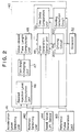
- Control unit 40 consists of an A/ D converter not shown in the figure, multiplexer, microcomputer, driving circuit 200 mentioned below, and of seating detection circuit 300, and in this control unit 40, each signals are input from each of acceleration level detecting unit 141 to detect the level of pushing the acceleration pedal (acceleration level), engine rotation detecting unit 142, reference pulse generating unit 143 which is attached to the driving shaft and generates pulses every time the driving shaft reaches the reference angle position, and from needle valve lift sensor 144 to detect the time point of the needle valve's lifting.
- acceleration level detecting unit 141 to detect the level of pushing the acceleration pedal (acceleration level)
- engine rotation detecting unit 142 engine rotation detecting unit 142
- reference pulse generating unit 143 which is attached to the driving shaft and generates pulses every time the driving shaft reaches the reference angle position
- needle valve lift sensor 144 to detect the time point of the needle valve's lifting.
- Fig. 2 shows, for convenience, a functional diagram for the processes carried out in the aforementioned control unit 40.
- the processes carried out in control unit 40 are explained below with reference to this diagram.
- the output signals from acceleration level detecting unit 141 and engine rotation detecting unit 142 are input in the desired injection level computation unit 46, and based on these input signals, the most desirable injection level suitable for the then driving conditions of the engine is computed from the map data and is put out as the desired injection level signals.
- Cam angle converter 47 inputs the aforementioned desired injection signals, computes, based on the specific map data, the cam angle necessary to obtain the aforementioned most desirable injection level, according to the engine rotation number, and puts out the result as cam angle signals.
- Valve-closed time length computation unit 48 receiving the aforementioned cam angle signals, converts the cam angle signals to the time necessary for the cam to rotate by the cam angle computed at cam angle conversion unit 47.
- the necessary time length (the valve-closed time length) T q is computed.
- Pulse generation control unit 49 adds the valve-closed time length T q computed at the aforementioned valve-closed time length computation unit 48 to the time delay T v computed at time delay computation unit 50, and determines the time to put out the driving pulse D p having the driving pulse width Td determined by the sum of T q and T v , to driving circuit 200; more specifically, it determines the most adequate timing to start the fuel-injection, on the bases of the reference signals generated from reference pulse generating unit 143, the injection timing signals generated from needle valve lift sensor 144, and the rotation signals generated from rotation detecting unit 142.
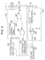
- Driving circuit 200 consists of high-frequency generation device 210, one-shot-pulse generation device 220, AND circuit 230, OR circuit 240, and electric field effect type transistor (FET) 250, as specifically shown in Fig. 3, and the driving pulse D p (shown in Fig. 4 (A)) generated from the aforementioned pulse generation control unit 49 is input in the aforementioned one-shot- pulse generation device 220, and in one of the input terminals of AND circuit 230.
- FET electric field effect type transistor
- One-shot-pulse generation device 220 generates pulse PO having a large duty ratio (100 % in this case), shown by the specific time length (t 1 - t 2 ) from the time point when the driving pulse D p rises, as shown in Fig. 4 (B).
- This specific time length is preliminarily defined on the bases of the experiments.
- AND circuit 230 high-frequency waves Hp are input as well as the aforementioned driving pulse D p , as shown in Fig. 4 (C) from high-frequency wave generation device 210, and thereby AND circuit 230 puts out pulse L o which becomes high-frequency waves only for the time length t 1 - t 3 , as shown in Fig. 4 (D).
- the pulse P o put out from the aforementioned one-shot-pulse generation device 220 and the pulse L o put out from AND circuit 230 are input in OR circuit 240, and thereby, as shown in Fig. 4 (E), the actual driving pulse Dr having a large duty ratio in the time length t1-t2 (forced time length) and a small duty ratio in the time length t 2 -t 3 (limited time length) is put out from OR circuit 240.
- This actual driving pulse Dr is input in the gate of FET 250 via resistor R, and by this actual driving pulse D r the drain and the source in FET 250 are conducted to each other to supply the current to solenoid 32 and to drive valve 23 in direction of closing.
- the motion of valve 23 can be accelerated by the pulse having a large duty ratio in the beginning of solenoid valve 20's driving when greater driving force is needed, and during the subsequent time period after the beginning of the valve's driving when the valve's closing needs to be detected, the actual voltage can be lowered by the pulse having a small duty ratio so as to make a changing point of the current (an inflection point in the current) more visible at the time of valve 23's seating.
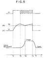
- Seating detection device 300 detects the valve 23's seating by detecting the curving point of the current generated when valve 23 seats in valve seat 24, and it consists of the resistor Rd, connected in series to solenoid 32, current detecting circuit 310 to detect the current by detecting the voltage on both sides of this resistor, comparator 320 to compare the voltage Vi corresponding to this detected current with the threshold voltage V p , and invertor 330.
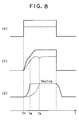
- This voltage value Vi gradually rises during the time forced length (t1 - t2), and gradually declines during the limited time length (t2 t3),until the seating time point (t4), being followed by the gradual increase that continues from the time point at which the seating begins until its completion (t3), as shown in Fig. 5 (F).
- the solenoid valve's seating time point can be, thus, detected from the characteristic that the current inflection point is formed at the time when solenoid valve 20 is seated.
- the threshold voltage V p having a specific level of voltage is input, and from this comparator 320, the seating signals are supplied to the time delay computation unit 50 and pulse generation control unit 49, since the output becomes L at the time point (t4) when the aforementioned voltage value Vi becomes lower than the threshold voltage V p , and the output of invertor 330 becomes H.
- the minimal point (inflection point) caused by the valve 23's seating was judged from the voltage, but the current inflection point for the seating may be judged by the differentiating signal by installing a differentiating circuit.
- valve 23's being pushed away from valve seat 24, that is shown by t3 - t5 in Fig. 5, is defined by the pushing force of spring 33.
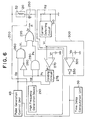
- the driving circuit 200 of this example consists of high- frequency generation device 210, two AND circuits 260, 290, OR circuit 295, resistor R, FET 250, comparator 270, and of invertor 280.
- the driving pulse D p (Fig. 7 (G)) put out from the aforementioned pulse generation control unit 49 is input in one end of AND circuit 260.
- signal Pi shown in Fig. 7 (I) is input via invertor 280.
- This signal Pi is formed at holding circuit 275, where driving pulse D p put out from pulse generation control unit 49 is input, as well as the signal Pi' that is put out from comparator 270 when the voltage Vi (Fig.
- This holding circuit 275 once the signal Pi' is input, defines its output signal, at this point, as Hi, and forms the signal Pi by retaining this condition until the completion time of the driving pulse D p .
- the output signal V L (Fig. 7 (L)) of AND circuit 260 forms a rectangular waveform having a duty ratio 100% for the time length t1 ⁇ t2, and is input in one end of OR circuit 295.
- high-frequency signal Pk (Fig. 7 (k)) that becomes high-frequency waves only for the limited time length (t2 - t3) that is formed when high-frequency waves Hp (Fig. 7 (J)) put out from the aforementioned high-frequency wave generation device and the aforementioned signal Pi is input in AND circuit 290.
- the same actual driving pulse Dr as in the aforementioned example can be obtained from the output of OR circuit 295.
- this driving circuit 200 unlike the aforementioned example, wherein the driving circuit's forced time length was defined as a specific time length form the result of the experiments, a specific consideration for defining the forced time length is not necessary, since the forced time length ends when the current reaches or exceeds a specific value.
- the forced time length wherein the duty ratio of the driving pulse supplied to the solenoid is large and the limited time length wherein the duty ratio is small are established; therefore, the responsiveness of the solenoid valve can be improved to be faster by the driving pulse having the large duty ratio during the forced time length, and the detection of the solenoid valve's seating can be performed definitely by the driving pulse having the small duty ratio during the limited time length.
Landscapes
- Engineering & Computer Science (AREA)
- Chemical & Material Sciences (AREA)
- Combustion & Propulsion (AREA)
- Mechanical Engineering (AREA)
- General Engineering & Computer Science (AREA)
- Physics & Mathematics (AREA)
- Electromagnetism (AREA)
- Electrical Control Of Air Or Fuel Supplied To Internal-Combustion Engine (AREA)
- Fuel-Injection Apparatus (AREA)
- Magnetically Actuated Valves (AREA)
Claims (6)
- Kraftstoffeinspritzpumpe (1), zumindest mit einem Kompressor (15) der in einen Zylinder (3) eingebaut ist, in den ein Plunger (4) verschieblich eingesetzt ist, mit einem Hochdruckdurchlaß (14), der den Kraftstoff im Kompressor (15) zu einer Düse (10) führt, und mit einem Kraftstoffzuführungsdurchlaß (34), der den von einer Niederdruckkraftstoffeinlaßseite zugeführten Kraftstoff dem Kompressor (15) zuführt, mit einem Magnetventil (20), das in den Kraftstoffzuführungsdurchlaß (34) zwischen der Hochdruckseite und der Niederdruckseite eingebaut und fähig ist, den Durchlaß zwischen der Hochdruck- und Niederdruckseite zu schließen wobei die Einspritzmenge der Kraftstoffeinspritzpumpe (1) durch Öffnen/Schließen des Magnetventils (20) reguliert wird, wobei diese Kraftstoffeinspritzpumpe (1) weiter aufweist:ein Soll-Einspritzlevel-Berechnungsmittel (46), um eine Ausgabezeit zu berechnen; ein Treiberimpulsbildungsmittel (200), um während einer Magnetventilschließbewegung einen Treiberimpuls (Dr) zu bilden, der aus einem Treiberimpulssegment (P0) mit einem großen relativen Einschaltverhältnis während einer ersten Zeitdauer und aus einem Treiberimpulssegment (L0) mit einem kleinen relativen Einschaltverhältnis in einer folgenden Zeitdauer innerhalb der durch die vorgenannte Ausgabezeit bestimmten Treiberzeitdauer des Magnetventils (20) zusammengesetzt ist;ein Magnetventiltreibermittel (240), um das Magnetventil (20) durch den von diesem Treiberimpulsbildungsmittel (200) gebildeten Treiberimpuls zu betätigen; ein Stromwellenformdetektormittel (310), um die dem Magnetventil (20) durch dieses Magnetventiltreibermittel (240) zugeführte Stromwellenform zu detektieren; ein Sitzdetektormittel (300), um den Zeitpunkt des Aufsitzens des Magnetventils aus der Stromwellenform zu detektieren.
- Kraftstoffeinspritzpumpe nach Anspruch 1, wobei die Zeitverzögerung beim Schließen des Ventils (23), die erforderlich ist, um den Kraftstoffzuführungsdurchlaß (34) abzusperren, ermittelt wird, durch Detektion eines Anderungspunktes des dem Elektromagneten (32) zugeführten Stromes, der dann auftritt, wenn das Ventil (23) auf dem Ventilsitz (24) aufsitzt, und durch Zählen der Zeitdauer von dem Zeitpunkt, wenn der Impuls, um das Magnetventil (20) zu betätigen, ausgegeben wird, bis zu dem Zeitpunkt, wenn das Ventil (23) sitzt.
- Kraftstoffeinspritzpumpe nach Anspruch 1 oder 2, mit einem ersten Generator (220), der den Impuls (P0) mit einem großen relativen Einschaltverhältnis in spezifischen Zeitintervallen für eine spezifische Zeitspanne erzeugt, und einem zweiten Generator (210), der den Impuls (L0) mit einem kleineren relativen Einschaltverhältnis als das des von dem ersten Generator (220) erzeugten Impulses (P0) erzeugt, wobei der von dem zweiten Generator (210) während der Magnetventilbetätigungszeitspanne ausgegebene Impuls (L0) und der von dem ersten Generator (220) ausgegebene Impuls (P0) in ein ODER-Gatter (240) eingegeben werden und so eine erzwungene Zeitdauer und eine begrenzte Zeitdauer für den Treiberimpuls (Dr) bilden.
- Kraftstoffeinspritzpumpe nach Anspruch 3, wobei die erzwungene Zeitdauer des Treiberimpulses (Dr) endet, wenn der dem Elektromagneten (32) zugeführte Strom einen bestimmten Wert überschreitet.
- Kraftstoffeinspritzpumpe nach einem der voranstehenden Ansprüche, wobei die Ventilschließzeitdauer bestimmt wird, indem ein gewünschter Einspritzlevel basierend auf einem Druckzustand eines Gaspedals und des Motorrotationszustands berechnet wird, indem der berechnete gewünschte Einspritzlevel in einen Nockenwinkel umgewandelt wird, der notwendig ist, um den Einspritzlevel zu erhalten, und indem nachfolgend die Zeit berechnet wird, die für den Nocken erforderlich ist, um über den Nockenwinkel zu rotieren.
- Kraftstoffeinspritzpumpe nach einem der voranstehenden Ansprüche, wobei das Magnetventil (20) sich auf eine Seite der Einspritzpumpe (1) erstreckend eingebaut ist und eine verschiebbare Stange (22) mit dem Ventil (23) eingefügt ist, ein Ventilgehäuse (21) einen Ventilsitz (24) für das Ventil (23) aufweist, um darauf aufzusitzen, ein Kopf (25) an dem Ventilgehäuse (21) angebracht ist, der das Ventil (23) überdeckt und einen Raum (27) bildet, um das Ventil (23) zwischen sich und dem Ventilgehäuse (21) unterzubringen, ein Elektromagnet (32) einem an der Stange (22) befestigten Anker (31) zugewandt und an der dem Kopf (25) gegenüberliegenden Seite des Ventilgehäuses (21) angeordnet ist und eine Feder (33) das Ventil (23) von dem Ventilsitz (24) permanent wegdrückt, wobei der Kraftstoffzuführungsdurchlaß (34) in die Nähe des Ventilaufnahmeraums (27) und der Stange (22) reicht, der mit dem Aufnahmeraum (27) zur Zeit der Ventilöffnung verbunden ist.
Priority Applications (3)
| Application Number | Priority Date | Filing Date | Title |
|---|---|---|---|
| EP95105010A EP0671558B1 (de) | 1992-03-26 | 1993-03-23 | Kraftstoff-Einspritzvorrichtung |
| EP95105009A EP0671557B1 (de) | 1992-03-26 | 1993-03-23 | Kraftstoff-Einspritzvorrichtung |
| EP95105008A EP0669457B1 (de) | 1992-03-26 | 1993-03-23 | Kraftstoff-Einspritzvorrichtung |
Applications Claiming Priority (8)
| Application Number | Priority Date | Filing Date | Title |
|---|---|---|---|
| JP100688/92 | 1992-03-26 | ||
| JP4100688A JPH05272377A (ja) | 1992-03-26 | 1992-03-26 | 燃料噴射装置 |
| JP10068992A JP3165930B2 (ja) | 1992-03-26 | 1992-03-26 | 燃料噴射装置 |
| JP10068692A JP3245718B2 (ja) | 1992-03-26 | 1992-03-26 | 燃料噴射装置 |
| JP100686/92 | 1992-03-26 | ||
| JP10068792A JP3245719B2 (ja) | 1992-03-26 | 1992-03-26 | 燃料噴射装置 |
| JP100687/92 | 1992-03-26 | ||
| JP100689/92 | 1992-03-26 |
Related Child Applications (4)
| Application Number | Title | Priority Date | Filing Date |
|---|---|---|---|
| EP95105009.5 Division-Into | 1993-03-23 | ||
| EP95105010.3 Division-Into | 1993-03-23 | ||
| EP95105008A Division EP0669457B1 (de) | 1992-03-26 | 1993-03-23 | Kraftstoff-Einspritzvorrichtung |
| EP95105008.7 Division-Into | 1993-03-23 |
Publications (4)
| Publication Number | Publication Date |
|---|---|
| EP0563760A2 EP0563760A2 (de) | 1993-10-06 |
| EP0563760A3 EP0563760A3 (en) | 1993-12-15 |
| EP0563760B1 true EP0563760B1 (de) | 1996-08-28 |
| EP0563760B2 EP0563760B2 (de) | 1999-05-12 |
Family
ID=27468851
Family Applications (4)
| Application Number | Title | Priority Date | Filing Date |
|---|---|---|---|
| EP95105009A Expired - Lifetime EP0671557B1 (de) | 1992-03-26 | 1993-03-23 | Kraftstoff-Einspritzvorrichtung |
| EP93104793A Expired - Lifetime EP0563760B2 (de) | 1992-03-26 | 1993-03-23 | Kraftstoff-Einspritzvorrichtung |
| EP95105010A Expired - Lifetime EP0671558B1 (de) | 1992-03-26 | 1993-03-23 | Kraftstoff-Einspritzvorrichtung |
| EP95105008A Expired - Lifetime EP0669457B1 (de) | 1992-03-26 | 1993-03-23 | Kraftstoff-Einspritzvorrichtung |
Family Applications Before (1)
| Application Number | Title | Priority Date | Filing Date |
|---|---|---|---|
| EP95105009A Expired - Lifetime EP0671557B1 (de) | 1992-03-26 | 1993-03-23 | Kraftstoff-Einspritzvorrichtung |
Family Applications After (2)
| Application Number | Title | Priority Date | Filing Date |
|---|---|---|---|
| EP95105010A Expired - Lifetime EP0671558B1 (de) | 1992-03-26 | 1993-03-23 | Kraftstoff-Einspritzvorrichtung |
| EP95105008A Expired - Lifetime EP0669457B1 (de) | 1992-03-26 | 1993-03-23 | Kraftstoff-Einspritzvorrichtung |
Country Status (3)
| Country | Link |
|---|---|
| US (1) | US5375575A (de) |
| EP (4) | EP0671557B1 (de) |
| DE (4) | DE69320826T2 (de) |
Families Citing this family (51)
| Publication number | Priority date | Publication date | Assignee | Title |
|---|---|---|---|---|
| EP0671557B1 (de) * | 1992-03-26 | 1998-09-02 | Zexel Corporation | Kraftstoff-Einspritzvorrichtung |
| JPH0777098A (ja) * | 1993-09-07 | 1995-03-20 | Zexel Corp | 内燃機関の燃料噴射時期制御装置 |
| IT1261360B (it) * | 1993-11-19 | 1996-05-20 | Fiat Ricerche | Sistema elettronico per il controllo di carichi induttivi di iniettoridi un impianto di alimentazione per motori a combustione interna |
| DE19513878A1 (de) * | 1995-04-12 | 1996-10-17 | Bosch Gmbh Robert | Verfahren und Vorrichtung zur Steuerung eines elektromagnetischen Verbrauchers |
| US5862995A (en) * | 1996-04-01 | 1999-01-26 | Diesel Technology Company | High pressure fluid passage sealing for internal combustion engine fuel injectors and method of making same |
| JP3572433B2 (ja) * | 1997-01-31 | 2004-10-06 | 日産自動車株式会社 | ディーゼルエンジン用燃料噴射ポンプの燃料噴射時期制御装置 |
| DE19723931A1 (de) | 1997-06-06 | 1998-12-10 | Siemens Ag | Einrichtung zum Steuern eines elektromechanischen Stellgeräts |
| US5975053A (en) * | 1997-11-25 | 1999-11-02 | Caterpillar Inc. | Electronic fuel injection quiet operation |
| US6311674B1 (en) | 1998-04-15 | 2001-11-06 | Denso Corporation | Fuel injection system for internal combustion engine |
| JP4118414B2 (ja) | 1998-10-29 | 2008-07-16 | サンデン株式会社 | 可変容量圧縮機の容量制御弁の制御回路 |
| DE69938615T2 (de) * | 1999-02-09 | 2009-06-10 | Hitachi, Ltd. | Hochdruckbrennstoffpumpe für eine Brennkraftmaschine |
| JP3633388B2 (ja) * | 1999-08-04 | 2005-03-30 | トヨタ自動車株式会社 | 内燃機関の高圧燃料ポンプ制御装置 |
| JP2001152940A (ja) * | 1999-11-24 | 2001-06-05 | Mitsubishi Electric Corp | 燃料噴射システム |
| US6257205B1 (en) * | 1999-12-22 | 2001-07-10 | Ford Global Technologies, Inc. | System for controlling a fuel injector |
| JP3842002B2 (ja) * | 2000-03-01 | 2006-11-08 | 三菱電機株式会社 | 可変吐出量燃料供給装置 |
| DE50211745D1 (de) | 2001-08-16 | 2008-04-03 | Bosch Gmbh Robert | Verfahren und vorrichtung zur steuerung eines elektromagnetischen verbrauchers |
| JP3851140B2 (ja) | 2001-10-30 | 2006-11-29 | ボッシュ株式会社 | 流量制御用電磁比例制御弁の駆動方法 |
| TWI259235B (en) | 2002-03-26 | 2006-08-01 | Mikuni Kogyo Kk | Fuel injection controller and controlling method |
| US7153286B2 (en) | 2002-05-24 | 2006-12-26 | Baxter International Inc. | Automated dialysis system |
| WO2006060545A1 (en) * | 2004-12-03 | 2006-06-08 | Stanadyne Corporation | Reduced noise solenoid controlled fuel pump |
| JP4227965B2 (ja) * | 2005-02-28 | 2009-02-18 | 三菱重工業株式会社 | 電磁制御燃料噴射装置 |
| US7430102B2 (en) * | 2006-01-04 | 2008-09-30 | Honeywell International Inc. | Pulse width modulated servo clutch driver |
| FR2909724B1 (fr) * | 2006-12-12 | 2009-02-27 | Renault Sas | Systeme d'alimentation en carburant pour moteur a combustion interne et procede de commande correspondant |
| JP4719140B2 (ja) * | 2006-12-20 | 2011-07-06 | 三菱重工業株式会社 | 電磁弁装置及びこれを備えたエンジンの燃料噴射装置 |
| GB2450523A (en) * | 2007-06-28 | 2008-12-31 | Woodward Governor Co | Method and means of controlling a solenoid operated valve |
| US8027572B2 (en) | 2008-02-22 | 2011-09-27 | Baxter International Inc. | Dialysis machine having multiple line voltage heater |
| US7782590B2 (en) * | 2008-02-22 | 2010-08-24 | Baxter International Inc. | Medical fluid machine having solenoid control system with reduced hold current |
| US7746620B2 (en) | 2008-02-22 | 2010-06-29 | Baxter International Inc. | Medical fluid machine having solenoid control system with temperature compensation |
| JP4587133B2 (ja) | 2008-06-04 | 2010-11-24 | 株式会社デンソー | 燃料供給装置 |
| DE102009003211B4 (de) * | 2009-05-19 | 2019-08-01 | Robert Bosch Gmbh | Verfahren zur Ansteuerung von Injektoren in einer Brennkraftmaschine |
| US9435459B2 (en) | 2009-06-05 | 2016-09-06 | Baxter International Inc. | Solenoid pinch valve apparatus and method for medical fluid applications having reduced noise production |
| US8681468B2 (en) | 2009-10-28 | 2014-03-25 | Raytheon Company | Method of controlling solenoid valve |
| DE102010001004A1 (de) * | 2010-01-19 | 2011-07-21 | Robert Bosch GmbH, 70469 | Verfahren und Vorrichtung zur Ansteuerung von Aktuatoren |
| DE102010039832A1 (de) * | 2010-08-26 | 2012-03-01 | Continental Automotive Gmbh | Verfahren und Vorrichtung zum Erkennen eines Erreichens eines Schließpunkts eines hydraulischen Ventils |
| US20120166067A1 (en) * | 2010-12-27 | 2012-06-28 | GM Global Technology Operations LLC | Method for controlling a fuel injector |
| DE102011075271B4 (de) * | 2011-05-04 | 2014-03-06 | Continental Automotive Gmbh | Verfahren und Vorrichtung zum Steuern eines Ventils |
| JP5644818B2 (ja) * | 2012-08-01 | 2014-12-24 | 株式会社デンソー | 燃料噴射制御装置 |
| JP5790611B2 (ja) * | 2012-09-13 | 2015-10-07 | 株式会社デンソー | 燃料噴射制御装置 |
| DE102012218370B4 (de) | 2012-10-09 | 2015-04-02 | Continental Automotive Gmbh | Verfahren und Vorrichtung zum Steuern eines Ventils |
| JP6169404B2 (ja) | 2013-04-26 | 2017-07-26 | 日立オートモティブシステムズ株式会社 | 電磁弁の制御装置及びそれを用いた内燃機関の制御装置 |
| WO2015004988A1 (ja) * | 2013-07-10 | 2015-01-15 | 日立オートモティブシステムズ株式会社 | 内燃機関の制御装置 |
| DE102013220407B4 (de) * | 2013-10-10 | 2022-09-29 | Vitesco Technologies GmbH | Verfahren und Vorrichtung zum Betreiben eines Einspritzventils |
| CN103527338B (zh) * | 2013-10-29 | 2016-03-16 | 潍柴动力股份有限公司 | 一种喷油修正方法及系统 |
| DE102014203364B4 (de) | 2014-02-25 | 2023-03-23 | Vitesco Technologies GmbH | Verfahren und Vorrichtung zum Betrieb eines Ventils, insbesondere für ein Speichereinspritzsystem |
| JP6464076B2 (ja) * | 2015-11-17 | 2019-02-06 | ヤンマー株式会社 | 燃料噴射ポンプ |
| DE102016204518B3 (de) * | 2016-03-18 | 2017-02-23 | Continental Automotive Gmbh | Ansteuerung von Kraftstoffinjektoren bei variierender Bordnetzspannung |
| EP3385528B1 (de) * | 2017-04-06 | 2020-10-28 | Vitesco Technologies GmbH | Verfahren zur erkennung einer schaltstelle eines schaltbaren magnetventils, elektronische schaltung, pumpe und kraftfahrzeug |
| JP7139223B2 (ja) * | 2018-11-12 | 2022-09-20 | 日立Astemo株式会社 | 燃料噴射装置の制御装置 |
| CN110107726B (zh) * | 2019-05-08 | 2020-05-22 | 合肥工业大学 | 一种减少开关电磁阀关闭时延的控制方法 |
| DE102021115937A1 (de) * | 2020-06-26 | 2021-12-30 | Transportation Ip Holdings, Llc | Verfahren und systeme zur kraftstoffinjektorsteuerung |
| DE102020213169B3 (de) * | 2020-10-19 | 2022-02-03 | Vitesco Technologies GmbH | Verfahren und Vorrichtung zur Bewegungsdiagnose eines Ankers eines Magnetventils |
Family Cites Families (23)
| Publication number | Priority date | Publication date | Assignee | Title |
|---|---|---|---|---|
| JPS5773620A (en) * | 1980-10-27 | 1982-05-08 | Diesel Kiki Co Ltd | Method and device for detecting fault |
| DE3148671A1 (de) * | 1981-12-09 | 1983-07-21 | Robert Bosch Gmbh, 7000 Stuttgart | Kraftstoffeinspritzvorrichtung fuer brennkraftmaschinen, insbesondere fuer dieselmotoren |
| US4503825A (en) * | 1982-04-02 | 1985-03-12 | Bendix Corporation | Diesel fuel system |
| US4535743A (en) * | 1983-04-15 | 1985-08-20 | Nippon Soken, Inc. | Fuel injection apparatus for an internal combustion engine |
| DE3344662A1 (de) * | 1983-12-09 | 1985-06-13 | Mannesmann Rexroth GmbH, 8770 Lohr | Schaltungsanordnung zur ansteuerung eines magnetventils, insbesondere fuer kraftstoffeinspritzventile |
| JPH07111151B2 (ja) * | 1984-01-10 | 1995-11-29 | 日本電装株式会社 | デイ−ゼルエンジン用燃料噴射量制御装置 |
| JPS61212635A (ja) * | 1985-03-18 | 1986-09-20 | Toyota Motor Corp | 燃料噴射ポンプ用電磁弁の駆動方法 |
| JPH0754101B2 (ja) * | 1985-03-29 | 1995-06-07 | 日本電装株式会社 | 内燃機関の燃料噴射量制御装置 |
| IT1183828B (it) * | 1985-05-10 | 1987-10-22 | Weber Spa | Sistema di controllo di iniettori di carburante per l'apertura asincrona rispetto alle fasi di un motore endotermico |
| JPH07116975B2 (ja) * | 1985-05-23 | 1995-12-18 | 株式会社ゼクセル | 燃料噴射装置 |
| US4884549A (en) * | 1986-04-21 | 1989-12-05 | Stanadyne Automotive Corp. | Method and apparatus for regulating fuel injection timing and quantity |
| JPS6321346A (ja) * | 1986-07-12 | 1988-01-28 | Diesel Kiki Co Ltd | 燃料噴射装置 |
| JP2521086B2 (ja) * | 1987-04-06 | 1996-07-31 | 株式会社ゼクセル | 燃料噴射ポンプの制御装置 |
| DE3711744A1 (de) * | 1987-04-07 | 1988-10-27 | Bosch Gmbh Robert | Verfahren und vorrichtung zur steuerung der kraftstoffeinspritzmenge |
| JP2576958B2 (ja) * | 1987-09-28 | 1997-01-29 | 株式会社ゼクセル | 電磁弁制御式の分配型燃料噴射装置 |
| US4982331A (en) * | 1988-01-25 | 1991-01-01 | Mitsubishi Denki Kabushiki Kaisha | Fuel injector control apparatus |
| DE3816165A1 (de) * | 1988-05-11 | 1989-11-23 | Bosch Gmbh Robert | Steuersystem fuer eine dieselbrennkraftmaschine |
| GB2224786B (en) * | 1988-09-21 | 1992-09-23 | Toyota Motor Co Ltd | A fuel injection device |
| DE4006084A1 (de) * | 1990-02-27 | 1991-08-29 | Bosch Gmbh Robert | Verfahren und verminderung der resteinspritzmenge von einspritzpumpen |
| DE4010450A1 (de) * | 1990-03-31 | 1991-10-02 | Bosch Gmbh Robert | Kraftstoffeinspritzeinrichtung fuer einspritzbrennkraftmaschinen |
| DE4120461C2 (de) * | 1991-06-21 | 2000-09-14 | Bosch Gmbh Robert | Verfahren und Einrichtung zur Steuerung eines magnetventilgesteuerten Kraftstoffzumeßsystems |
| JPH05248300A (ja) * | 1992-03-04 | 1993-09-24 | Zexel Corp | 燃料噴射装置 |
| EP0671557B1 (de) * | 1992-03-26 | 1998-09-02 | Zexel Corporation | Kraftstoff-Einspritzvorrichtung |
-
1993
- 1993-03-23 EP EP95105009A patent/EP0671557B1/de not_active Expired - Lifetime
- 1993-03-23 EP EP93104793A patent/EP0563760B2/de not_active Expired - Lifetime
- 1993-03-23 DE DE69320826T patent/DE69320826T2/de not_active Expired - Fee Related
- 1993-03-23 EP EP95105010A patent/EP0671558B1/de not_active Expired - Lifetime
- 1993-03-23 DE DE69320829T patent/DE69320829T2/de not_active Expired - Fee Related
- 1993-03-23 DE DE69304234T patent/DE69304234T3/de not_active Expired - Fee Related
- 1993-03-23 DE DE69320830T patent/DE69320830T2/de not_active Expired - Fee Related
- 1993-03-23 EP EP95105008A patent/EP0669457B1/de not_active Expired - Lifetime
- 1993-03-25 US US08/036,863 patent/US5375575A/en not_active Expired - Fee Related
Also Published As
| Publication number | Publication date |
|---|---|
| DE69320829T2 (de) | 1999-01-21 |
| US5375575A (en) | 1994-12-27 |
| DE69320826T2 (de) | 1999-01-21 |
| DE69304234T2 (de) | 1997-01-02 |
| DE69320829D1 (de) | 1998-10-08 |
| EP0671558B1 (de) | 1998-09-02 |
| DE69304234D1 (de) | 1996-10-02 |
| DE69320826D1 (de) | 1998-10-08 |
| EP0671558A1 (de) | 1995-09-13 |
| DE69320830D1 (de) | 1998-10-08 |
| EP0669457A1 (de) | 1995-08-30 |
| EP0669457B1 (de) | 1998-09-02 |
| EP0671557B1 (de) | 1998-09-02 |
| EP0563760B2 (de) | 1999-05-12 |
| EP0563760A2 (de) | 1993-10-06 |
| EP0563760A3 (en) | 1993-12-15 |
| DE69304234T3 (de) | 1999-07-15 |
| DE69320830T2 (de) | 1999-01-14 |
| EP0671557A1 (de) | 1995-09-13 |
Similar Documents
| Publication | Publication Date | Title |
|---|---|---|
| EP0563760B1 (de) | Kraftstoff-Einspritzvorrichtung | |
| EP0559136B1 (de) | Kraftstoffeinspritzvorrichtung | |
| EP0959238B1 (de) | Treiberschaltung | |
| CN107110053B (zh) | 燃料喷射装置的驱动装置 | |
| US5720261A (en) | Valve controller systems and methods and fuel injection systems utilizing the same | |
| CA1300218C (en) | Method and apparatus for controlling a solenoid operated fuel injector | |
| US5803049A (en) | Fuel System | |
| US6123092A (en) | Electromagnetic solenoid valve drive circuit | |
| SE515565C2 (sv) | Metod för reglering av samt detektering av läget hos en solenoidpåverkad armatur | |
| US6497221B1 (en) | Feedback tailoring of fuel injector drive signal | |
| CN113167185B (zh) | 燃料喷射控制装置 | |
| JP3245718B2 (ja) | 燃料噴射装置 | |
| US20220099040A1 (en) | Control Device for Fuel Injection Device | |
| JP3245719B2 (ja) | 燃料噴射装置 | |
| JP2000130230A (ja) | エンジンの燃料噴射制御装置 | |
| JP3165930B2 (ja) | 燃料噴射装置 | |
| JP2591267B2 (ja) | 内燃機関の燃料噴射装置 | |
| JPH1193799A (ja) | 燃料噴射弁およびこれを用いる燃料噴射システム | |
| WO2023228666A1 (en) | Control device and method for controlling an injector | |
| GB2323411A (en) | Solenoid-actuated control valve for i.c. engine fuel injection system | |
| JPH10141173A (ja) | 燃料噴射装置 |
Legal Events
| Date | Code | Title | Description |
|---|---|---|---|
| PUAI | Public reference made under article 153(3) epc to a published international application that has entered the european phase |
Free format text: ORIGINAL CODE: 0009012 |
|
| AK | Designated contracting states |
Kind code of ref document: A2 Designated state(s): DE GB |
|
| PUAL | Search report despatched |
Free format text: ORIGINAL CODE: 0009013 |
|
| AK | Designated contracting states |
Kind code of ref document: A3 Designated state(s): DE GB |
|
| 17P | Request for examination filed |
Effective date: 19940201 |
|
| 17Q | First examination report despatched |
Effective date: 19950203 |
|
| GRAG | Despatch of communication of intention to grant |
Free format text: ORIGINAL CODE: EPIDOS AGRA |
|
| GRAH | Despatch of communication of intention to grant a patent |
Free format text: ORIGINAL CODE: EPIDOS IGRA |
|
| GRAH | Despatch of communication of intention to grant a patent |
Free format text: ORIGINAL CODE: EPIDOS IGRA |
|
| GRAA | (expected) grant |
Free format text: ORIGINAL CODE: 0009210 |
|
| AK | Designated contracting states |
Kind code of ref document: B1 Designated state(s): DE GB |
|
| XX | Miscellaneous (additional remarks) |
Free format text: TEILANMELDUNG 95105008.7 EINGEREICHT AM 23/03/93. |
|
| REF | Corresponds to: |
Ref document number: 69304234 Country of ref document: DE Date of ref document: 19961002 |
|
| PLBI | Opposition filed |
Free format text: ORIGINAL CODE: 0009260 |
|
| PLAV | Examination of admissibility of opposition |
Free format text: ORIGINAL CODE: EPIDOS OPEX |
|
| 26 | Opposition filed |
Opponent name: ROBERT BOSCH GMBH Effective date: 19970526 |
|
| PLAV | Examination of admissibility of opposition |
Free format text: ORIGINAL CODE: EPIDOS OPEX |
|
| PLBF | Reply of patent proprietor to notice(s) of opposition |
Free format text: ORIGINAL CODE: EPIDOS OBSO |
|
| PLBF | Reply of patent proprietor to notice(s) of opposition |
Free format text: ORIGINAL CODE: EPIDOS OBSO |
|
| PLBF | Reply of patent proprietor to notice(s) of opposition |
Free format text: ORIGINAL CODE: EPIDOS OBSO |
|
| PLAW | Interlocutory decision in opposition |
Free format text: ORIGINAL CODE: EPIDOS IDOP |
|
| PLAW | Interlocutory decision in opposition |
Free format text: ORIGINAL CODE: EPIDOS IDOP |
|
| PUAH | Patent maintained in amended form |
Free format text: ORIGINAL CODE: 0009272 |
|
| STAA | Information on the status of an ep patent application or granted ep patent |
Free format text: STATUS: PATENT MAINTAINED AS AMENDED |
|
| 27A | Patent maintained in amended form |
Effective date: 19990512 |
|
| AK | Designated contracting states |
Kind code of ref document: B2 Designated state(s): DE GB |
|
| REG | Reference to a national code |
Ref country code: GB Ref legal event code: IF02 |
|
| PGFP | Annual fee paid to national office [announced via postgrant information from national office to epo] |
Ref country code: GB Payment date: 20040317 Year of fee payment: 12 |
|
| PGFP | Annual fee paid to national office [announced via postgrant information from national office to epo] |
Ref country code: DE Payment date: 20040401 Year of fee payment: 12 |
|
| PG25 | Lapsed in a contracting state [announced via postgrant information from national office to epo] |
Ref country code: GB Free format text: LAPSE BECAUSE OF NON-PAYMENT OF DUE FEES Effective date: 20050323 |
|
| PG25 | Lapsed in a contracting state [announced via postgrant information from national office to epo] |
Ref country code: DE Free format text: LAPSE BECAUSE OF NON-PAYMENT OF DUE FEES Effective date: 20051001 |
|
| GBPC | Gb: european patent ceased through non-payment of renewal fee |
Effective date: 20050323 |