EP0559808B1 - A catalyst structure having integral heat exchange (ii) - Google Patents
A catalyst structure having integral heat exchange (ii) Download PDFInfo
- Publication number
- EP0559808B1 EP0559808B1 EP92902357A EP92902357A EP0559808B1 EP 0559808 B1 EP0559808 B1 EP 0559808B1 EP 92902357 A EP92902357 A EP 92902357A EP 92902357 A EP92902357 A EP 92902357A EP 0559808 B1 EP0559808 B1 EP 0559808B1
- Authority
- EP
- European Patent Office
- Prior art keywords
- catalyst
- catalyst structure
- passageways
- catalytic material
- catalytic
- Prior art date
- Legal status (The legal status is an assumption and is not a legal conclusion. Google has not performed a legal analysis and makes no representation as to the accuracy of the status listed.)
- Expired - Lifetime
Links
Images



Classifications
-
- B—PERFORMING OPERATIONS; TRANSPORTING
- B01—PHYSICAL OR CHEMICAL PROCESSES OR APPARATUS IN GENERAL
- B01J—CHEMICAL OR PHYSICAL PROCESSES, e.g. CATALYSIS OR COLLOID CHEMISTRY; THEIR RELEVANT APPARATUS
- B01J21/00—Catalysts comprising the elements, oxides, or hydroxides of magnesium, boron, aluminium, carbon, silicon, titanium, zirconium, or hafnium
- B01J21/06—Silicon, titanium, zirconium or hafnium; Oxides or hydroxides thereof
- B01J21/066—Zirconium or hafnium; Oxides or hydroxides thereof
-
- B—PERFORMING OPERATIONS; TRANSPORTING
- B01—PHYSICAL OR CHEMICAL PROCESSES OR APPARATUS IN GENERAL
- B01D—SEPARATION
- B01D53/00—Separation of gases or vapours; Recovering vapours of volatile solvents from gases; Chemical or biological purification of waste gases, e.g. engine exhaust gases, smoke, fumes, flue gases, aerosols
- B01D53/34—Chemical or biological purification of waste gases
- B01D53/74—General processes for purification of waste gases; Apparatus or devices specially adapted therefor
- B01D53/86—Catalytic processes
- B01D53/8621—Removing nitrogen compounds
- B01D53/8625—Nitrogen oxides
- B01D53/8628—Processes characterised by a specific catalyst
-
- B—PERFORMING OPERATIONS; TRANSPORTING
- B01—PHYSICAL OR CHEMICAL PROCESSES OR APPARATUS IN GENERAL
- B01J—CHEMICAL OR PHYSICAL PROCESSES, e.g. CATALYSIS OR COLLOID CHEMISTRY; THEIR RELEVANT APPARATUS
- B01J23/00—Catalysts comprising metals or metal oxides or hydroxides, not provided for in group B01J21/00
- B01J23/38—Catalysts comprising metals or metal oxides or hydroxides, not provided for in group B01J21/00 of noble metals
- B01J23/40—Catalysts comprising metals or metal oxides or hydroxides, not provided for in group B01J21/00 of noble metals of the platinum group metals
- B01J23/42—Platinum
-
- B—PERFORMING OPERATIONS; TRANSPORTING
- B01—PHYSICAL OR CHEMICAL PROCESSES OR APPARATUS IN GENERAL
- B01J—CHEMICAL OR PHYSICAL PROCESSES, e.g. CATALYSIS OR COLLOID CHEMISTRY; THEIR RELEVANT APPARATUS
- B01J23/00—Catalysts comprising metals or metal oxides or hydroxides, not provided for in group B01J21/00
- B01J23/38—Catalysts comprising metals or metal oxides or hydroxides, not provided for in group B01J21/00 of noble metals
- B01J23/40—Catalysts comprising metals or metal oxides or hydroxides, not provided for in group B01J21/00 of noble metals of the platinum group metals
- B01J23/44—Palladium
-
- B—PERFORMING OPERATIONS; TRANSPORTING
- B01—PHYSICAL OR CHEMICAL PROCESSES OR APPARATUS IN GENERAL
- B01J—CHEMICAL OR PHYSICAL PROCESSES, e.g. CATALYSIS OR COLLOID CHEMISTRY; THEIR RELEVANT APPARATUS
- B01J35/00—Catalysts, in general, characterised by their form or physical properties
- B01J35/50—Catalysts, in general, characterised by their form or physical properties characterised by their shape or configuration
- B01J35/56—Foraminous structures having flow-through passages or channels, e.g. grids or three-dimensional [3D] monoliths
-
- F—MECHANICAL ENGINEERING; LIGHTING; HEATING; WEAPONS; BLASTING
- F01—MACHINES OR ENGINES IN GENERAL; ENGINE PLANTS IN GENERAL; STEAM ENGINES
- F01N—GAS-FLOW SILENCERS OR EXHAUST APPARATUS FOR MACHINES OR ENGINES IN GENERAL; GAS-FLOW SILENCERS OR EXHAUST APPARATUS FOR INTERNAL-COMBUSTION ENGINES
- F01N3/00—Exhaust or silencing apparatus having means for purifying, rendering innocuous, or otherwise treating exhaust
- F01N3/08—Exhaust or silencing apparatus having means for purifying, rendering innocuous, or otherwise treating exhaust for rendering innocuous
- F01N3/10—Exhaust or silencing apparatus having means for purifying, rendering innocuous, or otherwise treating exhaust for rendering innocuous by thermal or catalytic conversion of noxious components of exhaust
- F01N3/24—Exhaust or silencing apparatus having means for purifying, rendering innocuous, or otherwise treating exhaust for rendering innocuous by thermal or catalytic conversion of noxious components of exhaust characterised by constructional aspects of converting apparatus
- F01N3/28—Construction of catalytic reactors
- F01N3/2803—Construction of catalytic reactors characterised by structure, by material or by manufacturing of catalyst support
- F01N3/2807—Metal other than sintered metal
- F01N3/281—Metallic honeycomb monoliths made of stacked or rolled sheets, foils or plates
-
- B—PERFORMING OPERATIONS; TRANSPORTING
- B01—PHYSICAL OR CHEMICAL PROCESSES OR APPARATUS IN GENERAL
- B01J—CHEMICAL OR PHYSICAL PROCESSES, e.g. CATALYSIS OR COLLOID CHEMISTRY; THEIR RELEVANT APPARATUS
- B01J21/00—Catalysts comprising the elements, oxides, or hydroxides of magnesium, boron, aluminium, carbon, silicon, titanium, zirconium, or hafnium
- B01J21/06—Silicon, titanium, zirconium or hafnium; Oxides or hydroxides thereof
- B01J21/063—Titanium; Oxides or hydroxides thereof
-
- F—MECHANICAL ENGINEERING; LIGHTING; HEATING; WEAPONS; BLASTING
- F01—MACHINES OR ENGINES IN GENERAL; ENGINE PLANTS IN GENERAL; STEAM ENGINES
- F01N—GAS-FLOW SILENCERS OR EXHAUST APPARATUS FOR MACHINES OR ENGINES IN GENERAL; GAS-FLOW SILENCERS OR EXHAUST APPARATUS FOR INTERNAL-COMBUSTION ENGINES
- F01N2330/00—Structure of catalyst support or particle filter
- F01N2330/02—Metallic plates or honeycombs, e.g. superposed or rolled-up corrugated or otherwise deformed sheet metal
-
- F—MECHANICAL ENGINEERING; LIGHTING; HEATING; WEAPONS; BLASTING
- F01—MACHINES OR ENGINES IN GENERAL; ENGINE PLANTS IN GENERAL; STEAM ENGINES
- F01N—GAS-FLOW SILENCERS OR EXHAUST APPARATUS FOR MACHINES OR ENGINES IN GENERAL; GAS-FLOW SILENCERS OR EXHAUST APPARATUS FOR INTERNAL-COMBUSTION ENGINES
- F01N2330/00—Structure of catalyst support or particle filter
- F01N2330/30—Honeycomb supports characterised by their structural details
- F01N2330/32—Honeycomb supports characterised by their structural details characterised by the shape, form or number of corrugations of plates, sheets or foils
Definitions
- This invention is a catalyst structure having integral heat exchange surfaces. This feature allows use of the structure in highly exothermic process, such as a combustion process, while maintaining the catalyst and the structure wall at a temperature below the adiabatic combustion temperature of the combustible gas mixture.
- US-A-4870824 refers to catalytic combustor units consisting of a series of generally parallel passages, some of which have a catalyst coating, and some of which do not.
- the material for supporting the is ceramic.
- NO x an equilibrium mixture mostly of NO, but also containing very minor amounts of NO 2
- NO x may be dealt with either by controlling the combustion process to minimize NO x production or by later removal. Removal of NO x , once produced, is a difficult task because of its relative stability and its low concentrations in most exhaust gases.
- One solution used in automobiles is the use of carbon monoxide to reduce NO x to nitrogen while oxidizing the carbon monoxide to carbon dioxide.
- the need to react two pollutants also speaks to a conclusion that the initial combustion reaction was inefficient.
- the NO x abatement process chosen must not substantially conflict with the goal for which the combustion gas was created, i.e., the recovery of its heat value in a turbine, boiler, or furnace.
- the later Kokai discloses a process for the combustion of a fuel gas, in this case a blast furnace off-gas, using a catalyst structure such as that shown in the earlier Kokai or a structure of concentric cylinders in which alternating annular spaces in the support are coated with catalyst.
- a catalyst structure such as that shown in the earlier Kokai or a structure of concentric cylinders in which alternating annular spaces in the support are coated with catalyst.
- Neither Kokai suggest the use of metal monoliths of any configuration in the processes.
- This invention is both a catalyst structure suitable for use in a combustion process and a method of using that catalyst structure in a combustion process partially to burn a fuel/air mixture but maintain the catalyst and the catalyst support at a relatively low temperature.
- the catalyst structure desirably comprises a support and a combustion catalyst.
- the support is preferably metal. It may be corrugated and rolled or otherwise assembled in such a way that the combusting gas flows from end to end through the length of the corrugations.
- the catalyst is placed only on a portion of the corrugations in such a way that the catalyst is in heat exchange relationship to a substantially noncatalytic surface. The heat produced on the catalyst flows thorough the structure wall to the flowing gas at the opposite non-catalytic wall. The heat also flows to the adjacent combusted gas.
- the catalyst and its structure provide an exceptionally stable and temperature moderated structure having long life.
- FIGS 1A, 1B, 1C, 2A, and 2B schematically depict various forms of the inventive catalyst structure.
- FIGS 3A and 3B depict the operation of the structure.
- Figures 4A, 4B, 5, 6A, and 6B show various configurations of the inventive catalytic structure having catalytic material on a single side of the support.
- FIGS 7 to 9 use temperature graphs showing operation of the inventive catalyst structure.
- This invention is a catalyst structure which is particularly useful in fuel combustion processes.
- the structure is preferably a platinum-group, metal-based catalyst on a metal monolith.
- the metal monolith is assembled from or fabricated from metallic materials having a catalytic surface and an adjunct non-catalytic surface.
- One side of the catalyst structure component has catalyst upon it and the other side of the catalyst structure component is essentially catalyst-free.
- the preferred supports for this catalytic zone are metallic.
- Metallic supports in the form of honeycombs, spiral rolls of corrugated sheet (which may be interspersed with flat separator sheets), columnar (or "handful of straws"), or other configurations having longitudinal channels or passageways permitting high space velocities with a minimal pressure drop are desirable in this service. They are malleable, may be mounted and attached to surrounding structures more readily, and offer lower flow resistance due to walls which are thinner than can be readily manufactured in ceramic supports.
- Another practical benefit attributable to metallic supports is the ability to survive thermal shock. Such thermal shocks occur in gas turbine operations when the turbine is started and stopped and, in particular, when the turbine must be rapidly shut down.
- the fuel is cut off or the turbine is "tripped" because the physical load on the turbine--e.g, a generator set--has been removed.
- Fuel to the turbine is immediately cut off to prevent overspeeding.
- the temperature in the combustion chambers, where the inventive process takes place quickly drops from the temperature of combustion to the temperature of the compressed air. This drop could span more than 1000°C in less than one second.
- the catalyst is deposited, or otherwise placed, on at least a portion of the walls within the metal supports' channels or passageways in the amounts specified.
- at least a portion is meant that each channel need not be coated along its entire length. In some instances catalyst placement along a portion of the length of the channel will be sufficient.
- support materials are satisfactory in this service: aluminum, aluminum-containing or aluminum-treated steels, certain stainless steels, any high temperature metal alloy (including nickel or cobalt alloys where a catalyst layer can be deposited on the metal surface), or other thermally resistant metal carbides or nitrides.
- the preferred materials are aluminum-containing steels such as those found in U.S. Patent Nos. 4,414,023 to Aggen et al ., 4,331,631 to Chapman et al ., and 3,969,082 to Cairns et al .
- These steels, as well as others sold by Kawasaki Steel Corporation (River Lite 20-5 SR), disclose Anlagen Deutchse Metalltechnike AG (Alumchrom I RE), and Allegheny Ludlum Steel (Alfa-IV) contain sufficient dissolved aluminum so that, when oxidized, the aluminum forms alumina whiskers, crystals, or a layer on the steel's surface to provide a rough and chemically reactive surface for better adherence of the washcoat.
- the washcoat may be applied using an approach such as is described in the art, e.g., the application of gamma-alumina, zirconia, silica, or titania materials (preferably sols) or mixed sols of at least two oxides containing aluminum, silicon, titanium, zirconium, and additives such as barium, cerium, lanthanum, chromium, or a variety of other components.
- a primer layer can be applied containing hydrous oxides such as a dilute suspension of pseudo-boehmite alumina as described in U.S. Patent 4,729,782 to Chapman et al .
- the primed surface may be coated with a gamma-alumina suspension, dried, and calcined to form a high surface area adherent oxide layer on the metal surface.
- alumina be chosen as a primer (or as some other portion of the catalyst support structure)
- it may be desirable to include a thermal stabilizer such as salts or oxides of lanthanum, barium, silicon, or one or more of the rare earths in the alumina.
- Alumina is not typically used in conjunction with the alumina because of a currently ill-defined propensity of the combination to deactivate.
- zirconia sol or suspension as the washcoat.
- Other refractory oxides such as silica and titania, are also suitable.
- platinum group metals notably palladium
- silica and titania are also suitable.
- platinum group metals notably palladium
- silica is a mixed zirconia/silica so where the two have been mixed prior to application to the support.
- Silica appears to allow the zirconia to maintain the catalyst's stability (e.g., its activity) for a long period of time.
- the washcoat may be applied in the same fashion one would apply paint to a surface, e.g., by spraying, direct application, dipping the support into the washcoat material, etc.
- Aluminum structures are also suitable for use in this invention and may be treated or coated in essentially the same manner.
- Aluminum alloys are somewhat more ductile and likely to deform or even to melt in the temperature operating envelope of the process. Consequently, they are less desirable supports but may be used if the temperature criteria can be met.
- FIG. 1A Typical structures for this inventive catalyst are shown in the drawings.
- a metal sheet in the form of a long strip is corrugated in a cold rolling or other processing operation.
- This corrugated strip may be combined with a flat metal strip and rolled in a spiral to form a cylindrical catalyst structure through which gas can flow.
- the end view of this structure is shown in Figure 1A where the gas flow passages are straight channels.
- the corrugated and flat strips can be cut or folded and laid together to form structures such as seen in Figure 1B and Figure 1C.
- 4,331,631 teaches the use of a herringbone corrugation pattern as shown in plan view in Figure 2A that, when folded or doubled and roiled into a spiral, will form an open corrugated structure without the use of a flat metal strip and will not nest as shown in Figure 2B.
- other similar metal structures may be formed from a variety of metal sheet structures and are useful in this invention.
- Critical to this invention is the application of a catalytic material only to one side of the metal forming the support structure as shown in Figure 3A where the washcoat and catalytic materials are applied as a thin layer to the metal foil surface using procedures well known in the art.
- the sheet may be heat treated in air to grow whiskers at the surface that increase adhesion of subsequent layers or provide increased surface area for direct application of a catalyst.
- a silica, alumina, zirconia, titania, or refractory metal oxide may then be applied by spraying onto the metal foil a solution, suspension, or other mixture of alumina, silica, zirconia, titania, or a refractory metal oxide, and drying and calcining to form a high surface area washcoat.
- the catalyst can then be applied, again such as by spraying a solution, suspension, or mixture of the catalytic components onto the washcoats on the metal strip.
- the catalytic material may also or alternatively be included in the washcoat material and coated onto the support thereby partially eliminating the separate catalyst inclusion step.
- Coating a metal foil with catalyst on only one side provides a catalytic surface with a very efficient heat exchange mechanism to the non-catalyzed opposite surface.
- the metal foil (30) is coated on one side with the oxide washcoat (32) and catalyst (34).
- This structure forms the walls of the channels formed by the corrugated and flat metal foils described in Figures 1A-1C and 2A-2B.
- the gas flowing past the catalytic surface (34) in Figure 3B results in reaction of the fuel and oxygen to generate heat. This heat is conducted into the gas stream (36) as well as through the metal oxide layer (32) and through the metal foil or sheet (30) to the gas stream (38) flowing on the opposite side of the metal wall.
- the wall temperature rise will be equal to about half the difference between the inlet temperature and the theoretical adiabatic combustion temperature.
- the metal sheets may be coated on one side with catalyst, and the other surface being non-catalytic, formed into rolled or layered structures ( Figures 1A - 1C) to form long open channel structures offering low resistance to gas flow.
- a corrugated metal strip (40) coated on one side with catalyst (42) can be combined with a separator strip (44) not having a catalytic coating to form the structure shown in Figure 4A.
- corrugated (46) and flat strips (48) both coated with catalyst on one side prior to assembly into a catalyst structure can be combined as shown.
- the structures form channels with catalytic walls (30 in Figure 4A and 52 in Figure 4B) and channels with non-catalytic walls (54 in Figure 3A and 56 in Figure 4B). These structures have the unique ability to limit the catalyst substrate temperature and outlet gas temperature.
- the corrugated (50) and flat sheets (54) coated on one side with catalyst can be arranged according to Figure 5 where the catalytic surface of each sheet faces a different channel so that all channels have a portion of their walls' catalyst coated and all walls have one surface coated with catalyst and the opposite surface non-catalytic.
- the Figure 5 structure will behave differently from the Figure 3A and Figure 3B structures.
- the walls of the Figure 5 structure form an integral heat exchange but, since all channels contain catalyst, there is then a potential for all of the fuel to be catalytically combusted. As combustion occurs at the catalyst surface, the temperature of the catalyst and support will rise and the heat will be conducted and dissipated in the gas flow on both the catalytic side and the non-catalytic side.
- the structures shown in Figures 4A and 4B have equal gas flow through each of the catalytic channels and non-catalytic channels.
- the maximum gas temperature rise with these structures will be that produced by 50% combustion of the inlet fuel.
- FIGs 4A and 4B may be modified to control the fraction of fuel and oxygen reacted by varying the fraction of the fuel and oxygen mixture that passes through catalytic and non-catalytic channels.
- the larger the area coated with catalyst in heat exchange with the non-coated areas the more closely the bulk temperature of the gas will approach the adiabatic combustion temperature of the gas or the self-limiting temperature of the catalyst if the catalyst comprises platinum.
- Figure 6A shows a structure where the corrugated foil has a structure with alternating narrow (60) and broad (62) corrugations. Coating this corrugated foil on one side results in a large catalytic channel (64) and a small non-catalytic channel (66).
- T gas max T gas inlet + [T adiabatic - T gas inlet ] x catalytic gas flow non-catalytic gas flow
- the palladium at one atm of air pressure will limit the wall temperature to 750°C to 800°C and the maximum outlet gas temperature will be about ⁇ 800°C.
- the palladium limiting feature controls the maximum outlet gas temperature and thereby limits the wall temperature.
- the situation is different at ten atms (10.13 x 10 5 Pa) of air pressure.
- the palladium self-limiting temperature is about 930°C.
- the wall will be limited to 900°C by the L-IHE structure. In this case, the L-IHE structure is limiting the wall and gas temperature.
- the catalyst structure may be sized to maintain flow velocity to reach a bulk outlet temperature of no more than 800°C, preferably in the range of 600°C to and most preferably between 700°C and 800°C.
- the catalyst can incorporate a non-catalytic diffusion barrier layer on the catalytic material such as that described by Attorney Docket No. PA-0004.
- the catalytic metal content of the composite is typically quite small, e.g., from 0.01% to about 15% by weight, and preferably from 0.01% to about 10% by weight.
- Group VIII noble metals or platinum group metals palladium, ruthenium, rhodium, platinum, osmium, and iridium are preferred. More preferred are palladium (because of its ability to self-limit combustion temperatures) and platinum (because of its lower expense and excellent activity).
- the metals may be used singly or in mixtures.
- mixture of, for example, palladium and platinum produce a catalyst having the temperature limiting capabilities of palladium, although at a different limiting temperature, and the mixture is less susceptible to deactivation by reaction with impurities in the fuel or by reaction with the catalyst support.
- the platinum group metals may be incorporated onto the support in a variety of different methods using noble metal complexes, compounds, or dispersions of the metal.
- the compounds or complexes may be water or hydrocarbon soluble.
- the metal may be precipitated from solution.
- the liquid carrier generally needs only to be removable from the catalyst carrier by volatilization or decomposition while leaving the metal in a dispersed form on the support.
- Suitable platinum group metal compounds are, for example, chloroplatinic acid, potassium platinum chloride, ammonium platinum thiocyanate, platinum tetrammine hydroxide, platinum group metal chlorides, oxides, sulfides, and nitrates, platinum tetrammine chloride, platinum ammonium nitrite, palladium tetrammine chloride, palladium ammonium nitrite, rhodium chloride, and hexammine iridium chloride. If a mixture of metals is desired, they may be in water soluble form, for example, as amine hydroxides or they may be present in such forms as chloroplatinic acid and palladium nitrate when used in preparing the catalyst of the present invention.
- the platinum group metal may be present in the catalyst composition in elemental or combined forms, e.g., as an oxide or sulfide. During subsequent treatment such by calcining or upon use, essentially all of the platinum group metal is converted to the elemental form.
- catalyst adjuncts of a Group IB metal may be desirable in certain circumstances to lower the initiation of the self-limiting temperature feature of the palladium form of the catalyst.
- Preferred metals are silver and gold, especially silver.
- This metal (or metals) may also be added by inclusion in the liquid carrier containing the platinum group metal, a complex, compound, or metallic dispersion of the catalyst adjunct.
- silver chloride or silver tetrammine salts may be added to the palladium solution or suspension.
- the catalyst adjunct metal may alternatively be added in a separate step after or before the palladium is deposited on the support although the mixing of the adjunct with the palladium on the support appears to be less complete if the adjunct is added separately.
- the adjunct should be added in an amount up to an equilibrium amount.
- This catalyst structure should be made in such a size and configuration that the average linear velocity of the gas through the longitudinal channels in the catalyst structure is greater than about .02 m/second throughout the catalytic structure and no more than about 40 m/second.
- the lower limit is larger than the flame front speed for methane in air at 350°C and the upper limit is a practical one for the type of supports currently commercially available.
- These average velocities may be somewhat different for fuels other than methane. Slower burning fuels may permit use of a lower minimum and maximum space velocity.
- This example shows the preparation of a single sided metal monolith structure using a platinum catalyst.
- a mixed oxide containing approximately 5% SiO 2 in gamma-alumina was calcined at 1050°C in air to give a powder with a specific surface area of 190 m 2 /gm.
- a polymer lined ball mill was loaded with 125 g of the SiO 2 /Al 2 O 3 powder, 220 ml water, 10 ml of concentrated nitric acid (70% HNO 3 ), and cylindrical alumina grinding media. This mixture was milled for eight hours to produce a colloidal sol.
- An Fe/Cr/Al alloy foil strip was corrugated in a herringbone pattern. The strip was then oxidized at 900 °C in air to form a rough oxide coated surface.
- the SiO 2 /Al 2 O 3 sol was sprayed onto a single sided foil using an air atomizer sprayer and the coated foil dried and calcined. Subsequently, the coated foil was sprayed with a solution containing platinum in a concentration of 0.042 g platinum/ml. This solution was prepared from Pd(HN 3 ) 2 (NO 2 ) 2 dissolved in nitric acid. Again, the foil was dried and calcined. The final foil contained approximately 2.9 m 2 /gm of SiO 2 /Al 2 O 3 and 0.6 m 2 /gm of SiO 2 /Al 2 O 3 of platinum.
- This example is a comparative example and shows the production of a double sided metal monolith structure using a platinum catalyst.
- a second catalyst was prepared in a similar fashion to that shown in Example 1 except that both sides of the foil were coated with SiO 2 /Al 2 O 3 and platinum.
- the final composition of this catalyst contained approximately 1.7 gm/cm 3 of SiO 2 /Al 2 O 3 on each side and 0.3 m 2 /gm of platinum on each side.
- This example compares the operation of the catalysts of Examples 1 and 2 in a combustion process and demonstrates relatively longer term stability with the single sided catalyst using integral heat exchange.
- Example 1 and 2 catalysts were rolled into a tight spiral of about two inches diameter and placed in a two inch I.D. insulated section in a combustion reactor.
- Air at 800 standard liters/minute (SLPM) was passed through an electric heater, a static gas mixer, and through the catalyst.
- Natural gas (21 SLPM) was introduced into the air stream just upstream of the gas mixer. Gas temperatures were measured before and after the catalyst with ceramic covered thermocouples suspended in the gas stream. The temperature of the incoming air/natural gas mixture or "preheat" was increased in each case to 750°C and the catalyst performance monitored. The results are shown in Figure 7.
- the single sided catalyst shows more stable operation in that the gas outlet temperature for the single sided catalyst is constant.
- the gas outlet temperature for the double sided catalyst is declining even in the short twelve hour screening test shown in Figure 7.
- This example shows the production of a single sided metallic structure using a mixed oxide washcoat and a palladium catalyst.
- a ZrO 2 /SiO 2 powder was prepared by first mixing 20.8 g of tetraorthosilicate with 4.57 cc 2 mM nitric acid and 12.7 g of ethanol. The mixture was added to 100 g of a zirconia powder having a specific surface area of 100 m 2 /gm. The resulting solid was aged in a sealed glass container for about a day and dried. One portion was calcined at 400 °C and another was calcined at 1000°C.
- a so was prepared by mixing 152 g of the ZrO 2 /SiO 2 powder calcined at 1000°C and 15.2 g of the ZrO 2 /SiO 2 powder calcined at 400°C with 3.93 g 982 H 2 SO 4 and 310 cc of distilled water. This mixture was milled using ZrO 2 grinding media for eight hours. Colloidal silica (11.9 g) was added to the ball mill and the milling was then continued for 30 minutes.
- a mixture of palladium salts and ZrO 2 /SiO 2 was then produced.
- About 100 g of ZrO 2 /SiO 2 sol was mixed with 84 ml of 0.083 g palladium/ml solution prepared from Pd(HN 3 ) 2 (NO 2 ) 2 dissolved in nitric acid.
- the pH of the solution was adjusted to 9.0, 1.26 g of N 2 H 4 was added with stirring, and the pH was again adjusted to 3.0.
- An amount (5.4 g) of a 34% colloidal silica sol was added to the mixture.
- the final sol was then sprayed onto one side of a corrugated 2 inch wide steel (Camet) foil strip.
- the foil had been heated in air to produce a rough oxidic surface.
- the sprayed foil was wound into a tight spiral coil having about 320 cells per square inch.
- the rolled structure was dried and then calcined at 950°C.
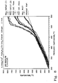
- the rolled structure was placed in the combustion apparatus discussed above in Example 3. Air was introduced into the catalyst at 800 SLPM and methane was introduced to produce a fuel/air (F/A) ratio of 0.045. The temperature of the mixture entering the catalyst was slowly increased. As may be seen from Figure 8, the catalyst began to catalyze the combustion reaction at about 475°C and was self-sustaining just about that point. The palladium self-limiting phenomenon may be observed in the upper portion of the wall outlet curve in Figure 8. The temperature curve flattened at about 780°C even though the preheat temperature continued to rise.
- Figure 9 shows steady state operation after catalyst stabilization.
- the preheat temperature was constant at 550°C.
- the catalyst operation was stable for the period shown.
Landscapes
- Chemical & Material Sciences (AREA)
- Engineering & Computer Science (AREA)
- Chemical Kinetics & Catalysis (AREA)
- Materials Engineering (AREA)
- Organic Chemistry (AREA)
- Environmental & Geological Engineering (AREA)
- Health & Medical Sciences (AREA)
- Analytical Chemistry (AREA)
- Biomedical Technology (AREA)
- General Chemical & Material Sciences (AREA)
- Oil, Petroleum & Natural Gas (AREA)
- Toxicology (AREA)
- Combustion & Propulsion (AREA)
- Mechanical Engineering (AREA)
- General Engineering & Computer Science (AREA)
- Catalysts (AREA)
- Gas Burners (AREA)
Abstract
Description
- This invention is a catalyst structure having integral heat exchange surfaces. This feature allows use of the structure in highly exothermic process, such as a combustion process, while maintaining the catalyst and the structure wall at a temperature below the adiabatic combustion temperature of the combustible gas mixture.
- US-A-4870824 refers to catalytic combustor units consisting of a series of generally parallel passages, some of which have a catalyst coating, and some of which do not. The material for supporting the is ceramic.
- With the advent of modern antipollution laws in the United States and around the world, significant and new methods of minimizing various pollutants are being investigated. The burning of fuel--be the fuel wood, coal, oil, or a natural gas--likely causes a majority of the pollution problems in existence today. Certain pollutants, such as SO2, which are created as the result of the presence of a contaminant in the fuel source may be removed either by treating the fuel to remove the contaminant or by treating the exhaust gas eventually produced. Other pollutants such as carbon monoxide, which are created as the result of imperfect combustion, may be removed by post-combustion oxidation or by improving the combustion process. The other principal pollutant, NOx (an equilibrium mixture mostly of NO, but also containing very minor amounts of NO2), may be dealt with either by controlling the combustion process to minimize NOx production or by later removal. Removal of NOx, once produced, is a difficult task because of its relative stability and its low concentrations in most exhaust gases. One solution used in automobiles is the use of carbon monoxide to reduce NOx to nitrogen while oxidizing the carbon monoxide to carbon dioxide. However, the need to react two pollutants also speaks to a conclusion that the initial combustion reaction was inefficient.
- It must be observed that unlike the situation with sulfur pollutants where the sulfur contaminant may be removed from the fuel, removal of nitrogen from the air fed to the combustion process is an impractical solution. Unlike the situation with carbon monoxide, improvement of the combustion reaction would likely increase the level of NOx produced due to the higher temperatures then involved.
- Nevertheless, the challenge to reduce NOx remains and several different methods have been suggested. The NOx abatement process chosen must not substantially conflict with the goal for which the combustion gas was created, i.e., the recovery of its heat value in a turbine, boiler, or furnace.
- Many recognize that a fruitful way to control NOx production is to limit the localized and bulk temperatures in the combustion zone to something less than 1800°C. See, for instance, U.S. Patent No. 4,731,989 to Furuya et al. at
column 1, lines 52-59 and U.S. Patent No. 4,088,135 to Hindin et al. atcolumn 12. - There are a number of ways of controlling the temperature, such as by dilution with excess air, by controlled oxidation using one or more catalysts, or by staged combustion using variously lean or rich fuel mixtures. Combinations of these methods are also known.
- One widely attempted method is the use of multistage catalytic combustion. Most of these processes utilize multi-section catalysts with metal or metal oxide catalysts on ceramic catalyst carriers. Typical of such disclosures are:

- It is, however, difficult to control the temperatures in these processes. Since the object of each of the processes is to produce a maximum amount of heat in a form which can be efficiently used in some later process, the combustion steps are essentially adiabatic. Consequently, a minor change in any of fuel rate, air rate, or operating processes in an early stage will cause significant changes in the latter stage temperatures. Very high temperatures place thermal strain on downstream catalytic elements.
- This list also makes clear that platinum group metals (including palladium) are considered useful in catalytic combustion processes. However, conventional catalytic combustion processes often mix the fuel and air and then pass this mixture over a catalyst with essentially complete combustion in the catalyst bed. This results in extremely high temperatures, typically 1100°C to 1500°C. For this reason, much of the catalyst development work is directed at catalysts and supports that can withstand those high temperatures and yet remain active. Some have relied on process control schemes in which the flow rate of an intermediate stream of air or fuel is introduced between catalyst stages and is controlled based upon bulk gas temperature. Furuya et al. (mentioned above) describes one approach in circumventing the problems associated with a high catalyst temperature through dilution of the fuel/air mixture with air fed to the catalyst so that the resulting mixture has an adiabatic combustion temperature of 900°C to 1000°C. This mixture is passed through the catalyst and partial or complete reaction gives a maximum catalyst temperature less than 1000°C and a gas temperature less than 1000°C. Additional fuel is added after the catalyst and homogeneous combustion of this mixture gives the required temperature (1200°C to 1500°C). This process, however, suffers from the need to add fuel at two stages and the requirements to mix this additional fuel with hot gases without obtaining a conventional high temperature diffusion flame and the associated production of NOx.
- We have found that a carefully constructed catalyst structure involving self-exchange of combustion heat into the flowing gas is an excellent way to control the temperature of the catalyst and the catalyst support. The metallic supports as we use them are much more flexible in their ability to control heat loads in a reaction and to provide long term chemical and physical stability. Use of such supports eliminates the need for the complicated air dilution procedures such as shown in Furuya et al.
- However, the use of metal catalyst supports for platinum group metals has been suggested in passing. See, for instance, U.S. Patent No. 4,088,435 (to Hindin et al.), "platinum group metals" at
column 4, lines 63 et seq., and "the support may be metallic or ceramic... " atcolumn 6, line 45. Conversely, the use of a platinum group alloy catalyst on a monolithic support as a combustion catalyst is suggested in U.S. Patent No. 4,287,856 (to Hindin et al.) atcolumn 1, line 65 et al. Other similar disclosures are found in the earlier U.S. Patent Nos. 3,966,391; 3,956,188; and 4,008,037 (all to Hindin et al.). Platinum on a steel ("Fecralloy") support as a combustion catalyst for low heating value gas is suggested in U.S. Patent No. 4,366,668 (to Madgavkar et al.). - Other disclosures of metals and metal supports used mainly for automotive catalytic converters include:
Country Document Assignee U.S. 3,920,583 Pugh U.S. 3,969,082 Cairns et al. U.S. 4,279,782 Chapman et al. U.S. 4,318,828 Chapman et al. U.S. 4,331,631 Chapman et al. U.S. 4,414,023 Aggen et al. U.S. 4,521,532 Cho U.S. 4,601,999 Retallick et al. U.S. 4,673,663 Maqnier U.S. 4,742,038 Matsumoto U.S. 4,752,599 Nakamura et al. U.S. 4,784,984 Yamanaka et al. Great Britain 1,528,455 Cairns et al. - As a group, these patents generally discuss ferritic catalyst supports upon which alumina is found as micro-crystals, coatings, whiskers, etc. Many disclose that platinum group metals are suitably placed on those supports as catalysts. None suggest the use of an integral heat exchanger in the catalyst support to aid in the catalyst operation.
- Two published Japanese Kokai teach the use of catalyst supports having integral heat exchange surfaces. They are Japanese Kokai 59-136,140 (published August 4, 1984) and Kokai 61-259,013 (published November 17, 1986). The earlier Kokai deals generally with a combustion process using a square-sectioned ceramic monolithic catalytic support in which alternating longitudinal channels (or alternating layers) are shown to have catalysts deposited therein. The monoliths disclosed there are ceramic and are consequently molded, not assembled.
- Similarly, the later Kokai discloses a process for the combustion of a fuel gas, in this case a blast furnace off-gas, using a catalyst structure such as that shown in the earlier Kokai or a structure of concentric cylinders in which alternating annular spaces in the support are coated with catalyst. Neither Kokai suggest the use of metal monoliths of any configuration in the processes.
- A disclosure very similar to the two Kokai is seen in U.S. Patent No. 4,870,824 to Young et al.
- In summary, although the literature suggests various unrelated portions of the inventive catalyst structure, none of these documents suggests metallic supports produced from a corrugated metal having catalytic material, particularly platinum group metals, deposited only on one side of the corrugated metal which are physically tough and have long term stability.
- This invention is both a catalyst structure suitable for use in a combustion process and a method of using that catalyst structure in a combustion process partially to burn a fuel/air mixture but maintain the catalyst and the catalyst support at a relatively low temperature.
- The catalyst structure desirably comprises a support and a combustion catalyst. The support is preferably metal. It may be corrugated and rolled or otherwise assembled in such a way that the combusting gas flows from end to end through the length of the corrugations. The catalyst is placed only on a portion of the corrugations in such a way that the catalyst is in heat exchange relationship to a substantially noncatalytic surface. The heat produced on the catalyst flows thorough the structure wall to the flowing gas at the opposite non-catalytic wall. The heat also flows to the adjacent combusted gas.
- The catalyst and its structure provide an exceptionally stable and temperature moderated structure having long life.
- Figures 1A, 1B, 1C, 2A, and 2B schematically depict various forms of the inventive catalyst structure.
- Figures 3A and 3B depict the operation of the structure.
- Figures 4A, 4B, 5, 6A, and 6B show various configurations of the inventive catalytic structure having catalytic material on a single side of the support.
- Figures 7 to 9 use temperature graphs showing operation of the inventive catalyst structure.
- This invention is a catalyst structure which is particularly useful in fuel combustion processes. The structure is preferably a platinum-group, metal-based catalyst on a metal monolith. The metal monolith is assembled from or fabricated from metallic materials having a catalytic surface and an adjunct non-catalytic surface. One side of the catalyst structure component has catalyst upon it and the other side of the catalyst structure component is essentially catalyst-free.
- The preferred supports for this catalytic zone are metallic. Metallic supports in the form of honeycombs, spiral rolls of corrugated sheet (which may be interspersed with flat separator sheets), columnar (or "handful of straws"), or other configurations having longitudinal channels or passageways permitting high space velocities with a minimal pressure drop are desirable in this service. They are malleable, may be mounted and attached to surrounding structures more readily, and offer lower flow resistance due to walls which are thinner than can be readily manufactured in ceramic supports. Another practical benefit attributable to metallic supports is the ability to survive thermal shock. Such thermal shocks occur in gas turbine operations when the turbine is started and stopped and, in particular, when the turbine must be rapidly shut down. In this latter case, the fuel is cut off or the turbine is "tripped" because the physical load on the turbine--e.g, a generator set--has been removed. Fuel to the turbine is immediately cut off to prevent overspeeding. The temperature in the combustion chambers, where the inventive process takes place, quickly drops from the temperature of combustion to the temperature of the compressed air. This drop could span more than 1000°C in less than one second.
- In any event, the catalyst is deposited, or otherwise placed, on at least a portion of the walls within the metal supports' channels or passageways in the amounts specified. By the phrase "at least a portion" is meant that each channel need not be coated along its entire length. In some instances catalyst placement along a portion of the length of the channel will be sufficient. Several types of support materials are satisfactory in this service: aluminum, aluminum-containing or aluminum-treated steels, certain stainless steels, any high temperature metal alloy (including nickel or cobalt alloys where a catalyst layer can be deposited on the metal surface), or other thermally resistant metal carbides or nitrides.
- The preferred materials are aluminum-containing steels such as those found in U.S. Patent Nos. 4,414,023 to Aggen et al., 4,331,631 to Chapman et al., and 3,969,082 to Cairns et al. These steels, as well as others sold by Kawasaki Steel Corporation (River Lite 20-5 SR), Vereinigte Deutchse Metallwerke AG (Alumchrom I RE), and Allegheny Ludlum Steel (Alfa-IV), contain sufficient dissolved aluminum so that, when oxidized, the aluminum forms alumina whiskers, crystals, or a layer on the steel's surface to provide a rough and chemically reactive surface for better adherence of the washcoat.
- The washcoat may be applied using an approach such as is described in the art, e.g., the application of gamma-alumina, zirconia, silica, or titania materials (preferably sols) or mixed sols of at least two oxides containing aluminum, silicon, titanium, zirconium, and additives such as barium, cerium, lanthanum, chromium, or a variety of other components. For better adhesion of the washcoat, a primer layer can be applied containing hydrous oxides such as a dilute suspension of pseudo-boehmite alumina as described in U.S. Patent 4,729,782 to Chapman et al. The primed surface may be coated with a gamma-alumina suspension, dried, and calcined to form a high surface area adherent oxide layer on the metal surface. Should alumina be chosen as a primer (or as some other portion of the catalyst support structure), it may be desirable to include a thermal stabilizer such as salts or oxides of lanthanum, barium, silicon, or one or more of the rare earths in the alumina. Alumina is not typically used in conjunction with the alumina because of a currently ill-defined propensity of the combination to deactivate.
- Most desirably, however is the use of a zirconia sol or suspension as the washcoat. Other refractory oxides, such as silica and titania, are also suitable. Most preferred for some platinum group metals, notably palladium, is a mixed zirconia/silica so where the two have been mixed prior to application to the support. Silica appears to allow the zirconia to maintain the catalyst's stability (e.g., its activity) for a long period of time.
- The washcoat may be applied in the same fashion one would apply paint to a surface, e.g., by spraying, direct application, dipping the support into the washcoat material, etc.
- Aluminum structures are also suitable for use in this invention and may be treated or coated in essentially the same manner. Aluminum alloys are somewhat more ductile and likely to deform or even to melt in the temperature operating envelope of the process. Consequently, they are less desirable supports but may be used if the temperature criteria can be met.
- Typical structures for this inventive catalyst are shown in the drawings. A metal sheet in the form of a long strip is corrugated in a cold rolling or other processing operation. This corrugated strip may be combined with a flat metal strip and rolled in a spiral to form a cylindrical catalyst structure through which gas can flow. The end view of this structure is shown in Figure 1A where the gas flow passages are straight channels. Rather than rolling, the corrugated and flat strips can be cut or folded and laid together to form structures such as seen in Figure 1B and Figure 1C. Alternatively, Chapman et al. in U.S. Patent No. 4,331,631 teaches the use of a herringbone corrugation pattern as shown in plan view in Figure 2A that, when folded or doubled and roiled into a spiral, will form an open corrugated structure without the use of a flat metal strip and will not nest as shown in Figure 2B. other similar metal structures may be formed from a variety of metal sheet structures and are useful in this invention.
- Critical to this invention is the application of a catalytic material only to one side of the metal forming the support structure as shown in Figure 3A where the washcoat and catalytic materials are applied as a thin layer to the metal foil surface using procedures well known in the art. For ferrous metals containing aluminum, the sheet may be heat treated in air to grow whiskers at the surface that increase adhesion of subsequent layers or provide increased surface area for direct application of a catalyst. A silica, alumina, zirconia, titania, or refractory metal oxide may then be applied by spraying onto the metal foil a solution, suspension, or other mixture of alumina, silica, zirconia, titania, or a refractory metal oxide, and drying and calcining to form a high surface area washcoat. The catalyst can then be applied, again such as by spraying a solution, suspension, or mixture of the catalytic components onto the washcoats on the metal strip.
- The catalytic material may also or alternatively be included in the washcoat material and coated onto the support thereby partially eliminating the separate catalyst inclusion step.
- Coating a metal foil with catalyst on only one side provides a catalytic surface with a very efficient heat exchange mechanism to the non-catalyzed opposite surface. For instance, in the structure in Figure 3B, the metal foil (30) is coated on one side with the oxide washcoat (32) and catalyst (34). This structure forms the walls of the channels formed by the corrugated and flat metal foils described in Figures 1A-1C and 2A-2B. The gas flowing past the catalytic surface (34) in Figure 3B results in reaction of the fuel and oxygen to generate heat. This heat is conducted into the gas stream (36) as well as through the metal oxide layer (32) and through the metal foil or sheet (30) to the gas stream (38) flowing on the opposite side of the metal wall. Since this surface has no catalytic coating, the gas is heated only by heat conducted from the catalytic coated surface on the opposite side of the metal substrate wall. The heat transfer coefficients for these two pathways, A and B, can be calculated using routine chemical engineering practice and correlations for a heat transfer between flowing gas and an adjacent solid surface according to, e.g., Whitaker, Fundamental Principles of Heat Tranfer, (1983), pp. 13-15. For heat generated at the washcoat surface near the washcoat/gas interface, the terms are:


- This integral heat exchange structure will have a substrate or wall temperature given by equation (1):

- As shown above, the metal sheets may be coated on one side with catalyst, and the other surface being non-catalytic, formed into rolled or layered structures (Figures 1A - 1C) to form long open channel structures offering low resistance to gas flow. Another alternative is formation of a corrugated metal strip (40) coated on one side with catalyst (42) can be combined with a separator strip (44) not having a catalytic coating to form the structure shown in Figure 4A.
- Alternatively as shown in Figure 4B, corrugated (46) and flat strips (48) both coated with catalyst on one side prior to assembly into a catalyst structure can be combined as shown. The structures form channels with catalytic walls (30 in Figure 4A and 52 in Figure 4B) and channels with non-catalytic walls (54 in Figure 3A and 56 in Figure 4B). These structures have the unique ability to limit the catalyst substrate temperature and outlet gas temperature.
- The corrugated (50) and flat sheets (54) coated on one side with catalyst can be arranged according to Figure 5 where the catalytic surface of each sheet faces a different channel so that all channels have a portion of their walls' catalyst coated and all walls have one surface coated with catalyst and the opposite surface non-catalytic. The Figure 5 structure will behave differently from the Figure 3A and Figure 3B structures. The walls of the Figure 5 structure form an integral heat exchange but, since all channels contain catalyst, there is then a potential for all of the fuel to be catalytically combusted. As combustion occurs at the catalyst surface, the temperature of the catalyst and support will rise and the heat will be conducted and dissipated in the gas flow on both the catalytic side and the non-catalytic side. This will help to limit the temperature of the catalyst substrate and will aid the palladium temperature limiting to maintain the wall temperature at 750°C to 800°C at one atm (1.013 x 10⁵ Pa) of air or about 930°C at ten atm (10.13 x 10⁵ Pa) of air. For sufficiently long catalysts or low gas velocities, a constant outlet gas temperature of 750°C to 800°C would be obtained for any fuel/air ratio with an adiabatic combustion temperature above approximately 800°C at one atm (1.013 x 10⁵ Pa) of air or about 930°C at ten atm (10.13 x 10⁵ Pa) of air.
- The structures shown in Figures 4A and 4B have equal gas flow through each of the catalytic channels and non-catalytic channels. The maximum gas temperature rise with these structures will be that produced by 50% combustion of the inlet fuel.
- The structures shown in Figures 4A and 4B may be modified to control the fraction of fuel and oxygen reacted by varying the fraction of the fuel and oxygen mixture that passes through catalytic and non-catalytic channels. In general, the larger the area coated with catalyst in heat exchange with the non-coated areas, the more closely the bulk temperature of the gas will approach the adiabatic combustion temperature of the gas or the self-limiting temperature of the catalyst if the catalyst comprises platinum. Figure 6A shows a structure where the corrugated foil has a structure with alternating narrow (60) and broad (62) corrugations. Coating this corrugated foil on one side results in a large catalytic channel (64) and a small non-catalytic channel (66). In this structure approximately 80% of the gas flow would pass through catalytic channels and 20% through the non-catalytic channels. The maximum outlet gas temperature would be about 80% of the temperature rise expected if the gas went to its adiabatic combustion temperature. Conversely, coating the other side of the foil only (Figure 6B) results in a structure with only 20% of the gas flow through catalytic channels (68) and a maximum outlet gas temperature increase of 20% of the adiabatic combustion temperature rise. Proper design of the corrugation shape and size can achieve any level of conversion from 5% to 95% while incorporating integral heat exchange. The ratio of the areas of the catalytically active channels to the catalytically inactive channels for these channels may be from 1:20 to 20:1. The ratio of these areas will approximate the ratio of the gas flows as shown in this equation. The maximum outlet gas temperature can be calculated by
equation 2 below:
- To illustrate the operation of this integral heat exchange zone, assume that a partially oxidized gas from the first catalytic zone flows into the Figure 4B structure in which the gas flow through the catalytic channels is 50% of the total flow.
- Approximately half of the gas flow will pass through channels with catalytic walls (52) and half will flow through channels with non-catalytic walls (56). Fuel combustion will occur at the catalytic surface and heat will be dissipated to the gas flowing in both the catalytic and non-catalytic channels. If the entering gas is 500°C and the fuel/air ratio corresponds to a theoretical adiabatic combustion temperature of 1300°C, then combustion of the fuel in the catalytic channels will cause the temperature of all of the flowing gases to rise. The heat is dissipated into gas flowing in both the catalytic and non-catalytic channels. The calculated L-IHE wall temperature is:


- The situation is different at ten atms (10.13 x 10⁵ Pa) of air pressure. The palladium self-limiting temperature is about 930°C. The wall will be limited to 900°C by the L-IHE structure. In this case, the L-IHE structure is limiting the wall and gas temperature.
- The catalyst structure may be sized to maintain flow velocity to reach a bulk outlet temperature of no more than 800°C, preferably in the range of 600°C to and most preferably between 700°C and 800°C. The catalyst can incorporate a non-catalytic diffusion barrier layer on the catalytic material such as that described by Attorney Docket No. PA-0004.
- The catalytic metal content of the composite is typically quite small, e.g., from 0.01% to about 15% by weight, and preferably from 0.01% to about 10% by weight. Although many oxidation catalysts are suitable in this application, Group VIII noble metals or platinum group metals (palladium, ruthenium, rhodium, platinum, osmium, and iridium) are preferred. More preferred are palladium (because of its ability to self-limit combustion temperatures) and platinum (because of its lower expense and excellent activity). The metals may be used singly or in mixtures. We have found that mixture of, for example, palladium and platinum, produce a catalyst having the temperature limiting capabilities of palladium, although at a different limiting temperature, and the mixture is less susceptible to deactivation by reaction with impurities in the fuel or by reaction with the catalyst support.
- The platinum group metals may be incorporated onto the support in a variety of different methods using noble metal complexes, compounds, or dispersions of the metal. The compounds or complexes may be water or hydrocarbon soluble. The metal may be precipitated from solution. The liquid carrier generally needs only to be removable from the catalyst carrier by volatilization or decomposition while leaving the metal in a dispersed form on the support.
- Suitable platinum group metal compounds are, for example, chloroplatinic acid, potassium platinum chloride, ammonium platinum thiocyanate, platinum tetrammine hydroxide, platinum group metal chlorides, oxides, sulfides, and nitrates, platinum tetrammine chloride, platinum ammonium nitrite, palladium tetrammine chloride, palladium ammonium nitrite, rhodium chloride, and hexammine iridium chloride. If a mixture of metals is desired, they may be in water soluble form, for example, as amine hydroxides or they may be present in such forms as chloroplatinic acid and palladium nitrate when used in preparing the catalyst of the present invention. The platinum group metal may be present in the catalyst composition in elemental or combined forms, e.g., as an oxide or sulfide. During subsequent treatment such by calcining or upon use, essentially all of the platinum group metal is converted to the elemental form.
- In addition to the Group VIII noble metal catalyst adjuncts, catalyst adjuncts of a Group IB metal may be desirable in certain circumstances to lower the initiation of the self-limiting temperature feature of the palladium form of the catalyst. Preferred metals are silver and gold, especially silver. This metal (or metals) may also be added by inclusion in the liquid carrier containing the platinum group metal, a complex, compound, or metallic dispersion of the catalyst adjunct. For instance, silver chloride or silver tetrammine salts may be added to the palladium solution or suspension. The catalyst adjunct metal may alternatively be added in a separate step after or before the palladium is deposited on the support although the mixing of the adjunct with the palladium on the support appears to be less complete if the adjunct is added separately. The adjunct should be added in an amount up to an equilibrium amount.
- This catalyst structure should be made in such a size and configuration that the average linear velocity of the gas through the longitudinal channels in the catalyst structure is greater than about .02 m/second throughout the catalytic structure and no more than about 40 m/second. The lower limit is larger than the flame front speed for methane in air at 350°C and the upper limit is a practical one for the type of supports currently commercially available. These average velocities may be somewhat different for fuels other than methane. Slower burning fuels may permit use of a lower minimum and maximum space velocity.
- These examples show the use of the inventive catalyst structure.
- This example shows the preparation of a single sided metal monolith structure using a platinum catalyst.
- A mixed oxide containing approximately 5% SiO2 in gamma-alumina was calcined at 1050°C in air to give a powder with a specific surface area of 190 m2/gm. A polymer lined ball mill was loaded with 125 g of the SiO2/Al2O3 powder, 220 ml water, 10 ml of concentrated nitric acid (70% HNO3), and cylindrical alumina grinding media. This mixture was milled for eight hours to produce a colloidal sol.
- An Fe/Cr/Al alloy foil strip was corrugated in a herringbone pattern. The strip was then oxidized at 900 °C in air to form a rough oxide coated surface. The SiO2/Al2O3 sol was sprayed onto a single sided foil using an air atomizer sprayer and the coated foil dried and calcined. Subsequently, the coated foil was sprayed with a solution containing platinum in a concentration of 0.042 g platinum/ml. This solution was prepared from Pd(HN3)2(NO2)2 dissolved in nitric acid. Again, the foil was dried and calcined. The final foil contained approximately 2.9 m2/gm of SiO2/Al2O3 and 0.6 m2/gm of SiO2/Al2O3 of platinum.
- This example is a comparative example and shows the production of a double sided metal monolith structure using a platinum catalyst.
- A second catalyst was prepared in a similar fashion to that shown in Example 1 except that both sides of the foil were coated with SiO2/Al2O3 and platinum. The final composition of this catalyst contained approximately 1.7 gm/cm3 of SiO2/Al2O3 on each side and 0.3 m2/gm of platinum on each side.
- This example compares the operation of the catalysts of Examples 1 and 2 in a combustion process and demonstrates relatively longer term stability with the single sided catalyst using integral heat exchange.
- The Example 1 and 2 catalysts were rolled into a tight spiral of about two inches diameter and placed in a two inch I.D. insulated section in a combustion reactor. Air at 800 standard liters/minute (SLPM) was passed through an electric heater, a static gas mixer, and through the catalyst. Natural gas (21 SLPM) was introduced into the air stream just upstream of the gas mixer. Gas temperatures were measured before and after the catalyst with ceramic covered thermocouples suspended in the gas stream. The temperature of the incoming air/natural gas mixture or "preheat" was increased in each case to 750°C and the catalyst performance monitored. The results are shown in Figure 7.
- The single sided catalyst shows more stable operation in that the gas outlet temperature for the single sided catalyst is constant. The gas outlet temperature for the double sided catalyst is declining even in the short twelve hour screening test shown in Figure 7.
- This example shows the production of a single sided metallic structure using a mixed oxide washcoat and a palladium catalyst.
- A ZrO2/SiO2 powder was prepared by first mixing 20.8 g of tetraorthosilicate with 4.57
cc 2 mM nitric acid and 12.7 g of ethanol. The mixture was added to 100 g of a zirconia powder having a specific surface area of 100 m2/gm. The resulting solid was aged in a sealed glass container for about a day and dried. One portion was calcined at 400 °C and another was calcined at 1000°C. - A so was prepared by mixing 152 g of the ZrO2/SiO2 powder calcined at 1000°C and 15.2 g of the ZrO2/SiO2 powder calcined at 400°C with 3.93 g 982 H2SO4 and 310 cc of distilled water. This mixture was milled using ZrO2 grinding media for eight hours. Colloidal silica (11.9 g) was added to the ball mill and the milling was then continued for 30 minutes.
- A mixture of palladium salts and ZrO2/SiO2 was then produced. About 100 g of ZrO2/SiO2 sol was mixed with 84 ml of 0.083 g palladium/ml solution prepared from Pd(HN3)2(NO2)2 dissolved in nitric acid. The pH of the solution was adjusted to 9.0, 1.26 g of N2H4 was added with stirring, and the pH was again adjusted to 3.0. An amount (5.4 g) of a 34% colloidal silica sol was added to the mixture.
- The final sol was then sprayed onto one side of a corrugated 2 inch wide steel (Camet) foil strip. The foil had been heated in air to produce a rough oxidic surface. The sprayed foil was wound into a tight spiral coil having about 320 cells per square inch. The rolled structure was dried and then calcined at 950°C.
- The rolled structure was placed in the combustion apparatus discussed above in Example 3. Air was introduced into the catalyst at 800 SLPM and methane was introduced to produce a fuel/air (F/A) ratio of 0.045. The temperature of the mixture entering the catalyst was slowly increased. As may be seen from Figure 8, the catalyst began to catalyze the combustion reaction at about 475°C and was self-sustaining just about that point. The palladium self-limiting phenomenon may be observed in the upper portion of the wall outlet curve in Figure 8. The temperature curve flattened at about 780°C even though the preheat temperature continued to rise.
- Figure 9 shows steady state operation after catalyst stabilization. The preheat temperature was constant at 550°C. The catalyst operation was stable for the period shown.
- The invention has been disclosed by direct description. Others having ordinary skill in this art will recognize equivalent variations of the claimed invention which will be within the scope of the appended claims.
Claims (40)
- A catalyst structure comprising a metallic catalyst support having a multitude of passageways adapted for the passage of combustible gas, the structure having interior surfaces where at least a portion but not all of the interior surfaces are coated with a catalytic material suitable for oxidizing the combustible gas, the interior surfaces coated with catalytic material being in heat exchange relationship with interior surfaces not coated with a catalytic material.
- The catalyst structure of claim 1 where some passageways contain catalytic material.
- The catalyst structure of claim 1 where all of the passageways contain catalytic material.
- The catalyst structure of claims 1, 2 or 3 wherein the metallic catalyst support comprises aluminium, a high temperature metal alloy, stainless steel, or a ferrous alloy containing aluminium.
- The catalyst structure of claim 4 wherein the metallic catalyst support comprises a ferrous alloy containing aluminium.
- The catalyst structure of claim 5 wherein the metallic catalyst support additionally comprises a washcoat of zirconia, titania, alumina, silica, or refractory metal oxide on at least a portion of the support.
- The catalyst structure of claim 6 where the washcoat comprises alumina.
- The catalyst structure of claim 6 where the washcoat comprises zirconia.
- The catalyst structure of claim 6 where the washcoat comprises a mixture of at least two of zirconia, titania, alumina and silica.
- The catalyst structure of claim 9 where the washcoat comprises a mixture of zirconia and silica.
- The catalyst structure of claim 5 or 6 where the catalytic material is one or more platinum group metals on the washcoat.
- The catalyst structure of claim 6 or 7 where the catalytic material comprises platinum.
- The catalyst structure of claim 6, 8 or 10 where the catalytic material comprises palladium.
- The catalyst structure of claim 6 where the catalytic material comprises palladium and platinum.
- The catalyst structure of claim 5 where the passageways containing catalyst are relatively larger than the passageways not containing catalyst.
- The catalyst structure of claim 5 where the passageways containing catalyst are relatively smaller than the passageways not containing catalyst.
- The catalyst structure of claim 5 where the passageways containing catalyst are relatively of equal size to the passageways not containing catalyst.
- The catalyst structure of claim 15, 16 or 17 where the ratio of the open area of the passageways containing catalyst to the open area of the passageways not containing catalyst is between 1:20 and 20:1.
- The catalyst structure of claim 5 where the metallic catalyst support comprises a spiral roll of corrugated sheet.
- The catalyst structure of claim 5 where the catalyst support is a rolled spiral comprising corrugated sheet and a spacer sheet.
- The catalyst structure of claim 5 where the metallic catalyst support is in a herringbone pattern.
- The catalyst structure of claim 5 where the metallic catalyst support is assembled comprising generally parallel alternating layers of corrugated and flat spacer sheets.
Applications Claiming Priority (3)
| Application Number | Priority Date | Filing Date | Title |
|---|---|---|---|
| US617974 | 1990-11-26 | ||
| US07/617,974 US5250489A (en) | 1990-11-26 | 1990-11-26 | Catalyst structure having integral heat exchange |
| PCT/US1991/008910 WO1992009365A1 (en) | 1990-11-26 | 1991-11-26 | A catalyst structure having integral heat exchange (ii) |
Publications (3)
| Publication Number | Publication Date |
|---|---|
| EP0559808A1 EP0559808A1 (en) | 1993-09-15 |
| EP0559808A4 EP0559808A4 (en) | 1993-10-27 |
| EP0559808B1 true EP0559808B1 (en) | 1997-01-29 |
Family
ID=24475821
Family Applications (1)
| Application Number | Title | Priority Date | Filing Date |
|---|---|---|---|
| EP92902357A Expired - Lifetime EP0559808B1 (en) | 1990-11-26 | 1991-11-26 | A catalyst structure having integral heat exchange (ii) |
Country Status (13)
| Country | Link |
|---|---|
| US (1) | US5250489A (en) |
| EP (1) | EP0559808B1 (en) |
| JP (1) | JPH06506139A (en) |
| KR (1) | KR100234887B1 (en) |
| CN (1) | CN1064420A (en) |
| AT (1) | ATE148374T1 (en) |
| AU (1) | AU9118291A (en) |
| CA (1) | CA2096950C (en) |
| DE (1) | DE69124528T2 (en) |
| ES (1) | ES2098492T3 (en) |
| RU (1) | RU2065766C1 (en) |
| TW (1) | TW206162B (en) |
| WO (1) | WO1992009365A1 (en) |
Cited By (1)
| Publication number | Priority date | Publication date | Assignee | Title |
|---|---|---|---|---|
| US6174159B1 (en) | 1999-03-18 | 2001-01-16 | Precision Combustion, Inc. | Method and apparatus for a catalytic firebox reactor |
Families Citing this family (110)
| Publication number | Priority date | Publication date | Assignee | Title |
|---|---|---|---|---|
| US5474441A (en) * | 1989-08-22 | 1995-12-12 | Engelhard Corporation | Catalyst configuration for catalytic combustion systems |
| US5326253A (en) * | 1990-11-26 | 1994-07-05 | Catalytica, Inc. | Partial combustion process and a catalyst structure for use in the process |
| US5634784A (en) * | 1991-01-09 | 1997-06-03 | Precision Combustion, Inc. | Catalytic method |
| US5328359A (en) * | 1992-05-19 | 1994-07-12 | W. R. Grace & Co.-Conn. | Ignition stage for a high temperature combustor |
| US5281359A (en) * | 1992-08-31 | 1994-01-25 | Hoechst Celanese Corporation | Polymeric carbonylation catalyst system |
| JP3430422B2 (en) * | 1992-12-14 | 2003-07-28 | 財団法人石油産業活性化センター | Catalyst for catalytic reduction of nitrogen oxides |
| US5714432A (en) * | 1992-12-28 | 1998-02-03 | Kabushiki Kaisha Riken | Exhaust gas cleaner comprising supported silver or silver oxide particles |
| AU6138394A (en) * | 1993-03-01 | 1994-09-26 | Engelhard Corporation | Improved catalytic combustion system including a separator body |
| WO1994020789A1 (en) * | 1993-03-04 | 1994-09-15 | Engelhard Corporation | Improved substrate configuration for catalytic combustion system |
| US5461864A (en) * | 1993-12-10 | 1995-10-31 | Catalytica, Inc. | Cooled support structure for a catalyst |
| TW299345B (en) * | 1994-02-18 | 1997-03-01 | Westinghouse Electric Corp | |
| US5422331A (en) * | 1994-02-25 | 1995-06-06 | Engelhard Corporation | Layered catalyst composition |
| US5512250A (en) * | 1994-03-02 | 1996-04-30 | Catalytica, Inc. | Catalyst structure employing integral heat exchange |
| US6207116B1 (en) * | 1994-08-04 | 2001-03-27 | Enklaven Ab | Catalytic purification device |
| US5512324A (en) * | 1994-11-14 | 1996-04-30 | General Motors Corporation | Metal substrate with insulative coating thereon and method of making the same |
| US6116014A (en) * | 1995-06-05 | 2000-09-12 | Catalytica, Inc. | Support structure for a catalyst in a combustion reaction chamber |
| DE19524158A1 (en) * | 1995-07-03 | 1997-01-09 | Degussa | Process for the production of hydrocyanic acid |
| US6109018A (en) * | 1996-07-26 | 2000-08-29 | Catalytica, Inc. | Electrically-heated combustion catalyst structure and method for start-up of a gas turbine using same |
| DE19653991A1 (en) | 1996-12-21 | 1998-06-25 | Degussa | Reactor for carrying out endothermic catalytic reactions |
| US6015285A (en) * | 1998-01-30 | 2000-01-18 | Gas Research Institute | Catalytic combustion process |
| WO1999055459A1 (en) * | 1998-04-28 | 1999-11-04 | Engelhard Corporation | Monolithic catalysts and related process for manufacture |
| US6217832B1 (en) | 1998-04-30 | 2001-04-17 | Catalytica, Inc. | Support structures for a catalyst |
| AU4126099A (en) * | 1998-06-09 | 1999-12-30 | Vladimir Zorievich Iakhnine | Method for adaptive control of exothermal catalytic reactors and reactors therefor |
| US6013599A (en) | 1998-07-15 | 2000-01-11 | Redem Corporation | Self-regenerating diesel exhaust particulate filter and material |
| US6095793A (en) * | 1998-09-18 | 2000-08-01 | Woodward Governor Company | Dynamic control system and method for catalytic combustion process and gas turbine engine utilizing same |
| DE19914814C1 (en) * | 1999-03-31 | 2000-12-14 | Siemens Ag | Recombination device and method for the catalytic recombination of hydrogen and / or carbon monoxide with oxygen in a gas mixture |
| DE19925390C1 (en) * | 1999-06-02 | 2000-08-03 | Emitec Emissionstechnologie | Honeycomb body used as catalyst carrier for purifying I.C. engine and diesel exhaust gas has two coated or wound sheet metal layers |
| AU5758000A (en) * | 1999-06-22 | 2001-01-09 | Daniel Preston | Improved burners and process of making |
| US6334769B1 (en) | 1999-07-27 | 2002-01-01 | United Technologies Corporation | Catalytic combustor and method of operating same |
| BR0013344A (en) * | 1999-08-17 | 2002-06-04 | Battelle Memorial Institute | Catalyst structure and fischer-tropsch synthesis process |
| RU2177363C2 (en) * | 2000-03-17 | 2001-12-27 | Рахманов Геннадий Жанович | Catalyst converter |
| US6595003B2 (en) | 2000-08-31 | 2003-07-22 | Ralph A. Dalla Betta | Process and apparatus for control of NOx in catalytic combustion systems |
| US6415608B1 (en) * | 2000-09-26 | 2002-07-09 | Siemens Westinghouse Power Corporation | Piloted rich-catalytic lean-burn hybrid combustor |
| US6718772B2 (en) | 2000-10-27 | 2004-04-13 | Catalytica Energy Systems, Inc. | Method of thermal NOx reduction in catalytic combustion systems |
| US7121097B2 (en) | 2001-01-16 | 2006-10-17 | Catalytica Energy Systems, Inc. | Control strategy for flexible catalytic combustion system |
| EP1336068B1 (en) | 2000-11-13 | 2006-09-13 | Catalytica Energy Systems, Inc. | Thermally tolerant support structure for a catalytic combustion catalyst |
| US6698412B2 (en) | 2001-01-08 | 2004-03-02 | Catalytica Energy Systems, Inc. | Catalyst placement in combustion cylinder for reduction on NOx and particulate soot |
| SE523018C2 (en) * | 2001-02-09 | 2004-03-23 | Enklaven Ab | Muffler and use of said muffler in an exhaust system for an internal combustion engine |
| US6716400B2 (en) * | 2001-03-09 | 2004-04-06 | Honda Giken Kogyo Kabushiki Kaisha | Ignition system for a fuel cell hydrogen generator |
| EP1255079A1 (en) * | 2001-04-30 | 2002-11-06 | ALSTOM (Switzerland) Ltd | Catalyst |
| GB0116894D0 (en) * | 2001-07-11 | 2001-09-05 | Accentus Plc | Catalytic reactor |
| US6796129B2 (en) | 2001-08-29 | 2004-09-28 | Catalytica Energy Systems, Inc. | Design and control strategy for catalytic combustion system with a wide operating range |
| US7326669B2 (en) * | 2001-09-20 | 2008-02-05 | Honda Motor Co., Ltd. | Substrate having catalyst compositions on surfaces of opposite sides |
| US6588213B2 (en) | 2001-09-27 | 2003-07-08 | Siemens Westinghouse Power Corporation | Cross flow cooled catalytic reactor for a gas turbine |
| US6948928B2 (en) * | 2001-10-18 | 2005-09-27 | Catacel Corporation | Catalytic combustor for a gas turbine |
| US7082753B2 (en) * | 2001-12-03 | 2006-08-01 | Catalytica Energy Systems, Inc. | System and methods for improved emission control of internal combustion engines using pulsed fuel flow |
| US7165393B2 (en) * | 2001-12-03 | 2007-01-23 | Catalytica Energy Systems, Inc. | System and methods for improved emission control of internal combustion engines |
| US7250151B2 (en) * | 2002-08-15 | 2007-07-31 | Velocys | Methods of conducting simultaneous endothermic and exothermic reactions |
| US7014835B2 (en) | 2002-08-15 | 2006-03-21 | Velocys, Inc. | Multi-stream microchannel device |
| US6810670B2 (en) | 2002-09-17 | 2004-11-02 | Siemens Westinghouse Power Corporation | Corrugated catalyst support structure for use within a catalytic reactor |
| WO2004046514A1 (en) * | 2002-11-15 | 2004-06-03 | Catalytica Energy Systems, Inc. | Devices and methods for reduction of nox emissions from lean burn engines |
| US20040255588A1 (en) * | 2002-12-11 | 2004-12-23 | Kare Lundberg | Catalytic preburner and associated methods of operation |
| JP2006515659A (en) * | 2003-01-17 | 2006-06-01 | カタリティカ エナジー システムズ, インコーポレイテッド | Dynamic control system and method for a multiple combustion chamber catalytic gas turbine engine |
| US20040141893A1 (en) * | 2003-01-21 | 2004-07-22 | Martin Jerry L. | Chemical reactor with enhanced heat exchange |
| US7220699B2 (en) * | 2003-03-31 | 2007-05-22 | Intelligent Energy, Inc. | Catalyst incorporation in a microreactor |
| US6920920B2 (en) * | 2003-04-16 | 2005-07-26 | Catacel Corporation | Heat exchanger |
| EP1664696A2 (en) * | 2003-09-05 | 2006-06-07 | Catalytica Energy Systems, Inc. | Catalyst module overheating detection and methods of response |
| US7278265B2 (en) * | 2003-09-26 | 2007-10-09 | Siemens Power Generation, Inc. | Catalytic combustors |
| RU2234978C1 (en) * | 2003-10-13 | 2004-08-27 | Институт катализа им. Г.К. Борескова СО РАН | Metal-based catalyst carrier (options) and a method for preparation thereof (options) |
| US7086235B2 (en) * | 2003-11-26 | 2006-08-08 | United Technologies Corporation | Cascade ignition of catalytic combustors |
| US8062623B2 (en) * | 2004-10-15 | 2011-11-22 | Velocys | Stable, catalyzed, high temperature combustion in microchannel, integrated combustion reactors |
| US7240483B2 (en) * | 2004-08-02 | 2007-07-10 | Eaton Corporation | Pre-combustors for internal combustion engines and systems and methods therefor |
| US8648006B2 (en) * | 2005-10-13 | 2014-02-11 | Velocys, Inc. | Electroless plating in microchannels |
| US8671658B2 (en) | 2007-10-23 | 2014-03-18 | Ener-Core Power, Inc. | Oxidizing fuel |
| US8393160B2 (en) | 2007-10-23 | 2013-03-12 | Flex Power Generation, Inc. | Managing leaks in a gas turbine system |
| US20090227195A1 (en) * | 2008-03-07 | 2009-09-10 | Basf Catalysts Llc | Systems and Methods for Treating Aircraft Cabin Air |
| US8701413B2 (en) | 2008-12-08 | 2014-04-22 | Ener-Core Power, Inc. | Oxidizing fuel in multiple operating modes |
| US20100158775A1 (en) | 2008-12-18 | 2010-06-24 | Basf Catalysts Llc | Catalyst Systems and Methods for Treating Aircraft Cabin Air |
| US8357427B2 (en) * | 2009-02-12 | 2013-01-22 | International Engine Intellectual Property Company, Llc | Preparation method for a partially coated monolith |
| US8920759B2 (en) * | 2009-03-02 | 2014-12-30 | GM Global Technology Operations LLC | Method and apparatus for reducing NOx emissions from a lean burning hydrocarbon fueled power source |
| US8621869B2 (en) | 2009-05-01 | 2014-01-07 | Ener-Core Power, Inc. | Heating a reaction chamber |
| US8889079B2 (en) * | 2010-01-13 | 2014-11-18 | Efb, Inc. | Apparatus for removal of particles and VOC from an airstream |
| KR101973576B1 (en) | 2010-03-02 | 2019-04-29 | 벨로시스, 인코포레이티드 | Welded, laminated apparatus, methods of making, and methods of using the apparatus |
| EP2547888A4 (en) | 2010-03-15 | 2016-03-16 | Ener Core Power Inc | Processing fuel and water |
| US9057028B2 (en) | 2011-05-25 | 2015-06-16 | Ener-Core Power, Inc. | Gasifier power plant and management of wastes |
| US9279364B2 (en) | 2011-11-04 | 2016-03-08 | Ener-Core Power, Inc. | Multi-combustor turbine |
| US9273606B2 (en) | 2011-11-04 | 2016-03-01 | Ener-Core Power, Inc. | Controls for multi-combustor turbine |
| US8844473B2 (en) | 2012-03-09 | 2014-09-30 | Ener-Core Power, Inc. | Gradual oxidation with reciprocating engine |
| US9206980B2 (en) | 2012-03-09 | 2015-12-08 | Ener-Core Power, Inc. | Gradual oxidation and autoignition temperature controls |
| US9267432B2 (en) | 2012-03-09 | 2016-02-23 | Ener-Core Power, Inc. | Staged gradual oxidation |
| US9534780B2 (en) | 2012-03-09 | 2017-01-03 | Ener-Core Power, Inc. | Hybrid gradual oxidation |
| US9359948B2 (en) | 2012-03-09 | 2016-06-07 | Ener-Core Power, Inc. | Gradual oxidation with heat control |
| US8807989B2 (en) | 2012-03-09 | 2014-08-19 | Ener-Core Power, Inc. | Staged gradual oxidation |
| US9381484B2 (en) | 2012-03-09 | 2016-07-05 | Ener-Core Power, Inc. | Gradual oxidation with adiabatic temperature above flameout temperature |
| US9234660B2 (en) | 2012-03-09 | 2016-01-12 | Ener-Core Power, Inc. | Gradual oxidation with heat transfer |
| US8926917B2 (en) | 2012-03-09 | 2015-01-06 | Ener-Core Power, Inc. | Gradual oxidation with adiabatic temperature above flameout temperature |
| US9567903B2 (en) | 2012-03-09 | 2017-02-14 | Ener-Core Power, Inc. | Gradual oxidation with heat transfer |
| US8671917B2 (en) | 2012-03-09 | 2014-03-18 | Ener-Core Power, Inc. | Gradual oxidation with reciprocating engine |
| US9726374B2 (en) | 2012-03-09 | 2017-08-08 | Ener-Core Power, Inc. | Gradual oxidation with flue gas |
| US9359947B2 (en) | 2012-03-09 | 2016-06-07 | Ener-Core Power, Inc. | Gradual oxidation with heat control |
| US9371993B2 (en) | 2012-03-09 | 2016-06-21 | Ener-Core Power, Inc. | Gradual oxidation below flameout temperature |
| US8980193B2 (en) | 2012-03-09 | 2015-03-17 | Ener-Core Power, Inc. | Gradual oxidation and multiple flow paths |
| US9353946B2 (en) | 2012-03-09 | 2016-05-31 | Ener-Core Power, Inc. | Gradual oxidation with heat transfer |
| US9017618B2 (en) | 2012-03-09 | 2015-04-28 | Ener-Core Power, Inc. | Gradual oxidation with heat exchange media |
| US9328916B2 (en) | 2012-03-09 | 2016-05-03 | Ener-Core Power, Inc. | Gradual oxidation with heat control |
| US9347664B2 (en) | 2012-03-09 | 2016-05-24 | Ener-Core Power, Inc. | Gradual oxidation with heat control |
| US9328660B2 (en) | 2012-03-09 | 2016-05-03 | Ener-Core Power, Inc. | Gradual oxidation and multiple flow paths |
| US8980192B2 (en) | 2012-03-09 | 2015-03-17 | Ener-Core Power, Inc. | Gradual oxidation below flameout temperature |
| US9273608B2 (en) | 2012-03-09 | 2016-03-01 | Ener-Core Power, Inc. | Gradual oxidation and autoignition temperature controls |
| CN103480369B (en) * | 2012-06-13 | 2015-05-20 | 中国石油天然气股份有限公司 | A kind of platinum nanocomposite catalyst and its preparation and application |
| RU2514382C1 (en) * | 2012-10-09 | 2014-04-27 | Гребнев Вениамин Владимирович | Production of ice rhenium- and ruthenium-bearing catalytic neutralisers |
| KR102468548B1 (en) * | 2014-07-29 | 2022-11-18 | 코르메텍, 인코포레이티드 | Catalyst modules and applications thereof |
| CN107401742A (en) * | 2016-05-18 | 2017-11-28 | 浙江天泽环境科技股份有限公司 | A kind of double-deck more micropore catalytic burners |
| RU2635111C1 (en) * | 2016-09-16 | 2017-11-09 | Публичное акционерное общество "Нефтяная компания "Роснефть" | Catalyst of oxidating combustible gases, method of its production and method of synthesis of iridium-containing connection-predecessor |
| CN111867724B (en) | 2018-03-28 | 2023-04-28 | 三井金属矿业株式会社 | Catalyst for purifying exhaust gas |
| WO2020065956A1 (en) * | 2018-09-28 | 2020-04-02 | 日立化成株式会社 | Steam reforming method, steam reforming member, and steam reformer |
| CN112197263B (en) * | 2019-07-08 | 2026-04-17 | 芜湖美的厨卫电器制造有限公司 | Combustion heat exchange components and gas combustion equipment having them |
| CN111250010B (en) * | 2020-01-20 | 2021-09-24 | 山东大学 | Catalyst carrier and micro-channel continuous flow reactor |
| JP2023135093A (en) * | 2022-03-15 | 2023-09-28 | トヨタ自動車株式会社 | Method for manufacturing exhaust gas purification catalyst |
| CN122055204A (en) * | 2023-10-17 | 2026-05-15 | 巴斯夫公司 | Metal substrate for VOC emission control |
Family Cites Families (88)
| Publication number | Priority date | Publication date | Assignee | Title |
|---|---|---|---|---|
| GB1469527A (en) * | 1973-03-30 | 1977-04-06 | Atomic Energy Authority Uk | Manufacture of catalysts |
| US4008037A (en) * | 1973-12-10 | 1977-02-15 | Engelhard Minerals & Chemicals Corporation | Compositions and methods for high temperature stable catalysts |
| US3966391A (en) * | 1973-12-10 | 1976-06-29 | Engelhard Minerals & Chemicals Corporation | Method of combustion using high temperature stable catalysts |
| US3956188A (en) * | 1973-12-10 | 1976-05-11 | Engelhard Minerals & Chemicals Corporation | Compositions and methods for high temperature stable catalysts |
| US3966790A (en) * | 1973-12-10 | 1976-06-29 | Engelhard Minerals & Chemicals Corporation | Compositions and methods for high temperature stable catalysts |
| GB1471138A (en) * | 1974-05-06 | 1977-04-21 | Atomic Energy Authority Uk | Supports for catalyst materials |
| US3970435A (en) * | 1975-03-27 | 1976-07-20 | Midland-Ross Corporation | Apparatus and method for methanation |
| US4019969A (en) * | 1975-11-17 | 1977-04-26 | Instytut Nawozow Sztucznych | Method of manufacturing catalytic tubes with wall-supported catalyst, particularly for steam reforming of hydrocarbons and methanation |
| GB1528455A (en) * | 1976-01-27 | 1978-10-11 | Atomic Energy Authority Uk | Catalyst preparation by deposition |
| US4101287A (en) * | 1977-01-21 | 1978-07-18 | Exxon Research & Engineering Co. | Combined heat exchanger reactor |
| SE7802205L (en) * | 1977-03-04 | 1978-09-05 | Johnson Matthey Co Ltd | IMPROVEMENTS IN AND REGARDING CATALYSIS |
| CA1146362A (en) * | 1978-05-08 | 1983-05-17 | Bernard E. Enga | Engines |
| US4331631A (en) * | 1979-11-28 | 1982-05-25 | General Motors Corporation | Enhanced oxide whisker growth on peeled Al-containing stainless steel foil |
| US4279782A (en) * | 1980-03-31 | 1981-07-21 | General Motors Corporation | Application of an alumina coating to oxide whisker-covered surface on Al-containing stainless steel foil |
| US4318828A (en) * | 1980-08-15 | 1982-03-09 | General Motors Corporation | Enhanced oxide whisker growth on cold-rolled aluminum-containing stainless steel foil |
| US4603547A (en) * | 1980-10-10 | 1986-08-05 | Williams Research Corporation | Catalytic relight coating for gas turbine combustion chamber and method of application |
| US4366668A (en) * | 1981-02-25 | 1983-01-04 | Gulf Research & Development Company | Substoichiometric combustion of low heating value gases |
| FR2507920B1 (en) * | 1981-06-22 | 1986-05-16 | Rhone Poulenc Spec Chim | CATALYST SUPPORT, ESPECIALLY AN AFTER-COMBUSTION CATALYST AND METHOD FOR MANUFACTURING THE SAME |
| US4414023A (en) * | 1982-04-12 | 1983-11-08 | Allegheny Ludlum Steel Corporation | Iron-chromium-aluminum alloy and article and method therefor |
| JPS59136140A (en) * | 1983-01-25 | 1984-08-04 | Babcock Hitachi Kk | Catalyst body for combustion |
| JPS6014939A (en) * | 1983-07-05 | 1985-01-25 | Toshiba Corp | Combustion catalyst for gas turbine |
| JPS6014938A (en) * | 1983-07-06 | 1985-01-25 | Toshiba Corp | Combustion catalyst for gas turbine |
| JPS6026211A (en) * | 1983-07-21 | 1985-02-09 | Matsushita Electric Ind Co Ltd | combustion burner |
| JPS6051545A (en) * | 1983-08-31 | 1985-03-23 | Mitsubishi Heavy Ind Ltd | Oxidizing catalyst |
| JPS6051543A (en) * | 1983-08-31 | 1985-03-23 | Mitsubishi Heavy Ind Ltd | Oxidizing catalyst |
| JPS6051544A (en) * | 1983-08-31 | 1985-03-23 | Mitsubishi Heavy Ind Ltd | Oxidizing catalyst |
| JPS6054736A (en) * | 1983-09-05 | 1985-03-29 | Mitsubishi Heavy Ind Ltd | Oxidation catalyst |
| JPS6060411A (en) * | 1983-09-12 | 1985-04-08 | Matsushita Electric Ind Co Ltd | catalytic combustor |
| JPS6060424A (en) * | 1983-09-12 | 1985-04-08 | Toshiba Corp | Catalytic combustion apparatus |
| JPS6066022A (en) * | 1983-09-21 | 1985-04-16 | Toshiba Corp | Combustion in gas turbine |
| US4601999A (en) * | 1983-11-09 | 1986-07-22 | William B. Retallick | Metal support for a catalyst |
| JPS60205129A (en) * | 1984-03-29 | 1985-10-16 | Toshiba Corp | Combustor for gas-turbine |
| DE3474714D1 (en) * | 1983-12-07 | 1988-11-24 | Toshiba Kk | Nitrogen oxides decreasing combustion method |
| JPS60175925A (en) * | 1984-02-23 | 1985-09-10 | Toshiba Corp | Catalytic combustion |
| JPS60147243A (en) * | 1984-01-09 | 1985-08-03 | Toshiba Corp | Gas turbine combustor |
| JPS60196511A (en) * | 1984-03-19 | 1985-10-05 | Nippon Shokubai Kagaku Kogyo Co Ltd | Catalyst system for combustion and burning method used in said system |
| JPS60202745A (en) * | 1984-03-23 | 1985-10-14 | Kikai Syst Shinko Kyokai | Catalyst for high-temperature combustion |
| JPS60202235A (en) * | 1984-03-26 | 1985-10-12 | Toshiba Corp | Combustor of gas turbine |
| JPS60200021A (en) * | 1984-03-26 | 1985-10-09 | Toshiba Corp | Combustor of gas turbine |
| JPS60205115A (en) * | 1984-03-29 | 1985-10-16 | Nippon Shokubai Kagaku Kogyo Co Ltd | Combustion catalyst system and combustion therewith |
| JPS60205116A (en) * | 1984-03-29 | 1985-10-16 | Nippon Shokubai Kagaku Kogyo Co Ltd | Combustion catalyst system and combustion therewith |
| JPS60222145A (en) * | 1984-04-20 | 1985-11-06 | Hitachi Ltd | How to use heat-resistant catalysts |
| US4521532A (en) * | 1984-04-23 | 1985-06-04 | General Motors Corporation | Monolithic catalytic converter for improved thermal performance |
| JPS60238148A (en) * | 1984-05-11 | 1985-11-27 | Agency Of Ind Science & Technol | Auriferous oxide catalyst for catalytic combustion of combustible gas |
| JPS6133233A (en) * | 1984-07-25 | 1986-02-17 | Nippon Shokubai Kagaku Kogyo Co Ltd | Combustion catalyst for methane fuel and combustion system using said catalyst |
| JPH0824844B2 (en) * | 1984-07-31 | 1996-03-13 | 株式会社日立製作所 | Combustion catalyst stable at high temperature, preparation method thereof, and method of carrying out chemical reaction using the catalyst |
| JPS61147014A (en) * | 1984-12-21 | 1986-07-04 | Matsushita Electric Ind Co Ltd | catalyst burner |
| JPS61235609A (en) * | 1985-04-11 | 1986-10-20 | Nippon Shokubai Kagaku Kogyo Co Ltd | Combustion method for methane fuel in catalyst system |
| JPH0663627B2 (en) * | 1985-04-15 | 1994-08-22 | 株式会社日本触媒 | Combustion method of methane fuel by catalytic combustion catalyst system |
| EP0198948A3 (en) * | 1985-04-11 | 1988-09-21 | Nippon Shokubai Kagaku Kogyo Co., Ltd | Catalytic combustor for combustion of lower hydrocarbon fuel |
| JPS61252409A (en) * | 1985-05-02 | 1986-11-10 | Kikai Syst Shinko Kyokai | Method of igniting methane fuel |
| JPS61252408A (en) * | 1985-05-02 | 1986-11-10 | Kikai Syst Shinko Kyokai | Method of igniting methane fuel |
| JPS61259013A (en) * | 1985-05-13 | 1986-11-17 | Babcock Hitachi Kk | Catalyst combustion device |
| JPS6241511A (en) * | 1985-08-19 | 1987-02-23 | Nippon Shokubai Kagaku Kogyo Co Ltd | Combustion catalyst system and its process for combustion |
| JPH0617734B2 (en) * | 1985-08-23 | 1994-03-09 | バブコツク日立株式会社 | Catalytic combustion device for gas containing carbon monoxide and hydrogen |
| JPS6249125A (en) * | 1985-08-27 | 1987-03-03 | Babcock Hitachi Kk | Operating method for high temperature catalyst combustion device |
| JPS6279847A (en) * | 1985-10-01 | 1987-04-13 | Nippon Shokubai Kagaku Kogyo Co Ltd | Catalyst system for combustion of lower hydrocarbon fuel and combustion method using said system |
| JPS6280419A (en) * | 1985-10-02 | 1987-04-13 | Nippon Shokubai Kagaku Kogyo Co Ltd | Combustion catalyst system for low class hydro-carbon fuel and combustion method of using this system |
| JPS6280420A (en) * | 1985-10-03 | 1987-04-13 | Nippon Shokubai Kagaku Kogyo Co Ltd | Combustion catalyst system for low class hydro-carbon fuel and combustion method of using same |
| JPS6284215A (en) * | 1985-10-07 | 1987-04-17 | Mitsubishi Heavy Ind Ltd | Catalyst combustion method |
| JPS62112910A (en) * | 1985-11-12 | 1987-05-23 | Nippon Shokubai Kagaku Kogyo Co Ltd | Catalyst combustion type hot air generating method |
| DE3640025A1 (en) * | 1985-11-26 | 1987-05-27 | Toyota Motor Co Ltd | MONOLITHIC CATALYST CARRIER AND MONOLITHIC CATALYST FOR USE TO CLEAN EXHAUST GAS |
| JPS62125210A (en) * | 1985-11-27 | 1987-06-06 | Masuhiro Takeyama | Heat generating device utilizing contact reaction |
| JPS62155829A (en) * | 1985-12-27 | 1987-07-10 | コーリン電子株式会社 | Apparatus for automatically measuring blood pressure |
| JPS62158910A (en) * | 1985-12-28 | 1987-07-14 | Furonteia:Kk | Flame port for gas cooking unit |
| DE3766263D1 (en) * | 1986-01-30 | 1991-01-03 | Nippon Steel Corp | STAINLESS STEEL BAND AS A CATALYST CARRIER FOR MOTOR VEHICLE EXHAUST GASES AND METHOD FOR THE PRODUCTION THEREOF. |
| JPS62216642A (en) * | 1986-03-19 | 1987-09-24 | Tokyo Electric Power Co Inc:The | Catalytic material for gas turbine combustor |
| US4752599A (en) * | 1986-03-31 | 1988-06-21 | Nippon Steel Corporation | Method for producing a base of a catalyst carrier for automobile exhaust gas-purification |
| JPS62261803A (en) * | 1986-05-09 | 1987-11-14 | Toyo C C I Kk | Contact burning method |
| IT1197078B (en) * | 1986-08-07 | 1988-11-25 | Umberto Viani | BOILERS WITH METHANE CATALYTIC COMBUSTION FOR WATER HEATING FOR DOMESTIC USE |
| JPH0615042B2 (en) * | 1986-09-10 | 1994-03-02 | 株式会社日立製作所 | Heat resistant combustion catalyst and catalytic combustion method using the same |
| JPS6380849A (en) * | 1986-09-25 | 1988-04-11 | Nippon Shokubai Kagaku Kogyo Co Ltd | Catalytic system for combustion of high pressure methane based fuel and combustion method using the same |
| JPS6380848A (en) * | 1986-09-25 | 1988-04-11 | Nippon Shokubai Kagaku Kogyo Co Ltd | Catalytic system for combustion of high pressure methane based fuel and combustion method using the same |
| JPS6380847A (en) * | 1986-09-25 | 1988-04-11 | Nippon Shokubai Kagaku Kogyo Co Ltd | Catalytic system for combustion of high pressure methane based fuel and combustion method using the same |
| JPS63213723A (en) * | 1987-03-02 | 1988-09-06 | Hitachi Ltd | catalytic combustion device |
| JPS63267804A (en) * | 1987-04-23 | 1988-11-04 | Mitsubishi Heavy Ind Ltd | Oxidizing catalyst for high temperature service |
| US4870824A (en) * | 1987-08-24 | 1989-10-03 | Westinghouse Electric Corp. | Passively cooled catalytic combustor for a stationary combustion turbine |
| JPH0820054B2 (en) * | 1987-11-27 | 1996-03-04 | 三菱重工業株式会社 | Catalytic combustion method of combustible gas |
| JPH01210707A (en) * | 1988-02-17 | 1989-08-24 | Babcock Hitachi Kk | Device and method of catalytic combustion device |
| JPH01242151A (en) * | 1988-03-22 | 1989-09-27 | Kobe Steel Ltd | Catalyst body for high temperature combustor and its production |
| JPH0221117A (en) * | 1988-07-07 | 1990-01-24 | Osaka Gas Co Ltd | Catalyst combustion burner |
| JP2843035B2 (en) * | 1988-08-16 | 1999-01-06 | 東京電力株式会社 | Gas turbine combustor |
| US4893465A (en) * | 1988-08-22 | 1990-01-16 | Engelhard Corporation | Process conditions for operation of ignition catalyst for natural gas combustion |
| JP2886867B2 (en) * | 1988-08-26 | 1999-04-26 | バブコツク日立株式会社 | Manufacturing method of catalyst carrier |
| US5047381A (en) * | 1988-11-21 | 1991-09-10 | General Electric Company | Laminated substrate for catalytic combustor reactor bed |
| JP2892027B2 (en) * | 1989-02-09 | 1999-05-17 | バブコツク日立株式会社 | Manufacturing method of catalytic combustion device |
| JPH02238206A (en) * | 1989-03-10 | 1990-09-20 | Sakai Chem Ind Co Ltd | Method and device for catalytic combustion |
| JPH02268830A (en) * | 1989-04-12 | 1990-11-02 | Nippon Shokubai Kagaku Kogyo Co Ltd | Catalyst for combustion of kerosene type fuel |
-
1990
- 1990-11-26 US US07/617,974 patent/US5250489A/en not_active Expired - Lifetime
-
1991
- 1991-11-26 KR KR1019930701567A patent/KR100234887B1/en not_active Expired - Lifetime
- 1991-11-26 EP EP92902357A patent/EP0559808B1/en not_active Expired - Lifetime
- 1991-11-26 WO PCT/US1991/008910 patent/WO1992009365A1/en not_active Ceased
- 1991-11-26 CA CA002096950A patent/CA2096950C/en not_active Expired - Lifetime
- 1991-11-26 ES ES92902357T patent/ES2098492T3/en not_active Expired - Lifetime
- 1991-11-26 RU RU9193043146A patent/RU2065766C1/en active
- 1991-11-26 DE DE69124528T patent/DE69124528T2/en not_active Expired - Lifetime
- 1991-11-26 AT AT92902357T patent/ATE148374T1/en not_active IP Right Cessation
- 1991-11-26 CN CN91111214A patent/CN1064420A/en active Pending
- 1991-11-26 AU AU91182/91A patent/AU9118291A/en not_active Abandoned
- 1991-11-26 JP JP4502665A patent/JPH06506139A/en active Pending
-
1992
- 1992-05-23 TW TW081104052A patent/TW206162B/zh active
Cited By (1)
| Publication number | Priority date | Publication date | Assignee | Title |
|---|---|---|---|---|
| US6174159B1 (en) | 1999-03-18 | 2001-01-16 | Precision Combustion, Inc. | Method and apparatus for a catalytic firebox reactor |
Also Published As
| Publication number | Publication date |
|---|---|
| US5250489A (en) | 1993-10-05 |
| ATE148374T1 (en) | 1997-02-15 |
| RU2065766C1 (en) | 1996-08-27 |
| TW206162B (en) | 1993-05-21 |
| WO1992009365A1 (en) | 1992-06-11 |
| CA2096950A1 (en) | 1992-05-27 |
| DE69124528D1 (en) | 1997-03-13 |
| CA2096950C (en) | 2002-02-12 |
| DE69124528T2 (en) | 1997-05-15 |
| KR100234887B1 (en) | 1999-12-15 |
| EP0559808A1 (en) | 1993-09-15 |
| ES2098492T3 (en) | 1997-05-01 |
| EP0559808A4 (en) | 1993-10-27 |
| JPH06506139A (en) | 1994-07-14 |
| AU9118291A (en) | 1992-06-25 |
| CN1064420A (en) | 1992-09-16 |
Similar Documents
| Publication | Publication Date | Title |
|---|---|---|
| US5250489A (en) | Catalyst structure having integral heat exchange | |
| US5326253A (en) | Partial combustion process and a catalyst structure for use in the process | |
| US5248251A (en) | Graded palladium-containing partial combustion catalyst and a process for using it | |
| US5405260A (en) | Partial combustion catalyst of palladium on a zirconia support and a process for using it | |
| EP0559844B1 (en) | Palladium partial combustion catalysts and a process for using them | |
| US5258349A (en) | Graded palladium-containing partial combustion catalyst | |
| US5281128A (en) | Multistage process for combusting fuel mixtures | |
| US5183401A (en) | Two stage process for combusting fuel mixtures | |
| EP0746674B1 (en) | Improved catalyst structure employing integral heat exchange | |
| US5232357A (en) | Multistage process for combusting fuel mixtures using oxide catalysts in the hot stage | |
| US5425632A (en) | Process for burning combustible mixtures | |
| EP1332787B1 (en) | Catalyst for purifying exhaust gases | |
| EP0558669B1 (en) | Multistage process for combusting fuel mixtures | |
| GB1581628A (en) | Catalytic purification of automobile exhaust gases | |
| EP0745180B1 (en) | Improved process and catalyst structure employing integral heat exchange with optional downstream flameholder | |
| EP0842111A1 (en) | Catalyst support for high temperature applications and catalysts and catalytic processes employing same | |
| CA2096949A1 (en) | Palladium partial combustion catalysts and a process for using them | |
| EP0626054B1 (en) | Combustion catalysts |
Legal Events
| Date | Code | Title | Description |
|---|---|---|---|
| PUAI | Public reference made under article 153(3) epc to a published international application that has entered the european phase |
Free format text: ORIGINAL CODE: 0009012 |
|
| 17P | Request for examination filed |
Effective date: 19930608 |
|
| AK | Designated contracting states |
Kind code of ref document: A1 Designated state(s): AT BE CH DE DK ES FR GB GR IT LI LU NL SE |
|
| A4 | Supplementary search report drawn up and despatched |
Effective date: 19930907 |
|
| AK | Designated contracting states |
Kind code of ref document: A4 Designated state(s): AT BE CH DE DK ES FR GB GR IT LI LU NL SE |
|
| 17Q | First examination report despatched |
Effective date: 19941223 |
|
| GRAG | Despatch of communication of intention to grant |
Free format text: ORIGINAL CODE: EPIDOS AGRA |
|
| GRAH | Despatch of communication of intention to grant a patent |
Free format text: ORIGINAL CODE: EPIDOS IGRA |
|
| RAP1 | Party data changed (applicant data changed or rights of an application transferred) |
Owner name: TANAKA KIKINZOKU KOGYO KABUSHIKI KAISHA Owner name: CATALYTICA, INC. |
|
| GRAH | Despatch of communication of intention to grant a patent |
Free format text: ORIGINAL CODE: EPIDOS IGRA |
|
| GRAA | (expected) grant |
Free format text: ORIGINAL CODE: 0009210 |
|
| RIN1 | Information on inventor provided before grant (corrected) |
Inventor name: NICKOLAS, SARENTO, G. Inventor name: EZAWA, NOBUYASU Inventor name: TSURUMI, KAZUNORI Inventor name: SHOJI, TORU Inventor name: RIBEIRO, FABIO, H. Inventor name: DALLA BETTA, RALPH, A. |
|
| AK | Designated contracting states |
Kind code of ref document: B1 Designated state(s): AT BE CH DE DK ES FR GB GR IT LI LU NL SE |
|
| PG25 | Lapsed in a contracting state [announced via postgrant information from national office to epo] |
Ref country code: GR Free format text: LAPSE BECAUSE OF FAILURE TO SUBMIT A TRANSLATION OF THE DESCRIPTION OR TO PAY THE FEE WITHIN THE PRESCRIBED TIME-LIMIT Effective date: 19970129 Ref country code: DK Effective date: 19970129 |
|
| REF | Corresponds to: |
Ref document number: 148374 Country of ref document: AT Date of ref document: 19970215 Kind code of ref document: T |
|
| REG | Reference to a national code |
Ref country code: CH Ref legal event code: EP |
|
| REG | Reference to a national code |
Ref country code: CH Ref legal event code: NV Representative=s name: R. A. EGLI & CO. PATENTANWAELTE |
|
| ITF | It: translation for a ep patent filed | ||
| REF | Corresponds to: |
Ref document number: 69124528 Country of ref document: DE Date of ref document: 19970313 |
|
| ET | Fr: translation filed | ||
| PG25 | Lapsed in a contracting state [announced via postgrant information from national office to epo] |
Ref country code: SE Effective date: 19970429 |
|
| REG | Reference to a national code |
Ref country code: ES Ref legal event code: FG2A Ref document number: 2098492 Country of ref document: ES Kind code of ref document: T3 |
|
| PLBE | No opposition filed within time limit |
Free format text: ORIGINAL CODE: 0009261 |
|
| STAA | Information on the status of an ep patent application or granted ep patent |
Free format text: STATUS: NO OPPOSITION FILED WITHIN TIME LIMIT |
|
| 26N | No opposition filed | ||
| PGFP | Annual fee paid to national office [announced via postgrant information from national office to epo] |
Ref country code: AT Payment date: 20011004 Year of fee payment: 11 |
|
| PGFP | Annual fee paid to national office [announced via postgrant information from national office to epo] |
Ref country code: LU Payment date: 20011011 Year of fee payment: 11 |
|
| PGFP | Annual fee paid to national office [announced via postgrant information from national office to epo] |
Ref country code: BE Payment date: 20011221 Year of fee payment: 11 |
|
| REG | Reference to a national code |
Ref country code: GB Ref legal event code: IF02 |
|
| PG25 | Lapsed in a contracting state [announced via postgrant information from national office to epo] |
Ref country code: LU Free format text: LAPSE BECAUSE OF NON-PAYMENT OF DUE FEES Effective date: 20021126 Ref country code: AT Free format text: LAPSE BECAUSE OF NON-PAYMENT OF DUE FEES Effective date: 20021126 |
|
| PG25 | Lapsed in a contracting state [announced via postgrant information from national office to epo] |
Ref country code: BE Free format text: LAPSE BECAUSE OF NON-PAYMENT OF DUE FEES Effective date: 20021130 |
|
| BERE | Be: lapsed |
Owner name: *TANAKA KIKINZOKU KOGYO K.K. Effective date: 20021130 Owner name: *CATALYTICA INC. Effective date: 20021130 |
|
| REG | Reference to a national code |
Ref country code: GB Ref legal event code: 732E |
|
| REG | Reference to a national code |
Ref country code: FR Ref legal event code: TP Ref country code: FR Ref legal event code: CD Ref country code: FR Ref legal event code: CA |
|
| REG | Reference to a national code |
Ref country code: FR Ref legal event code: RM |
|
| NLS | Nl: assignments of ep-patents |
Owner name: TANAKA KIKINZOKU KOGYO KABUSHIKI KAISHA Effective date: 20070328 Owner name: CATALYTICA COMBUSTION SYSTEMS, INC. Effective date: 20070328 |
|
| NLT1 | Nl: modifications of names registered in virtue of documents presented to the patent office pursuant to art. 16 a, paragraph 1 |
Owner name: TANAKA KIKINZOKU KOGYO KABUSHIKI KAISHA Owner name: CATALYTICA ENERGY SYSTEMS, INC. |
|
| PGFP | Annual fee paid to national office [announced via postgrant information from national office to epo] |
Ref country code: NL Payment date: 20101025 Year of fee payment: 20 Ref country code: FR Payment date: 20101109 Year of fee payment: 20 |
|
| PGFP | Annual fee paid to national office [announced via postgrant information from national office to epo] |
Ref country code: DE Payment date: 20101130 Year of fee payment: 20 Ref country code: CH Payment date: 20101026 Year of fee payment: 20 |
|
| PGFP | Annual fee paid to national office [announced via postgrant information from national office to epo] |
Ref country code: IT Payment date: 20101118 Year of fee payment: 20 Ref country code: GB Payment date: 20101022 Year of fee payment: 20 |
|
| PGFP | Annual fee paid to national office [announced via postgrant information from national office to epo] |
Ref country code: ES Payment date: 20101108 Year of fee payment: 20 |
|
| REG | Reference to a national code |
Ref country code: DE Ref legal event code: R071 Ref document number: 69124528 Country of ref document: DE |
|
| REG | Reference to a national code |
Ref country code: DE Ref legal event code: R071 Ref document number: 69124528 Country of ref document: DE |
|
| REG | Reference to a national code |
Ref country code: CH Ref legal event code: PL |
|
| REG | Reference to a national code |
Ref country code: NL Ref legal event code: V4 Effective date: 20111126 |
|
| REG | Reference to a national code |
Ref country code: GB Ref legal event code: PE20 Expiry date: 20111125 |
|
| PG25 | Lapsed in a contracting state [announced via postgrant information from national office to epo] |
Ref country code: NL Free format text: LAPSE BECAUSE OF EXPIRATION OF PROTECTION Effective date: 20111126 |
|
| PG25 | Lapsed in a contracting state [announced via postgrant information from national office to epo] |
Ref country code: GB Free format text: LAPSE BECAUSE OF EXPIRATION OF PROTECTION Effective date: 20111125 |
|
| REG | Reference to a national code |
Ref country code: ES Ref legal event code: FD2A Effective date: 20120604 |
|
| PG25 | Lapsed in a contracting state [announced via postgrant information from national office to epo] |
Ref country code: ES Free format text: LAPSE BECAUSE OF EXPIRATION OF PROTECTION Effective date: 20111127 |
|
| PG25 | Lapsed in a contracting state [announced via postgrant information from national office to epo] |
Ref country code: DE Free format text: LAPSE BECAUSE OF EXPIRATION OF PROTECTION Effective date: 20111127 |