EP0551835B1 - Dispositif pour la mise en place du sable ou du ballast entre la plate-forme et les rails d'une voie ferrée, et procédé pour remplacer la superstructure de la voie - Google Patents
Dispositif pour la mise en place du sable ou du ballast entre la plate-forme et les rails d'une voie ferrée, et procédé pour remplacer la superstructure de la voie Download PDFInfo
- Publication number
- EP0551835B1 EP0551835B1 EP93100197A EP93100197A EP0551835B1 EP 0551835 B1 EP0551835 B1 EP 0551835B1 EP 93100197 A EP93100197 A EP 93100197A EP 93100197 A EP93100197 A EP 93100197A EP 0551835 B1 EP0551835 B1 EP 0551835B1
- Authority
- EP
- European Patent Office
- Prior art keywords
- track
- machine
- ballast
- substructure
- sand
- Prior art date
- Legal status (The legal status is an assumption and is not a legal conclusion. Google has not performed a legal analysis and makes no representation as to the accuracy of the status listed.)
- Expired - Lifetime
Links
Images


Classifications
-
- E—FIXED CONSTRUCTIONS
- E01—CONSTRUCTION OF ROADS, RAILWAYS, OR BRIDGES
- E01B—PERMANENT WAY; PERMANENT-WAY TOOLS; MACHINES FOR MAKING RAILWAYS OF ALL KINDS
- E01B27/00—Placing, renewing, working, cleaning, or taking-up the ballast, with or without concurrent work on the track; Devices therefor; Packing sleepers
- E01B27/04—Removing the ballast; Machines therefor, whether or not additionally adapted for taking-up ballast
-
- E—FIXED CONSTRUCTIONS
- E01—CONSTRUCTION OF ROADS, RAILWAYS, OR BRIDGES
- E01B—PERMANENT WAY; PERMANENT-WAY TOOLS; MACHINES FOR MAKING RAILWAYS OF ALL KINDS
- E01B27/00—Placing, renewing, working, cleaning, or taking-up the ballast, with or without concurrent work on the track; Devices therefor; Packing sleepers
- E01B27/02—Placing the ballast; Making ballastway; Redistributing ballasting material; Machines or devices therefor; Levelling means
- E01B27/022—Placing the ballast; Making ballastway; Redistributing ballasting material; Machines or devices therefor; Levelling means by devices moving on the track with or without spreading or levelling
-
- E—FIXED CONSTRUCTIONS
- E01—CONSTRUCTION OF ROADS, RAILWAYS, OR BRIDGES
- E01B—PERMANENT WAY; PERMANENT-WAY TOOLS; MACHINES FOR MAKING RAILWAYS OF ALL KINDS
- E01B27/00—Placing, renewing, working, cleaning, or taking-up the ballast, with or without concurrent work on the track; Devices therefor; Packing sleepers
- E01B27/02—Placing the ballast; Making ballastway; Redistributing ballasting material; Machines or devices therefor; Levelling means
- E01B27/023—Spreading, levelling or redistributing ballast already placed
-
- E—FIXED CONSTRUCTIONS
- E01—CONSTRUCTION OF ROADS, RAILWAYS, OR BRIDGES
- E01B—PERMANENT WAY; PERMANENT-WAY TOOLS; MACHINES FOR MAKING RAILWAYS OF ALL KINDS
- E01B27/00—Placing, renewing, working, cleaning, or taking-up the ballast, with or without concurrent work on the track; Devices therefor; Packing sleepers
- E01B27/06—Renewing or cleaning the ballast in situ, with or without concurrent work on the track
- E01B27/10—Renewing or cleaning the ballast in situ, with or without concurrent work on the track without taking-up track
- E01B27/105—Renewing or cleaning the ballast in situ, with or without concurrent work on the track without taking-up track the track having been lifted
-
- E—FIXED CONSTRUCTIONS
- E01—CONSTRUCTION OF ROADS, RAILWAYS, OR BRIDGES
- E01B—PERMANENT WAY; PERMANENT-WAY TOOLS; MACHINES FOR MAKING RAILWAYS OF ALL KINDS
- E01B27/00—Placing, renewing, working, cleaning, or taking-up the ballast, with or without concurrent work on the track; Devices therefor; Packing sleepers
- E01B27/12—Packing sleepers, with or without concurrent work on the track; Compacting track-carrying ballast
- E01B27/20—Compacting the material of the track-carrying ballastway, e.g. by vibrating the track, by surface vibrators
-
- E—FIXED CONSTRUCTIONS
- E01—CONSTRUCTION OF ROADS, RAILWAYS, OR BRIDGES
- E01B—PERMANENT WAY; PERMANENT-WAY TOOLS; MACHINES FOR MAKING RAILWAYS OF ALL KINDS
- E01B2203/00—Devices for working the railway-superstructure
- E01B2203/01—Devices for working the railway-superstructure with track
- E01B2203/015—Devices for working the railway-superstructure with track present but lifted
-
- E—FIXED CONSTRUCTIONS
- E01—CONSTRUCTION OF ROADS, RAILWAYS, OR BRIDGES
- E01B—PERMANENT WAY; PERMANENT-WAY TOOLS; MACHINES FOR MAKING RAILWAYS OF ALL KINDS
- E01B2203/00—Devices for working the railway-superstructure
- E01B2203/10—Track-lifting or-lining devices or methods
Definitions
- the invention relates to a machine for installing sand or crushed stone between the substructure and the track with a bogie at the front in the working direction and a rear bogie, with a bridge mounted on the bogies, with lifting devices for the track, with conveyor devices, with distribution devices and compression devices and a method for converting the superstructure, possibly also the substructure or parts of the substructure of a web body.
- ballast belt In the area of the rear bogie, a ballast belt is provided which releases a layer of ballast on the compacted sand, which is compacted by means of its own compressor devices.
- Another version of the machine is designed such that it consists of a work vehicle and a special one Transport vehicle exists.
- the rear end of the bridge is virtually saddled onto the transport vehicle according to the working direction of the machine.
- the bogie arranged in this area of the bridge is also raised, so that the length of the track grate to be raised is increased so as not to exceed the permissible bending stress of the track grate.
- the lifting height of the platform is dependent on this, spanned by the bridge and limited by the length of the bogies. This restricted lifting height disadvantageously limits the space for the arrangement of the work equipment, such as the excavation equipment for the old bed or the leveling and compacting equipment for the sand.
- the excavation device which consists of a clearing chain with an endless ballast chain, is height-adjustable on the bridge.
- a conveyor belt arrangement adjoins the excavation device and serves to remove the bedding material that has been taken up. The bedding material is loaded onto the transport devices for bulk goods moving in the working direction in front of the work vehicle.
- a separate conveyor belt arrangement for sand and a separate conveyor belt arrangement for ballast are arranged in the work area of the work vehicle.
- the conveying directions of the conveyor belt arrangement for sand or for gravel correspond to the working direction of the work vehicle.
- the conveyor belt arrangements are located essentially in the inner area of the bridge.
- the conveyor belt arrangement for sand has a fixed conveyor belt.
- a pivotable individual conveyor belt is reached by means of a chute.
- the discharge end of this individual conveyor belt is located between the clearing chain receiving part and the leveling device guided under the track, but above the track. Furthermore, the position of the pivotable individual conveyor belt is limited by the overhanging clearing chain receiving part.
- the conveyor belt arrangement for ballast consists of a further individual conveyor belt, which is pivotably arranged under the fixed conveyor belt for sand, the discharge end of which ends above a chute-like outlet opening.
- a rail tunnel and a plow arrangement for distributing the ballast are assigned to the outlet opening.
- the plow arrangement in turn is followed either by a leveling device for crushed stone or a tamping unit.
- the conveyor belt arrangements for sand and gravel begin under the respective bunker, which is located on the transport vehicle following the work vehicle and is required for the intermediate storage of sand and gravel.
- the machine has a track lifting and holding device directly behind the plow arrangement.
- the leveling device can be swiveled in laterally below the track and is articulated in a height-adjustable manner on the support frame.
- the known machine thus realizes the lifting of the old ballast bed, the input of a new one in one work process - with the track slightly raised Sand layer, compacting the sand layer, building a new ballast layer, compacting the ballast layer and then laying down the track grate.
- This known machine has a very large overall length due to the many work steps that are carried out with this machine, and the bridge is - because of the large number of work steps - formed in two parts with a middle support and lifting device.
- a major disadvantage of this machine is the complex structure.
- the low working speed of this machine is particularly disadvantageous.
- the interplay of the work facilities must always be 100% guaranteed, otherwise the desired performance will not be achieved.
- Can e.g. the full excavation of the ballast bed and possibly still part of the formation can not be carried out with a work trip, then the other work equipment must be put out of operation during another work trip over the same track section.
- the object of the invention is therefore to develop a machine of the type mentioned in such a way that it has a simple and robust structure at an increased working speed, and a method for converting the superstructure of a track body preferably for the purpose of increasing the maximum speed previously permitted for the track body to accomplish.
- the machine must be able to be classified into the system of the track construction machine known per se, such as ballast bed cleaning machines, track tamping machines and transport devices.
- the working field is located between a front and a rear lifting device for the track according to the working direction of the machine.
- the bedding material, sand or gravel is continuously conveyed on a conveyor line of the machine to the material installation area between the substructure and the track.
- the conveyor line essentially consists of a first rigid, ie non-pivotably arranged and at least a second conveyor device which can be pivoted over the area of the superstructure, the bedding material being conveyed in the working direction of the machine and being delivered to the material installation area, but at changed execution the bedding material is conveyed against the working direction to the material installation area.
- the first conveyor runs from the rear bogie to about the middle of the bridge.
- a stationary transfer device in particular a filling funnel, is arranged under the discharge end of this conveying device, to which the pivotable second conveying device connects.
- the working speed can be advantageously increased by arranging more than one swiveling conveying device and, if appropriate, the associated and particularly arranged pouring channels in the material installation area.
- the effect of the second conveyor which acts as a distribution device, can be improved by arranging an additional conveyor, which can be pivoted transversely to the working direction, under the hopper.
- the additional conveyor can be pivoted at its front end by means of a swivel arm.
- the sand or the ballast is preferably continuously conveyed to the material installation area by endless conveyor belts, so that the sand or the ballast each form a quasi-homogeneous layer.
- the layers are sharply separated from one another and form a high-quality superstructure. It is particularly advantageous that other protective layers, for example made of setting mixtures or foils, can also be introduced before the sand or the ballast is introduced.
- all formation levels can be leveled and compacted according to the requirements for the substructure and superstructure.
- a height-adjustable leveling plow is arranged opposite the working direction after the discharge end of the pivoting conveyor belt, which runs across the working width and the tip of the leveling plow is designed as a joint and / or has two telescopic sections so that the working width can be adjusted.
- the leveling plow is height-adjustable on hydraulically adjustable arms attached to the bridge.
- a receiver is provided which responds to signals from a direction finding device, which is set up in front of the machine and points towards the receiver in the direction of the track.
- the level of the leveling plow can be adjusted manually, if necessary also automatically, depending on the direction-finding signals received by the receiver, in order to plan the desired height of the material, either sand or gravel.
- the compressor device following the leveling device according to the working direction of the machine is particularly preferably equipped with a plurality of spaced-apart soil compactors, which are preferably arranged in parallel rows with a fixed gap offset transversely to the working direction and in this way compact over a large area at high working speed.
- the compressor device is arranged on the arms carrying the leveling device or on separate arms on the bridge and can be pivoted from a lower, forward-facing working position into a rearward-facing upper transport position.
- Loose entrainment of the compressor device or suspension of the pre-seal device on a guide advantageously utilizes an inherent movement of the compressor device with respect to the machine in the work area.
- the working direction of the machine is cut by a continuously curved or an almost linearly oscillating working direction of the compressor device or the linearly oscillating working direction runs parallel to the working direction of the machine.
- the relative movements of the soil compactors in or against the working direction of the machine are not affected by the working speed of the machine.
- Embankment compactors are particularly preferably provided on brackets on both sides of the machine, which additionally compact the slopes of the superstructure and ensure that the desired track body profile is maintained.
- the embankment compactors are particularly in the working direction arranged immediately in front of the rear bogie.
- Each slope compactor contains at least one surface compactor.
- the front bogie of the machine is part of a drive car.
- the bridge rests on a frame of the drive car over its bogie.
- the drive car may contain further bogies.
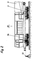
- FIG. 1 to 4 show a machine for the installation of sand 5 or ballast between a formation 1 and a track 2.
- a pivotable conveyor belt 42, a chute 40 lying transversely to the working direction, which is located above the material installation area, and a compacting device 30 are arranged in order to remove sand 5 or ballast from behind the rear Bogie 4 coupled transport device, ie to be taken up by the conveyor belt 100, to be conveyed by means of a first conveyor belt 14 to approximately the middle of the bridge 6, to be transferred to the pivotable second conveyor belt 42 via a stationary funnel 13 and to be distributed by means of the latter, then to be leveled and / or compacted.
- the bridge 6 is self-supporting over its entire length and has a rear lifting device 20 for the track 2 in the working direction in front of the rear bogie 4, which is attached to the bridge 6 by hydraulic lifting arms and is known Way with lifting rollers 21 under the rail heads.
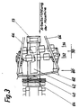
- a compactor device 30 which consists of two rows 32 and 34 of spaced-apart soil compactors 36 which run transversely to the working direction, the soil compactors 36 of the second row 34 having a transverse offset with respect to the soil compactors 36 of the first row 32 and thereby being set to a gap.
- the relative movement of the soil compactors compared to the machine is zero.
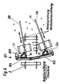
- FIG. 4 shows a further exemplary embodiment of the compressor device 30, which in the embodiment shown consists of two guides 38 arranged essentially in the longitudinal direction of the machine and two soil compactors 36 movably arranged thereon.
- the guides 38 are articulated at one end 38a to the leveling device 60, the other end 38b is freely movable.
- the soil compactors 36 are displaceably guided along the guides 38 and move during operation along these guides when moving parts, for example a bottom plate subjected to vibration, compact the sand or gravel underneath.
- actuating cylinder / piston arrangements 39 are provided, which allow the guides 38 to be pivoted about their articulation point 38a.
- the vibration of the base plate is generated by an eccentric rotating in the base compactor, which at the same time brings about the longitudinal displacement of the base compactor along the guide 38. This ensures that the soil compactors 36 work with a movement relative to the entire machine when compacting, while compacting sand prevents the soil compactors 36 from working too long in the same place and loosening the compacted sand underneath again.
- FIG. 4 Another advantage of the embodiment according to FIG. 4 is that the guides 38 can be set slightly outwards against the longitudinal direction or working direction of the machine, depending on the width of the track bed to be compacted, so that the working width of the compressor device 30 Width of the track bed can be adjusted. In addition, it is avoided that transverse troughs are formed, since the soil compactors 36 essentially overlap in the longitudinal direction of the machine.
- a known vibrating screed can be used instead of surface compactors 36 especially for ballast compaction.
- a leveling device 60 is designed as a leveling plow, which extends over the entire working width of the machine, the plow tip of which is designed as a joint and which consists of at least two telescopic horizontal sections 62 and 64 which are attached to arms 66 at their ends are, which in turn are articulated on the bridge 6.
- the compressor device 30 is also seated on the arms 66.
- the leveling plow is height adjustable. There is a receiver 70 above the leveling plow, which responds to signals from a direction finder 72, which is set up sufficiently far in front of the machine in the working direction and determines the respective height of the sand or gravel layer to be applied. Depending on the direction-finding signals received, the leveling plow can be adjusted manually or automatically to an appropriate height.
- a pivotable second conveyor belt 42 is arranged above the leveling plow and the compressor device 30, the discharge end of which - in the working direction - ends before the leveling plow via a pouring trough 40 arranged transversely to the working direction of the machine.
- the pivotable conveyor belt 42 By means of the pivotable conveyor belt 42, the bedding material to be dispensed, sand 5 or ballast, is distributed according to the required width of the formation protection layer or the ballast bed, then leveled by the leveling plow and then compacted by the compressor device 30.
- the chute 40 guides the bedding material into the sleeper compartments.
- a front track lifting device 22 which is also arranged on the bridge 6 via hydraulically actuated lifting arms and engages under the rail heads by means of lifting rollers 21.
- the receptacles for surface compactor 36 can be swung out in such a way that the embankment of the filled and leveled sand or gravel layer can be compacted with a surface compactor 36 arranged at the end of these receptacles.
- the front bogie 3 of the machine, on which the front end of the bridge 6 is supported, is at the same time the rear bogie of the drive car 90, which - in the embodiment shown, compare in particular FIG. 2 - has another bogie 96 of its own and in addition to the Drive units also includes the control units for the machine.
- the operation of the machine during work travel can include from the cabin 15 arranged on the bridge 6.
- the working devices of the machine can be locked in the respective transport position below the bridge 6.
- the compact arrangement of the work equipment under the bridge 6, in particular the compact arrangement of the pouring channel 40, the leveling plow and the compacting device 30, enables the high-quality installation of a level protection layer made of sand 5 and - in a second operation - a corresponding ballast bed is deposited on this level protection layer , in particular because of the advantageously arranged compressor device 30, a high working speed of the individual operations can be achieved.
- a method for converting the superstructure of a web body is described with reference to FIGS. 5 to 9.
- the track 2 is picked up and the old ballast 50 is removed up to the old planum 1a.
- the old ballast 50 is transported away in the working direction.
- Track 2 is placed on the old planum 1a.
- the track 2 is raised and a formation protection layer, preferably sand 5, is introduced.
- Track 2 is placed on the formation protection layer.
- the track 2 is again picked up and the ballast is inserted and the track 2 on the or. stored in the gravel.
- any required layer thickness of the superstructure of a web body to be renovated can be absorbed.
- the sand 5 After the sand 5 has been introduced, it is generally leveled and / or compacted.
- the method allows the deeper-lying partial layer to be leveled and / or compacted before the introduction of a partial layer of sand 5, the surface of the partial layer possibly being loosened beforehand.
- the introduction of partial layers guarantees the compaction of sand 5 down to the bottom of the formation protection layer. If necessary, the sand 5 must be moistened before it is introduced or compacted.
Claims (28)
- Machine pour la mise en place du sable ou du ballast entre la plate-forme et les rails d'une voie ferrée comprenant une zone de travail délimitée par un boggie avant et un boggie arrière définis par rapport au sens de travail, un pont reliant les boggies, ainsi que des dispositifs de levage montés dans la zone de travail pour le levage de la voie et des dispositifs pour le traitement du sable ou du ballast dans la zone de travail sur des paliers de voie exempts de ballast, lorsque les rails sont soulevés,
caractérisée en ce que le pont (6) est un pont autoporteur sur toute sa longueur, qu'un premier convoyeur (14) est monté de l'une des extrémités du pont jusque sensiblement au milieu du pont (6), en ce qu'au moins un deuxième convoyeur (42), relié au premier et pouvant être déplacé dans le sens horizontal et/ou vertical, est monté au-dessous du pont (6), et que des dispositifs de levage (20, 22) des rails (2) sont montés respectivement derrière le boggie avant (3) et devant le boggie arrière (4). - Machine pour la mise en place du sable ou du ballast entre la plate-forme et les rails d'une voie ferrée selon la revendication 1, caractérisée en ce qu'un point de déversement (13) est monté entre les convoyeurs (14, 42).
- Machine selon la revendication 1 ou 2, caractérisée en ce qu'au moins un dispositif de régalage (60) est prévu, lequel peut être installé au-dessous des rails soulevés (2) pour le régalage du sable (5) ou du ballast précédemment déversé par les convoyeurs (14, 42).
- Machine selon l'une quelconque des revendications précédentes, caractérisée en ce qu'au moins un dispositif de compactage (30) est prévu, qui, placé sous les rails soulevés (2), compacte le sable ou le ballast déversé, après le travail exécuté par le dispositif de régalage (60).
- Machine selon l'une quelconque des revendications précédentes, caractérisée en ce que l'extrémité de déversement du deuxième convoyeur (42), le dispositif de régalage (60), puis le dispositif de compactage (30) sont montés respectivement l'un derrière l'autre dans le sens inverse du sens de travail.
- Machine pour la mise en place du sable ou du ballast entre la plate-forme et les rails d'une voie ferrée selon l'une quelconque des revendications 3 à 5, caractérisée en ce que le(s) dispositif(s) de régalage (60) peut ou peuvent être orienté(s) à l'aide de bras (66) mobiles, fixés contre le pont (6).
- Machine pour la mise en place du sable ou du ballast entre la plate-forme et les rails d'une voie ferrée selon l'une quelconque des revendications 3 à 6, caractérisée en ce que le dispositif de régalage (60) est muni d'un bouteur réglable en hauteur.
- Machine pour la mise en place du sable ou du ballast entre la plate-forme et les rails d'une voie ferrée selon la revendication 7, caractérisée en ce que l'extrémité avant du bouteur est articulée.
- Machine pour la mise en place du sable ou du ballast entre la plate-forme et les rails d'une voie ferrée selon la revendication 7 ou 8, caractérisée en ce que les lames du bouteur sont munies de pièces télescopiques (62, 64).
- Machine pour la mise en place du sable ou du ballast entre la plate-forme et les rails d'une voie ferrée selon l'une quelconque des revendications 1 à 9, caractérisée en ce qu'à l'extrémité de déversement du deuxième convoyeur (42) est montée une trémie de réception (40) disposée transversalement par rapport au sens de travail et au-dessus des rails (2).
- Machine pour la mise en place du sable ou du ballast entre la plate-forme et les rails d'une voie ferrée selon l'une quelconque des revendications 3 à 10, caractérisée en ce qu'en amont du dispositif de régalage (60) est monté un récepteur (70), qui communique avec le dispositif de régalage (60), réagit aux signaux d'un dispositif de repérage (72), et la hauteur de réglage du (des) dispositif(s) de régalage (60) est automatiquement régulée.
- Machine pour la mise en place du sable ou du ballast entre la plate-forme et les rails d'une voie ferrée selon l'une quelconque des revendications 3 à 11, caractérisée en ce qu'une machine pour ameublir la couche de recouvrement du palier de voie ou l'ancien palier de voie (1a) est installée devant le dispositif de régalage (60) par rapport au sens de travail de la machine.
- Machine pour la mise en place du sable ou du ballast entre la plate-forme et les rails d'une voie ferrée selon l'une quelconque des revendications 1 à 12, caractérisée en ce que deux deuxièmes convoyeurs (42) sont montés l'un à côté de l'autre et exécutent un mouvement de pivotement dans le même sens ou dans le sens inverse.
- Machine pour la mise en place du sable ou du ballast entre la plate-forme et les rails d'une voie ferrée selon l'une quelconque des revendications 1 à 13, caractérisée en ce qu'à l'extrémité de déversement de chaque deuxième convoyeur (42) est montée une trémie de réception (40), disposée transversalement par rapport au sens de travail de la machine et au-dessus des rails (2).
- Machine pour la mise en place du sable ou du ballast entre la plate-forme et les rails d'une voie ferrée selon l'une quelconque des revendications 4 à 14, caractérisée en ce que le dispositif de compactage (30) comprend plusieurs engins de compactage du sol (36), séparés les uns des autres et disposés en rangées (32, 34) placées transversalement par rapport au sens de travail, ceux-ci sont montés sur l'une (32) et l'autre rangée (34) par intervalles décalés fixes et compactent le sol sur sensiblement la largeur de travail du dispositif de régalage.
- Machine pour la mise en place du sable ou du ballast entre la plate-forme et les rails d'une voie ferrée selon la revendication 15, caractérisée en ce que le dispositif de compactage (30) est articulé de manière fixe contre la machine et en ce que le mouvement relatif de l'engin de compactage du sol (36) par rapport au sens de travail de la machine est égal à zéro.
- Machine pour la mise en place du sable ou du ballast entre la plate-forme et les rails d'une voie ferrée en particulier selon l'une quelconque des revendications 1 à 14, caractérisée en ce que le dispositif de compactage (30) comprend au moins un système de guidage (38) parallèle ou oblique ou courbe par rapport au sens de travail de la machine et au moins un engin de compactage du sol (36) automobile.
- Machine pour la mise en place du sable ou du ballast entre la plate-forme et les rails d'une voie ferrée selon la revendication 17, caractérisée en ce que le système de guidage (38) est articulé de manière fixe contre un dispositif (30, 60) ou contre la machine elle-même et l'engin de compactage du sol (36) est relié de manière mobile au système de guidage (38).
- Machine pour la mise en place du sable ou du ballast entre la plate-forme et les rails d'une voie ferrée selon la revendication 17, caractérisée en ce que le système de guidage (38) est monté de manière mobile contre un dispositif (30, 60) ou contre la machine elle-même et l'engin de compactage du sol (36) est articulé de manière fixe contre le système de guidage (38).
- Machine pour la mise en place du sable ou du ballast entre la plate-forme et les rails d'une voie ferrée selon l'une quelconque des revendications 4 à 14, caractérisée en ce que le dispositif de compactage (30) ou le ou les engin(s) de compactage du sol (36) est ou sont monté(s) séparément de la machine.
- Machine pour la mise en place du sable ou du ballast entre la plate-forme et les rails d'une voie ferrée selon l'une quelconque des revendications 4 à 20, caractérisée en ce que le dispositif de compactage (30) peut être bloqué sous le pont (6) dans une position de transport séparée.
- Machine pour la mise en place du sable ou du ballast entre la plate-forme et les rails d'une voie ferrée selon l'une quelconque des revendications 1 à 21, caractérisée en ce qu'au moins un engin de compactage du sol (36) peut être décalé chaque fois d'un écart latéral par rapport à la machine pour le compactage du talus.
- Machine pour la mise en place du sable ou du ballast entre la plate-forme et les rails d'une voie ferrée selon l'une quelconque des revendications 1 à 22, caractérisée en ce qu'un wagon d'entraînement (90) est disposé devant le boggie avant.
- Machine pour la mise en place du sable ou du ballast entre la plate-forme et les rails d'une voie ferrée selon l'une quelconque des revendications 1 à 21, caractérisée en ce que le pont (6) est monté sur un wagon d'entraînement (90).
- Procédé pour la reconstruction de la voie permanente d'un palier de voie à l'aide d'une machine selon l'une quelconque des revendications 1 à 24, caractérisé en ce que les rails sont tout d'abord soulevés et on retire sous ceux-ci l'ancien ballast (50) jusqu'à l'ancien palier de voie (1a) de la plate-forme et également, le cas échéant, une sous-couche de la plate-forme, et ensuite on replace les rails (2) sur le palier de voie, en ce que les rails (2) sont à nouveau soulevés à l'aide d'une machine selon l'une quelconque des revendications 1 à 24 et on introduit sous les rails une couche de recouvrement du palier de voie en sable (5), en ce que les rails (2) sont ensuite déposés sur la couche de recouvrement du palier de voie, les rails (2) sont à nouveau soulevés à l'aide d'une machine selon l'une quelconque des revendications 1 à 24 et le ballast est déposé sur la couche de recouvrement et en ce que les rails sont enfin déposés sur ou dans le ballast.
- Procédé selon la revendication 25, caractérisé en ce que l'ancien palier de voie (1a) de la plate-forme est ameubli, régalé et/ou compacté avant la mise en place de la couche de recouvrement du palier de voie.
- Procédé selon la revendication 25 ou 26, caractérisé en ce que la couche de recouvrement du palier de voie mise en place ou une sous-couche de la couche de recouvrement du palier de voie est immédiatement régalée et/ou compactée après sa mise en place.
- Procédé selon l'une quelconque des revendications 25 à 27, caractérisé en ce que la couche de recouvrement du palier de voie mise en place ou une sous-couche de la couche de recouvrement du palier de voie est régalée et/ou compactée avant la mise en place d'une autre sous-couche ou du ballast.
Applications Claiming Priority (4)
| Application Number | Priority Date | Filing Date | Title |
|---|---|---|---|
| DE9200256U DE9200256U1 (fr) | 1992-01-11 | 1992-01-11 | |
| DE9200256U | 1992-01-11 | ||
| DE4236487 | 1992-10-29 | ||
| DE4236487A DE4236487C2 (de) | 1992-01-11 | 1992-10-29 | Verfahren zur Erneuerung des Oberbaus eines Bahnkörpers und Maschine zur Verwendung bei diesem Verfahren |
Publications (2)
| Publication Number | Publication Date |
|---|---|
| EP0551835A1 EP0551835A1 (fr) | 1993-07-21 |
| EP0551835B1 true EP0551835B1 (fr) | 1996-08-14 |
Family
ID=25919934
Family Applications (1)
| Application Number | Title | Priority Date | Filing Date |
|---|---|---|---|
| EP93100197A Expired - Lifetime EP0551835B1 (fr) | 1992-01-11 | 1993-01-08 | Dispositif pour la mise en place du sable ou du ballast entre la plate-forme et les rails d'une voie ferrée, et procédé pour remplacer la superstructure de la voie |
Country Status (3)
| Country | Link |
|---|---|
| EP (1) | EP0551835B1 (fr) |
| AT (1) | ATE141360T1 (fr) |
| DE (1) | DE4244958C2 (fr) |
Families Citing this family (4)
| Publication number | Priority date | Publication date | Assignee | Title |
|---|---|---|---|---|
| DE102007037441B3 (de) * | 2007-08-08 | 2009-01-22 | Deutsche Gleis- Und Tiefbau Gmbh | Gleisverfahrbarer Schüttgutverladewagen |
| DE102009041237B4 (de) | 2009-09-11 | 2019-07-11 | Ralf Zürcher | Verfahren zum Sanieren des Gleisunterbaus einer Bahnstrecke |
| CN105383504B (zh) * | 2015-12-11 | 2017-09-12 | 中车山东机车车辆有限公司 | 一种石砟漏斗车的平砟系统 |
| AT518324B1 (de) * | 2016-02-16 | 2018-04-15 | Plasser & Theurer Export Von Bahnbaumaschinen Gmbh | Gleisbaumaschine und Verfahren zur Verdichtung eines Schotterbettes |
Family Cites Families (7)
| Publication number | Priority date | Publication date | Assignee | Title |
|---|---|---|---|---|
| DE1534109C2 (de) * | 1965-12-10 | 1975-01-16 | Rheiner Maschinenfabrik Windhoff Ag, 4440 Rheine | Pflugartige Einrichtung zum Verteilen und Profilieren des Bettungsschottes eines Gleises |
| US3610157A (en) * | 1969-06-11 | 1971-10-05 | Mikhail Antonovich Plokhotsky | Machine for constructing and repairing railway tracks |
| AT317965B (de) * | 1969-12-18 | 1974-09-25 | Plasser Bahnbaumasch Franz | Maschine zum Aufnehmen, Reinigen und Wiedereinbringen des Bettungsschotters von Eisenbahngleisen |
| US4136618A (en) * | 1977-06-06 | 1979-01-30 | Boyer Jean Jacques | Railroad lifting device for ballast cleaning and levelling machines |
| AT359113B (de) * | 1978-06-16 | 1980-10-27 | Plasser Bahnbaumasch Franz | Selbstfahrbare gleisbett-reinigungsmaschine |
| AT379176B (de) * | 1981-12-22 | 1985-11-25 | Plasser Bahnbaumasch Franz | Fahrbare anlage und verfahren zur kontinuierlich fortschreitenden sanierung des gleisunterbaues |
| ATA126486A (de) * | 1986-05-13 | 1987-05-15 | Wageneder Sbm Gmbh | Auf schienen verfahrbarer umbauwagen fuer gleisanlagen |
-
1992
- 1992-10-29 DE DE4244958A patent/DE4244958C2/de not_active Expired - Fee Related
-
1993
- 1993-01-08 EP EP93100197A patent/EP0551835B1/fr not_active Expired - Lifetime
- 1993-01-08 AT AT93100197T patent/ATE141360T1/de not_active IP Right Cessation
Also Published As
| Publication number | Publication date |
|---|---|
| DE4244958C2 (de) | 2001-02-01 |
| ATE141360T1 (de) | 1996-08-15 |
| EP0551835A1 (fr) | 1993-07-21 |
Similar Documents
| Publication | Publication Date | Title |
|---|---|---|
| EP0255564B1 (fr) | Machine pour remplacer ou rénover respectivement les rails et les traverses d'une voie existante | |
| DE3035910C2 (fr) | ||
| DE3227725A1 (de) | Fahrbare anlage und verfahren zur kontinuierlich fortschreitenden sanierung des gleisunterbaues | |
| DD154623A5 (de) | Fahrbare schotterbett-reinigungsmaschine und verfahren zur behandlung des bettungsschotters | |
| DE3634399C2 (de) | Fahrbare Gleis-Stopf-, Nivellier- und Richtmaschine | |
| EP1172481B1 (fr) | Machine de renouvellement d'une voie ferrée | |
| DE3634397C2 (de) | Fahrbare Anlage zum Reinigen und anschließenden Verdichten der Schotterbettung von Gleisen | |
| DE4237712C2 (de) | Anlage zur Herstellung einer Planumschutzschicht | |
| DE3819717A1 (de) | Kontinuierlich (non-stop) verfahrbare gleisbaumaschine | |
| EP0771909B1 (fr) | Machine pour le démontage d'une ancienne voie ferrée et l'installation d'une nouvelle voie | |
| EP0609647B1 (fr) | Machine pour le renouvellement ou nettoyage d'un lit de ballast | |
| EP1179634B1 (fr) | Machine de renouvellement d'une voie ferrée | |
| DE3106063A1 (de) | Gleisbaumaschine mit einer schotterbett-raeum- und planiervorrichtung | |
| DE3634398C2 (de) | Fahrbare Anlage zur kontinuierlichen Erneuerung der Schienen und Schwellen eines Gleises | |
| EP0551835B1 (fr) | Dispositif pour la mise en place du sable ou du ballast entre la plate-forme et les rails d'une voie ferrée, et procédé pour remplacer la superstructure de la voie | |
| EP0056497A1 (fr) | Wagon-cadre dans un train pour effectuer l'assainissement du sous-sol des voies de chemin de fer | |
| DE202008003589U1 (de) | Gleiswegsanierungsmaschine mit Tragschichtfräse | |
| EP1195468A2 (fr) | Machine de renouvellement d'une voie ferrée | |
| DE2557372C2 (de) | Fahrbare Gleisbaumaschine, zum Aufnehmen, Verteilen und Wiedereinbringen von voneinander getrennten Bettungsmaterialien, insbesondere Weichenreinigungsmaschine | |
| EP0239712B1 (fr) | Machine mobile de travail sur voie pour enlever, nettoyer et mettre en place le ballast et comportant un appareil de compactage du ballast | |
| DE2714050C2 (fr) | ||
| CH474618A (de) | Verfahren zum Reinigen, Nivellieren und Verdichten des Schotters von Gleisbettungen und gleichzeitigem Stabilisieren des Erdplanums bei liegendem Gleis, sowie Maschine zur Durchführung des Verfahrens | |
| DE4236487C2 (de) | Verfahren zur Erneuerung des Oberbaus eines Bahnkörpers und Maschine zur Verwendung bei diesem Verfahren | |
| AT404947B (de) | Wagen zur einschotterung eines gleises | |
| AT400862B (de) | Gleisbaumaschine mit höhenverstellbarem gleishebeaggregat |
Legal Events
| Date | Code | Title | Description |
|---|---|---|---|
| PUAI | Public reference made under article 153(3) epc to a published international application that has entered the european phase |
Free format text: ORIGINAL CODE: 0009012 |
|
| AK | Designated contracting states |
Kind code of ref document: A1 Designated state(s): AT BE CH DE FR IT LI NL |
|
| 17P | Request for examination filed |
Effective date: 19931112 |
|
| 17Q | First examination report despatched |
Effective date: 19950131 |
|
| GRAH | Despatch of communication of intention to grant a patent |
Free format text: ORIGINAL CODE: EPIDOS IGRA |
|
| GRAH | Despatch of communication of intention to grant a patent |
Free format text: ORIGINAL CODE: EPIDOS IGRA |
|
| GRAA | (expected) grant |
Free format text: ORIGINAL CODE: 0009210 |
|
| AK | Designated contracting states |
Kind code of ref document: B1 Designated state(s): AT BE CH DE FR IT LI NL |
|
| REF | Corresponds to: |
Ref document number: 141360 Country of ref document: AT Date of ref document: 19960815 Kind code of ref document: T |
|
| REF | Corresponds to: |
Ref document number: 59303386 Country of ref document: DE Date of ref document: 19960919 |
|
| ITF | It: translation for a ep patent filed |
Owner name: MODIANO & ASSOCIATI S.R.L. |
|
| ET | Fr: translation filed | ||
| PG25 | Lapsed in a contracting state [announced via postgrant information from national office to epo] |
Ref country code: LI Effective date: 19970131 Ref country code: CH Effective date: 19970131 |
|
| PLBE | No opposition filed within time limit |
Free format text: ORIGINAL CODE: 0009261 |
|
| STAA | Information on the status of an ep patent application or granted ep patent |
Free format text: STATUS: NO OPPOSITION FILED WITHIN TIME LIMIT |
|
| PG25 | Lapsed in a contracting state [announced via postgrant information from national office to epo] |
Ref country code: BE Effective date: 19970731 |
|
| 26N | No opposition filed | ||
| REG | Reference to a national code |
Ref country code: CH Ref legal event code: PL |
|
| NLS | Nl: assignments of ep-patents |
Owner name: FRANZ PLASSER BAHNBAUMASCHINEN- INDUSTRIEGESELLSCH |
|
| REG | Reference to a national code |
Ref country code: FR Ref legal event code: CD |
|
| PGFP | Annual fee paid to national office [announced via postgrant information from national office to epo] |
Ref country code: IT Payment date: 20100123 Year of fee payment: 18 Ref country code: FR Payment date: 20100211 Year of fee payment: 18 |
|
| PGFP | Annual fee paid to national office [announced via postgrant information from national office to epo] |
Ref country code: DE Payment date: 20100318 Year of fee payment: 18 Ref country code: AT Payment date: 20091215 Year of fee payment: 18 |
|
| PGFP | Annual fee paid to national office [announced via postgrant information from national office to epo] |
Ref country code: NL Payment date: 20100127 Year of fee payment: 18 |
|
| REG | Reference to a national code |
Ref country code: NL Ref legal event code: V1 Effective date: 20110801 |
|
| REG | Reference to a national code |
Ref country code: FR Ref legal event code: ST Effective date: 20110930 |
|
| PG25 | Lapsed in a contracting state [announced via postgrant information from national office to epo] |
Ref country code: FR Free format text: LAPSE BECAUSE OF NON-PAYMENT OF DUE FEES Effective date: 20110131 |
|
| PG25 | Lapsed in a contracting state [announced via postgrant information from national office to epo] |
Ref country code: AT Free format text: LAPSE BECAUSE OF NON-PAYMENT OF DUE FEES Effective date: 20110108 |
|
| REG | Reference to a national code |
Ref country code: DE Ref legal event code: R119 Ref document number: 59303386 Country of ref document: DE Effective date: 20110802 |
|
| PG25 | Lapsed in a contracting state [announced via postgrant information from national office to epo] |
Ref country code: NL Free format text: LAPSE BECAUSE OF NON-PAYMENT OF DUE FEES Effective date: 20110801 Ref country code: IT Free format text: LAPSE BECAUSE OF NON-PAYMENT OF DUE FEES Effective date: 20110108 |
|
| PG25 | Lapsed in a contracting state [announced via postgrant information from national office to epo] |
Ref country code: DE Free format text: LAPSE BECAUSE OF NON-PAYMENT OF DUE FEES Effective date: 20110802 |