EP0239712B1 - Machine mobile de travail sur voie pour enlever, nettoyer et mettre en place le ballast et comportant un appareil de compactage du ballast - Google Patents
Machine mobile de travail sur voie pour enlever, nettoyer et mettre en place le ballast et comportant un appareil de compactage du ballast Download PDFInfo
- Publication number
- EP0239712B1 EP0239712B1 EP86890088A EP86890088A EP0239712B1 EP 0239712 B1 EP0239712 B1 EP 0239712B1 EP 86890088 A EP86890088 A EP 86890088A EP 86890088 A EP86890088 A EP 86890088A EP 0239712 B1 EP0239712 B1 EP 0239712B1
- Authority
- EP
- European Patent Office
- Prior art keywords
- ballast
- track
- machine
- drive
- consolidating
- Prior art date
- Legal status (The legal status is an assumption and is not a legal conclusion. Google has not performed a legal analysis and makes no representation as to the accuracy of the status listed.)
- Expired
Links
Images
Classifications
-
- E—FIXED CONSTRUCTIONS
- E01—CONSTRUCTION OF ROADS, RAILWAYS, OR BRIDGES
- E01B—PERMANENT WAY; PERMANENT-WAY TOOLS; MACHINES FOR MAKING RAILWAYS OF ALL KINDS
- E01B27/00—Placing, renewing, working, cleaning, or taking-up the ballast, with or without concurrent work on the track; Devices therefor; Packing sleepers
- E01B27/06—Renewing or cleaning the ballast in situ, with or without concurrent work on the track
- E01B27/10—Renewing or cleaning the ballast in situ, with or without concurrent work on the track without taking-up track
Definitions
- the invention relates to a track-moving track construction machine, in particular ballast bed cleaning machine, with a conveyor or clearing chain guided around the track for picking up the ballast from the area below the track, a screening system which can be loaded with the picked up ballast, and with a device for reintroducing the cleaned ballast by dropping above the track in the area behind the conveyor or clearing chain and a beam-shaped ballast compacting device that runs under the track structure consisting of sleepers and rails and extends transversely to the machine's longitudinal direction, each of which is attached to the machine frame at the end via support posts connected to a drive is.
- such a ballast bed cleaning machine with a conveyor or clearing chain for picking up the ballast from the area below the track is already known.
- the conveyor or clearing chain is followed by a screening system in the working direction for cleaning the ballast that has been picked up.
- a device designed as a discharge conveyor belt is provided for the distributed reintroduction of the cleaned ballast by discharge onto the exposed formation in the area immediately behind the conveyor or clearing chain.
- a leveling and compacting device carried out beneath the track grate is articulated on the machine frame via supports arranged as parallelogram guides and adjustable in height by means of a swivel drive.
- the leveling device arranged upstream in the working direction of the compacting device is formed from two leveling chains which are articulated on the ends at the ends and can be pivoted by a drive about a vertical axis and are each connected to a rotary drive for rotation in the horizontal plane.
- the longitudinal girder connected to the leveling device via the longitudinal girder extending in the longitudinal direction of the machine is formed by a bar running transversely to the longitudinal direction of the machine, the outer ends of which are elastically yieldingly connected to one of the two longitudinal girders and which can be set in motion by a vibration drive.
- the ballast which is thrown relatively irregularly from the discharge conveyor belt through the track onto the level, is brought to the same height with the rotating leveling chains and then compressed from above by the compacting device.
- This device is relatively extensive since two units - a leveling and compacting device - are necessary and therefore often requires a higher lifting of the track, since the two height-adjustable devices are arranged between the upper ballast bed level and the track frame.
- the compaction effect is not always sufficient, as there are often gravel gaps due to the irregularly dropped gravel. This is disadvantageous where the sleepers then come to rest.
- a ballast bed cleaning machine with a conveyor or clearing chain which is passed under the track for receiving the ballast is also known.
- This conveyor or clearing chain is followed by a screening system for cleaning the ballast.
- One or two discharge conveyor belts which can be pivoted in the horizontal plane are provided as a device for the distributed reintroduction of the cleaned ballast from the screening plant onto the exposed planum.
- the conveyor or clearing chain is further followed by a leveling device, which consists of an articulated bar arrangement extending over the entire threshold length. This consists of a central cross-member running parallel to the longitudinal direction of the sleeper and two outer cross-members connected to it by joints.
- the two outer ends of the outer cross links and the joints are fastened to the conveyor or clearing chain with cables so that they can move freely.
- the ballast thrown off by the discharge conveyor belt should be distributed approximately uniformly, but ballast gaps also often occur due to the relatively rough distribution effect of the distribution belts.
- the object of the invention is that in ballast treatment machines with cleaning systems, such as conveyor and clearing chain with track lifting device and reintroduction of the cleaned ballast, the thrown ballast is subjected to an improved assignment or an accumulation to the correct locations is achieved in order to provide the track structure with a better support to enable.
- the object of the invention is now achieved with the track-moving track construction machine described in the introduction in that the ballast compacting device designed as a plate-shaped compacting bar is arranged directly in or in front of the area of the ballast thrown onto the formation, and in that the drive connected to the support post for a continuous about back and forth pendulum movement in the track plane - for pre-compaction of the ballast against the working direction - is formed.
- Such a compacting device enables an immediate displacement of the ballast dropped between the sleepers onto the formation in a continuous manner Schoppvorgang also below the thresholds, a pre-compression of the ballast can be achieved by their resistance.
- the track is already in a desired and controllable position on pre-compacted sleeper supports immediately after the ballast discharge, so that the load exerted on the track by the following running gear of the track construction machine can be exploited for a further uniform pre-compression of the sleeper supports.
- a particularly preferred embodiment of the invention consists in that the loop-like compacting bar for pushing together the thrown-up ballast is formed from two half-parts which are mirror images of the machine longitudinal plane of symmetry, each around a vertical axis in the area of the support post attached to the machine frame with its upper end are pivotally mounted for disengagement outside the sleepers and are each connected to a drive attached to the support post.
- This two-part design of the compacting bar means that it can be put into operation and taken out of operation quickly and easily by pivoting the pivotable half-parts on the support post into a rest position located to the side of the track or into a working position below the sleepers. This saves time-consuming retrofitting work.
- a particularly advantageous embodiment of the invention is characterized in that the two half parts can be connected to one another by a releasable stiffening plate.
- the strength of the compression bar formed by both half parts is increased significantly in a simple manner.
- the pre-compression effect for the. Ballast can still be improved, and the large mechanical stresses caused by the continuously cyclical impact movement are better withstood.
- the compression bar which is designed as a two-part Schopp bar
- a support post which is articulated on the machine frame and is designed as a two-sided lever, the upper part of which is connected to a hydraulic cylinder piston which can be pivoted -Drive trained drive
- the two support posts for the two-part Schopp-beam can be operated independently by loosening the stiffening plate or pivoted out of engagement.
- Such a simple design of the support post as a two-part lever is particularly suitable for an efficient transmission of large compacting forces from the drive to the compacting bar.
- a preferred embodiment of the invention is characterized in that the Schopp beam has a convex curvature in cross-section, seen from top to bottom, the bottom edge of which in the front part of the curvature in the working direction and the top edge in the direction of compaction up to immediately near the threshold bottom edge is sufficient, with a reinforcing plate for attachment to the beam itself and to the support post connected above the machine frame is provided at the outer end.
- the curvature enables an immediate drainage of the ballast, which is continuously thrown off the ballast outlet of the machine and temporarily falls onto the compression beam.
- a reinforcement plate With the arrangement of a reinforcement plate, a full-surface fastening of the curved Schopp beam in the area of the support posts is possible for a high load capacity.
- the compacting device or each half part of the Schopp bar which is designed as a continuous Schopp bar, can preferably be connected to a vibration drive. Thanks to the vibration drive, the Schopp bar can be set to vibrate in addition to the cyclical stroke movement. On the one hand, this increases the compacting effect and, on the other hand, an even faster flow of the ballast falling on the Schopp beam.
- the compacting device designed as a Schopp bar is assigned a hold-down device, preferably with a height adjustment drive, which is articulated on the machine frame and arranged upstream in the working direction and can be unrolled via a pair of flange wheels on the track.
- a hold-down device in addition to the weight of the track, a controlled force can be exerted in the direction of the level, so that the compacting effect of the Schopp beam is still can also be increased.
- the hold-down device avoiding an uncontrolled track elevation due to the compacting effect, an exact and uniform fixation of the track in the desired target position is achieved.
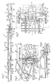
- the ballast bed cleaning machine 1 shown in FIG. 1 is composed of a total of three interconnected work vehicles 2, 3 and 4, which can be moved via rail carriages 5 on a track 8 formed from sleepers 6 and rails 7.
- an endless conveyor or clearing chain 9 which is guided around the track 8, is fastened on a machine frame 10 with a drive.
- a height-adjustable track lifting device 11 is provided in the area of this conveyor or clearing chain 9.
- a work cabin 13 is connected to the machine frame 10 above an excavation area 14 of the ballast bed. This is followed by a hold-down device 15 that can be rolled off the track 8 and a ballast compacting device 16.
- a screening plant 17 is arranged on a machine frame 19 with two independent screening units 18 which are arranged in a V-shape one behind the other in the machine longitudinal direction and each have their own vibration drive.
- This screening plant 17 can be fed with the contaminated ballast picked up by the conveyor or clearing chain 9 by means of a transport conveyor belt 20 shown with short arrows and two throw-in conveyor belts 21.
- the overburden separated from the ballast in the screening plant 17 passes, for example, to an upstream loading wagon via an overburden conveyor belt 22 shown with dash-dotted arrows.
- ballast distributing device 23 formed from a plurality of conveyor belts arranged one behind the other and shown with long arrows. This is designed to transport the cleaned ballast via a buffer 24 to a first ballast outlet 25 located in the area of the compacting device 16 and to a second ballast outlet 26 located on the rear work vehicle 4.
- This second ballast outlet 26 is formed by a ballast accumulator 27 with controllable outlet openings.
- the first sho't terausldivider 25 is to create a first gravel layer 28 between ground level and platform 8 and the second gravel outlet 26 for creation of a second, the threshold compartments filling gravel layer 29th
- a track tamping and lifting straightening unit 30 is arranged on a machine frame 31 so as to be displaceable in the longitudinal direction of the vehicle via a drive.
- the ballast distributing device 23 can be extended by a conveyor belt 32 arranged downstream of the ballast store 27 to beyond the rear end of the machine, a pivotable deflection element being provided in the front, end region of the conveyor belt 32 on the receiving side.
- the entire ballast or a part thereof can optionally be diverted into the ballast store 27 located thereunder or as excess ballast via the conveyor belt 32 to a subsequent loading wagon.
- All of the conveyor belts are expediently channel-shaped, as a result of which lateral falling of ballast or overburden is prevented even with long transport routes.
- the ballast compacting device 16 shown enlarged in FIGS. 2 and 3 consists of vertical support posts 33 arranged on the side of the track 8, which are pivotably mounted on the machine frame 10 in a bearing point 34 about an axis 35 running transversely to the longitudinal direction of the vehicle. These two fork-shaped support posts 33 are extended in their lower end region by a reinforcing plate 36 which is connected to the end of a plate-shaped compacting or Schopp beam 37 arranged transversely to the track 8.
- the compression device 16 is arranged directly in the region of the ballast thrown off in the first ballast outlet 25.
- a drive 38 which is connected to the support post 33 and is articulated on the machine frame 10, is designed for a continuous oscillating movement, for example reciprocating in the track plane and in the longitudinal direction of the track - for pre-compaction of the ballast against the working direction.
- the two fork-shaped ends of the support post 33 are connected to one another by a connecting plate 39.
- the one for pushing the thrown gravel together The compacting bar is formed from two half-parts 40 that are mirror images of the machine's longitudinal plane of symmetry, each of which is mounted in the area of the support post 33 which is fastened with its upper end to the machine frame about a vertical axis 41 to the outside for external engagement outside the sleepers and each with one on the support post 33 attached drive 42 are connected.
- the vertical axis 41 is formed by a crank rod 43 rotatably mounted in the connecting plate 39, with the lower end with the reinforcing plate 36 and thus with the associated half-part 40 and with its upper end with the drive 42.
- the two half parts 40 of the Schopp beam 37 are connected to one another in their free end region located in the middle of the track by a releasable stiffening plate 44.
- the Schopp bar 37 has in cross section a - from top to bottom - convex curvature 45, the lowermost edge of which extends in the front part of the curvature 45 in the working direction and the uppermost edge in the compacting direction up to immediately near the threshold lower edge.
- Each half part 40 of the Schopp bar 37 is connected to a vibration drive 46.
- the compacting device 16 is preceded by the hold-down device 15, which is articulated on the work cabin 13 and can be rolled off on the track 8 via a pair of flange wheels 47 and has a height adjustment drive 48.
- the work units and movement sequences downstream of the work cabin 13 can be controlled from a central control device 49.
- the first ballast outlet is formed by a schematically indicated ballast distribution chute 50 with two outlets running transversely to the longitudinal direction of the track to form two sleeper support banks 51.
- a diverting element 52 is provided for dividing the ballast into a first quantity thrown off in the first ballast outlet 25 and into a remaining quantity transported to the second ballast outlet 26. This is pivotally mounted about an axis running transversely to the machine longitudinal direction.
- the method of operation of the ballast bed cleaning machine 1 shown in FIGS. 1 to 3 is as follows:
- the contaminated ballast is continuously conveyed up through the conveyor or clearing chain 9 onto the transport conveyor belt 20 and is thrown from there via the throw-in conveyor belts 21 onto the screening plant 17.
- the cleaned ballast delivered by this passes via the ballast distribution device 23 against the working direction to the first ballast outlet 25 located in the excavation area 14.
- There - with the position of the deflection element 52 shown in FIG. 2 - part of the transported ballast via the ballast distribution chute 50 between the sleepers thrown onto the formation and a further part of the ballast is fed to the second ballast outlet 26 via the downstream ballast distribution device 23.
- ballast thrown by it via the ballast store 27 is used to fill the intermediate sleeper compartments to form a second ballast layer 29. Should z. B. with less spoil content more cleaned ballast, then the excess ballast that is not required is conveyed on to a subsequent loading wagon by means of the downstream conveyor belt 32 with appropriate pivoting of a deflection member arranged above the ballast store 27.
- the track tamping and lifting / straightening unit 30 continuously corrects the track position and tamping the track.
- the ballast thrown off in the first ballast outlet in the area of the compacting device 16 to form the first ballast layer 28 is moved and precompressed under the sleepers 6 against the working direction by the continuously reciprocating movement caused by the drive 38.
- Fig. 2 the foremost position in this reciprocating movement is shown in full lines and the rearmost position in the working direction with dash-dotted lines.
- the hold-down device 15 with its flange wheel pair 47 is brought into the desired height position.
- the operator located in the work cabin 13 can optionally change the frequency of the back and forth movement of the Schopp bar 37 in accordance with the amount of ballast or the like.
- the two half parts 40 of the Schopp beam 37 are pivoted by actuation of the two drives 42 from their working position shown in full lines in FIG. 3 by 90 ° into the rest position shown in broken lines.
- the pivoting takes place in that the crank rod 43 rotatably mounted in the connecting plate 39 together with the reinforcing plate attached to the lower end is also pivoted through 90 °.
- the half-parts 40 swiveled out to the side of the track 8 can still be brought above the track level by completely retracting the piston rod of the drive 38 into the cylinder.
- a ballast bed cleaning machine 53 shown in FIG. 4 with a machine frame 54 is on chassis 55 a track formed from rails 56 and sleepers 57.
- the ballast picked up via a conveyor or clearing chain 58 is cleaned in a sieve system 59 and dropped onto the subgrade via the discharge conveyor belt 60 through the track.
- a ballast compacting device 61 is provided directly in the area of the thrown up ballast. This consists of support posts 62 which are mounted on the side of the machine frame 54 so as to be pivotable about a transverse axis, and which can be set into a movement which reciprocates approximately in the plane of the track by a drive 63 which is also articulated on the machine frame 54.
- the lower ends of the two support posts 62 are detachably connected to one another in the area below the track by a plate-shaped compression bar 64 with a convex curvature.
- This compacting bar 64 is pushed through the prepared gap at the start of the work and connected to the free ends of the two support posts 62. After completion of the work, the compression bar 64 is released from the support posts 62, so that an unobstructed transfer travel of the ballast bed cleaning machine 53 can be carried out.
Landscapes
- Engineering & Computer Science (AREA)
- Architecture (AREA)
- Civil Engineering (AREA)
- Structural Engineering (AREA)
- Machines For Laying And Maintaining Railways (AREA)
Claims (7)
Priority Applications (8)
| Application Number | Priority Date | Filing Date | Title |
|---|---|---|---|
| DE8686890088T DE3660630D1 (en) | 1986-04-02 | 1986-04-02 | Mobile track-treating machine for removing, cleaning and reintroducing ballast with a ballast compacting device |
| AT86890088T ATE36878T1 (de) | 1986-04-02 | 1986-04-02 | Fahrbare gleisbaumaschine zum aufnehmen, reinigen, und wiedereinbringen des schotters mit einer schotter-verdichteinrichtung. |
| EP86890088A EP0239712B1 (fr) | 1986-04-02 | 1986-04-02 | Machine mobile de travail sur voie pour enlever, nettoyer et mettre en place le ballast et comportant un appareil de compactage du ballast |
| AU66390/86A AU583690B2 (en) | 1986-04-02 | 1986-12-10 | A travelling track maintenance machine for taking up, cleaning and reintroducing ballast comprising a ballast consolidating unit |
| JP62012145A JPS62233304A (ja) | 1986-04-02 | 1987-01-21 | 自走式軌道保守機械 |
| CA000529890A CA1295188C (fr) | 1986-04-02 | 1987-02-17 | Degarnisseuse-cribleuse a dispositif de compactage |
| SU874202120A SU1505446A3 (ru) | 1986-04-02 | 1987-03-13 | Передвижна щебнеочистительна машина |
| DD87301263A DD257655A5 (de) | 1986-04-02 | 1987-03-30 | Fahrbare gleisbaumaschine zum aufnehmen,reinigen und wiedereinbringen des schotters mit einer schotterverdichtereinrichtung |
Applications Claiming Priority (1)
| Application Number | Priority Date | Filing Date | Title |
|---|---|---|---|
| EP86890088A EP0239712B1 (fr) | 1986-04-02 | 1986-04-02 | Machine mobile de travail sur voie pour enlever, nettoyer et mettre en place le ballast et comportant un appareil de compactage du ballast |
Publications (2)
| Publication Number | Publication Date |
|---|---|
| EP0239712A1 EP0239712A1 (fr) | 1987-10-07 |
| EP0239712B1 true EP0239712B1 (fr) | 1988-08-31 |
Family
ID=8196558
Family Applications (1)
| Application Number | Title | Priority Date | Filing Date |
|---|---|---|---|
| EP86890088A Expired EP0239712B1 (fr) | 1986-04-02 | 1986-04-02 | Machine mobile de travail sur voie pour enlever, nettoyer et mettre en place le ballast et comportant un appareil de compactage du ballast |
Country Status (8)
| Country | Link |
|---|---|
| EP (1) | EP0239712B1 (fr) |
| JP (1) | JPS62233304A (fr) |
| AT (1) | ATE36878T1 (fr) |
| AU (1) | AU583690B2 (fr) |
| CA (1) | CA1295188C (fr) |
| DD (1) | DD257655A5 (fr) |
| DE (1) | DE3660630D1 (fr) |
| SU (1) | SU1505446A3 (fr) |
Cited By (1)
| Publication number | Priority date | Publication date | Assignee | Title |
|---|---|---|---|---|
| WO2017140408A1 (fr) * | 2016-02-16 | 2017-08-24 | Plasser & Theurer Export Von Bahnbaumaschinen Gesellschaft M.B.H. | Machine de pose de voie ferrée et procédé de tassement d'un lit de ballast |
Families Citing this family (5)
| Publication number | Priority date | Publication date | Assignee | Title |
|---|---|---|---|---|
| AT387999B (de) * | 1987-05-27 | 1989-04-10 | Plasser Bahnbaumasch Franz | Gleis-schotterbett-reinigungsmaschine mit endloser foerder- bzw. raeumkette |
| US5664633A (en) * | 1995-09-04 | 1997-09-09 | Franz Plasser Bahnbaumaschinen-Industriegesellschaft M.B.H. | Machine for treating a ballast bed |
| DE102007038461B4 (de) * | 2007-08-14 | 2013-06-13 | Rail.One Gmbh | Verfahren zur Sanierung einer Schienenfahrbahn und zugehörige Schienenfahrbahn |
| AT511472B1 (de) * | 2011-09-29 | 2012-12-15 | Plasser Bahnbaumasch Franz | Verfahren zur sanierung einer schotterbettung eines gleises |
| US11313083B2 (en) | 2018-10-04 | 2022-04-26 | Nordco Inc. | Rail anchor applicator and cribber apparatus |
Family Cites Families (4)
| Publication number | Priority date | Publication date | Assignee | Title |
|---|---|---|---|---|
| US2309712A (en) * | 1940-03-22 | 1943-02-02 | Frank H Philbrick | Apparatus for handling ballast in railway roadbeds |
| US2743539A (en) * | 1953-02-19 | 1956-05-01 | Samuel R Hursh | Adjustment mechanism for kicker-type ballast remover |
| DE1157637B (de) * | 1961-08-29 | 1963-11-21 | Kornelius Kissel | Maschine zum Reinigen des Bettungsschotters unter einem Gleis |
| AT329107B (de) * | 1974-07-05 | 1976-04-26 | Plasser Bahnbaumasch Franz | Schotterbettreinigungsmaschine mit planier-vorrichtung |
-
1986
- 1986-04-02 EP EP86890088A patent/EP0239712B1/fr not_active Expired
- 1986-04-02 AT AT86890088T patent/ATE36878T1/de not_active IP Right Cessation
- 1986-04-02 DE DE8686890088T patent/DE3660630D1/de not_active Expired
- 1986-12-10 AU AU66390/86A patent/AU583690B2/en not_active Ceased
-
1987
- 1987-01-21 JP JP62012145A patent/JPS62233304A/ja active Granted
- 1987-02-17 CA CA000529890A patent/CA1295188C/fr not_active Expired - Lifetime
- 1987-03-13 SU SU874202120A patent/SU1505446A3/ru active
- 1987-03-30 DD DD87301263A patent/DD257655A5/de not_active IP Right Cessation
Cited By (2)
| Publication number | Priority date | Publication date | Assignee | Title |
|---|---|---|---|---|
| WO2017140408A1 (fr) * | 2016-02-16 | 2017-08-24 | Plasser & Theurer Export Von Bahnbaumaschinen Gesellschaft M.B.H. | Machine de pose de voie ferrée et procédé de tassement d'un lit de ballast |
| EA037274B1 (ru) * | 2016-02-16 | 2021-03-03 | Плассер Энд Тойрер Экспорт Фон Банбаумашинен Гезельшафт М.Б.Х. | Путевая машина и способ уплотнения щебёночной постели |
Also Published As
| Publication number | Publication date |
|---|---|
| JPH0568562B2 (fr) | 1993-09-29 |
| EP0239712A1 (fr) | 1987-10-07 |
| CA1295188C (fr) | 1992-02-04 |
| JPS62233304A (ja) | 1987-10-13 |
| AU583690B2 (en) | 1989-05-04 |
| DE3660630D1 (en) | 1988-10-06 |
| ATE36878T1 (de) | 1988-09-15 |
| AU6639086A (en) | 1987-10-08 |
| SU1505446A3 (ru) | 1989-08-30 |
| DD257655A5 (de) | 1988-06-22 |
Similar Documents
| Publication | Publication Date | Title |
|---|---|---|
| EP0255564B1 (fr) | Machine pour remplacer ou rénover respectivement les rails et les traverses d'une voie existante | |
| DE2331914C2 (de) | Verfahren und Vorrichtung zum Stabilisieren des Unterbauplanums von Gleisbettungen | |
| DE3117898C2 (fr) | ||
| DE3036007C2 (fr) | ||
| EP0239711B1 (fr) | Installation mobile pour le nettoyage du ballast d'une voie avec dispositif de distribution du ballast | |
| DD207014A5 (de) | Fahrbare anlage und verfahren zur kontinuierlich fortschreitenden sanierung des gleisunterbaues | |
| DE2550391A1 (de) | Verfahren zum entnehmen von bettungsmaterial aus schotterbettungen | |
| DE3634399C2 (de) | Fahrbare Gleis-Stopf-, Nivellier- und Richtmaschine | |
| EP0240648B1 (fr) | Machine à nettoyer le ballast avec appareil de criblage | |
| DE3634397C2 (de) | Fahrbare Anlage zum Reinigen und anschließenden Verdichten der Schotterbettung von Gleisen | |
| DE4237712C2 (de) | Anlage zur Herstellung einer Planumschutzschicht | |
| EP0408839A1 (fr) | Ensemble de machines déplaçable sur voie pour enlever, nettoyer et remettre en place le ballast d'une voie ferrée | |
| DE3543040A1 (de) | Gleisfahrbare maschine zum absaugen des schotters aus einer schotterbettung | |
| EP0499018B1 (fr) | Machine de nettoyage | |
| CH616472A5 (fr) | ||
| EP0609647B1 (fr) | Machine pour le renouvellement ou nettoyage d'un lit de ballast | |
| EP0239712B1 (fr) | Machine mobile de travail sur voie pour enlever, nettoyer et mettre en place le ballast et comportant un appareil de compactage du ballast | |
| DD253267A5 (de) | Fahrbare anlage zur kontinuierlichen erneuerung der schienen und schwellen eines gleises | |
| DE3151030A1 (de) | Fahrbare anlage zur herstellung einer zwischen planum und schotterbett eines gleises verlaufenden schutzschichte | |
| DE2057128C3 (de) | Fahrbare Maschine zum Aufnehmen, Reinigen und Wiedereinbringen des Bettungsschotters von Eisenbahngleisen | |
| EP0551835B1 (fr) | Dispositif pour la mise en place du sable ou du ballast entre la plate-forme et les rails d'une voie ferrée, et procédé pour remplacer la superstructure de la voie | |
| DE2714050C2 (fr) | ||
| AT404947B (de) | Wagen zur einschotterung eines gleises | |
| DE19502450C1 (de) | Gleisgebundene Baumaschine | |
| AT400862B (de) | Gleisbaumaschine mit höhenverstellbarem gleishebeaggregat |
Legal Events
| Date | Code | Title | Description |
|---|---|---|---|
| PUAI | Public reference made under article 153(3) epc to a published international application that has entered the european phase |
Free format text: ORIGINAL CODE: 0009012 |
|
| 17P | Request for examination filed |
Effective date: 19861230 |
|
| AK | Designated contracting states |
Kind code of ref document: A1 Designated state(s): AT BE CH DE FR GB IT LI LU NL SE |
|
| RBV | Designated contracting states (corrected) |
Designated state(s): AT DE FR GB IT SE |
|
| 17Q | First examination report despatched |
Effective date: 19880125 |
|
| GRAA | (expected) grant |
Free format text: ORIGINAL CODE: 0009210 |
|
| AK | Designated contracting states |
Kind code of ref document: B1 Designated state(s): AT DE FR GB IT SE |
|
| REF | Corresponds to: |
Ref document number: 36878 Country of ref document: AT Date of ref document: 19880915 Kind code of ref document: T |
|
| GBT | Gb: translation of ep patent filed (gb section 77(6)(a)/1977) | ||
| REF | Corresponds to: |
Ref document number: 3660630 Country of ref document: DE Date of ref document: 19881006 |
|
| ITF | It: translation for a ep patent filed |
Owner name: ING. A. GIAMBROCONO & C. S.R.L. |
|
| ET | Fr: translation filed | ||
| PLBE | No opposition filed within time limit |
Free format text: ORIGINAL CODE: 0009261 |
|
| STAA | Information on the status of an ep patent application or granted ep patent |
Free format text: STATUS: NO OPPOSITION FILED WITHIN TIME LIMIT |
|
| 26N | No opposition filed | ||
| ITTA | It: last paid annual fee | ||
| EAL | Se: european patent in force in sweden |
Ref document number: 86890088.7 |
|
| REG | Reference to a national code |
Ref country code: GB Ref legal event code: IF02 |
|
| PGFP | Annual fee paid to national office [announced via postgrant information from national office to epo] |
Ref country code: AT Payment date: 20020312 Year of fee payment: 17 |
|
| PG25 | Lapsed in a contracting state [announced via postgrant information from national office to epo] |
Ref country code: AT Free format text: LAPSE BECAUSE OF NON-PAYMENT OF DUE FEES Effective date: 20030402 |
|
| PGFP | Annual fee paid to national office [announced via postgrant information from national office to epo] |
Ref country code: FR Payment date: 20030417 Year of fee payment: 18 |
|
| PGFP | Annual fee paid to national office [announced via postgrant information from national office to epo] |
Ref country code: DE Payment date: 20030430 Year of fee payment: 18 |
|
| PGFP | Annual fee paid to national office [announced via postgrant information from national office to epo] |
Ref country code: GB Payment date: 20040301 Year of fee payment: 19 |
|
| PGFP | Annual fee paid to national office [announced via postgrant information from national office to epo] |
Ref country code: SE Payment date: 20040427 Year of fee payment: 19 |
|
| PG25 | Lapsed in a contracting state [announced via postgrant information from national office to epo] |
Ref country code: DE Free format text: LAPSE BECAUSE OF NON-PAYMENT OF DUE FEES Effective date: 20041103 |
|
| PG25 | Lapsed in a contracting state [announced via postgrant information from national office to epo] |
Ref country code: FR Free format text: LAPSE BECAUSE OF NON-PAYMENT OF DUE FEES Effective date: 20041231 |
|
| REG | Reference to a national code |
Ref country code: FR Ref legal event code: ST |
|
| PG25 | Lapsed in a contracting state [announced via postgrant information from national office to epo] |
Ref country code: IT Free format text: LAPSE BECAUSE OF NON-PAYMENT OF DUE FEES;WARNING: LAPSES OF ITALIAN PATENTS WITH EFFECTIVE DATE BEFORE 2007 MAY HAVE OCCURRED AT ANY TIME BEFORE 2007. THE CORRECT EFFECTIVE DATE MAY BE DIFFERENT FROM THE ONE RECORDED. Effective date: 20050402 Ref country code: GB Free format text: LAPSE BECAUSE OF NON-PAYMENT OF DUE FEES Effective date: 20050402 |
|
| PG25 | Lapsed in a contracting state [announced via postgrant information from national office to epo] |
Ref country code: SE Free format text: LAPSE BECAUSE OF NON-PAYMENT OF DUE FEES Effective date: 20050403 |
|
| EUG | Se: european patent has lapsed | ||
| GBPC | Gb: european patent ceased through non-payment of renewal fee |
Effective date: 20050402 |