EP0056497A1 - Wagon-cadre dans un train pour effectuer l'assainissement du sous-sol des voies de chemin de fer - Google Patents
Wagon-cadre dans un train pour effectuer l'assainissement du sous-sol des voies de chemin de fer Download PDFInfo
- Publication number
- EP0056497A1 EP0056497A1 EP81200045A EP81200045A EP0056497A1 EP 0056497 A1 EP0056497 A1 EP 0056497A1 EP 81200045 A EP81200045 A EP 81200045A EP 81200045 A EP81200045 A EP 81200045A EP 0056497 A1 EP0056497 A1 EP 0056497A1
- Authority
- EP
- European Patent Office
- Prior art keywords
- frame
- track
- bogie
- lifting
- rails
- Prior art date
- Legal status (The legal status is an assumption and is not a legal conclusion. Google has not performed a legal analysis and makes no representation as to the accuracy of the status listed.)
- Withdrawn
Links
Images

Classifications
-
- E—FIXED CONSTRUCTIONS
- E01—CONSTRUCTION OF ROADS, RAILWAYS, OR BRIDGES
- E01B—PERMANENT WAY; PERMANENT-WAY TOOLS; MACHINES FOR MAKING RAILWAYS OF ALL KINDS
- E01B27/00—Placing, renewing, working, cleaning, or taking-up the ballast, with or without concurrent work on the track; Devices therefor; Packing sleepers
- E01B27/06—Renewing or cleaning the ballast in situ, with or without concurrent work on the track
- E01B27/11—Renewing or cleaning the ballast in situ, with or without concurrent work on the track combined with concurrent renewal of track components
-
- E—FIXED CONSTRUCTIONS
- E01—CONSTRUCTION OF ROADS, RAILWAYS, OR BRIDGES
- E01B—PERMANENT WAY; PERMANENT-WAY TOOLS; MACHINES FOR MAKING RAILWAYS OF ALL KINDS
- E01B27/00—Placing, renewing, working, cleaning, or taking-up the ballast, with or without concurrent work on the track; Devices therefor; Packing sleepers
- E01B27/02—Placing the ballast; Making ballastway; Redistributing ballasting material; Machines or devices therefor; Levelling means
-
- E—FIXED CONSTRUCTIONS
- E01—CONSTRUCTION OF ROADS, RAILWAYS, OR BRIDGES
- E01B—PERMANENT WAY; PERMANENT-WAY TOOLS; MACHINES FOR MAKING RAILWAYS OF ALL KINDS
- E01B29/00—Laying, rebuilding, or taking-up tracks; Tools or machines therefor
- E01B29/04—Lifting or levelling of tracks
-
- E—FIXED CONSTRUCTIONS
- E01—CONSTRUCTION OF ROADS, RAILWAYS, OR BRIDGES
- E01B—PERMANENT WAY; PERMANENT-WAY TOOLS; MACHINES FOR MAKING RAILWAYS OF ALL KINDS
- E01B2203/00—Devices for working the railway-superstructure
- E01B2203/14—Way of locomotion or support
- E01B2203/141—Way of locomotion or support on the track to be treated
-
- E—FIXED CONSTRUCTIONS
- E01—CONSTRUCTION OF ROADS, RAILWAYS, OR BRIDGES
- E01B—PERMANENT WAY; PERMANENT-WAY TOOLS; MACHINES FOR MAKING RAILWAYS OF ALL KINDS
- E01B2203/00—Devices for working the railway-superstructure
- E01B2203/14—Way of locomotion or support
- E01B2203/145—Way of locomotion or support on the ballast
-
- E—FIXED CONSTRUCTIONS
- E01—CONSTRUCTION OF ROADS, RAILWAYS, OR BRIDGES
- E01B—PERMANENT WAY; PERMANENT-WAY TOOLS; MACHINES FOR MAKING RAILWAYS OF ALL KINDS
- E01B2203/00—Devices for working the railway-superstructure
- E01B2203/14—Way of locomotion or support
- E01B2203/146—Way of locomotion or support using other means than driven wheels as propulsion means
-
- E—FIXED CONSTRUCTIONS
- E01—CONSTRUCTION OF ROADS, RAILWAYS, OR BRIDGES
- E01B—PERMANENT WAY; PERMANENT-WAY TOOLS; MACHINES FOR MAKING RAILWAYS OF ALL KINDS
- E01B2203/00—Devices for working the railway-superstructure
- E01B2203/14—Way of locomotion or support
- E01B2203/148—Way of locomotion or support having wheelsets that can be displaced horizontally or vertically
Definitions
- the invention relates to a frame wagon in a track construction train for the underground renovation of railroad tracks, the frame wagon being set up with its rear bogie in the direction of the gradual advance on the newly laid track and with its front bogie in the conversion zone in the area of the cleared bedding or , at the end of a track to be renewed, to be stationed on the old track and has movable devices along its frame for leveling and compacting the cleared bed, for distributing, leveling and compacting the new sand deposits and ballast and for laying new tracks or track yokes .
- the frame wagon Since the cleared bed sole is typically about 90 cm deep compared to the newly laid track, with sleepers not yet stuffed, the frame wagon would have a correspondingly considerable longitudinal inclination if it had its front bogie resting on the work track laid on the cleared bed sole .
- the height of the movable dozer blades, which are guided along the frame, would then have to be controlled in a rather complicated manner as a function of the path, which requires costly and delicate measuring and actuating elements.
- the arrangement is such that in order to compensate for the depth of the cleared bed sole, the work track is laid on blocks of appropriate height in the area of the conversion gap, so that the front bogie on the work track is at least approximately at the same height as the rear bogie located on the newly laid track and thus the frame is oriented horizontally; so the dozer blades can generally be kept at a constant height as they move along the frame.
- the laying of the working track on blocks, the so-called block of the working track, and its exact leveling by using blocks of a certain height or additional spacers is a laborious and time-consuming work.
- the invention is based on the object of avoiding the above mentioned difficulties an R of working track mimic carriage of the type described form such that its longitudinal position or pitch with relatively simple means always ettungssohle parallel to the cleared B can be oriented without stare at a K required would.
- this object is achieved in that lifting devices for lifting the front or the rear end of the frame carriage are mounted on the two bogies of the frame carriage in a position parallel to the longitudinal direction of the bed sole.
- the height of one or the other end of the car can be brought into the desired position in a simple manner, preferably by means of an automatic control system, and adjusted so that the longitudinal position of the frame is always oriented parallel to the longitudinal inclination of the bed sole.
- an automatic control system preferably consist of simple, hydraulically actuated cylinders
- the longitudinal position of the frame is always oriented parallel to the longitudinal inclination of the bed sole.
- the front bogie of the frame wagon is on the old track, which is no longer to be renewed, and is therefore at a slightly greater height than the rear bogie on the newly laid track, which is known to be initially moved, for example, 20 cm lower than its final one Position after the subsequent stuffing of the sleepers.
- the rear end of the frame carriage must be raised accordingly by means of the rear lifting device in order to obtain the desired orientation of the frame.
- the front lifting device can on each side, two at a distance one behind the other lifting means comprise, hinged to the lower ends of each joint or separate support plates, which outside laterally during lifting of the frame the carriage of the A rbeitsschienen on the Bettungssohle rest, being provided for the purpose of precise vertical adjustment of vertical guides could be.
- the support plates are expediently provided with a profile that is adapted to and overlaps the rail head of the work track, which holds the work track in position when the frame carriage is raised.
- the arrangement can also be such that lowerable pliers are mounted on the front bogie of the frame carriage, which grab the rails of the work track and lift off the bedding base when the frame carriage is raised, while maintaining contact between the rails and wheels, i.e. together with the Lift the relevant end of the frame cart.
- This not only ensures that the wheels always remain in contact with the rails of the working track, but it also makes it easier to support the working track by means of appropriate blocks at the transition point, which at the end of the conversion zone between the original track and the lower-lying working track Extending the frame truck must be made from the construction site.
- the front lifting device can also be supported on drivable and steerable caterpillar vehicles which can be moved on the bed sole.
- the front end of the frame carriage does not need to be lowered when advancing, but can always maintain its intended height.
- the work rails for advancing the frame carriage are then also not required.
- the front and / or rear bogie has an upper part which can be lifted off the chassis and which carries the frame and which is raised to the desired height with the aid of lifting devices, for example by means of telescopic cylinders, while the undercarriage is on the work track or newly relocated track remains.
- the chassis of the front bogie is also equipped with support plates that can be lowered onto the bed sole.
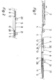
- the track construction train moving in the direction of the arrow is composed of two train sequences.
- the first front wagon sequence which is located in front of the conversion gap 1, has a tractor (not shown) at the front end, a ballast excavator 3 at the rear end, as described for example in CH-PS 597 428, and several for removing the excavated material Transport car 2, as described for example in CH-PS 609 622.
- This sequence of carriages rolls, at least with its rear area, on a provisionally laid work track 4, which was laid within the conversion zone after the tracks to be renewed were removed and preferably consist of track yokes with easily removable iron sleepers.
- the second rear wagon sequence has at the front end a frame wagon 5 with two bogies 6 and 7 and an empty frame 8 installed in between, the length of which is greater than that of a track yoke.
- the rear bogie 7 with its wheels 10 and all the transport wagons belonging to this second wagon series, of which only one transport wagon 9 with buckets 27 is shown in FIG. 1, and the rear tractor (not shown) of this second wagon series roll on the already renovated, newly laid track 11.
- the front bogie 6 with its wheels 12 is in the conversion gap 1, namely at the level of the rear end of the working track 4 lowered onto the cleared bed sole 13, and is at the same height according to FIGS. 1 and 3 with the aid of a lifting device attached raised, on which the rear bogie 7 is located, so that the frame 8 is oriented in the longitudinal direction exactly parallel to the bed sole 13 which runs horizontally in the example considered.
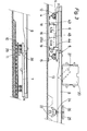
- the lifting device has on each side two hydraulically actuated cylinders 14 and 15, which are articulated with their upper ends to the bogie 6 and with their lower ends to a common support plate 16, which is located next to the working track 4, outside the same, on the bedding base 13 lie on.
- the cylinders 14 and 15 are oriented obliquely to each other.
- a profile 17 is formed on the inside of the rail head of the working track 4 and overlapping it, by means of which the working track 4 is held in an adjusted position when the frame carriage 5 is raised.
- each support plate 16 is also by means of two telescopically displaceable vertical guide tubes 18 and 19 or the like suspended or guided on the bogie 6.
- the frame carriage 5 As soon as the frame carriage 5 has reached its first working position with its front bogie 6, the working track 4 is removed under the frame 8 in a length corresponding to a new track yoke and the front bogie 6 by means of the lifting device 14, 15 to the desired horizontal orientation of the Frame 8 raised.
- the frame 8 If the bed sole 13 has a longitudinal inclination, the frame 8 is oriented parallel to this inclination. In the transverse direction, however, the frame 8 is preferably, as will be explained later, always aligned horizontally, regardless of the respective transverse inclination which the bedding sole 13 has or should have for the purpose of better drainage or in curves.
- the desired inclination of the sole or bedding in the transverse direction can generally be achieved more simply by adjusting the inclination of the dozer blades 22 relative to the horizontally oriented frame 8.
- the bedding base 13 is leveled with the dozer blades 22, optionally in the desired bank, and at the same time compacted with the compressors 23, which are vibrators, by moving the roller frame 25 back and forth along the frame 8.
- the P ortalkräne 20 and 21 filled with sand bucket 27 transported to the frame carriage 5 and emptied through the frame 8, whereupon the sand is leveled and compacted.
- buckets filled with ballast are transported to the frame carriage 5 and emptied through the frame 8, whereupon the ballast is leveled and compacted and then, also with the help of the portal cranes 20 and 21, a new track yoke is brought in and laid.
- the work track 4 in the cleared area of the bed sole 13 only needs to be lowered onto it, without the work track 4 having to be padded or any adjustment or leveling required. This means a significant simplification and acceleration of the renovation work.
- the rear bogie 7 resting on the newly laid track 11 is somewhat lower than the front bogie 6 on the original track 31, because usually the new one Track 11 is initially laid a small amount, for example about 20 cm, lower than it corresponds to its final position; After completion of the renovation work described above, additional ballast is poured between the sleepers of the newly laid track 11, and the sleepers are stuffed to the desired height with the rails being raised accordingly. For this reason, the rear bogie 7 of the frame carriage 5 is equipped with a lifting device which, in the example considered according to FIGS.
- the lifting members of the lifting devices on the front bogie 6 consist of vertically oriented hydraulic cylinders 40 and 41, which form telescopic vertical guides and are hinged at their lower ends to a separate support plate 42 and 43, respectively.
- the two hydraulic cylinders 40 and 41 on each side of the bogie 6 can of course also be articulated on a common support plate, as in the example according to FIG. 3.
- separate support plates can also be provided for each hydraulic cylinder.
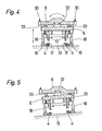
- FIGS. 4 and 5 the frame 8 of the frame carriage 5 is pivotally mounted laterally on the bogies by means of rotating pans 32 in the sense of the curved double arrow according to FIG. 4, of which in FIGS. 4 and 5 the bogie 6 with its wheels 12 is closed see is.
- the exact setting of the transverse position or the inclination relative to the bogies 6 and 7 is carried out with the aid of hydraulically actuated cylinders 33.
- FIG. 5 shows the horizontal orientation of the frame 8 with the bedding base 13 inclined transversely and the bogie 6 correspondingly inclined automatic leveling is facilitated if the frame 8 is always oriented horizontally in the transverse direction and the desired sole or bed inclination in the transverse direction is achieved by a corresponding cross slope of the leveling plates 22.
- the frame 8 can always be oriented exactly parallel to the longitudinal direction of the bed sole 13 in the longitudinal direction, the height of the leveling blades 22 does not need to be changed during the leveling, which simplifies the control effort.
- the described settings of the orientation of the frame carriage 5 and the frame 8 relative to the bogies 6 and 7 can be made either manually or preferably automatically by means of a suitable control system.
- the lifting devices 14, 15 or 40, 41 or 28 on the front or rear bogie can each be actuated and adjusted automatically by a control system which always adjusts the frame 8 in a position parallel to the longitudinal direction of the bed sole 13.
- the control can take place on the basis of measurements of the respective altitudes of the bogies.
- two lights attached to each of the vertical guides 18 and 19 serve barriers 43 and 44 and a reference mirror 45 mounted on the relevant support plate 16 by means of a vertical support 45a, the height of which is set above the support plate 16 in accordance with the intended excavation depth.
- the hydraulic cylinders 14 and 15 are then extended until the reference mirror 45 lies in the beam path 43a or 44a of the light sources of the light barriers 43 and 44 oriented parallel to the bogies 6 and frame 8, respectively, and these due to the reflected light speak to.
- the same measuring and control arrangement can also be provided for the rear bogie 7.
- the height of the bogies 6 and 7 can be measured above the bed base 13 or above the newly laid track 11 using any other known devices, the actual height of the bogie in question being raised to the known, prescribed target height.
- the longitudinal inclination of the frame 8 can be monitored with the aid of an electronic pendulum, the lower bogie being raised until the frame 8 has the desired longitudinal inclination or longitudinal orientation, ie is parallel to the bedding base 13.
- the automatic control can also take place with the aid of at least one laser beam serving as a reference line, the source of which can be located on the bedding bed or on an auxiliary chassis at a distance from the conversion zone.
- the automatic adjustment of the transverse inclination of the frame 8 relative to its bogies 6 and 7 can be carried out, for example, using an electronic pendulum.
- the frame 8 is controlled in such a way that it assumes a predetermined transverse position, in particular always a horizontal position or a correspondingly pivoted position oriented parallel to the transverse inclination of the bed sole 13; in the latter case this is not necessary Swiveling the dozer blades 22 while leveling the sole and the sand deposits.
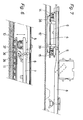
- Figure 6 shows another embodiment of the rear lifting device, which has on each side an arm 35 articulated on the bogie 7 with a support wheel 36 mounted on its lower end, rolling on the rail of the new track 11, and an articulated on the one hand on the bogie 7 and on the other hand on the arm 35 mounted hydraulic cylinder 37.
- the raised frame carriage 5 is supported directly on the rails by the support rollers 36, which according to FIG. 6 are located in the immediate vicinity of the front wheels 10 of the bogie 7.
- FIG. 7 shows a variant of the front lifting device which, on each side, in addition to the two cylinder-piston arrangements 14 and 15 and a common support plate 16 ', has two lowerable pliers 38 and 39 which are mounted on the bogie 6 and which have the rails when the frame carriage 5 is lowered of the working track 4 and lift it up when lifting the frame carriage 5.
- the front lifting device is supported with its hydraulic cylinder dern 47 and 48 on drivable and steerable crawler tracks 46, which can be moved laterally outside the working track 4 on the bed sole 13.
- the bogie 6 does not need to be lowered when the frame carriage 5 advances, so that the front end of the frame carriage can always be kept at the desired height along the entire conversion zone.
- no work track 4 is required for advancing the frame carriage 5, so that it can be removed beforehand in a corresponding length.
- the front bogie 6 has an upper part 6b that can be lifted off the chassis 6a with its wheels 12 and supports the frame 8, and the lifting elements of the lifting device in the form of hydraulically actuated telescopic cylinders 49 and 50 are between the chassis 6a and the upper part of the bogie 6b arranged so that this bogie upper part 6b can be raised to the desired height with the frame 8, while the chassis 6a remains with its wheels 12 on the work rails 4.
- lifting devices 51 and 52 are also provided on both sides of the chassis 6a with support plates 53 and 54 articulated at their lower ends, which can be lowered onto the bed sole 13 and thus carry the main weight of the frame carriage with its implements and onto one Distribute a correspondingly large area of the bed sole.
- the rear bogie can be designed in the same way so that its chassis remains on the newly laid track when the rear end of the frame carriage is raised, in which case lowerable support plates are not required.
- the invention is not based on the described limited examples of management, but includes with regard to the design of the frame carriage, which can also be set up for laying new sleepers and new rails, and its lifting devices and the automatic control of the same, numerous modifications.
Landscapes
- Engineering & Computer Science (AREA)
- Architecture (AREA)
- Civil Engineering (AREA)
- Structural Engineering (AREA)
- Machines For Laying And Maintaining Railways (AREA)
Priority Applications (1)
| Application Number | Priority Date | Filing Date | Title |
|---|---|---|---|
| EP81200045A EP0056497A1 (fr) | 1981-01-15 | 1981-01-15 | Wagon-cadre dans un train pour effectuer l'assainissement du sous-sol des voies de chemin de fer |
Applications Claiming Priority (1)
| Application Number | Priority Date | Filing Date | Title |
|---|---|---|---|
| EP81200045A EP0056497A1 (fr) | 1981-01-15 | 1981-01-15 | Wagon-cadre dans un train pour effectuer l'assainissement du sous-sol des voies de chemin de fer |
Publications (1)
| Publication Number | Publication Date |
|---|---|
| EP0056497A1 true EP0056497A1 (fr) | 1982-07-28 |
Family
ID=8188102
Family Applications (1)
| Application Number | Title | Priority Date | Filing Date |
|---|---|---|---|
| EP81200045A Withdrawn EP0056497A1 (fr) | 1981-01-15 | 1981-01-15 | Wagon-cadre dans un train pour effectuer l'assainissement du sous-sol des voies de chemin de fer |
Country Status (1)
| Country | Link |
|---|---|
| EP (1) | EP0056497A1 (fr) |
Cited By (11)
| Publication number | Priority date | Publication date | Assignee | Title |
|---|---|---|---|---|
| EP1106734A3 (fr) * | 1999-12-07 | 2003-01-08 | Franz Plasser Bahnbaumaschinen-Industriegesellschaft m.b.H. | Procédé et dispositif pour former une voie ferrée |
| DE102009039230A1 (de) * | 2009-08-28 | 2011-03-17 | Zürcher, Ralf | Verfahren zum Erstellen eines Gleiskörpers |
| RU2572485C1 (ru) * | 2014-07-28 | 2016-01-10 | Игорь Анатольевич Пухов | Способ строительства и ремонта бесстыкового пути, рельсошпальная решётка и путеукладочный поезд для его осуществления |
| CN107142797A (zh) * | 2017-06-20 | 2017-09-08 | 宝鸡中车时代工程机械有限公司 | 自行移动式整体道床固化浇注设备 |
| CN107642012A (zh) * | 2017-10-26 | 2018-01-30 | 中铁上海工程局集团有限公司 | 一种城市轨道交通工程新型铺轨机及其施工方法 |
| CN108425294A (zh) * | 2018-05-09 | 2018-08-21 | 廊坊合力天机械设备有限公司 | 自动化轨道排架运输初铺控制装置 |
| CN108442192A (zh) * | 2018-03-24 | 2018-08-24 | 安徽兴宇轨道装备有限公司 | 一种板式道床调板车的顶部活动板 |
| CN108660876A (zh) * | 2018-04-25 | 2018-10-16 | 安徽兴宇轨道装备有限公司 | 一种铺设预制板式道床精调车 |
| CN108755295A (zh) * | 2018-04-25 | 2018-11-06 | 安徽兴宇轨道装备有限公司 | 一种铺设预制板式道床精调车的三维立体调整装置 |
| CN108797237A (zh) * | 2018-04-25 | 2018-11-13 | 安徽兴宇轨道装备有限公司 | 一种用于板式道床精调车的平面精调装置 |
| CN110666753A (zh) * | 2019-10-17 | 2020-01-10 | 安徽瑞铁轨道装备有限公司 | 用于铁路轮对检修平台的可变轨升降装置 |
Citations (3)
| Publication number | Priority date | Publication date | Assignee | Title |
|---|---|---|---|---|
| US4000699A (en) * | 1974-01-29 | 1977-01-04 | Les Fils D'auguste Scheuchzer S.A. | Apparatus for replacement of rail tracks |
| DE2065989B2 (de) * | 1969-10-07 | 1978-11-02 | Franz Plasser Bahnbaumaschinen- Industriegesellschaft Mbh, Wien | Fahrbare Gleisbaumaschine zur Bearbeitung der Schotterbettung |
| DE2913638A1 (de) * | 1978-06-28 | 1980-01-10 | Plasser Bahnbaumasch Franz | Einrichtung zum auswechseln der schienen und schwellen eines gleises |
-
1981
- 1981-01-15 EP EP81200045A patent/EP0056497A1/fr not_active Withdrawn
Patent Citations (3)
| Publication number | Priority date | Publication date | Assignee | Title |
|---|---|---|---|---|
| DE2065989B2 (de) * | 1969-10-07 | 1978-11-02 | Franz Plasser Bahnbaumaschinen- Industriegesellschaft Mbh, Wien | Fahrbare Gleisbaumaschine zur Bearbeitung der Schotterbettung |
| US4000699A (en) * | 1974-01-29 | 1977-01-04 | Les Fils D'auguste Scheuchzer S.A. | Apparatus for replacement of rail tracks |
| DE2913638A1 (de) * | 1978-06-28 | 1980-01-10 | Plasser Bahnbaumasch Franz | Einrichtung zum auswechseln der schienen und schwellen eines gleises |
Cited By (16)
| Publication number | Priority date | Publication date | Assignee | Title |
|---|---|---|---|---|
| EP1106734A3 (fr) * | 1999-12-07 | 2003-01-08 | Franz Plasser Bahnbaumaschinen-Industriegesellschaft m.b.H. | Procédé et dispositif pour former une voie ferrée |
| EP1614805A2 (fr) * | 1999-12-07 | 2006-01-11 | Franz Plasser Bahnbaumaschinen-Industriegesellschaft m.b.H. | Procédé et dispositif pour former une voie ferrée |
| EP1614805A3 (fr) * | 1999-12-07 | 2006-07-26 | Franz Plasser Bahnbaumaschinen-Industriegesellschaft m.b.H. | Procédé et dispositif pour former une voie ferrée |
| DE102009039230A1 (de) * | 2009-08-28 | 2011-03-17 | Zürcher, Ralf | Verfahren zum Erstellen eines Gleiskörpers |
| RU2572485C1 (ru) * | 2014-07-28 | 2016-01-10 | Игорь Анатольевич Пухов | Способ строительства и ремонта бесстыкового пути, рельсошпальная решётка и путеукладочный поезд для его осуществления |
| CN107142797A (zh) * | 2017-06-20 | 2017-09-08 | 宝鸡中车时代工程机械有限公司 | 自行移动式整体道床固化浇注设备 |
| CN107642012A (zh) * | 2017-10-26 | 2018-01-30 | 中铁上海工程局集团有限公司 | 一种城市轨道交通工程新型铺轨机及其施工方法 |
| CN108442192A (zh) * | 2018-03-24 | 2018-08-24 | 安徽兴宇轨道装备有限公司 | 一种板式道床调板车的顶部活动板 |
| CN108660876A (zh) * | 2018-04-25 | 2018-10-16 | 安徽兴宇轨道装备有限公司 | 一种铺设预制板式道床精调车 |
| CN108755295A (zh) * | 2018-04-25 | 2018-11-06 | 安徽兴宇轨道装备有限公司 | 一种铺设预制板式道床精调车的三维立体调整装置 |
| CN108797237A (zh) * | 2018-04-25 | 2018-11-13 | 安徽兴宇轨道装备有限公司 | 一种用于板式道床精调车的平面精调装置 |
| CN108797237B (zh) * | 2018-04-25 | 2023-09-29 | 安徽兴宇轨道装备有限公司 | 一种用于板式道床精调车的平面精调装置 |
| CN108755295B (zh) * | 2018-04-25 | 2023-12-05 | 安徽兴宇轨道装备有限公司 | 一种铺设预制板式道床精调车的三维立体调整装置 |
| CN108660876B (zh) * | 2018-04-25 | 2023-12-05 | 安徽兴宇轨道装备有限公司 | 一种铺设预制板式道床精调车 |
| CN108425294A (zh) * | 2018-05-09 | 2018-08-21 | 廊坊合力天机械设备有限公司 | 自动化轨道排架运输初铺控制装置 |
| CN110666753A (zh) * | 2019-10-17 | 2020-01-10 | 安徽瑞铁轨道装备有限公司 | 用于铁路轮对检修平台的可变轨升降装置 |
Similar Documents
| Publication | Publication Date | Title |
|---|---|---|
| EP0379148B1 (fr) | Procédé et dispositif pour la construction d'une superstructure de la voie sans ballast | |
| EP0255564B1 (fr) | Machine pour remplacer ou rénover respectivement les rails et les traverses d'une voie existante | |
| DE3035910C2 (fr) | ||
| DE2754811C2 (de) | Fahrbare Einrichtung zum Verlegen von Schwellen | |
| DD144578A5 (de) | Einrichtung zum auswechseln der schienen und schwellen eines gleises | |
| DE2818514C2 (fr) | ||
| DE2529135C2 (de) | Gleisbauzug zur Erneuerung einer Eisenbahnstrecke | |
| CH636149A5 (de) | Fahrbare schienenschweissmaschine. | |
| EP0670932B1 (fr) | Machine de pose de voie pour le renouvellement des voies ferrees | |
| DD284067A5 (de) | Fahrbare gleisstopf-, hebe- und richtmaschine zum heben und bzw. oder seitwaertsverschieben eines gleises im weichen- und kreuzungsbereich | |
| EP0056497A1 (fr) | Wagon-cadre dans un train pour effectuer l'assainissement du sous-sol des voies de chemin de fer | |
| EP0771909B1 (fr) | Machine pour le démontage d'une ancienne voie ferrée et l'installation d'une nouvelle voie | |
| EP0342306B1 (fr) | Machine pour ripage latéral d'une voie constituée de rails et de traverses transversales | |
| DE3819717A1 (de) | Kontinuierlich (non-stop) verfahrbare gleisbaumaschine | |
| DE3908007A1 (de) | Gleisbaumaschine mit gleis-stabilisator | |
| DE2840800B1 (de) | Kanalbaumaschine | |
| EP0397956B1 (fr) | Machine de bourrage, mobile de façon continue, comportant un dispositif de charrue | |
| DE3409854A1 (de) | Kontinuierlich (non-stop) verfahrbare gleisstopf-nivellier- und richtmaschine | |
| DE3409853C2 (fr) | ||
| DD154226A5 (de) | Verfahren und vorrichtung zur untergrundsarnierung von eisenbahngleisen | |
| DE2928355C2 (fr) | ||
| EP0619400B1 (fr) | Machine pour travailler un ballast ou un palier de voie | |
| EP0551835B1 (fr) | Dispositif pour la mise en place du sable ou du ballast entre la plate-forme et les rails d'une voie ferrée, et procédé pour remplacer la superstructure de la voie | |
| DE3607245C2 (de) | Verfahren zum Herstellen eines Schotterbettes, insbesondere für Eisenbahngleise auf einem Planum sowie Schotter-Band-Fertiger zur Durchführung des Verfahrens | |
| DE19502450C1 (de) | Gleisgebundene Baumaschine |
Legal Events
| Date | Code | Title | Description |
|---|---|---|---|
| PUAI | Public reference made under article 153(3) epc to a published international application that has entered the european phase |
Free format text: ORIGINAL CODE: 0009012 |
|
| AK | Designated contracting states |
Designated state(s): AT BE CH DE FR GB IT NL |
|
| STAA | Information on the status of an ep patent application or granted ep patent |
Free format text: STATUS: THE APPLICATION IS DEEMED TO BE WITHDRAWN |
|
| 18D | Application deemed to be withdrawn |
Effective date: 19830517 |
|
| RIN1 | Information on inventor provided before grant (corrected) |
Inventor name: SCHEUCHZER, FREDY Inventor name: BUEHLER, FRITZ |