EP0551835B1 - Machine for placing sand or ballast between rails and railway understructure, and method for replacing the railway superstructure - Google Patents
Machine for placing sand or ballast between rails and railway understructure, and method for replacing the railway superstructure Download PDFInfo
- Publication number
- EP0551835B1 EP0551835B1 EP93100197A EP93100197A EP0551835B1 EP 0551835 B1 EP0551835 B1 EP 0551835B1 EP 93100197 A EP93100197 A EP 93100197A EP 93100197 A EP93100197 A EP 93100197A EP 0551835 B1 EP0551835 B1 EP 0551835B1
- Authority
- EP
- European Patent Office
- Prior art keywords
- track
- machine
- ballast
- substructure
- sand
- Prior art date
- Legal status (The legal status is an assumption and is not a legal conclusion. Google has not performed a legal analysis and makes no representation as to the accuracy of the status listed.)
- Expired - Lifetime
Links
Images


Classifications
-
- E—FIXED CONSTRUCTIONS
- E01—CONSTRUCTION OF ROADS, RAILWAYS, OR BRIDGES
- E01B—PERMANENT WAY; PERMANENT-WAY TOOLS; MACHINES FOR MAKING RAILWAYS OF ALL KINDS
- E01B27/00—Placing, renewing, working, cleaning, or taking-up the ballast, with or without concurrent work on the track; Devices therefor; Packing sleepers
- E01B27/04—Removing the ballast; Machines therefor, whether or not additionally adapted for taking-up ballast
-
- E—FIXED CONSTRUCTIONS
- E01—CONSTRUCTION OF ROADS, RAILWAYS, OR BRIDGES
- E01B—PERMANENT WAY; PERMANENT-WAY TOOLS; MACHINES FOR MAKING RAILWAYS OF ALL KINDS
- E01B27/00—Placing, renewing, working, cleaning, or taking-up the ballast, with or without concurrent work on the track; Devices therefor; Packing sleepers
- E01B27/02—Placing the ballast; Making ballastway; Redistributing ballasting material; Machines or devices therefor; Levelling means
- E01B27/022—Placing the ballast; Making ballastway; Redistributing ballasting material; Machines or devices therefor; Levelling means by devices moving on the track with or without spreading or levelling
-
- E—FIXED CONSTRUCTIONS
- E01—CONSTRUCTION OF ROADS, RAILWAYS, OR BRIDGES
- E01B—PERMANENT WAY; PERMANENT-WAY TOOLS; MACHINES FOR MAKING RAILWAYS OF ALL KINDS
- E01B27/00—Placing, renewing, working, cleaning, or taking-up the ballast, with or without concurrent work on the track; Devices therefor; Packing sleepers
- E01B27/02—Placing the ballast; Making ballastway; Redistributing ballasting material; Machines or devices therefor; Levelling means
- E01B27/023—Spreading, levelling or redistributing ballast already placed
-
- E—FIXED CONSTRUCTIONS
- E01—CONSTRUCTION OF ROADS, RAILWAYS, OR BRIDGES
- E01B—PERMANENT WAY; PERMANENT-WAY TOOLS; MACHINES FOR MAKING RAILWAYS OF ALL KINDS
- E01B27/00—Placing, renewing, working, cleaning, or taking-up the ballast, with or without concurrent work on the track; Devices therefor; Packing sleepers
- E01B27/06—Renewing or cleaning the ballast in situ, with or without concurrent work on the track
- E01B27/10—Renewing or cleaning the ballast in situ, with or without concurrent work on the track without taking-up track
- E01B27/105—Renewing or cleaning the ballast in situ, with or without concurrent work on the track without taking-up track the track having been lifted
-
- E—FIXED CONSTRUCTIONS
- E01—CONSTRUCTION OF ROADS, RAILWAYS, OR BRIDGES
- E01B—PERMANENT WAY; PERMANENT-WAY TOOLS; MACHINES FOR MAKING RAILWAYS OF ALL KINDS
- E01B27/00—Placing, renewing, working, cleaning, or taking-up the ballast, with or without concurrent work on the track; Devices therefor; Packing sleepers
- E01B27/12—Packing sleepers, with or without concurrent work on the track; Compacting track-carrying ballast
- E01B27/20—Compacting the material of the track-carrying ballastway, e.g. by vibrating the track, by surface vibrators
-
- E—FIXED CONSTRUCTIONS
- E01—CONSTRUCTION OF ROADS, RAILWAYS, OR BRIDGES
- E01B—PERMANENT WAY; PERMANENT-WAY TOOLS; MACHINES FOR MAKING RAILWAYS OF ALL KINDS
- E01B2203/00—Devices for working the railway-superstructure
- E01B2203/01—Devices for working the railway-superstructure with track
- E01B2203/015—Devices for working the railway-superstructure with track present but lifted
-
- E—FIXED CONSTRUCTIONS
- E01—CONSTRUCTION OF ROADS, RAILWAYS, OR BRIDGES
- E01B—PERMANENT WAY; PERMANENT-WAY TOOLS; MACHINES FOR MAKING RAILWAYS OF ALL KINDS
- E01B2203/00—Devices for working the railway-superstructure
- E01B2203/10—Track-lifting or-lining devices or methods
Definitions
- the invention relates to a machine for installing sand or crushed stone between the substructure and the track with a bogie at the front in the working direction and a rear bogie, with a bridge mounted on the bogies, with lifting devices for the track, with conveyor devices, with distribution devices and compression devices and a method for converting the superstructure, possibly also the substructure or parts of the substructure of a web body.
- ballast belt In the area of the rear bogie, a ballast belt is provided which releases a layer of ballast on the compacted sand, which is compacted by means of its own compressor devices.
- Another version of the machine is designed such that it consists of a work vehicle and a special one Transport vehicle exists.
- the rear end of the bridge is virtually saddled onto the transport vehicle according to the working direction of the machine.
- the bogie arranged in this area of the bridge is also raised, so that the length of the track grate to be raised is increased so as not to exceed the permissible bending stress of the track grate.
- the lifting height of the platform is dependent on this, spanned by the bridge and limited by the length of the bogies. This restricted lifting height disadvantageously limits the space for the arrangement of the work equipment, such as the excavation equipment for the old bed or the leveling and compacting equipment for the sand.
- the excavation device which consists of a clearing chain with an endless ballast chain, is height-adjustable on the bridge.
- a conveyor belt arrangement adjoins the excavation device and serves to remove the bedding material that has been taken up. The bedding material is loaded onto the transport devices for bulk goods moving in the working direction in front of the work vehicle.
- a separate conveyor belt arrangement for sand and a separate conveyor belt arrangement for ballast are arranged in the work area of the work vehicle.
- the conveying directions of the conveyor belt arrangement for sand or for gravel correspond to the working direction of the work vehicle.
- the conveyor belt arrangements are located essentially in the inner area of the bridge.
- the conveyor belt arrangement for sand has a fixed conveyor belt.
- a pivotable individual conveyor belt is reached by means of a chute.
- the discharge end of this individual conveyor belt is located between the clearing chain receiving part and the leveling device guided under the track, but above the track. Furthermore, the position of the pivotable individual conveyor belt is limited by the overhanging clearing chain receiving part.
- the conveyor belt arrangement for ballast consists of a further individual conveyor belt, which is pivotably arranged under the fixed conveyor belt for sand, the discharge end of which ends above a chute-like outlet opening.
- a rail tunnel and a plow arrangement for distributing the ballast are assigned to the outlet opening.
- the plow arrangement in turn is followed either by a leveling device for crushed stone or a tamping unit.
- the conveyor belt arrangements for sand and gravel begin under the respective bunker, which is located on the transport vehicle following the work vehicle and is required for the intermediate storage of sand and gravel.
- the machine has a track lifting and holding device directly behind the plow arrangement.
- the leveling device can be swiveled in laterally below the track and is articulated in a height-adjustable manner on the support frame.
- the known machine thus realizes the lifting of the old ballast bed, the input of a new one in one work process - with the track slightly raised Sand layer, compacting the sand layer, building a new ballast layer, compacting the ballast layer and then laying down the track grate.
- This known machine has a very large overall length due to the many work steps that are carried out with this machine, and the bridge is - because of the large number of work steps - formed in two parts with a middle support and lifting device.
- a major disadvantage of this machine is the complex structure.
- the low working speed of this machine is particularly disadvantageous.
- the interplay of the work facilities must always be 100% guaranteed, otherwise the desired performance will not be achieved.
- Can e.g. the full excavation of the ballast bed and possibly still part of the formation can not be carried out with a work trip, then the other work equipment must be put out of operation during another work trip over the same track section.
- the object of the invention is therefore to develop a machine of the type mentioned in such a way that it has a simple and robust structure at an increased working speed, and a method for converting the superstructure of a track body preferably for the purpose of increasing the maximum speed previously permitted for the track body to accomplish.
- the machine must be able to be classified into the system of the track construction machine known per se, such as ballast bed cleaning machines, track tamping machines and transport devices.
- the working field is located between a front and a rear lifting device for the track according to the working direction of the machine.
- the bedding material, sand or gravel is continuously conveyed on a conveyor line of the machine to the material installation area between the substructure and the track.
- the conveyor line essentially consists of a first rigid, ie non-pivotably arranged and at least a second conveyor device which can be pivoted over the area of the superstructure, the bedding material being conveyed in the working direction of the machine and being delivered to the material installation area, but at changed execution the bedding material is conveyed against the working direction to the material installation area.
- the first conveyor runs from the rear bogie to about the middle of the bridge.
- a stationary transfer device in particular a filling funnel, is arranged under the discharge end of this conveying device, to which the pivotable second conveying device connects.
- the working speed can be advantageously increased by arranging more than one swiveling conveying device and, if appropriate, the associated and particularly arranged pouring channels in the material installation area.
- the effect of the second conveyor which acts as a distribution device, can be improved by arranging an additional conveyor, which can be pivoted transversely to the working direction, under the hopper.
- the additional conveyor can be pivoted at its front end by means of a swivel arm.
- the sand or the ballast is preferably continuously conveyed to the material installation area by endless conveyor belts, so that the sand or the ballast each form a quasi-homogeneous layer.
- the layers are sharply separated from one another and form a high-quality superstructure. It is particularly advantageous that other protective layers, for example made of setting mixtures or foils, can also be introduced before the sand or the ballast is introduced.
- all formation levels can be leveled and compacted according to the requirements for the substructure and superstructure.
- a height-adjustable leveling plow is arranged opposite the working direction after the discharge end of the pivoting conveyor belt, which runs across the working width and the tip of the leveling plow is designed as a joint and / or has two telescopic sections so that the working width can be adjusted.
- the leveling plow is height-adjustable on hydraulically adjustable arms attached to the bridge.
- a receiver is provided which responds to signals from a direction finding device, which is set up in front of the machine and points towards the receiver in the direction of the track.
- the level of the leveling plow can be adjusted manually, if necessary also automatically, depending on the direction-finding signals received by the receiver, in order to plan the desired height of the material, either sand or gravel.
- the compressor device following the leveling device according to the working direction of the machine is particularly preferably equipped with a plurality of spaced-apart soil compactors, which are preferably arranged in parallel rows with a fixed gap offset transversely to the working direction and in this way compact over a large area at high working speed.
- the compressor device is arranged on the arms carrying the leveling device or on separate arms on the bridge and can be pivoted from a lower, forward-facing working position into a rearward-facing upper transport position.
- Loose entrainment of the compressor device or suspension of the pre-seal device on a guide advantageously utilizes an inherent movement of the compressor device with respect to the machine in the work area.
- the working direction of the machine is cut by a continuously curved or an almost linearly oscillating working direction of the compressor device or the linearly oscillating working direction runs parallel to the working direction of the machine.
- the relative movements of the soil compactors in or against the working direction of the machine are not affected by the working speed of the machine.
- Embankment compactors are particularly preferably provided on brackets on both sides of the machine, which additionally compact the slopes of the superstructure and ensure that the desired track body profile is maintained.
- the embankment compactors are particularly in the working direction arranged immediately in front of the rear bogie.
- Each slope compactor contains at least one surface compactor.
- the front bogie of the machine is part of a drive car.
- the bridge rests on a frame of the drive car over its bogie.
- the drive car may contain further bogies.
- FIG. 1 to 4 show a machine for the installation of sand 5 or ballast between a formation 1 and a track 2.
- a pivotable conveyor belt 42, a chute 40 lying transversely to the working direction, which is located above the material installation area, and a compacting device 30 are arranged in order to remove sand 5 or ballast from behind the rear Bogie 4 coupled transport device, ie to be taken up by the conveyor belt 100, to be conveyed by means of a first conveyor belt 14 to approximately the middle of the bridge 6, to be transferred to the pivotable second conveyor belt 42 via a stationary funnel 13 and to be distributed by means of the latter, then to be leveled and / or compacted.
- the bridge 6 is self-supporting over its entire length and has a rear lifting device 20 for the track 2 in the working direction in front of the rear bogie 4, which is attached to the bridge 6 by hydraulic lifting arms and is known Way with lifting rollers 21 under the rail heads.
- a compactor device 30 which consists of two rows 32 and 34 of spaced-apart soil compactors 36 which run transversely to the working direction, the soil compactors 36 of the second row 34 having a transverse offset with respect to the soil compactors 36 of the first row 32 and thereby being set to a gap.
- the relative movement of the soil compactors compared to the machine is zero.
- FIG. 4 shows a further exemplary embodiment of the compressor device 30, which in the embodiment shown consists of two guides 38 arranged essentially in the longitudinal direction of the machine and two soil compactors 36 movably arranged thereon.
- the guides 38 are articulated at one end 38a to the leveling device 60, the other end 38b is freely movable.
- the soil compactors 36 are displaceably guided along the guides 38 and move during operation along these guides when moving parts, for example a bottom plate subjected to vibration, compact the sand or gravel underneath.
- actuating cylinder / piston arrangements 39 are provided, which allow the guides 38 to be pivoted about their articulation point 38a.
- the vibration of the base plate is generated by an eccentric rotating in the base compactor, which at the same time brings about the longitudinal displacement of the base compactor along the guide 38. This ensures that the soil compactors 36 work with a movement relative to the entire machine when compacting, while compacting sand prevents the soil compactors 36 from working too long in the same place and loosening the compacted sand underneath again.
- FIG. 4 Another advantage of the embodiment according to FIG. 4 is that the guides 38 can be set slightly outwards against the longitudinal direction or working direction of the machine, depending on the width of the track bed to be compacted, so that the working width of the compressor device 30 Width of the track bed can be adjusted. In addition, it is avoided that transverse troughs are formed, since the soil compactors 36 essentially overlap in the longitudinal direction of the machine.
- a known vibrating screed can be used instead of surface compactors 36 especially for ballast compaction.
- a leveling device 60 is designed as a leveling plow, which extends over the entire working width of the machine, the plow tip of which is designed as a joint and which consists of at least two telescopic horizontal sections 62 and 64 which are attached to arms 66 at their ends are, which in turn are articulated on the bridge 6.
- the compressor device 30 is also seated on the arms 66.
- the leveling plow is height adjustable. There is a receiver 70 above the leveling plow, which responds to signals from a direction finder 72, which is set up sufficiently far in front of the machine in the working direction and determines the respective height of the sand or gravel layer to be applied. Depending on the direction-finding signals received, the leveling plow can be adjusted manually or automatically to an appropriate height.
- a pivotable second conveyor belt 42 is arranged above the leveling plow and the compressor device 30, the discharge end of which - in the working direction - ends before the leveling plow via a pouring trough 40 arranged transversely to the working direction of the machine.
- the pivotable conveyor belt 42 By means of the pivotable conveyor belt 42, the bedding material to be dispensed, sand 5 or ballast, is distributed according to the required width of the formation protection layer or the ballast bed, then leveled by the leveling plow and then compacted by the compressor device 30.
- the chute 40 guides the bedding material into the sleeper compartments.
- a front track lifting device 22 which is also arranged on the bridge 6 via hydraulically actuated lifting arms and engages under the rail heads by means of lifting rollers 21.
- the receptacles for surface compactor 36 can be swung out in such a way that the embankment of the filled and leveled sand or gravel layer can be compacted with a surface compactor 36 arranged at the end of these receptacles.
- the front bogie 3 of the machine, on which the front end of the bridge 6 is supported, is at the same time the rear bogie of the drive car 90, which - in the embodiment shown, compare in particular FIG. 2 - has another bogie 96 of its own and in addition to the Drive units also includes the control units for the machine.
- the operation of the machine during work travel can include from the cabin 15 arranged on the bridge 6.
- the working devices of the machine can be locked in the respective transport position below the bridge 6.
- the compact arrangement of the work equipment under the bridge 6, in particular the compact arrangement of the pouring channel 40, the leveling plow and the compacting device 30, enables the high-quality installation of a level protection layer made of sand 5 and - in a second operation - a corresponding ballast bed is deposited on this level protection layer , in particular because of the advantageously arranged compressor device 30, a high working speed of the individual operations can be achieved.
- a method for converting the superstructure of a web body is described with reference to FIGS. 5 to 9.
- the track 2 is picked up and the old ballast 50 is removed up to the old planum 1a.
- the old ballast 50 is transported away in the working direction.
- Track 2 is placed on the old planum 1a.
- the track 2 is raised and a formation protection layer, preferably sand 5, is introduced.
- Track 2 is placed on the formation protection layer.
- the track 2 is again picked up and the ballast is inserted and the track 2 on the or. stored in the gravel.
- any required layer thickness of the superstructure of a web body to be renovated can be absorbed.
- the sand 5 After the sand 5 has been introduced, it is generally leveled and / or compacted.
- the method allows the deeper-lying partial layer to be leveled and / or compacted before the introduction of a partial layer of sand 5, the surface of the partial layer possibly being loosened beforehand.
- the introduction of partial layers guarantees the compaction of sand 5 down to the bottom of the formation protection layer. If necessary, the sand 5 must be moistened before it is introduced or compacted.
Abstract
Description
Die Erfindung betrifft eine Maschine zum Einbau von Sand oder Schotter zwischen dem Unterbau und dem Gleis mit einem in Arbeitsrichtung vorderen Drehgestell und einem hinteren Drehgestell, mit einer auf den Drehgestellen gelagerten Brücke, mit Hebeeinrichtungen für das Gleis, mit Fördereinrichtungen, mit Verteileinrichtungen und Verdichtereinrichtungen und ein Verfahren zum Umbau des Oberbaues, gegebenenfalls auch des Unterbaus oder von Teilen des Unterbaus eines Bahnkörpers.The invention relates to a machine for installing sand or crushed stone between the substructure and the track with a bogie at the front in the working direction and a rear bogie, with a bridge mounted on the bogies, with lifting devices for the track, with conveyor devices, with distribution devices and compression devices and a method for converting the superstructure, possibly also the substructure or parts of the substructure of a web body.
Es ist eine gleisfahrbare Maschine zur Herstellung einer zwischen Planum und Schotterbett verlaufenden Sandschicht gemäß DE-PS 32 27 725 bekannt, bei der eine zweiteilige Brücke Verwendung findet, deren beide Brückenteile an einem Drehbolzen gelenkig miteinander verbunden sind und an diesem Gelenk über ein mittleres Drehgestell auf dem Gleisrost abgestützt werden. Bei dieser bekannten Maschine ist dieses Gelenk der Brücke als eine Hebeeinrichtung ausgebildet, wobei ein Verschwenken der beiden Brückenteile den Gelenkpunkt und damit auch das mittlere Drehgestell und den darunter befindlichen Gleisrost mittels am mittleren Drehgestell befestigter Hebeeinrichtungen anhebt. Zwischen dieser speziellen Hebeeinrichtung und dem hinteren Drehgestell befindet sich bei der bekannten Maschine eine Schotteraushubeinrichtung, welche den alten Schotter unter dem Gleisrost aushebt und in Arbeitsrichtung nach vorn über Förderbänder abtransportiert. Nach der Aushubeinrichtung ist zwischen zwei Gleishebezangen eine Verteilereinrichtung und eine Verdichtereinrichtung für den aufgeschütteten Sand vorgesehen.There is a track-traveling machine for producing a sand layer running between the subgrade and the ballast bed according to DE-PS 32 27 725, in which a two-part bridge is used, the two bridge parts of which are articulated on a pivot pin and on this joint via a central bogie the track grate are supported. In this known machine, this joint of the bridge is designed as a lifting device, wherein pivoting of the two bridge parts raises the point of articulation and thus also the middle bogie and the track grating underneath by means of lifting devices attached to the middle bogie. Between this special lifting device and the rear bogie, there is a ballast excavation device in the known machine, which lifts the old ballast under the track grate and transports it forward in the working direction via conveyor belts. After the excavation device, a distributor device and a compressor device for the piled-up sand are provided between two track lifting tongs.
Im Bereich des hinteren Drehgestells ist ein Schotterband vorgesehen, welches auf den verdichteten Sand eine Schotterschicht abgibt, die mittels eigener Verdichtereinrichtungen verdichtet wird.In the area of the rear bogie, a ballast belt is provided which releases a layer of ballast on the compacted sand, which is compacted by means of its own compressor devices.
Eine weitere Ausführung der Maschine ist derart gestaltet, daß diese aus einem Arbeitsfahrzeug und einem speziellen Transportfahrzeug besteht. Für die Arbeitsfahrt wird gemäß der Arbeitsrichtung der Maschine das hintere Ende der Brücke auf das Transportfahrzeug quasi aufgesattelt. Dabei wird das in diesem Bereich der Brücke angeordnete Drehgestell mit angehoben, so daß die Länge des zu hebenden Gleisrostes vergrößert wird, um die zulässige Biegespannung des Gleisrostes nicht zu überschreiten. Von dieser, von der Brücke überspannten und durch die die Drehgestelle begrenzten Länge des hebbaren Gleisrostes ist die Hubhöhe desselben abhängig. Diese eingeschränkte Hubhöhe begrenzt in jedem Fall nachteilig den Freiraum für die Anordnung der Arbeitseinrichtungen, wie z.B. die Aushubeinrichtung für die Altbettung oder die Planier- und Verdichtereinrichtungen für den Sand. Die Aushubeinrichtung, die aus einer Räumkettenaufnahme mit endloser Schotteraufnahmekette besteht, ist höhenverstellbar an der Brücke angeordnet. An die Aushubeinrichtung schließt eine Förderbandanordnung an, die zum Abtransport des aufgenommenen Bettungsmaterials dient. Das Bettungsmaterial wird auf die in Arbeitsrichtung vor dem Arbeitsfahrzeug fahrenden Transporteinrichtungen für Schüttgut verladen. Nach der Aushubeinrichtung ist jeweils eine eigene Förderbandanordnung für Sand und eine eigene Förderbandanordnung für Schotter im Arbeitsbereich des Arbeitsfahrzeuges angeordnet.Another version of the machine is designed such that it consists of a work vehicle and a special one Transport vehicle exists. For the work journey, the rear end of the bridge is virtually saddled onto the transport vehicle according to the working direction of the machine. The bogie arranged in this area of the bridge is also raised, so that the length of the track grate to be raised is increased so as not to exceed the permissible bending stress of the track grate. The lifting height of the platform is dependent on this, spanned by the bridge and limited by the length of the bogies. This restricted lifting height disadvantageously limits the space for the arrangement of the work equipment, such as the excavation equipment for the old bed or the leveling and compacting equipment for the sand. The excavation device, which consists of a clearing chain with an endless ballast chain, is height-adjustable on the bridge. A conveyor belt arrangement adjoins the excavation device and serves to remove the bedding material that has been taken up. The bedding material is loaded onto the transport devices for bulk goods moving in the working direction in front of the work vehicle. After the excavation device, a separate conveyor belt arrangement for sand and a separate conveyor belt arrangement for ballast are arranged in the work area of the work vehicle.
Die Förderrichtungen der Förderbandanordnung für Sand oder der für Schotter entsprechen der Arbeitsrichtung des Arbeitsfahrzeuges. Die Förderbandanordnungen befinden sich im wesentlichen im inneren Bereich der Brücke.The conveying directions of the conveyor belt arrangement for sand or for gravel correspond to the working direction of the work vehicle. The conveyor belt arrangements are located essentially in the inner area of the bridge.
Die Förderbandanordnung für Sand weist ein fest angeordnetes Föderband auf. Mittels einer Schurre wird ein verschwenkbares Einzelförderband erreicht.The conveyor belt arrangement for sand has a fixed conveyor belt. A pivotable individual conveyor belt is reached by means of a chute.
Das Abwurfende dieses Einzelförderbandes befindet sich zwischen dem Räumkettenaufnahmeteil und der unter dem Gleis geführten Planiereinrichtung, aber oberhalb des Gleises. Weiterhin ist die Lage des verschwenkbaren Einzelförderbandes durch das überkragende Räumkettenaufnahmeteil nach oben hin begrenzt.The discharge end of this individual conveyor belt is located between the clearing chain receiving part and the leveling device guided under the track, but above the track. Furthermore, the position of the pivotable individual conveyor belt is limited by the overhanging clearing chain receiving part.
Die Förderbandanordnung für Schotter besteht aus einem weiteren, unter dem fest angeordneten Förderband für Sand verschwenkbar angeordneten Einzelförderband, dessen Abwurfende über einer schurrenartigen Auslaßöffnung endet. Der Auslaßöffnung ist ein Schienentunnel und eine Pfluganordnung zum Verteilen des Schotters zugeordnet. Der Pfluganordnung wiederum ist entweder eine Planiereinrichtung für Schotter oder ein Stopfaggregat nachgeordnet. Die Förderbandanordnungen für Sand und Schotter beginnen unter dem jeweiligen Bunker, der sich auf dem dem Arbeitsfahrzeug nachfolgenden Transportfahrzeug befindet und für die Zwischenlagerung von Sand und Schotter erforderlich ist.The conveyor belt arrangement for ballast consists of a further individual conveyor belt, which is pivotably arranged under the fixed conveyor belt for sand, the discharge end of which ends above a chute-like outlet opening. A rail tunnel and a plow arrangement for distributing the ballast are assigned to the outlet opening. The plow arrangement in turn is followed either by a leveling device for crushed stone or a tamping unit. The conveyor belt arrangements for sand and gravel begin under the respective bunker, which is located on the transport vehicle following the work vehicle and is required for the intermediate storage of sand and gravel.
Die Maschine weist unmittelbar hinter der Pfluganordnung eine Gleishebe- und -haltevorrichtung auf. Die Planiereinrichtung ist unterhalb des Gleises seitlich einschwenkbar angeordnet und am Trägerrahmen höhenverstellbar angelenkt.The machine has a track lifting and holding device directly behind the plow arrangement. The leveling device can be swiveled in laterally below the track and is articulated in a height-adjustable manner on the support frame.
Mit der beschriebenen Maschine ist ein Verfahren zum Umbau von Gleisen möglich, das im wesentlichen durch die Funktion der Maschine bestimmt wird.With the machine described, a method for converting tracks is possible, which is essentially determined by the function of the machine.
Die bekannte Maschine verwirklicht also in einem Arbeitsvorgang - bei minimal angehobenem Gleis - das Ausheben des alten Schotterbettes, das Eingeben einer neuen Sandschicht, das Verdichten der Sandschicht, den Aufbau einer neuen Schotterschicht, das Verdichten der Schotterschicht sowie das anschließende Ablegen des Gleisrostes.The known machine thus realizes the lifting of the old ballast bed, the input of a new one in one work process - with the track slightly raised Sand layer, compacting the sand layer, building a new ballast layer, compacting the ballast layer and then laying down the track grate.
Diese bekannte Maschine besitzt aufgrund der vielen Arbeitsgänge, welche mit dieser Maschine verwirklicht werden, eine sehr große Baulänge, und die Brücke ist - wegen der großen Anzahl an Arbeitsgängen - zweiteilig mit einer mittleren Stütz- und Hebeeinrichtung ausgebildet. Ein wesentlicher Nachteil dieser Maschine ist also der komplexe Aufbau.This known machine has a very large overall length due to the many work steps that are carried out with this machine, and the bridge is - because of the large number of work steps - formed in two parts with a middle support and lifting device. A major disadvantage of this machine is the complex structure.
Neben dem komplexen Aufbau ist insbesondere die geringe Arbeitsgeschwindigkeit dieser Maschine nachteilig. Das Zusammenspiel der Arbeitseinrichtungen muß stets 100%ig gewährleistet sein, da sonst die angestrebte Leistungsfähigkeit nicht erreicht wird. Kann z.B. der Vollaushub des Schotterbettes und eventuell noch ein Teil des Planums nicht mit einer Arbeitsfahrt durchgeführt werden, dann müssen bei einer weiteren Arbeitsfahrt über den gleichen Gleisabschnitt die anderen Arbeitseinrichtungen außer Betrieb gesetzt werden.In addition to the complex structure, the low working speed of this machine is particularly disadvantageous. The interplay of the work facilities must always be 100% guaranteed, otherwise the desired performance will not be achieved. Can e.g. the full excavation of the ballast bed and possibly still part of the formation can not be carried out with a work trip, then the other work equipment must be put out of operation during another work trip over the same track section.
Ein analoges Problem ergibt sich, wenn eine Arbeitseinrichtung ausfällt, dann stehen die anderen Arbeitseinrichtungen auch.An analogous problem arises if one work facility fails, the other work facilities also stand.
Aufgabe der Erfindung ist es daher, eine Maschine der eingangs genannten Art derart weiterzubilden, daß sie einen einfachen und robusten Aufbau bei einer vergrößerten Arbeitsgeschwindigkeit aufweist, und ein Verfahren zum Umbau des Oberbaues eines Bahnkörpers vorzugsweise zum Zwecke der Erhöhung der für den Bahnkörper bisher zugelassenen Höchstgeschwindigkeit zu schaffen.The object of the invention is therefore to develop a machine of the type mentioned in such a way that it has a simple and robust structure at an increased working speed, and a method for converting the superstructure of a track body preferably for the purpose of increasing the maximum speed previously permitted for the track body to accomplish.
Die Maschine muß sich in das System der an sich bekannten Gleisbaumaschine, wie Schotterbettreinigungsmaschinen, Gleisstopfmaschinen und Transporteinrichtungen, einordnen lassen.The machine must be able to be classified into the system of the track construction machine known per se, such as ballast bed cleaning machines, track tamping machines and transport devices.
Diese Aufgabe wird bei der Maschine gemäß dem Oberbegriff des Hauptanspruches erfindungsgemäß dadurch gelöst, daß die Brücke über die gesamte Länge selbsttragend, also gelenkfrei ausgebildet ist und über ihre Länge keine weitere Abstützung erfährt. Dies ist ein wesentlicher Vorteil, da die selbsttragende Brücke die Basis für einen besonders einfachen und robusten Aufbau der Maschine bildet.This object is achieved according to the invention in the machine according to the preamble of the main claim in that the bridge is self-supporting over the entire length, that is to say is free of joints, and is not supported any further over its length. This is a major advantage, since the self-supporting bridge forms the basis for a particularly simple and robust construction of the machine.
Vorteilhaft ist außerdem, daß sich das Arbeitsfeld gemäß der Arbeitsrichtung der Maschine zwischen einer vorderen und einer hinteren Hebeeinrichtung für das Gleis befindet. Das Bettungsmaterial, Sand oder Schotter, wird kontinuierlich auf einer Förderstraße der Maschine zum Materialeinbaubereich zwischen Unterbau und Gleis gefördert. Mit der erfindungsgemäßen Maschine wird somit jeweils ein Arbeitsgang - nur das Einbringen von Sand oder nur das Einbringen von Schotter einschließlich der damit zusammenhängenden Arbeiten - realisiert, dieser wird jedoch mit einer hohen Arbeitsgeschwindigkeit durchgeführt.It is also advantageous that the working field is located between a front and a rear lifting device for the track according to the working direction of the machine. The bedding material, sand or gravel, is continuously conveyed on a conveyor line of the machine to the material installation area between the substructure and the track. With the machine according to the invention, one work step - only the introduction of sand or only the introduction of ballast including the work associated therewith - is thus implemented, but this is carried out at a high working speed.
Die Förderstraße besteht im wesentlichen aus einer ersten starren, d.h. nicht schwenkbar angeordneten und mindestens einer zweiten über den Bereich des Oberbaus verschwenkbaren Fördereinrichtung, wobei das Bettungsmaterial in Arbeitsrichtung der Maschine gefördert und an den Materialeinbaubereich abgegeben wird, aber bei veränderter Ausführung das Bettungsmaterial entgegen der Arbeitsrichtung zum Materialeinbaubereich gefördert wird.The conveyor line essentially consists of a first rigid, ie non-pivotably arranged and at least a second conveyor device which can be pivoted over the area of the superstructure, the bedding material being conveyed in the working direction of the machine and being delivered to the material installation area, but at changed execution the bedding material is conveyed against the working direction to the material installation area.
Die erste Fördereinrichtung verläuft vom hinteren Drehgestell bis etwa in den mittleren Bereich der Brücke.The first conveyor runs from the rear bogie to about the middle of the bridge.
Unter dem Abwurfende dieser Fördereinrichtung ist eine stationäre Übergabeeinrichtung, insbesondere ein Fülltrichter, angeordnet, an die die schwenkbare zweite Fördereinrichtung anschließt. Durch die Anordnung von mehr als einer schwenkbaren Fördereinrichtung und gegebenenfalls den zugeordneten und im besonderen angeordneten Schüttrinnen im Materialeinbaubereich läßt sich die Arbeitsgeschwindigkeit vorteilhaft erhöhen.A stationary transfer device, in particular a filling funnel, is arranged under the discharge end of this conveying device, to which the pivotable second conveying device connects. The working speed can be advantageously increased by arranging more than one swiveling conveying device and, if appropriate, the associated and particularly arranged pouring channels in the material installation area.
Die Wirkung der als Verteileinrichtung wirkenden zweiten Fördereinrichtung kann durch die Anordnung einer zusätzlichen, quer zur Arbeitsrichtung schwenkbaren Fördereinrichtung unter dem Fülltrichter verbessert werden. Dabei kann die zusätzliche Fördereinrichtung an ihrem vorderen Ende mittels eines Schwenkarmes geschwenkt werden.The effect of the second conveyor, which acts as a distribution device, can be improved by arranging an additional conveyor, which can be pivoted transversely to the working direction, under the hopper. The additional conveyor can be pivoted at its front end by means of a swivel arm.
Der Sand oder der Schotter wird bevorzugt durch endlose Förderbänder kontinuierlich zum Materialeinbaubereich gefördert, so daß der Sand oder der Schotter jeweils eine quasi homogene Schicht bilden. Die Schichten sind scharf voneinander getrennt und bilden einen hochwertigen Oberbau. Von besonderem Vorteil ist es, daß vor dem Einbringen des Sandes oder des Schotters auch andere Schutzschichten, z.B. aus abbindenden Gemischen oder Folien, eingebracht werden können.The sand or the ballast is preferably continuously conveyed to the material installation area by endless conveyor belts, so that the sand or the ballast each form a quasi-homogeneous layer. The layers are sharply separated from one another and form a high-quality superstructure. It is particularly advantageous that other protective layers, for example made of setting mixtures or foils, can also be introduced before the sand or the ballast is introduced.
Durch die wahlweise Anordnung von Planiereinrichtungen und/oder der Verdichtereinrichtung vor und/oder nach einem Materialeinbaubereich lassen sich alle Planumsebenen gemäß den Anforderungen an Unterbau und Oberbau qualitätsgerecht ebnen und verdichten.Through the optional arrangement of leveling devices and / or the compressor device before and / or after a material installation area, all formation levels can be leveled and compacted according to the requirements for the substructure and superstructure.
Durch eine weitere vorteilhafte Ausgestaltung der Maschine, d.h. durch Anordnung einer Auflockerungseinrichtung vor der Planiereinrichtung, wird erreicht, daß ungleichmäßige Vorverfestigungen, insbesondere der Planumsschutzschicht, die durch das Ablegen des Gleises auf dem Planum bzw. den jeweiligen Planumsschutzschichten eintreten können, beseitigt werden.Through a further advantageous embodiment of the machine, i.e. by arranging a loosening device in front of the leveling device, it is achieved that uneven pre-consolidations, in particular the formation protection layer, which can occur due to the laying of the track on the formation or the respective formation protection layers, are eliminated.
Besonders bevorzugt ist entgegen der Arbeitsrichtung nach dem Abgabeende des schwenkbaren Förderbandes ein höhenverstellbarer Planierpflug angeordnet, welcher quer über die Arbeitsbreite verläuft und wobei die Spitze des Planierpfluges als Gelenk ausgebildet ist und/oder zwei teleskopierbare Abschnitte aufweist, so daß die Arbeitsbreite einstellbar ist. Der Planierpflug ist an hydraulisch verstellbaren, an der Brücke befestigten Armen höhenverstellbar angeordnet. Im Bereich des Planierpfluges, und zwar über dem Planierpflug, ist ein Empfänger vorgesehen, der auf Signale einer Peileinrichtung anspricht, die vor der Maschine aufgestellt ist und in Gleisrichtung gegen den Empfänger peilt.Particularly preferably, a height-adjustable leveling plow is arranged opposite the working direction after the discharge end of the pivoting conveyor belt, which runs across the working width and the tip of the leveling plow is designed as a joint and / or has two telescopic sections so that the working width can be adjusted. The leveling plow is height-adjustable on hydraulically adjustable arms attached to the bridge. In the area of the leveling plow, namely above the leveling plow, a receiver is provided which responds to signals from a direction finding device, which is set up in front of the machine and points towards the receiver in the direction of the track.
Die Stellhöhe des Planierpfluges ist in Abhängigkeit von den vom Empfänger empfangenen Peilsignalen manuell, gegebenenfalls auch automatisch einstellbar, um die gewünschte Höhe des abgegebenen Materials, entweder Sand oder Schotter, einzuplanieren.The level of the leveling plow can be adjusted manually, if necessary also automatically, depending on the direction-finding signals received by the receiver, in order to plan the desired height of the material, either sand or gravel.
Besonders bevorzugt ist die gemäß der Arbeitsrichtung der Maschine der Planiereinrichtung nachfolgende verdichtereinrichtung mit mehreren beabstandeten Bodenverdichtern ausgerüstet, die bevorzugt in parallelen Reihen mit festem Lückenversatz quer zur Arbeitsrichtung angeordnet sind und auf diese Weise großflächig mit hoher Arbeitogeschwindigkeit verdichten.The compressor device following the leveling device according to the working direction of the machine is particularly preferably equipped with a plurality of spaced-apart soil compactors, which are preferably arranged in parallel rows with a fixed gap offset transversely to the working direction and in this way compact over a large area at high working speed.
Die Verdichtereinrichtung ist an den die Planiereinrichtung tragenden Armen oder an separaten Armen an der Brücke angeordnet und läßt sich aus einer unteren, nach vorn gerichteten Arbeitsstellung in eine nach hinten gerichtete obere Transportlage verschwenken.The compressor device is arranged on the arms carrying the leveling device or on separate arms on the bridge and can be pivoted from a lower, forward-facing working position into a rearward-facing upper transport position.
Durch ein loses Mitführen der Verdichtereinrichtung oder eine Aufhängung der Vordichtereinrichtung an einer Führung wird eine Eigenbewegung der Verdichtereinrichtung gegenüber der Maschine im Arbeitsfeld vorteilhaft ausgenutzt. Zur Erzielung einer gleichmäsigen Verdichtung des Planums oder der Planumsschutzschicht wird die Arbeiterichtung der Maschine von einer stetig bogenförmigen oder einer nahezu linear oszillierenden Arbeitsrichtung der Verdichtereinrichtung geschnitten oder die linear oszillierende Arbeitsrichtung verläuft parallel zur Arbeitsrichtung der Maschine. Die Relativbewegungen der Bodenverdichter in oder entgegen der Arbeitsrichtung der Maschine werden von der Arbeitsgeschwindigkeit der Maschine nicht beeinflußt.Loose entrainment of the compressor device or suspension of the pre-seal device on a guide advantageously utilizes an inherent movement of the compressor device with respect to the machine in the work area. In order to achieve a uniform compaction of the formation or the formation protection layer, the working direction of the machine is cut by a continuously curved or an almost linearly oscillating working direction of the compressor device or the linearly oscillating working direction runs parallel to the working direction of the machine. The relative movements of the soil compactors in or against the working direction of the machine are not affected by the working speed of the machine.
Besonders bevorzugt sind an beiden Seiten der Maschine an Auslegern Böschungsverdichter vorgesehen, welche die Böschungen des Oberbaus zusätzlich verdichten und für die Einhaltung des gewünschten Gleiskörperprofils sorgen. Die Böschungsverdichter sind insbesondere in Arbeitsrichtung unmittelbar vor dem hinteren Drehgestell angeordnet.Embankment compactors are particularly preferably provided on brackets on both sides of the machine, which additionally compact the slopes of the superstructure and ensure that the desired track body profile is maintained. The embankment compactors are particularly in the working direction arranged immediately in front of the rear bogie.
Jeder Böschungsverdichter enthält mindestens einen Flächenverdichter.Each slope compactor contains at least one surface compactor.
Gemäß einer besonders bevorzugten Ausführungsform der Erfindung ist das vordere Drehgestell der Maschine Teil eines Antriebswagens. Die Brücke liegt auf einem Rahmen des Antriebsvagens über dessen Drehgestell auf. Gegebenenfalls enthält der Antriebswagen weitere Drehgestelle.According to a particularly preferred embodiment of the invention, the front bogie of the machine is part of a drive car. The bridge rests on a frame of the drive car over its bogie. The drive car may contain further bogies.
Vorteilhafte Weiterbildungen der Erfindung sind durch die Merkmale der Unteransprüche gekennzeichnet.Advantageous developments of the invention are characterized by the features of the subclaims.
Im folgenden wird ein Ausführungsbeispiel der Erfindung anhand der Zeichnungen näher erläutert.An exemplary embodiment of the invention is explained in more detail below with reference to the drawings.
Es zeigen:
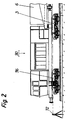
- Fig. 1
- eine Seitenansicht der erfindungsgemäßen Maschine mit teilweise weggebrochenem Antriebswagen;
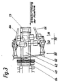
- Fig. 2
- eine Seitenansicht des Antriebswagens mit einem vorderen Abschnitt der Brücke;
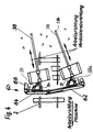
- Fig. 3
- eine Aufsicht auf den Arbeitsbereich der Maschine gemäß Fig. 1;
- Fig. 4
- eine Aufsicht auf den Arbeitsbereich der Maschine mit eigenangetriebenen Bodenverdichtern;
- Fig. 5
- einen Verfahrensablauf zur Sanierung eines vorhandenen Oberbaus;
- Fig. 6
- einen Aushub des Altschotters einschließlich einer Teilschicht des Unterbaus;
- Fig. 7
- einen stufenweisen Aushub des Oberbaus einschließlich einer Teilschicht des Unterbaus;
- Fig. 8
- eine Variante der Verdichtung einer aus Sand bestehenden Planumsschutzschicht; und
- Fig. 9
- eine Variante der Verdichtung einer aus Sand bestehenden Planumsschutzschicht.
- Fig. 1
- a side view of the machine according to the invention with the drive car partially broken away;
- Fig. 2
- a side view of the drive car with a front portion of the bridge;
- Fig. 3
- a plan of the working area of the machine according to FIG. 1;
- Fig. 4
- a supervision of the working area of the machine with self-propelled soil compactors;
- Fig. 5
- a procedure for the renovation of an existing superstructure;
- Fig. 6
- excavation of the old ballast including a sub-layer of the substructure;
- Fig. 7
- gradual excavation of the superstructure including a sub-layer of the substructure;
- Fig. 8
- a variant of the compaction of a formation protection layer consisting of sand; and
- Fig. 9
- a variant of the compaction of a formation protection layer consisting of sand.
Die Fig. 1 bis 4 zeigen eine Maschine zum Einbau von Sand 5 oder Schotter zwischen einem Planum 1 und einem Gleis 2. Auf dem Gleis 2 läuft ein vorderes Drehgestell 3 und ein hinteres Drehgestell 4. Auf den beiden Drehgestellen 3 und 4 ist eine gelenkfreie, in sich steife, d.h. selbsttragende Brücke 6 gelagert.1 to 4 show a machine for the installation of
Im Arbeitsfeld zwischen den mit der Brücke 6 verbundenen Gleishebeeinrichtungen 20 und 22 sind ein schwenkbares Förderband 42, eine quer zur Arbeitsrichtung liegende Schüttrinne 40, die sich über dem Materialeinbaubereich befindet, und eine Verdichtereinrichtung 30 angeordnet, um Sand 5 oder Schotter aus einer hinter dem hinteren Drehgestell 4 angekoppelten Transporteinrichtung, d.h. von deren Förderband 100 aufzunehmen, mittels einem ersten Förderband 14 bis etwa in die Mitte der Brücke 6 zu fördern, über einen stationären Trichter 13 auf das schwenkbare zweite Förderband 42 zu übergeben und mittels diesem zu verteilen, anschließend zu planieren und/oder zu verdichten.In the working area between the
Wie insbesondere der Fig. 1 entnehmbar ist, ist die Brücke 6 über ihre gesamte Länge selbsttragend ausgebildet und besitzt in Arbeitsrichtung vor dem hinteren Drehgestell 4 eine hintere Hebeeinrichtung 20 für das Gleis 2, die über hydraulische Hebearme an der Brücke 6 befestigt ist und in bekannter Weise mit Heberollen 21 unter die Schienenköpfe greift. In Arbeitsrichtung vor der Hebeeinrichtung 20 für das Gleis 2 befindet sich eine Verdichtereinrichtung 30, die aus zwei quer zur Arbeitsrichtung verlaufenden Reihen 32 und 34 von beabstandeten Bodenverdichtern 36 besteht, wobei die Bodenverdichter 36 der zweiten Reihe 34 gegenüber den Bodenverdichtern 36 der ersten Reihe 32 einen Querversatz aufweisen und dadurch auf Lücke gesetzt sind. Die Relativbewegung der Bodenverdichter gegenüber der Maschine ist dabei gleich Null.1, the
Figur 4 zeigt ein weiteres Ausführungsbeispiel der Verdichtereinrichtung 30, die in der dargestellten Ausführungsform aus zwei im wesentlichen in Längsrichtung der Maschine angeordneten Führungen 38 und zwei daran beweglich angeordneten Bodenverdichtern 36 besteht. Die Führungen 38 sind mit ihrem einen Ende 38a an der Planiereinrichtung 60 angelenkt, das andere Ende 38b ist frei beweglich. Die Bodenverdichter 36 sind längs der Führungen 38 verschiebbar geführt und bewegen sich bei Betrieb längs dieser Führungen, wenn bewegte Teile, z.B. eine mit Vibration beaufschlagte Bodenplatte den darunterliegenden Sand oder Schotter verdichten. An dem angelenkten Ende 38a der Führungen 38 sind Stellzylinder/kolben-Anordnungen 39 vorgesehen, welche ein Verschwenken der Führungen 38 um ihren Anlenkpunkt 38a zulassen. In einer besonders bevorzugten Ausführungsform wird die Vibration der Bodenplatte durch einen im Bodenverdichter umlaufenden Exzenter erzeugt, der gleichzeitig die Längsverschiebung des Bodenverdichter längs der Führung 38 bewirkt. Dadurch wird erreicht, daß die Bodenverdichter 36 beim Verdichten mit einer Relativbewegung zur gesamten Maschine arbeiten, beim Verdichten von Sand wird verhindert, daß die Bodenverdichter 36 zu lange auf derselben Stelle arbeiten und den darunterliegenden verdichteten Sand wieder locker schlagen.FIG. 4 shows a further exemplary embodiment of the
Ein weiterer Vorteil der Ausführungsform gemäß Fig. 4 besteht darin, daß die Führungen 38 leicht gegen die Längsrichtung oder Arbeitsrichtung der Maschine - in Abhängigkeit von der Breite des zu verdichtenden Gleisbettes - schräg nach außen gestellt werden können, so daß die Arbeitsbreite der Verdichtereinrichtung 30 der Breite des Gleisbettes angepaßt werden kann. Außerdem wird vermieden, daß Querrinnen entstehen, da die Bodenverdichter 36 im wesentlichen in Längsrichtung der Maschine überlappend arbeiten.Another advantage of the embodiment according to FIG. 4 is that the
Speziell für die Schotterverdichtung kann statt Flächenverdichtern 36 eine bekannte Rüttelbohle eingesetzt werden.A known vibrating screed can be used instead of
In Arbeitsrichtung vor der Verdichtereinrichtung 30 ist eine Planiereinrichtung 60 als Planierpflug ausgebildet, welcher über die gesamte Arbeitsbreite der Maschine verläuft, dessen Pflugspitze als Gelenk ausgebildet ist und der aus mindestens zwei teleskopierbaren horizontalen Abschnitten 62 und 64 besteht, die an ihren Enden an Armen 66 befestigt sind, die ihrerseits an der Brücke 6 beweglich angelenkt sind. An den Armen 66 sitzt auch die Verdichtereinrichtung 30.In the working direction in front of the
Der Planierpflug ist höhenverstellbar angeordnet. Über dem Planierpflug befindet sich ein Empfänger 70, der auf Signale einer Peileinrichtung 72 anspricht, die in Arbeitsrichtung ausreichend weit vor der Maschine aufgestellt ist und die jeweilige Höhe der aufzubringenden Sand- oder Schotterschicht festlegt. Je nach den empfangenen Peilsignalen läßt sich der Planierpflug manuell oder automatisch auf eine entsprechende Höhe einstellen.The leveling plow is height adjustable. There is a receiver 70 above the leveling plow, which responds to signals from a
Über dem Planierpflug und der Verdichtereinrichtung 30 ist ein schwenkbares zweites Förderband 42 angeordnet, dessen Abwurfende - in Arbeitsrichtung - vor dem Planierpflug über einer quer zur Arbeitsrichtung der Maschine angeordneten Schüttrinne 40 endet. Mittels dem schwenkbaren Förderband 42 wird das abzugebende Bettungsmaterial, Sand 5 oder Schotter, gemäß der geforderten Breite der Planumsschutzschicht oder des Schotterbettes verteilt, anschließend vom Planierpflug planiert und dann von der Verdichtereinrichtung 30 verdichtet. Die Schüttrinne 40 leitet das Bettungsmaterial in die Schwellenfächer.A pivotable
In Arbeitsrichtung vor der Schüttrinne 40 befindet sich eine vordere Gleishebeeinrichtung 22, die ebenfalls über hydraulisch betätigbare Hebearme an der Brücke 6 angeordnet ist und mittels Heberollen 21 unter die Schienenköpfe greift.In the working direction in front of the
Unmittelbar vor dem hinteren Drehgestell 4 sind die Aufnahmen für Flächenverdichter 36 derart ausschwenkbar, daß mit einem am Ende dieser Aufnahmen angeordneten Flächenverdichter 36 die Böschung der aufgeschütteten und planierten Sandschicht oder Schotterschicht verdichtet werden kann.Immediately in front of the rear bogie 4, the receptacles for
Das vordere Drehgestell 3 der Maschine, auf dem sich das vordere Ende der Brücke 6 abstützt, ist gleichzeitig das hintere Drehgestell des Antriebswagens 90, der - in der dargestellten Ausführungsform, vergleiche insbesondere Fig. 2 - noch ein weiteres eigenes Drehgestell 96 besitzt und neben den Antriebsaggregaten auch noch die Steueraggregate für die Maschine beinhaltet.The
Die Bedienung der Maschine bei Arbeitsfahrt kann u.a. aus der an der Brücke 6 angeordneten Kabine 15 erfolgen.The operation of the machine during work travel can include from the
Die Arbeitseinrichtungen der Maschine sind in der jeweiligen Transportstellung unterhalb der Brücke 6 verriegelbar.The working devices of the machine can be locked in the respective transport position below the
Die kompakte Anordnung der Arbeitseinrichtungen unter der Brücke 6, insbesondere die kompakte Anordnung der Schüttrinne 40, des Planierpfluges und der Verdichtereinrichtung 30, ermöglicht den qualitativ hochwertigen Einbau einer Planumsschutzschicht aus Sand 5 und - in einen zweiten Arbeitsgang - eine Ablage eines entsprechenden Schotterbettes auf dieser Planumsschutzschicht, wobei insbesondere auch wegen der vorteilhaft angeordneten Verdichtereinrichtung 30 eine hohe Arbeitsgeschwindigkeit der einzelnen Arbeitsgänge erzielbar ist.The compact arrangement of the work equipment under the
Anhand der Fig. 5 bis 9 wird ein Verfahren zum Umbau des Oberbaus eines Bahnkörpers beschrieben. Das Gleis 2 wird aufgenommen und der Altschotter 50 bis zum Altplanum 1a entfernt. Der Altschotter 50 wird in Arbeitsrichtung abtransportiert. Das Gleis 2 wird auf dem Altplanum 1a abgelegt. Danach wird das Gleis 2 angehoben und eine Planumsschutzschicht, vorzugsweise Sand 5, eingebracht. Das Gleis 2 wird auf der Planumsschutzschicht abgelegt. Im nächsten Verfahrensschritt wird das Gleis 2 wiederum aufgenommen und der schotter eingebracht sowie das Gleis 2 auf dem bzv. im Schotter abgelegt.A method for converting the superstructure of a web body is described with reference to FIGS. 5 to 9. The
Mit dem Verfahren kann jede geforderte Schichtdicke des Oberbaus eines zu sanierenden Bahnkörpers aufgenommen werden.With the method, any required layer thickness of the superstructure of a web body to be renovated can be absorbed.
Dabei ist es möglich, den Oberbau in einem Verfahrensschritt aufzunehmen und abzutransportieren oder den Oberbau in mehreren Teilschichten, gegebenenfalls einschließlich von Teilschichten des Unterbaus, aufzunehmen und abzutransportieren. Nach dem Einbringen des Sandes 5 wird dieser in der Regel planiert und/oder verdichtet. Das Verfahren läßt es zu, daß vor dem Einbringen einer Teilschicht des Sandes 5 die tiefergelegene Teilschicht planiert und/oder verdichtet wird, wobei die Oberfläche der Teilschicht zuvor gegebenenfalls aufgelockert wurde. Das Einbringen von Teilschichten garantiert die Verdichtung des Sandes 5 bis in die Sohle der Planumsschutzschicht. Gegebenenfalls ist der Sand 5 vor dem Einbringen oder vor dem Verdichten nachzufeuchten.It is possible to pick up and remove the superstructure in one process step or to pick up and remove the superstructure in several sub-layers, possibly including sub-layers of the substructure. After the
Die Verfahrensweisen nach Fig. 8 und 9 können auch parallel zueinander durchgeführt werden. Durch das Einbringen von Teilschichten werden die Biegespannungen in den Schienen des Gleises 2, die durch das Anheben des Gleises 2 auftreten, auf ein Minimum begrenzt bzw. es kann jede geforderte oder notwendige Dicke einer Planumsschutzschicht realisiert werden. Das Verfahren läßt es ebenfalls zu, Vlies, Folien oder andere Materialien als Planumsschutzschicht zu verwenden.8 and 9 can also be carried out in parallel. By introducing partial layers, the bending stresses in the rails of the
Claims (28)
- A machine for applying sand or ballast between a substructure and a track, having a working area which is delimited, as seen in the working direction, by a front bogie and a rear bogie, having a bridge connecting the bogies, and lifting devices arranged in the working area for lifting the track, and devices for processing sand or ballast in the working area on formations having no ballast, when the track is lifted, characterized in that the bridge (6) is constructed to be self-supporting over its entire length, in that a first transporting device (14) is arranged from one end up to approximately the centre of the bridge (6) and at least one second horizontally and/or vertically pivotal transporting device (42) connected thereto is arranged below the bridge (6), and in that a respective lifting device (20, 22) for the track (2) is arranged behind the front bogie (3) and in front of the rear bogie (4).
- A machine for applying sand or ballast between a substructure and a track according to Claim 1, characterized in that a transfer station (13) is arranged between the transporting devices (14, 42).
- A machine according to Claim 1 or 2, characterized in that at least one levelling device (60) is provided which may be placed below the lifted track (2) for levelling the sand (5) or ballast which has already been delivered by the transporting devices (14, 42).
- A machine according to one of the preceding claims, characterized in that at least one compressor device (30) is provided which works the sand or ballast laid down below the lifted track (2) after the levelling device (60).
- A machine according to one of the preceding claims, characterized in that, as seen in opposition to the working direction, there is arranged firstly the delivery end of the second transporting device (42), then a levelling device (60) and then a compressor device (30).
- A machine for applying sand or ballast between a substructure and a track according to one of Claims 3 to 5, characterized in that the levelling device(s) (60) may be adjusted by means of adjustable arms (66) secured to the bridge (6).
- A machine for applying sand or ballast between a substructure and a track according to one of Claims 3 to 6, characterized in that the levelling device (60) is a vertically adjustable levelling plough-type means.
- A machine for applying sand or ballast between a substructure and a track according to Claim 7, characterized in that the tip of the levelling plough-type means is constructed as an articulating means.
- A machine for applying sand or ballast between a substructure and a track according to Claim 7 or 8, characterized in that the plough blades of the levelling plough-type means have telescopic sections (62, 64).
- A machine for applying sand or ballast between a substructure and a track according to one of Claims 1 to 9, characterized in that, at the delivery end of the second transporting device (42), there is arranged a delivery chute (40) transverse to the working direction and above the track (2).
- A machine for applying sand or ballast between a substructure and a track according to one of Claims 3 to 10, characterized in that above one levelling device (60) there is arranged a receiver (70) which is connected to the levelling device (60) and which responds to signals from a direction finding means (72), and in that the adjusting level of the levelling device(s) (60) is self-adjusting.
- A machine for applying sand or ballast between a substructure and a track according to one of Claims 3 to 11, characterized in that, in accordance with the working direction of the machine, a loosening device for the track-formation protection layer or the used track formation (la) is arranged in front of the levelling device (60).
- A machine for applying sand or ballast between a substructure and a track according to one of Claims 1 to 12, characterized in that two second transporting devices (42) are arranged next to one another and execute a pivotal movement in the same or in opposing directions.
- A machine for applying sand or ballast between a substructure and a track according to one of Claims 1 to 13, characterized in that at least one delivery chute (40) is arranged transverse to the working direction of the machine and above the track (2) at the delivery end of the second transporting devices (42).
- A machine for applying sand or ballast between a substructure and a track according to one of Claims 4 to 14, characterized in that the compressor device (30) contains a plurality of spaced ground compressors (36) in rows (32, 34) running transverse to the working direction, these ground compressors (36) being arranged to have a fixedly staggered gap from one row (32) to the next (34) and approximately compressing the working width in accordance with the levelling device (60).
- A machine for applying sand or ballast between a substructure and a track according to Claim 15, characterized in that the compressor device (30) is securely articulated to the machine, and in that, in relation to the machine, the relative movement of the ground compressors (36) in the working direction is equal to zero.
- A machine for applying sand or ballast between a substructure and a track, in particular according to one of Claims 1 to 14, characterized in that the compressor device (30) contains at least one guide (38) which is parallel or oblique or curved in relation to the working direction of the machine and contains at least one automatically driven ground compressor (36).
- A machine for applying sand or ballast between a substructure and a track according to Claim 17, characterized in that the guide (38) is securely articulated to a device (30, 60) or the machine itself, and the ground compressor (36) is movably connected to the guide (38).
- A machine for applying sand or ballast between a substructure and a track according to Claim 17, characterized in that the guide (38) is movably arranged on a device (30, 60) or the machine itself, and the ground compressor (36) is securely articulated to the guide (38).
- A machine for applying sand or ballast between a substructure and a track according to one of Claims 4 to 14, characterized in that the compressor device (30) or the ground compressor(s) (36) is/are arranged to be detached from the machine.
- A machine for applying sand or ballast between a substructure and a track according to one of Claims 4 to 20, characterized in that the compressor device (30) may be locked in a separate transporting position below the bridge (6).
- A machine for applying sand or ballast between a substructure and a track according to one of Claims 1 to 21, characterized in that in each case at least one ground compressor (36) is laterally displaceable at a spacing from the machine for compressing an embankment.
- A machine for applying sand or ballast between a substructure and a track according to one of Claims 1 to 22, characterized in that a driving carriage (90) is arranged in front of the front bogie.
- A machine for applying sand or ballast between a substructure and a track according to one of Claims 1 to 21, characterized in that the bridge (6) is mounted on a driving carriage (90).
- A process for rebuilding the superstructure of a formation by means of a machine according to one of Claims 1 to 24, characterized in that firstly the track is lifted and the used ballast (50) located thereunder is removed down to the used track formation (la) of the substructure and, if necessary, additionally a partial layer of the substructure is removed, and the track (2) is then laid down on the track formation, in that the track (2) is then picked up again by means of a machine according to one of Claims 1 to 24 and a track-formation protection layer of sand (5) is placed on, in that the track (2) is then laid down on the track-formation protection layer, the track (2) is again picked up by means of a machine according to one of Claims 1 to 24 and the ballast is placed on the protection layer, and in that the track is finally laid down on or in the ballast.
- A process according to Claim 25, characterized in that, before the placing-on of the track-formation protection layer, the used track formation (la) of the substructure is loosened, levelled and/or compressed.
- A process according to one of Claims 25 or 26, characterized in that the placed-on track-formation protection layer, or a partial layer of the track-formation protection layer, is levelled and/or compressed immediately after it has been placed on.
- A process according to one of Claims 25 to 27, characterized in that the placed-on track-formation protection layer, or a partial layer of the track-formation protection, layer, is levelled and/or compressed before a further partial layer or the ballast has been placed on.
Applications Claiming Priority (4)
| Application Number | Priority Date | Filing Date | Title |
|---|---|---|---|
| DE9200256U | 1992-01-11 | ||
| DE9200256U DE9200256U1 (en) | 1992-01-11 | 1992-01-11 | |
| DE4236487 | 1992-10-29 | ||
| DE4236487A DE4236487C2 (en) | 1992-01-11 | 1992-10-29 | Process for renewing the superstructure of a web body and machine for use in this process |
Publications (2)
| Publication Number | Publication Date |
|---|---|
| EP0551835A1 EP0551835A1 (en) | 1993-07-21 |
| EP0551835B1 true EP0551835B1 (en) | 1996-08-14 |
Family
ID=25919934
Family Applications (1)
| Application Number | Title | Priority Date | Filing Date |
|---|---|---|---|
| EP93100197A Expired - Lifetime EP0551835B1 (en) | 1992-01-11 | 1993-01-08 | Machine for placing sand or ballast between rails and railway understructure, and method for replacing the railway superstructure |
Country Status (3)
| Country | Link |
|---|---|
| EP (1) | EP0551835B1 (en) |
| AT (1) | ATE141360T1 (en) |
| DE (1) | DE4244958C2 (en) |
Families Citing this family (4)
| Publication number | Priority date | Publication date | Assignee | Title |
|---|---|---|---|---|
| DE102007037441B3 (en) * | 2007-08-08 | 2009-01-22 | Deutsche Gleis- Und Tiefbau Gmbh | Track-transportable bulk freight wagon |
| DE102009041237B4 (en) | 2009-09-11 | 2019-07-11 | Ralf Zürcher | Method for rehabilitating the track substructure of a railway line |
| CN105383504B (en) * | 2015-12-11 | 2017-09-12 | 中车山东机车车辆有限公司 | A kind of flat tiny fragments of stone, coal, etc. system of stone tiny fragments of stone, coal, etc. hopper wagon |
| AT518324B1 (en) * | 2016-02-16 | 2018-04-15 | Plasser & Theurer Export Von Bahnbaumaschinen Gmbh | Track construction machine and method for compacting a ballast bed |
Family Cites Families (7)
| Publication number | Priority date | Publication date | Assignee | Title |
|---|---|---|---|---|
| DE1534109C2 (en) * | 1965-12-10 | 1975-01-16 | Rheiner Maschinenfabrik Windhoff Ag, 4440 Rheine | Plow-like device for distributing and profiling the bedding bulkhead of a track |
| US3610157A (en) * | 1969-06-11 | 1971-10-05 | Mikhail Antonovich Plokhotsky | Machine for constructing and repairing railway tracks |
| AT317965B (en) * | 1969-12-18 | 1974-09-25 | Plasser Bahnbaumasch Franz | Machine for picking up, cleaning and reintroducing ballast ballast from railroad tracks |
| US4136618A (en) * | 1977-06-06 | 1979-01-30 | Boyer Jean Jacques | Railroad lifting device for ballast cleaning and levelling machines |
| AT359113B (en) * | 1978-06-16 | 1980-10-27 | Plasser Bahnbaumasch Franz | SELF-DRIVE TRACK BED CLEANING MACHINE |
| AT379176B (en) * | 1981-12-22 | 1985-11-25 | Plasser Bahnbaumasch Franz | DRIVABLE PLANT AND METHOD FOR CONTINUOUSLY PROGRESSIVE RENOVATION OF THE RAILWAYS |
| ATA126486A (en) * | 1986-05-13 | 1987-05-15 | Wageneder Sbm Gmbh | CONVERTIBLE CONVERTIBLE TROLLEY FOR RAILWAYS ON RAILS |
-
1992
- 1992-10-29 DE DE4244958A patent/DE4244958C2/en not_active Expired - Fee Related
-
1993
- 1993-01-08 AT AT93100197T patent/ATE141360T1/en not_active IP Right Cessation
- 1993-01-08 EP EP93100197A patent/EP0551835B1/en not_active Expired - Lifetime
Also Published As
| Publication number | Publication date |
|---|---|
| EP0551835A1 (en) | 1993-07-21 |
| DE4244958C2 (en) | 2001-02-01 |
| ATE141360T1 (en) | 1996-08-15 |
Similar Documents
| Publication | Publication Date | Title |
|---|---|---|
| EP0255564B1 (en) | Machine for replacing or renewing the rails and sleepers of an existing track | |
| DE3035910C2 (en) | ||
| DE3227725A1 (en) | DRIVABLE PLANT AND METHOD FOR CONTINUOUSLY PROGRESSIVE RENOVATION OF THE RAILWAYS | |
| DD154623A5 (en) | RETRACTABLE BUCKET CLEANING MACHINE AND METHOD FOR TREATING THE BED SCATTER | |
| DE3634399C2 (en) | Mobile track tamping, leveling and straightening machine | |
| EP1172481B1 (en) | Railway track renewal machine | |
| DE3634397C2 (en) | Mobile system for cleaning and subsequently compacting the ballast bedding of tracks | |
| DE4237712C2 (en) | Plant for the production of a formation protection layer | |
| DE3819717A1 (en) | CONTINUOUSLY (NON-STOP) TRAVELABLE TRACKING MACHINE | |
| EP0771909B1 (en) | Machine for dismantling old and installing new railway tracks | |
| EP0609647B1 (en) | Renewal or cleaning apparatus for ballastway | |
| EP1179634B1 (en) | Railway track renewal machine | |
| DE3106063A1 (en) | TRACK CONSTRUCTION MACHINE WITH A GRAVEL BED ROOM AND PLANNER DEVICE | |
| DE3634398C2 (en) | Mobile system for the continuous renewal of the rails and sleepers of a track | |
| EP0551835B1 (en) | Machine for placing sand or ballast between rails and railway understructure, and method for replacing the railway superstructure | |
| EP0056497A1 (en) | Frame wagon in a train for the subsoil stabilization of railway tracks | |
| DE202008003589U1 (en) | Track rehabilitation machine with base layer milling machine | |
| EP1195468A2 (en) | Machine for renewing a railway track | |
| DE2557372C2 (en) | Mobile track-laying machine, for picking up, distributing and reintroducing separate bedding materials, especially point cleaning machine | |
| EP0239712B1 (en) | Mobile track-treating machine for removing, cleaning and reintroducing ballast with a ballast compacting device | |
| DE2714050C2 (en) | ||
| CH474618A (en) | Process for cleaning, leveling and compacting the ballast of track beds and at the same time stabilizing the subgrade with the track lying flat, as well as a machine for carrying out the process | |
| DE4236487C2 (en) | Process for renewing the superstructure of a web body and machine for use in this process | |
| AT404947B (en) | TROLLEYS FOR THE GRADUATION OF A TRACK | |
| AT400862B (en) | TRACK CONSTRUCTION MACHINE WITH HEIGHT-ADJUSTABLE TRACK LIFTING UNIT |
Legal Events
| Date | Code | Title | Description |
|---|---|---|---|
| PUAI | Public reference made under article 153(3) epc to a published international application that has entered the european phase |
Free format text: ORIGINAL CODE: 0009012 |
|
| AK | Designated contracting states |
Kind code of ref document: A1 Designated state(s): AT BE CH DE FR IT LI NL |
|
| 17P | Request for examination filed |
Effective date: 19931112 |
|
| 17Q | First examination report despatched |
Effective date: 19950131 |
|
| GRAH | Despatch of communication of intention to grant a patent |
Free format text: ORIGINAL CODE: EPIDOS IGRA |
|
| GRAH | Despatch of communication of intention to grant a patent |
Free format text: ORIGINAL CODE: EPIDOS IGRA |
|
| GRAA | (expected) grant |
Free format text: ORIGINAL CODE: 0009210 |
|
| AK | Designated contracting states |
Kind code of ref document: B1 Designated state(s): AT BE CH DE FR IT LI NL |
|
| REF | Corresponds to: |
Ref document number: 141360 Country of ref document: AT Date of ref document: 19960815 Kind code of ref document: T |
|
| REF | Corresponds to: |
Ref document number: 59303386 Country of ref document: DE Date of ref document: 19960919 |
|
| ITF | It: translation for a ep patent filed |
Owner name: MODIANO & ASSOCIATI S.R.L. |
|
| ET | Fr: translation filed | ||
| PG25 | Lapsed in a contracting state [announced via postgrant information from national office to epo] |
Ref country code: LI Effective date: 19970131 Ref country code: CH Effective date: 19970131 |
|
| PLBE | No opposition filed within time limit |
Free format text: ORIGINAL CODE: 0009261 |
|
| STAA | Information on the status of an ep patent application or granted ep patent |
Free format text: STATUS: NO OPPOSITION FILED WITHIN TIME LIMIT |
|
| PG25 | Lapsed in a contracting state [announced via postgrant information from national office to epo] |
Ref country code: BE Effective date: 19970731 |
|
| 26N | No opposition filed | ||
| REG | Reference to a national code |
Ref country code: CH Ref legal event code: PL |
|
| NLS | Nl: assignments of ep-patents |
Owner name: FRANZ PLASSER BAHNBAUMASCHINEN- INDUSTRIEGESELLSCH |
|
| REG | Reference to a national code |
Ref country code: FR Ref legal event code: CD |
|
| PGFP | Annual fee paid to national office [announced via postgrant information from national office to epo] |
Ref country code: IT Payment date: 20100123 Year of fee payment: 18 Ref country code: FR Payment date: 20100211 Year of fee payment: 18 |
|
| PGFP | Annual fee paid to national office [announced via postgrant information from national office to epo] |
Ref country code: DE Payment date: 20100318 Year of fee payment: 18 Ref country code: AT Payment date: 20091215 Year of fee payment: 18 |
|
| PGFP | Annual fee paid to national office [announced via postgrant information from national office to epo] |
Ref country code: NL Payment date: 20100127 Year of fee payment: 18 |
|
| REG | Reference to a national code |
Ref country code: NL Ref legal event code: V1 Effective date: 20110801 |
|
| REG | Reference to a national code |
Ref country code: FR Ref legal event code: ST Effective date: 20110930 |
|
| PG25 | Lapsed in a contracting state [announced via postgrant information from national office to epo] |
Ref country code: FR Free format text: LAPSE BECAUSE OF NON-PAYMENT OF DUE FEES Effective date: 20110131 |
|
| PG25 | Lapsed in a contracting state [announced via postgrant information from national office to epo] |
Ref country code: AT Free format text: LAPSE BECAUSE OF NON-PAYMENT OF DUE FEES Effective date: 20110108 |
|
| REG | Reference to a national code |
Ref country code: DE Ref legal event code: R119 Ref document number: 59303386 Country of ref document: DE Effective date: 20110802 |
|
| PG25 | Lapsed in a contracting state [announced via postgrant information from national office to epo] |
Ref country code: NL Free format text: LAPSE BECAUSE OF NON-PAYMENT OF DUE FEES Effective date: 20110801 Ref country code: IT Free format text: LAPSE BECAUSE OF NON-PAYMENT OF DUE FEES Effective date: 20110108 |
|
| PG25 | Lapsed in a contracting state [announced via postgrant information from national office to epo] |
Ref country code: DE Free format text: LAPSE BECAUSE OF NON-PAYMENT OF DUE FEES Effective date: 20110802 |