EP0540280A1 - Einrichtung zur Minderung von Stickoxiden in Rauchgasen aus Brennkraftmaschinen - Google Patents
Einrichtung zur Minderung von Stickoxiden in Rauchgasen aus Brennkraftmaschinen Download PDFInfo
- Publication number
- EP0540280A1 EP0540280A1 EP92309801A EP92309801A EP0540280A1 EP 0540280 A1 EP0540280 A1 EP 0540280A1 EP 92309801 A EP92309801 A EP 92309801A EP 92309801 A EP92309801 A EP 92309801A EP 0540280 A1 EP0540280 A1 EP 0540280A1
- Authority
- EP
- European Patent Office
- Prior art keywords
- nox
- release material
- absorption
- nox absorption
- exhaust conduit
- Prior art date
- Legal status (The legal status is an assumption and is not a legal conclusion. Google has not performed a legal analysis and makes no representation as to the accuracy of the status listed.)
- Granted
Links
Images


Classifications
-
- F—MECHANICAL ENGINEERING; LIGHTING; HEATING; WEAPONS; BLASTING
- F01—MACHINES OR ENGINES IN GENERAL; ENGINE PLANTS IN GENERAL; STEAM ENGINES
- F01N—GAS-FLOW SILENCERS OR EXHAUST APPARATUS FOR MACHINES OR ENGINES IN GENERAL; GAS-FLOW SILENCERS OR EXHAUST APPARATUS FOR INTERNAL COMBUSTION ENGINES
- F01N3/00—Exhaust or silencing apparatus having means for purifying, rendering innocuous, or otherwise treating exhaust
- F01N3/08—Exhaust or silencing apparatus having means for purifying, rendering innocuous, or otherwise treating exhaust for rendering innocuous
- F01N3/10—Exhaust or silencing apparatus having means for purifying, rendering innocuous, or otherwise treating exhaust for rendering innocuous by thermal or catalytic conversion of noxious components of exhaust
- F01N3/24—Exhaust or silencing apparatus having means for purifying, rendering innocuous, or otherwise treating exhaust for rendering innocuous by thermal or catalytic conversion of noxious components of exhaust characterised by constructional aspects of converting apparatus
- F01N3/30—Arrangements for supply of additional air
- F01N3/32—Arrangements for supply of additional air using air pump
-
- B—PERFORMING OPERATIONS; TRANSPORTING
- B01—PHYSICAL OR CHEMICAL PROCESSES OR APPARATUS IN GENERAL
- B01D—SEPARATION
- B01D53/00—Separation of gases or vapours; Recovering vapours of volatile solvents from gases; Chemical or biological purification of waste gases, e.g. engine exhaust gases, smoke, fumes, flue gases, aerosols
- B01D53/02—Separation of gases or vapours; Recovering vapours of volatile solvents from gases; Chemical or biological purification of waste gases, e.g. engine exhaust gases, smoke, fumes, flue gases, aerosols by adsorption, e.g. preparative gas chromatography
- B01D53/04—Separation of gases or vapours; Recovering vapours of volatile solvents from gases; Chemical or biological purification of waste gases, e.g. engine exhaust gases, smoke, fumes, flue gases, aerosols by adsorption, e.g. preparative gas chromatography with stationary adsorbents
- B01D53/0454—Controlling adsorption
-
- B—PERFORMING OPERATIONS; TRANSPORTING
- B01—PHYSICAL OR CHEMICAL PROCESSES OR APPARATUS IN GENERAL
- B01D—SEPARATION
- B01D53/00—Separation of gases or vapours; Recovering vapours of volatile solvents from gases; Chemical or biological purification of waste gases, e.g. engine exhaust gases, smoke, fumes, flue gases, aerosols
- B01D53/34—Chemical or biological purification of waste gases
- B01D53/74—General processes for purification of waste gases; Apparatus or devices specially adapted therefor
- B01D53/86—Catalytic processes
- B01D53/8696—Controlling the catalytic process
-
- B—PERFORMING OPERATIONS; TRANSPORTING
- B01—PHYSICAL OR CHEMICAL PROCESSES OR APPARATUS IN GENERAL
- B01D—SEPARATION
- B01D53/00—Separation of gases or vapours; Recovering vapours of volatile solvents from gases; Chemical or biological purification of waste gases, e.g. engine exhaust gases, smoke, fumes, flue gases, aerosols
- B01D53/34—Chemical or biological purification of waste gases
- B01D53/92—Chemical or biological purification of waste gases of engine exhaust gases
- B01D53/94—Chemical or biological purification of waste gases of engine exhaust gases by catalytic processes
- B01D53/9481—Catalyst preceded by an adsorption device without catalytic function for temporary storage of contaminants, e.g. during cold start
-
- B—PERFORMING OPERATIONS; TRANSPORTING
- B01—PHYSICAL OR CHEMICAL PROCESSES OR APPARATUS IN GENERAL
- B01D—SEPARATION
- B01D53/00—Separation of gases or vapours; Recovering vapours of volatile solvents from gases; Chemical or biological purification of waste gases, e.g. engine exhaust gases, smoke, fumes, flue gases, aerosols
- B01D53/34—Chemical or biological purification of waste gases
- B01D53/92—Chemical or biological purification of waste gases of engine exhaust gases
- B01D53/94—Chemical or biological purification of waste gases of engine exhaust gases by catalytic processes
- B01D53/9495—Controlling the catalytic process
-
- F—MECHANICAL ENGINEERING; LIGHTING; HEATING; WEAPONS; BLASTING
- F01—MACHINES OR ENGINES IN GENERAL; ENGINE PLANTS IN GENERAL; STEAM ENGINES
- F01N—GAS-FLOW SILENCERS OR EXHAUST APPARATUS FOR MACHINES OR ENGINES IN GENERAL; GAS-FLOW SILENCERS OR EXHAUST APPARATUS FOR INTERNAL COMBUSTION ENGINES
- F01N13/00—Exhaust or silencing apparatus characterised by constructional features ; Exhaust or silencing apparatus, or parts thereof, having pertinent characteristics not provided for in, or of interest apart from, groups F01N1/00 - F01N5/00, F01N9/00, F01N11/00
- F01N13/009—Exhaust or silencing apparatus characterised by constructional features ; Exhaust or silencing apparatus, or parts thereof, having pertinent characteristics not provided for in, or of interest apart from, groups F01N1/00 - F01N5/00, F01N9/00, F01N11/00 having two or more separate purifying devices arranged in series
- F01N13/0097—Exhaust or silencing apparatus characterised by constructional features ; Exhaust or silencing apparatus, or parts thereof, having pertinent characteristics not provided for in, or of interest apart from, groups F01N1/00 - F01N5/00, F01N9/00, F01N11/00 having two or more separate purifying devices arranged in series the purifying devices are arranged in a single housing
-
- F—MECHANICAL ENGINEERING; LIGHTING; HEATING; WEAPONS; BLASTING
- F01—MACHINES OR ENGINES IN GENERAL; ENGINE PLANTS IN GENERAL; STEAM ENGINES
- F01N—GAS-FLOW SILENCERS OR EXHAUST APPARATUS FOR MACHINES OR ENGINES IN GENERAL; GAS-FLOW SILENCERS OR EXHAUST APPARATUS FOR INTERNAL COMBUSTION ENGINES
- F01N13/00—Exhaust or silencing apparatus characterised by constructional features ; Exhaust or silencing apparatus, or parts thereof, having pertinent characteristics not provided for in, or of interest apart from, groups F01N1/00 - F01N5/00, F01N9/00, F01N11/00
- F01N13/011—Exhaust or silencing apparatus characterised by constructional features ; Exhaust or silencing apparatus, or parts thereof, having pertinent characteristics not provided for in, or of interest apart from, groups F01N1/00 - F01N5/00, F01N9/00, F01N11/00 having two or more purifying devices arranged in parallel
-
- F—MECHANICAL ENGINEERING; LIGHTING; HEATING; WEAPONS; BLASTING
- F01—MACHINES OR ENGINES IN GENERAL; ENGINE PLANTS IN GENERAL; STEAM ENGINES
- F01N—GAS-FLOW SILENCERS OR EXHAUST APPARATUS FOR MACHINES OR ENGINES IN GENERAL; GAS-FLOW SILENCERS OR EXHAUST APPARATUS FOR INTERNAL COMBUSTION ENGINES
- F01N3/00—Exhaust or silencing apparatus having means for purifying, rendering innocuous, or otherwise treating exhaust
- F01N3/02—Exhaust or silencing apparatus having means for purifying, rendering innocuous, or otherwise treating exhaust for cooling, or for removing solid constituents of, exhaust
- F01N3/021—Exhaust or silencing apparatus having means for purifying, rendering innocuous, or otherwise treating exhaust for cooling, or for removing solid constituents of, exhaust by means of filters
- F01N3/023—Exhaust or silencing apparatus having means for purifying, rendering innocuous, or otherwise treating exhaust for cooling, or for removing solid constituents of, exhaust by means of filters using means for regenerating the filters, e.g. by burning trapped particles
- F01N3/027—Exhaust or silencing apparatus having means for purifying, rendering innocuous, or otherwise treating exhaust for cooling, or for removing solid constituents of, exhaust by means of filters using means for regenerating the filters, e.g. by burning trapped particles using electric or magnetic heating means
-
- F—MECHANICAL ENGINEERING; LIGHTING; HEATING; WEAPONS; BLASTING
- F01—MACHINES OR ENGINES IN GENERAL; ENGINE PLANTS IN GENERAL; STEAM ENGINES
- F01N—GAS-FLOW SILENCERS OR EXHAUST APPARATUS FOR MACHINES OR ENGINES IN GENERAL; GAS-FLOW SILENCERS OR EXHAUST APPARATUS FOR INTERNAL COMBUSTION ENGINES
- F01N3/00—Exhaust or silencing apparatus having means for purifying, rendering innocuous, or otherwise treating exhaust
- F01N3/02—Exhaust or silencing apparatus having means for purifying, rendering innocuous, or otherwise treating exhaust for cooling, or for removing solid constituents of, exhaust
- F01N3/021—Exhaust or silencing apparatus having means for purifying, rendering innocuous, or otherwise treating exhaust for cooling, or for removing solid constituents of, exhaust by means of filters
- F01N3/031—Exhaust or silencing apparatus having means for purifying, rendering innocuous, or otherwise treating exhaust for cooling, or for removing solid constituents of, exhaust by means of filters having means for by-passing filters, e.g. when clogged or during cold engine start
-
- F—MECHANICAL ENGINEERING; LIGHTING; HEATING; WEAPONS; BLASTING
- F01—MACHINES OR ENGINES IN GENERAL; ENGINE PLANTS IN GENERAL; STEAM ENGINES
- F01N—GAS-FLOW SILENCERS OR EXHAUST APPARATUS FOR MACHINES OR ENGINES IN GENERAL; GAS-FLOW SILENCERS OR EXHAUST APPARATUS FOR INTERNAL COMBUSTION ENGINES
- F01N3/00—Exhaust or silencing apparatus having means for purifying, rendering innocuous, or otherwise treating exhaust
- F01N3/02—Exhaust or silencing apparatus having means for purifying, rendering innocuous, or otherwise treating exhaust for cooling, or for removing solid constituents of, exhaust
- F01N3/021—Exhaust or silencing apparatus having means for purifying, rendering innocuous, or otherwise treating exhaust for cooling, or for removing solid constituents of, exhaust by means of filters
- F01N3/033—Exhaust or silencing apparatus having means for purifying, rendering innocuous, or otherwise treating exhaust for cooling, or for removing solid constituents of, exhaust by means of filters in combination with other devices
-
- F—MECHANICAL ENGINEERING; LIGHTING; HEATING; WEAPONS; BLASTING
- F01—MACHINES OR ENGINES IN GENERAL; ENGINE PLANTS IN GENERAL; STEAM ENGINES
- F01N—GAS-FLOW SILENCERS OR EXHAUST APPARATUS FOR MACHINES OR ENGINES IN GENERAL; GAS-FLOW SILENCERS OR EXHAUST APPARATUS FOR INTERNAL COMBUSTION ENGINES
- F01N3/00—Exhaust or silencing apparatus having means for purifying, rendering innocuous, or otherwise treating exhaust
- F01N3/08—Exhaust or silencing apparatus having means for purifying, rendering innocuous, or otherwise treating exhaust for rendering innocuous
- F01N3/0807—Exhaust or silencing apparatus having means for purifying, rendering innocuous, or otherwise treating exhaust for rendering innocuous by using absorbents or adsorbents
- F01N3/0821—Exhaust or silencing apparatus having means for purifying, rendering innocuous, or otherwise treating exhaust for rendering innocuous by using absorbents or adsorbents combined with particulate filters
-
- F—MECHANICAL ENGINEERING; LIGHTING; HEATING; WEAPONS; BLASTING
- F01—MACHINES OR ENGINES IN GENERAL; ENGINE PLANTS IN GENERAL; STEAM ENGINES
- F01N—GAS-FLOW SILENCERS OR EXHAUST APPARATUS FOR MACHINES OR ENGINES IN GENERAL; GAS-FLOW SILENCERS OR EXHAUST APPARATUS FOR INTERNAL COMBUSTION ENGINES
- F01N3/00—Exhaust or silencing apparatus having means for purifying, rendering innocuous, or otherwise treating exhaust
- F01N3/08—Exhaust or silencing apparatus having means for purifying, rendering innocuous, or otherwise treating exhaust for rendering innocuous
- F01N3/0807—Exhaust or silencing apparatus having means for purifying, rendering innocuous, or otherwise treating exhaust for rendering innocuous by using absorbents or adsorbents
- F01N3/0828—Exhaust or silencing apparatus having means for purifying, rendering innocuous, or otherwise treating exhaust for rendering innocuous by using absorbents or adsorbents characterised by the absorbed or adsorbed substances
- F01N3/0842—Nitrogen oxides
-
- F—MECHANICAL ENGINEERING; LIGHTING; HEATING; WEAPONS; BLASTING
- F01—MACHINES OR ENGINES IN GENERAL; ENGINE PLANTS IN GENERAL; STEAM ENGINES
- F01N—GAS-FLOW SILENCERS OR EXHAUST APPARATUS FOR MACHINES OR ENGINES IN GENERAL; GAS-FLOW SILENCERS OR EXHAUST APPARATUS FOR INTERNAL COMBUSTION ENGINES
- F01N3/00—Exhaust or silencing apparatus having means for purifying, rendering innocuous, or otherwise treating exhaust
- F01N3/08—Exhaust or silencing apparatus having means for purifying, rendering innocuous, or otherwise treating exhaust for rendering innocuous
- F01N3/0807—Exhaust or silencing apparatus having means for purifying, rendering innocuous, or otherwise treating exhaust for rendering innocuous by using absorbents or adsorbents
- F01N3/0871—Regulation of absorbents or adsorbents, e.g. purging
- F01N3/0878—Bypassing absorbents or adsorbents
-
- F—MECHANICAL ENGINEERING; LIGHTING; HEATING; WEAPONS; BLASTING
- F01—MACHINES OR ENGINES IN GENERAL; ENGINE PLANTS IN GENERAL; STEAM ENGINES
- F01N—GAS-FLOW SILENCERS OR EXHAUST APPARATUS FOR MACHINES OR ENGINES IN GENERAL; GAS-FLOW SILENCERS OR EXHAUST APPARATUS FOR INTERNAL COMBUSTION ENGINES
- F01N3/00—Exhaust or silencing apparatus having means for purifying, rendering innocuous, or otherwise treating exhaust
- F01N3/08—Exhaust or silencing apparatus having means for purifying, rendering innocuous, or otherwise treating exhaust for rendering innocuous
- F01N3/0807—Exhaust or silencing apparatus having means for purifying, rendering innocuous, or otherwise treating exhaust for rendering innocuous by using absorbents or adsorbents
- F01N3/0871—Regulation of absorbents or adsorbents, e.g. purging
- F01N3/0885—Regeneration of deteriorated absorbents or adsorbents, e.g. desulfurization of NOx traps
-
- F—MECHANICAL ENGINEERING; LIGHTING; HEATING; WEAPONS; BLASTING
- F01—MACHINES OR ENGINES IN GENERAL; ENGINE PLANTS IN GENERAL; STEAM ENGINES
- F01N—GAS-FLOW SILENCERS OR EXHAUST APPARATUS FOR MACHINES OR ENGINES IN GENERAL; GAS-FLOW SILENCERS OR EXHAUST APPARATUS FOR INTERNAL COMBUSTION ENGINES
- F01N3/00—Exhaust or silencing apparatus having means for purifying, rendering innocuous, or otherwise treating exhaust
- F01N3/08—Exhaust or silencing apparatus having means for purifying, rendering innocuous, or otherwise treating exhaust for rendering innocuous
- F01N3/10—Exhaust or silencing apparatus having means for purifying, rendering innocuous, or otherwise treating exhaust for rendering innocuous by thermal or catalytic conversion of noxious components of exhaust
- F01N3/18—Exhaust or silencing apparatus having means for purifying, rendering innocuous, or otherwise treating exhaust for rendering innocuous by thermal or catalytic conversion of noxious components of exhaust characterised by methods of operation; Control
- F01N3/20—Exhaust or silencing apparatus having means for purifying, rendering innocuous, or otherwise treating exhaust for rendering innocuous by thermal or catalytic conversion of noxious components of exhaust characterised by methods of operation; Control specially adapted for catalytic conversion ; Methods of operation or control of catalytic converters
- F01N3/2053—By-passing catalytic reactors, e.g. to prevent overheating
-
- F—MECHANICAL ENGINEERING; LIGHTING; HEATING; WEAPONS; BLASTING
- F01—MACHINES OR ENGINES IN GENERAL; ENGINE PLANTS IN GENERAL; STEAM ENGINES
- F01N—GAS-FLOW SILENCERS OR EXHAUST APPARATUS FOR MACHINES OR ENGINES IN GENERAL; GAS-FLOW SILENCERS OR EXHAUST APPARATUS FOR INTERNAL COMBUSTION ENGINES
- F01N3/00—Exhaust or silencing apparatus having means for purifying, rendering innocuous, or otherwise treating exhaust
- F01N3/08—Exhaust or silencing apparatus having means for purifying, rendering innocuous, or otherwise treating exhaust for rendering innocuous
- F01N3/10—Exhaust or silencing apparatus having means for purifying, rendering innocuous, or otherwise treating exhaust for rendering innocuous by thermal or catalytic conversion of noxious components of exhaust
- F01N3/24—Exhaust or silencing apparatus having means for purifying, rendering innocuous, or otherwise treating exhaust for rendering innocuous by thermal or catalytic conversion of noxious components of exhaust characterised by constructional aspects of converting apparatus
- F01N3/28—Construction of catalytic reactors
- F01N3/2882—Catalytic reactors combined or associated with other devices, e.g. exhaust silencers or other exhaust purification devices
-
- F—MECHANICAL ENGINEERING; LIGHTING; HEATING; WEAPONS; BLASTING
- F01—MACHINES OR ENGINES IN GENERAL; ENGINE PLANTS IN GENERAL; STEAM ENGINES
- F01N—GAS-FLOW SILENCERS OR EXHAUST APPARATUS FOR MACHINES OR ENGINES IN GENERAL; GAS-FLOW SILENCERS OR EXHAUST APPARATUS FOR INTERNAL COMBUSTION ENGINES
- F01N2240/00—Combination or association of two or more different exhaust treating devices, or of at least one such device with an auxiliary device, not covered by indexing codes F01N2230/00 or F01N2250/00, one of the devices being
- F01N2240/16—Combination or association of two or more different exhaust treating devices, or of at least one such device with an auxiliary device, not covered by indexing codes F01N2230/00 or F01N2250/00, one of the devices being an electric heater, i.e. a resistance heater
-
- F—MECHANICAL ENGINEERING; LIGHTING; HEATING; WEAPONS; BLASTING
- F01—MACHINES OR ENGINES IN GENERAL; ENGINE PLANTS IN GENERAL; STEAM ENGINES
- F01N—GAS-FLOW SILENCERS OR EXHAUST APPARATUS FOR MACHINES OR ENGINES IN GENERAL; GAS-FLOW SILENCERS OR EXHAUST APPARATUS FOR INTERNAL COMBUSTION ENGINES
- F01N2240/00—Combination or association of two or more different exhaust treating devices, or of at least one such device with an auxiliary device, not covered by indexing codes F01N2230/00 or F01N2250/00, one of the devices being
- F01N2240/18—Combination or association of two or more different exhaust treating devices, or of at least one such device with an auxiliary device, not covered by indexing codes F01N2230/00 or F01N2250/00, one of the devices being an adsorber or absorber
-
- F—MECHANICAL ENGINEERING; LIGHTING; HEATING; WEAPONS; BLASTING
- F01—MACHINES OR ENGINES IN GENERAL; ENGINE PLANTS IN GENERAL; STEAM ENGINES
- F01N—GAS-FLOW SILENCERS OR EXHAUST APPARATUS FOR MACHINES OR ENGINES IN GENERAL; GAS-FLOW SILENCERS OR EXHAUST APPARATUS FOR INTERNAL COMBUSTION ENGINES
- F01N2250/00—Combinations of different methods of purification
- F01N2250/02—Combinations of different methods of purification filtering and catalytic conversion
-
- F—MECHANICAL ENGINEERING; LIGHTING; HEATING; WEAPONS; BLASTING
- F01—MACHINES OR ENGINES IN GENERAL; ENGINE PLANTS IN GENERAL; STEAM ENGINES
- F01N—GAS-FLOW SILENCERS OR EXHAUST APPARATUS FOR MACHINES OR ENGINES IN GENERAL; GAS-FLOW SILENCERS OR EXHAUST APPARATUS FOR INTERNAL COMBUSTION ENGINES
- F01N2250/00—Combinations of different methods of purification
- F01N2250/12—Combinations of different methods of purification absorption or adsorption, and catalytic conversion
-
- F—MECHANICAL ENGINEERING; LIGHTING; HEATING; WEAPONS; BLASTING
- F01—MACHINES OR ENGINES IN GENERAL; ENGINE PLANTS IN GENERAL; STEAM ENGINES
- F01N—GAS-FLOW SILENCERS OR EXHAUST APPARATUS FOR MACHINES OR ENGINES IN GENERAL; GAS-FLOW SILENCERS OR EXHAUST APPARATUS FOR INTERNAL COMBUSTION ENGINES
- F01N2250/00—Combinations of different methods of purification
- F01N2250/14—Combinations of different methods of purification absorption or adsorption, and filtering
-
- F—MECHANICAL ENGINEERING; LIGHTING; HEATING; WEAPONS; BLASTING
- F01—MACHINES OR ENGINES IN GENERAL; ENGINE PLANTS IN GENERAL; STEAM ENGINES
- F01N—GAS-FLOW SILENCERS OR EXHAUST APPARATUS FOR MACHINES OR ENGINES IN GENERAL; GAS-FLOW SILENCERS OR EXHAUST APPARATUS FOR INTERNAL COMBUSTION ENGINES
- F01N2260/00—Exhaust treating devices having provisions not otherwise provided for
- F01N2260/04—Exhaust treating devices having provisions not otherwise provided for for regeneration or reactivation, e.g. of catalyst
-
- F—MECHANICAL ENGINEERING; LIGHTING; HEATING; WEAPONS; BLASTING
- F01—MACHINES OR ENGINES IN GENERAL; ENGINE PLANTS IN GENERAL; STEAM ENGINES
- F01N—GAS-FLOW SILENCERS OR EXHAUST APPARATUS FOR MACHINES OR ENGINES IN GENERAL; GAS-FLOW SILENCERS OR EXHAUST APPARATUS FOR INTERNAL COMBUSTION ENGINES
- F01N2370/00—Selection of materials for exhaust purification
- F01N2370/02—Selection of materials for exhaust purification used in catalytic reactors
- F01N2370/04—Zeolitic material
-
- F—MECHANICAL ENGINEERING; LIGHTING; HEATING; WEAPONS; BLASTING
- F01—MACHINES OR ENGINES IN GENERAL; ENGINE PLANTS IN GENERAL; STEAM ENGINES
- F01N—GAS-FLOW SILENCERS OR EXHAUST APPARATUS FOR MACHINES OR ENGINES IN GENERAL; GAS-FLOW SILENCERS OR EXHAUST APPARATUS FOR INTERNAL COMBUSTION ENGINES
- F01N2370/00—Selection of materials for exhaust purification
- F01N2370/22—Selection of materials for exhaust purification used in non-catalytic purification apparatus
-
- F—MECHANICAL ENGINEERING; LIGHTING; HEATING; WEAPONS; BLASTING
- F01—MACHINES OR ENGINES IN GENERAL; ENGINE PLANTS IN GENERAL; STEAM ENGINES
- F01N—GAS-FLOW SILENCERS OR EXHAUST APPARATUS FOR MACHINES OR ENGINES IN GENERAL; GAS-FLOW SILENCERS OR EXHAUST APPARATUS FOR INTERNAL COMBUSTION ENGINES
- F01N2410/00—By-passing, at least partially, exhaust from inlet to outlet of apparatus, to atmosphere or to other device
- F01N2410/12—By-passing, at least partially, exhaust from inlet to outlet of apparatus, to atmosphere or to other device in case of absorption, adsorption or desorption of exhaust gas constituents
-
- F—MECHANICAL ENGINEERING; LIGHTING; HEATING; WEAPONS; BLASTING
- F01—MACHINES OR ENGINES IN GENERAL; ENGINE PLANTS IN GENERAL; STEAM ENGINES
- F01N—GAS-FLOW SILENCERS OR EXHAUST APPARATUS FOR MACHINES OR ENGINES IN GENERAL; GAS-FLOW SILENCERS OR EXHAUST APPARATUS FOR INTERNAL COMBUSTION ENGINES
- F01N2570/00—Exhaust treating apparatus eliminating, absorbing or adsorbing specific elements or compounds
- F01N2570/14—Nitrogen oxides
-
- F—MECHANICAL ENGINEERING; LIGHTING; HEATING; WEAPONS; BLASTING
- F01—MACHINES OR ENGINES IN GENERAL; ENGINE PLANTS IN GENERAL; STEAM ENGINES
- F01N—GAS-FLOW SILENCERS OR EXHAUST APPARATUS FOR MACHINES OR ENGINES IN GENERAL; GAS-FLOW SILENCERS OR EXHAUST APPARATUS FOR INTERNAL COMBUSTION ENGINES
- F01N2610/00—Adding substances to exhaust gases
- F01N2610/03—Adding substances to exhaust gases the substance being hydrocarbons, e.g. engine fuel
-
- F—MECHANICAL ENGINEERING; LIGHTING; HEATING; WEAPONS; BLASTING
- F01—MACHINES OR ENGINES IN GENERAL; ENGINE PLANTS IN GENERAL; STEAM ENGINES
- F01N—GAS-FLOW SILENCERS OR EXHAUST APPARATUS FOR MACHINES OR ENGINES IN GENERAL; GAS-FLOW SILENCERS OR EXHAUST APPARATUS FOR INTERNAL COMBUSTION ENGINES
- F01N3/00—Exhaust or silencing apparatus having means for purifying, rendering innocuous, or otherwise treating exhaust
- F01N3/08—Exhaust or silencing apparatus having means for purifying, rendering innocuous, or otherwise treating exhaust for rendering innocuous
- F01N3/10—Exhaust or silencing apparatus having means for purifying, rendering innocuous, or otherwise treating exhaust for rendering innocuous by thermal or catalytic conversion of noxious components of exhaust
- F01N3/18—Exhaust or silencing apparatus having means for purifying, rendering innocuous, or otherwise treating exhaust for rendering innocuous by thermal or catalytic conversion of noxious components of exhaust characterised by methods of operation; Control
- F01N3/20—Exhaust or silencing apparatus having means for purifying, rendering innocuous, or otherwise treating exhaust for rendering innocuous by thermal or catalytic conversion of noxious components of exhaust characterised by methods of operation; Control specially adapted for catalytic conversion ; Methods of operation or control of catalytic converters
-
- F—MECHANICAL ENGINEERING; LIGHTING; HEATING; WEAPONS; BLASTING
- F02—COMBUSTION ENGINES; HOT-GAS OR COMBUSTION-PRODUCT ENGINE PLANTS
- F02B—INTERNAL-COMBUSTION PISTON ENGINES; COMBUSTION ENGINES IN GENERAL
- F02B1/00—Engines characterised by fuel-air mixture compression
- F02B1/02—Engines characterised by fuel-air mixture compression with positive ignition
- F02B1/04—Engines characterised by fuel-air mixture compression with positive ignition with fuel-air mixture admission into cylinder
-
- Y—GENERAL TAGGING OF NEW TECHNOLOGICAL DEVELOPMENTS; GENERAL TAGGING OF CROSS-SECTIONAL TECHNOLOGIES SPANNING OVER SEVERAL SECTIONS OF THE IPC; TECHNICAL SUBJECTS COVERED BY FORMER USPC CROSS-REFERENCE ART COLLECTIONS [XRACs] AND DIGESTS
- Y02—TECHNOLOGIES OR APPLICATIONS FOR MITIGATION OR ADAPTATION AGAINST CLIMATE CHANGE
- Y02A—TECHNOLOGIES FOR ADAPTATION TO CLIMATE CHANGE
- Y02A50/00—TECHNOLOGIES FOR ADAPTATION TO CLIMATE CHANGE in human health protection, e.g. against extreme weather
- Y02A50/20—Air quality improvement or preservation, e.g. vehicle emission control or emission reduction by using catalytic converters
-
- Y—GENERAL TAGGING OF NEW TECHNOLOGICAL DEVELOPMENTS; GENERAL TAGGING OF CROSS-SECTIONAL TECHNOLOGIES SPANNING OVER SEVERAL SECTIONS OF THE IPC; TECHNICAL SUBJECTS COVERED BY FORMER USPC CROSS-REFERENCE ART COLLECTIONS [XRACs] AND DIGESTS
- Y02—TECHNOLOGIES OR APPLICATIONS FOR MITIGATION OR ADAPTATION AGAINST CLIMATE CHANGE
- Y02T—CLIMATE CHANGE MITIGATION TECHNOLOGIES RELATED TO TRANSPORTATION
- Y02T10/00—Road transport of goods or passengers
- Y02T10/10—Internal combustion engine [ICE] based vehicles
- Y02T10/12—Improving ICE efficiencies
Definitions
- the present invention relates to a nitrogen oxides (NOx) decreasing apparatus for an internal combustion engine. More particularly, the present invention relates to an apparatus for effectively purifying NOx included in exhaust gas from a lean burn engine, using a combination of an NOx absorption and release material and an NOx purification catalyst.
- NOx nitrogen oxides
- an NOx absorption and release material capable of absorbing NOx at lean air-fuel ratios and releasing the absorbed NOx at rich air-fuel ratios is installed in an exhaust conduit of a lean burn engine.
- the air-fuel ratio of the engine is momentarily changed to a rich air-fuel ratio before the NOx absorption and release material is saturated so that the the NOx absorption and release material is regenerated.
- NOx release operation of the NOx absorption and release material is affected not only by the amount of excess oxygen in the exhaust gas but also by exhaust gas temperature. Therefore, the NOx absorption and release material may release the absorbed NOx at some temperatures even under oxidizing gas conditions. On the other hand, the NOx absorption and release material may release little NOx at other temperatures even at rich air-fuel ratios, and therefore, the NOx release time period may have to be prolonged or the frequency of NOx release may have to be increased, which will be accompanied by degradation of driveability. Further, if it is intended to maintain the NOx absorption and release material at appropriate temperatures from the viewpoint of NOx absorption and release, location of the NOx absorption and release material will be limited and freedom of design will be restricted.
- An object of the invention is to provide an NOx decreasing device for an internal combustion engine where a temperature of an NOx absorption and release material can be controlled intentionally without being restricted by location of the NOx absorption and release material.
- an NOx decreasing apparatus for an internal combustion engine in accordance with the invention, which includes: an internal combustion engine capable of fuel combustion at lean air-fuel ratios; an exhaust conduit connected to the internal combustion engine; an NOx absorption and release material, installed in the exhaust conduit, for absorbing NOx included in exhaust gas from the engine under oxidizing gas conditions at temperatures below a predetermined temperature and releasing the absorbed NOx at temperatures above the predetermined temperature; and a heater installed in the exhaust conduit and operable to heat the NOx absorption and release material to a temperature higher than the predetermined temperature.
- the NOx absorption and release material can be heated intentionally by the heater to a temperature above the predetermined temperature, release of NOx from the NOx absorption and release material is executed even though the exhaust gas temperature is low, without being affected by the location of the NOx absorption and release material and the operating condition of the internal combustion engine.
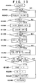
- FIGS. 1-6 illustrate a first embodiment of the invention:
- FIGS. 7-11 illustrate a second embodiment of the invention:
- FIGS. 12-15 illustrate a third embodiment of the invention:
- FIGS. 16-19 illustrate a fourth embodiment of the invention.
- an internal combustion engine capable of fuel combustion at lean air-fuel ratios has an exhaust conduit 6.
- An NOx absorption and release material 2 and an NOx decomposition catalyst 4 are disposed in the exhaust conduit 6 in that order in the direction of exhaust gas flow.
- An electric heater 24 operable to heat the NOx absorption and release material 2 is located in the exhaust conduit 6.
- the heater 24 is located upstream of and close to the NOx absorption and release material 2.
- a bypass conduit 8 bypassing the heater 24 and the NOx decomposition catalyst 4 is provided to the exhaust conduit 6.
- a bypass valve 10 is disposed at a diverging portion of the bypass conduit 8 and the exhaust conduit 6 to permit control of the ratio of the amount of exhaust gas flowing through the NOx absorption and release catalyst to the amount of exhaust gas flowing through the bypass conduit 8.
- Switching of the heater 24 between “ON” and “OFF” is controlled by an NOx absorption and release material regeneration means 26.
- Operation of the bypass valve 10 is controlled by a bypass valve control means 12.
- the heater 24 is switched to "ON” to heat the NOx absorption and release material 2.
- T0 the temperature T of the NOx absorption and release catalyst has exceeded a predetermined temperature T0, the bypass valve 10 throttles the exhaust gas flowing through the NOx absorption and release material 2 and the NOx decomposition catalyst 4 for a predetermined period, for example, ten seconds.
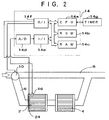
- FIG. 2 illustrates the system in more detail.
- an electronic control unit (ECU) 14 is constituted by a micro computer.
- the NOx absorption and release material regeneration means 26 and the bypass valve control means 12 comprise means defined in programs (see FIGS. 3 and 4) stored in the ECU 14.
- the ECU 14 includes a central processor unit (CPU) 14a for executing calculations, a read-only memory (ROM) 14b, a random access memory (RAM) 14c, an analog/digital converter 14d for converting analog signals to digital signals, an input interface 14e, and an output interface 14f.
- a timer (described later) 14g is connected to the ECU 14.
- an exhaust gas temperature sensor (or an NOx absorption and release material temperature sensor) 16 is installed in a portion of the exhaust conduit 6 downstream of the heater 24.
- the output of the sensor 16 is fed to the analog/digital converter 14d and is used as an exhaust gas temperature T in calculation.
- the results of the calculation executed at the CPU 14a are sent via the output interface 14f to the heater 24 and an actuator of the bypass valve 10 so that the heater 24 and the bypass valve 10 are controlled.
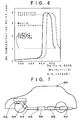
- the NOx absorption and release material 2 is disposed in a portion of the exhaust conduit where the exhaust gas temperature is lower than 500°C.
- Such an exhaust conduit portion is usually spaced apart from the engine 18 and is located under a floor of a vehicle 20, as shown in FIG. 5.
- a member denoted with reference numeral 22 is a muffler.
- the NOx absorption and release material 2 comprises a material capable of absorbing NOx included in exhaust gas at temperatures below a predetermined temperature (for example, 500°C) and releasing absorbed NOx at temperature above the predetermined temperature.
- a predetermined temperature for example, 500°C
- Such an NOx absorption and release material comprises a composite oxide of alkali earth and copper (Ba-Cu-O base), or a combination of rare-earth element and noble metal.
- the composite oxide of alkali earth and copper is, for example, MnO2.BaCuO2
- the combination of rare-earth element and noble metal is, for example, a combination of lanthanum (La) and platinum (Pt).
- the Ba-Cu-O base NOx absorption and release material converts NO into NO2 at temperatures below about 500°C and can absorb stably the converted NO2 in the crystal structure of the NOx absorption and release material.
- the Ba-Cu-O base NOx absorption and release material 2 loses its NOx absorption ability at temperatures above about 500°C and releases absorbed NO2, which the NOx absorption and release material 2 has absorbed for several hours, within a short period of time, for example, ten seconds.
- the Ba-Cu-O base NOx absorption and release material 2 is produced by the following methods:
- Equal moles of copper nitrate and barium nitrate were mixed and the mixture was calcined in air at 650°C for four hours. Then, the resulting sinstered mixture was placed into 8-platinum nitrate solution so that platinum was deposited onto the sintered mixture. Then, the platinum-coated mixture was roasted at 500°C in a flow of nitrogen.
- Equal moles of copper nitrate and barium nitrate were mixed and the mixture was calcined in air at 650°C for four hours. This sintered mixture was placed into cerium nitrate solution so that cerium was deposited onto the mixture. Then, the cerium-coated mixture was roasted at 500°C in a flow of air.
- Powder of one of the above-described roasted mixtures, silica-sol, and water were mixed at a ratio of 100 : 100 : 10 to produce a slurry.
- a monolith constructed of sintered cordierite was immersed in the slurry and then was taken out of the slurry and was dried in a stream of hot air at 250°C. This coating procedure was repeated several times, and then the coated monolith was roasted at 500°C to obtain an NOx absorption and release material.
- the NOx release characteristic shifts by 50 - 100°C toward the right (dashed line) in FIG. 6. From FIG.
- the Ba-Cu-O base NOx absorption and release material releases NOx under oxidizing gas conditions at lean air-fuel ratios above about 500°C, for example, when the heater is switched to "ON", and absorbs NOx at temperatures below about 500°C, for example, when the heater is switched to "OFF". Further, if the air-fuel ratio is changed to a stoichiometric air-fuel ratio or rich ratios, the exhaust gas approaches the non-oxygen condition and the NOx release characteristic shifts to a lower temperature so that NOx release is promoted.
- the NOx decomposition catalyst 4 comprises a transition metal/zeolite catalyst, a noble metal/alumina catalyst, or a cobalt/alumina catalyst.
- the transition metal/zeolite catalyst includes zeolite and a transition metal, for example copper, ion-exchanged and deposited onto the zeolite.
- the noble metal/alumina catalyst includes a carrier of alumina (Al2O3) and a noble metal, for example platinum, deposited onto the alumina carrier.
- the cobalt/alumina catalyst includes an alumina carrier and cobalt deposited onto the alumina carrier.
- the amount of HC should be appropriate, because too much HC would decrease the NOx decomposition rate of the catalyst.
- the space velocity should be low, because the NOx decomposition rate of the NOx absorption and release material is low at high space velocities. Therefore, when the heater 24 is switched to "ON" and the temperature of the exhaust gas at the NOx absorption and release material is higher than the predetermined temperature T0 (for example, 500°C), the bypass valve 10 should throttle the amount of exhaust gas flowing through the NOx absorption and release material 2 and the NOx decomposition catalyst 4 so that the space velocity at the NOx decomposition catalyst 4 is low.
- T0 for example, 500°C
- FIGS. 3 and 4 illustrate control routines for controlling the heater 24 and the bypass valve 10 so that the heater 24 is switched to "ON" to heat the NOx absorption and release material 2 at a predetermined condition and at the same time the bypass valve 10 throttles the amount of exhaust gas flowing through the NOx decomposition catalyst 4 to cause the NOx decomposition catalyst 4 to decompose NOx at a high rate.
- These routines are stored in the ROM 14b and are entered into the CPU 14a where calculations are executed.
- the control routines of FIGS. 3 and 4 are entered at intervals of predetermined periods or at every predetermined crank angle.
- the state that flag Fdb is "1” means that the heater 24 is in an "ON” state and the bypass valve 10 throttles the exhaust gas flowing through the NOx absorption and release material 2 and the NOx decomposition catalyst 4 and causes a large portion of the exhaust gas to flow through the bypass conduit 8.
- the state that flag Fdb is "0” means that the heater 24 is in an "OFF” state and all of the exhaust gas flows through the NOx absorption and release material 2 and the NOx decomposition catalyst 4.
- step 102 When it is determined at step 102 that flag Fdb is "1”, since the heater 24 is in an "ON” state and the bypass valve 10 is in a throttling operation, the heater 24 need not be switched to "ON” and the bypass valve 10 need not be changed in operation to throttle the amount of the exhaust gas flowing through the NOx absorption and release material 2 by causing the routine to proceed through steps 104 - 110. Thus, the routine proceeds directly to a return step. In contrast, when it is determined at step 102 that flag Fdb is "0”, the routine proceeds to step 102 where a decision is made as to whether rotation accumulation flag Fdg is "1" or not.
- the state that flag Fdg is "1" means that the accumulated engine rotations SNe counted since the last regeneration of the NOx absorption and release material 2 do not exceed a predetermined number of rotations SNe0 and the NOx absorption and release material 2 is not yet saturated.
- the state that flag Fdg is "0" means that SNe is larger than SNe0 and that the NOx absorption and release material 2 is already saturated or is going to be saturated.
- step 104 When it is determined at step 104 that flag Fdg is "1", since a long period has not elapsed since last release of NOx from the NOx absorption and release material 2, the NOx absorption and release material 2 need not be regenerated, and so the routine proceeds to the return step. In contrast, when it is determined at step 104 that flag Fdg is "0", the routine proceeds to step 104′, where the heater 24 is switched to "ON”. Then, the routine proceeds to step 106, where a decision is made as to whether or not the exhaust gas temperature (or NOx absorption and release material temperature) T which is raised through heating by the heater 24 exceeds a predetermined temperature T0.
- T0 is defined as a temperature forming a boundary between an NOx absorption temperature range and an NOx release temperature range, and T0 is about 500°C.
- step 106 When it is determined at step 106 that T is equal to or smaller than T0, since the NOx absorption and release material 2 has not yet been raised in temperature to an NOx release beginning temperature after the switching-on of the heater 24, the routine proceeds to the return step. In contrast, when it is determined at step 106 that T exceeds T0, the routine proceeds to steps 108 and 110 to control the bypass valve 10 so that the NOx decomposition catalyst 4 decomposes at high decomposition rates the NOx which the NOx absorption and release material 2 begins to release.
- step 110 Since the heater 24 is in an "ON" state and the bypass valve 10 is in a throttling condition when the routine proceeds through the route including steps 108 and step 110, flag Fdb is set to "1" at step 108. Then, the routine proceeds to step 110, where the bypass valve 10 is switched to throttle the exhaust gas flowing though the NOx absorption and release material 2 and the NOx decomposition catalyst 4, and then the timer 14g is switched on.
- the timer 14g is preset to switch off the heater 24, to clear the accumulated rotation SNe to zero, and to reset flag Fdb to "0", after about ten seconds has elapsed since the switching on of the timer 14g. Accordingly, the timer 14g maintains the heater 24 at an "ON" state for about ten seconds after the exhaust gas temperature T exceeds the predetermined temperature T0 subsequent to switching the heater on, so that NOx release from the NOx absorption and release material 2 is completed during the period of about ten seconds. After the period of ten seconds, flag Fdb is cleared and the timer 14g is reset.
- steps 104 and 104′ and the timer 14g constitute the NOx absorption and release material regeneration means 26, and steps 106 and 110 and the timer 14g constitute the bypass valve control means 12.
- the routine of FIG. 4 is a flag control routine for controlling flags Fdb and Fdg so that the heater 24 and the bypass valve 10 are prevented from operation before the NOx absorption and release material 2 is saturated, even though exhaust gas temperature T exceeds the predetermined temperature T0.
- the routine of FIG. 4 assures that exhaust gas flow through the bypass conduit 8 to atmosphere without being purified will not continue for a long period of time.
- step 202 a decision is made as to whether flag Fdb is "1". When it is determined at step 202 that flag Fdb is "0", the routine proceeds to step 204, where the number of engine rotations counted since last regeneration of the NOx absorption and release material 2 is increased by every entry to the routine of FIG. 4. When it is determined at step 202 that Fdb is "1", the routine proceeds directly to a return step.
- step 202 the routine proceeds from step 202 to 204, and the engine rotation number SNe is accumulated. Then, the routine proceeds to step 206, where a decision is made as to whether the accumulated rotation SNe exceeds the predetermined rotation SNe0. If SNe is equal to or less than SNe0 at step 202, the NOx absorption and release material 2 may be deemed to have not yet been saturated, and the routine proceeds to step 212, where flag Fdg is set to "1". If SNe exceeds SNe0 at step 202, the routine proceeds to steps 208 and 210 where flags Fdb and Fdg are set to "1" in preparation for execution of control according to the routine of FIG. 3.
- the NOx absorption and release material 2 releases the NOx which had been absorbed, so as to be finally regenerated.
- the bypass valve 10 throttles the exhaust gas flowing to the NOx decomposition catalyst 4 so that the space velocity at the NOx decomposition catalyst 4 is low and NOx is decomposed into N2 and O2 by the NOx decomposition catalyst 4 at high rates.
- an NOx absorption and release material 56 is installed in an exhaust conduit 54 of an internal combustion engine 52 capable of fuel combustion at lean air-fuel ratios.
- the exhaust conduit 54 comprises a single conduit.
- a three-way catalyst 58 may be installed in the exhaust conduit downstream of the NOx absorption and release material 56. Since the NOx absorption and release material 54 should be located in a portion of the exhaust conduit 54 where the exhaust gas temperature is below 500°C, the NOx absorption and release material 54 is located under a floor of a vehicle 60.
- another three-way catalyst 64 is installed in the exhaust conduit between the engine 52 and the NOx absorption and release material 56. The three-way catalyst 64 is located close to the engine 52.
- the NOx absorption and release material 56 comprises a material capable of absorbing NOx below a predetermined temperature (for example, 500°C) and of releasing absorbed NOx at temperatures above the predetermined temperature, and comprises, for example, Ba-Cu-O base material.
- the three-way catalyst 58 can purify NOx, CO (carbon monoxide), and HC (hydrocarbons) included in exhaust gas at a stoichiometric or rich air-fuel ratio. However, at lean air-fuel ratios, the three-way catalyst 58 cannot purify NOx and can purify CO and HC only.
- the three-way catalyst 64 disposed between the engine 52 and the NOx absorption and release material 56 functions as a cold catalyst. More particularly, in a cold period immediately after engine start a large amount of HC is exhausted from the engine. Since the three-way catalyst 58 disposed in a downstream portion of the exhaust conduit has not yet been warmed-up to the activation temperature of about 250°C, the three-way catalyst 58 can not purify the great amount of HC following a cold start. To purify the cold HC, the three-way catalyst 64 is disposed close to the engine so that the three-way catalyst 64 is quickly warmed-up and HC can be purified quickly.
- the three-way catalyst 64 is preferably provided is to suppress HC degradation of the NOx absorption and release material 56.
- the larger the amount of HC the lower is the NOx absorption ability of the NOx absorption and release material 56. This is because even if the NOx absorption and release material converts NO into NO2 to absorb NO2, the converted NO2 is reduced to NO by HC, and NO cannot be absorbed by the NOx absorption and release material 56.
- the NOx absorption and release material 56 and the three-way catalyst 58 are combined so as to purify NOx, when a lean burn and low temperature operation continues for a long time period, the NOx absorption and release material 56 will finally be saturated and lose its NOx absorption ability.
- the NOx which has not been purified at the saturated NOx absorption and release material 56 will flow to the three-way catalyst 58, which cannot purify NOx under oxidizing conditions, and then is exhausted as it is to atmosphere.
- the heater control apparatus shown in FIG. 8 and the heater control steps shown in FIGS. 9 - 11 are provided in the second embodiment of the invention.
- an electronic control unit (ECU) 66 constituted by a micro computer includes a central processor unit (CPU) 66a, a read-only memory (ROM) 66b, a random access memory (RAM) 66c, an input interface (I/I) 66d, an output interface (I/O) 66e, and an analog/digital converter (A/D) 66f.
- CPU central processor unit
- ROM read-only memory
- RAM random access memory
- I/I input interface
- I/O output interface
- A/D analog/digital converter
- An intake pressure sensor 78 is installed in an intake conduit 79 downstream of a throttle valve 82 and generates an electric signal PM corresponding to an intake pressure PM.
- a crank angle sensor 76 is housed in a distributor and generates an electric signal which is used for calculation of engine speed NE.
- an exhaust gas temperature sensor (or NOx absorption and release material temperature sensor) 72 is installed downstream of the heater 84 and generates an electric signal corresponding to the exhaust gas temperature T.
- An oxygen sensor 74 also is provided in the exhaust conduit. Analog signals among these signals are converted into digital signals by the A/D converter 66f and then fed to the input interface 66d. Digital signals are fed to the input interface 66d as they are.
- the instructions from the CPU 66a are sent through the output interface 66e to respective members, for example, the heater 84 and a fuel injection valve 80.
- the ROM 66b stores the routines of FIGS. 9 and 10 which are read by the CPU 66a, where control calculation is executed.
- the routines of FIGS. 9 and 10 control the heater 84 so that when a lean burn condition continues for a first predetermined time period, the heater 84 is switched on and is maintained in an "ON" state for a second predetermined time period.
- the routines of FIGS. 9 and 10 further control the fuel injector to provide a stoichiometric or rich air-fuel ratio during the "ON" state of the heater.
- the control routine of FIG. 9 is entered at predetermined intervals.
- a decision is made as to whether release requirement flag Fd is "1" or not.
- the state that flag Fd is "1” means the NOx absorption and release material 56 is close to saturation and needs to be regenerated.
- the routine proceeds to a return step, skipping steps 304 - 316. In a standard operation, flag Fd is in a "0" state due to step 410 as described later.
- step 302 When flag Fd is "0" at step 302, that is, the NOx absorption and release material 56 is not yet saturated, the routine proceeds to step 304, where a time of a continuing lean burn condition is counted up per every entry to the routine, for example by increasing the accumulated engine rotations.
- step 306 a decision is made as to whether or not the period of continuing lean burn condition, as measured by accumulated engine rotations SNe, finally exceed a predetermined number of rotations SNe0.
- SNe exceeds SNe0, it is deemed that NOx absorption ability of the NOx absorption and release material 56 reaches the limit and the NOx absorption and release material 56 must be regenerated.
- the routine proceeds to step 308 where flag Fd is set to "1". If SNe is smaller than SNe0 at step 306, the routine proceeds to step 312. Since SNe is usually smaller than SNe0, the routine usually proceeds to step 312.
- steps 304 and 306 constitute a decision means for determining whether a lean burn condition has continued for a first predetermined time period.
- step 310 a decision is made as to whether or not flag Fds is "1".
- the state that flag Fds is "1" means that the NOx absorption and release material is in a natural release condition.
- the routine proceeds to the return step. If flag Fds is "0" at step 310, the routine proceeds to step 312, where a decision is made as to whether or not the exhaust gas temperature T is higher than a natural release beginning temperature T2 at which the NOx absorption and release material 56 begins to release NOx naturally under oxidizing gas conditions.
- step 314 natural release range flag Fds is set to "1"
- step 306 the second timer 70 is switched to "ON".
- SNe is cleared to zero and flag Fds also is cleared to "0".
- the NOx absorption and release material 56 continues to release NOx under oxidizing gas conditions, so that the NOx absorption and release material 56 is finally regenerated. If the exhaust gas temperature T is lower than T2 at step 312, the routine proceeds to the return step, skipping steps 314 and 316.
- step 402 a decision is made as to whether or not release requirement flag Fd is "1". Usually, flag Fd is in a "0" condition due to step 410 which will be described later. If flag Fd is "0" at step 402, the routine proceeds to a return step. In contrast, if flag Fd is "1" at step 402, the routine proceeds to step 402′, where the heater 84 is switched on. Then, the routine proceeds to step 404.
- flag Fdg is "0"
- the routine proceeds to step 408 so that the air-fuel ratio is controlled to a stoichiometric or rich air-fuel ratio, and flag Fdg is set to "1". If flag Fdg is "1" at step 406, since the engine operation is in the stoichiometric control condition, the routine proceeds to the return step.
- step 408 the routine proceeds to step 410, where the first timer 68 is switched to "ON".
- the first timer 68 counts a second time period, for example, twenty seconds, and after the second period, clears the accumulated engine rotations number SNe, resets stoichiometric release flag Fdg and release requirement flag Fd, and switches off the heater 84. Then, the routine returns.
- step 402′ and the first timer 68 constitute the NOx absorption and release material regeneration means. Further, steps 402, 408, and 410 constitute air-fuel ratio control means for temporarily changing the air-fuel ratio to a stoichiometric or rich air-fuel ratio for a predetermined period set by the first timer 68 (for example, twenty seconds).
- Fuel injection control itself is well known. More particularly, a basic fuel injection amount TAU is determined on the basis of an engine load PM and an engine speed NE, and then various modifications are added to the TAU value. To determine TAU on the basis of PM and NE, two maps are stored in the ECU, that is, a lean burn map used for lean burn operation and a stoichiometric map used for stoichiometric operation.
- the stoichiometric map control of step 408 means that the operation is temporarily changed from the lean burn operation to a stoichiometric operation using the stoichiometric map.
- the three-way catalyst 58 cannot reduce NOx.
- the NOx absorption and release material 56 is located under a vehicle floor, the temperature of the NOx absorption and release material 56 is low, so that NOx included in exhaust gas is absorbed by the NOx absorption and release material 56. As a result, NOx exhaust into the atmosphere is prevented.
- the heater 84 is switched to "ON" so that the engine is changed to a stoichiometric air-fuel ratio operation where the three-way catalyst 58 can reduce NOx. Since the heater 84 has been switched on, the temperature of the NOx absorption and release material 56 rises and finally exceeds the predetermined temperature, to release absorbed NOx. The released NOx is reduced by the three-way catalyst 58 which is located downstream of the NOx absorption and release material 56.
- flag Fd is set to "1" at step 308.
- the routine of FIG. 10 proceeds to steps 402′, 408, and 410, so that the heater 84 is changed to "ON" and the air-fuel ratio is changed to a stoichiometric or rich air-fuel ratio. This condition is maintained for a second time period.
- the NOx release characteristic is changed from T2 to T1 in FIG. 11, and the NOx absorption and release material 56 releases NOx and is regenerated. After the regeneration, the operation is returned to a lean burn operation. These cycles are repeated.
- an exhaust conduit 30 of a lean burn engine includes a dual passage portion 32 having a first passage 32A and a parallel second passage 32B.
- Diesel particulate filter and NOx absorption and release materials (hereinafter, NOx absorption and release materials) 34A and 34B are disposed in first and second passages 32A and 32B, respectively.
- NOx absorption and release materials 34A, 34B functions not only as a diesel particulate filter for capturing diesel particulates but also as an NOx absorption and release material. More particularly, each NOx absorption and release material 34A, 34B absorbs NOx included in exhaust gas from the engine at temperatures below a predetermined temperature and releases absorbed NOx at temperatures above the predetermined temperature.
- Each NOx absorption and release material 34A, 34B includes a carrier constituted of alumina which carries at least one kind of material selected from the group consisting of alkali metal including potassium (K), sodium (Na), and lithium (Li); alkali-earth including barium (Ba), cesium (Ce), and calcium (Ca); and rare-earth element including lanthanum (La) and yttrium (Y), and further carries at least one kind of metal selected from the group consisting of noble metals including platinum (Pt) and transition metals including copper (Cu) and iron (Fe).
- This NOx absorption and release material absorbs NOx when the exhaust gas is in oxidizing gas conditions, and releases NOx when the oxygen concentration of the exhaust gas decreases and/or when the the exhaust gas temperature rises to a temperature above the predetermined temperature.
- NOx decomposition catalysts 36A and 36B with a heater are disposed in portions of the first and second passages 32A and 32B, respectively, located downstream of the NOx absorption and release materials 34A and 34B.
- any of the following three kinds of catalysts can be used: a catalyst which is constituted by zeolite ZSM-5 and copper ion-exchanged and deposited onto the zeolite; a catalyst which is constituted by alumina Al2O3 and Cu deposited onto the alumina; and a catalyst which is constituted by alumina Al2O3 and platinum or platinum and rhodium deposited onto the alumina.
- Electric heaters 38A and 38B are disposed in portions of the first and second passages 32A and 32B, respectively, located upstream of the NOx absorption and release materials 34A and 34B.
- the heaters 38A and 38B burn diesel particulates captured by the NOx absorption and release materials 34A and 34B, and heat the NOx absorption and release material 34A and 34B to a temperature above the predetermined temperature to cause the NOx absorption and release material 34A and 34B to release absorbed NOx.
- the NOx absorption and release materials 34A and 34B are regenerated both as a diesel particulate filter and as an NOx absorption material.
- Flow switching valves 40A and 40B for switching exhaust gas flow between the first passage 32A and the second passage 32B are disposed in the first and second passages 32A and 32B, respectively, upstream of the heaters 38A and 38B, respectively.
- the flow switching valves 40A and 40B are driven by actuators 42A and 42B, respectively. When one of the switching valves 40A and 40B is open, the other of the switching valves 40A and 40B is closed.
- Secondary air supply ports 46A and 46B for supplying secondary air into the first and second passages 32A and 32B are provided at portions of the first and second passages 32A and 32B located between the switching valves 40A and 40B and the NOx absorption and release materials 34A and 34B.
- the secondary air supply ports 46A and 46B are connected to an air pump 50 via secondary air conduits in which solenoid valves 48A and 48B for switching on and off supply of secondary air are disposed.
- the heaters 38A and 38B provided so as to heat the NOx absorption and release materials 34A and 34B and the heaters provided so as to heat the NOx decomposition catalysts 36A and 36B are connected via an electric circuit to a battery 86 so that electricity is supplied to the heaters, and an electric relay device 88 is provided on the electric circuit so as to selectively switch on and off the heaters.
- the switching on and off of the flow switching valves 40A and 40B and the switching on and off of the electric heaters for the NOx decomposition catalysts 38A and 38B are controlled by an electronic control unit (ECU) 90.
- the ECU 90 includes a CPU, a ROM, a RAM, and input and output interfaces, and analog signals are converted into digital signals by an A/D converter and are fed to the input interface.
- a pressure sensor 92 is installed in a portion of the exhaust conduit 30 located upstream of the dual passage portion 32 and another pressure sensor 94 is installed in a portion of the exhaust conduit 30 located downstream of the dual passage portion 32.
- a differential between outputs of these two pressure sensors 92 and 94 corresponds to the amount of diesel particulates captured by the NOx absorption and release materials 34A and 34B, so that the need for regeneration as a diesel particulate filter can be detected.
- the outputs of the pressure sensors 92 and 94 are fed to the ECU 90.
- Output signals of the engine speed sensor 96 and the engine load sensor 98 are also fed to the ECU 90.
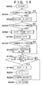
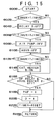
- Control routines of FIGS. 13 - 15 for controlling the flow switching valves 40A and 40B and heaters 38A and 38B are stored in the ROM, and calculation according to the control routines is executed in the CPU.
- the routine of FIG. 13 controls beginning regeneration of the NOx absorption and release material, and the routines of FIGS. 14 and 15 control the regeneration operation periods using a timer to perform regeneration and then resetting at optimum timings.
- the routine of FIG. 13 is entered at step 500 at intervals of predetermined periods, for example, at every eight milliseconds.
- the current engine speed Ne, the current engine load T (for example, throttle valve opening degree), the current pressure Pa of the pressure sensor 92, and the current pressure Pb of the pressure sensor 94 are entered.
- a predetermined allowable pressure differential Pd between the upstream side and the downstream side of the NOx absorption and release material for the current engine operating condition is determined using a map.
- a decision is made as to whether or not the current pressure differential (Pa - Pb) exceeds the allowable pressure differential Pd.
- the routine proceeds to a return step.
- the routine proceeds to step 508 to regenerate the NOx absorption and release material by burning diesel particulates.
- the condition that passage A flag PAF is "1” means valve 40a is currently open so that the exhaust gas has been flowing through the first passage 32A, and therefore the NOx absorption and release material to be regenerated is the NOx absorption and release material 34A. If it is determined at step 508 that flag PAF is "1", the routine proceeds to step 510A, where a decision is made as to whether or not the current cycle is a first cycle for passing through the route including step 510A. The condition that flag C is "1" corresponds to the first cycle.
- step 510A When it is determined at step 510A that flag C is "1", the routine proceeds to steps 512A - 522A, where regeneration of the NOx absorption and release material 34A begins. More particularly, at step 512A the flow switching valve 40A is closed, at step 514A the timer is switched on, at step 516A the air pump 50 is turned on, and at step 518A the heater of the NOx decomposition catalyst 36A is switched on by operating the relay 88. As a result, the heater 38A burns the particulates to regenerate the NOx absorption and release material. During the regeneration, secondary air supplied from the air pump 50 flows through the NOx absorption and release material 34A at low speeds. Since the temperature of the exhaust gas flowing through the NOx absorption and release material is high due to combustion energy of the particulates, the NOx absorption and release material 34A releases absorbed NOx.
- step 524A flag C is set to "0", and then the routine proceeds to step 526 where the cycle ends.
- the routine will proceed from step 51A to step 526.
- the regeneration by steps 512A - 524A of the previous cycle holds until the regeneration has been completed in the routines of FIGS. 14 and 15.
- step 508 If it is determined at step 508 that passage A flag PAF is "0", this means valve 40a is currently shut so that the exhaust gas has been flowing through the passage 32B, and the NOx absorption and release material to be regenerated is the NOx absorption and release material 34B. Thus, the routine proceeds from step 508B to step 510B so that regeneration of the NOx absorption and release material 34B is executed. Structures and functions of steps 510B - 524B are the same as those of steps 510A - 524A except that suffix A of each reference numeral is changed to B.
- the regeneration of the NOx absorption and release material 34A continues for a predetermined period according to the routine of FIG. 14.
- the routine of FIG. 14 is entered at step 600A at intervals of predetermined periods, for example, at every eight milliseconds.
- a decision is made as to whether the timer count time exceeds a predetermined period T1 (for example, three minutes). If the timer count time exceeds the predetermined period T1 at step 602A, the routine proceeds to step 604A, where the relay 88 is switched off to switch off the heater 38A. Then, the routine proceeds to step 606A, where a decision is made as to whether the timer count time exceeds a predetermined period T2 (for example, fifteen minutes).
- step 608A the air pump 50 and the air switching valve 48A are switched off, so that supply of secondary air stops.
- the routine proceeds to step 612A, where a decision is made as to whether or not a timer count time exceeds a predetermined period T3 (for example, fifteen minutes). If the timer count time exceeds the period T3, the routine proceeds to step 614A, where the heater provided to the NOx decomposition catalyst 36A is switched off. In this way, when the period of the maximum of T1, T2, and T3 has elapsed, the regeneration is completed.
- step 616A a decision is made as to whether or not all of the relay 88, the air pump 50, the air switching valve 48A, and the heater 36A are switched off, that is, whether or not the regeneration has been completed. If the regeneration has not yet been completed, the routine proceeds to a return step 624A, and if the regeneration has been completed, the routine proceeds to steps 618A - 622A, where passage A flag PAF is reset to "0", flag C is reset to "1", and the timer count time is cleared to zero.
- Steps 600B - 624B of the routine of FIG. 15 correspond to steps 600A - 624A of the routine of FIG. 14 except that suffix A is changed to suffice B.
- the routines of FIGS. 13, 14, and 15 constitute the NOx absorption and release material regeneration means of the third embodiment of the invention.
- the NOx absorption and release material 34A, 34B When the temperature of the NOx absorption and release material 34A, 34B is high due to the thermal energy which the captured diesel particulates produces when burned, the NOx absorption and release material 34A, 34B releases absorbed NOx. The released NOx flows to the NOx decomposition catalyst 36A, 36B where the NOx is decomposed. Thus, the NOx absorption and release material 34A, 34B is regenerated not only as a captured diesel particulate filter and but also as an NOx absorption material. In the third embodiment, since flow through the NOx absorption and release material 34A, 34B during regeneration is at a low space velocity and at a high temperature, the regeneration is smooth. Consequently, one of the NOx absorption and release materials 34A, 34B is always in a non-saturated condition capable of absorbing NOx, so NOx exhaust to atmosphere is always prevented.
- an apparatus according to the fourth embodiment of the invention comprises an apparatus where a reduction agent such as hydrocarbons (HC) and hydrogen is supplied into the passage upstream of the NOx decomposition catalyst 36A, 36B in an apparatus otherwise similar to that of the third embodiment, so that NOx conversion rate of the NOx decomposition catalyst 36A, 36B is increased.
- a reduction agent such as hydrocarbons (HC) and hydrogen
- an HC injection apparatus for injecting fuel (light oil) of the diesel engine into the exhaust conduit is installed.
- the HC injection apparatus includes an HC supply valve 28A, 28B which supplies HC when it is open. Opening and closing of the HC supply valve 28A, 28B is controlled by the ECU 90.
- FIGS. 17 - 19 illustrate routines for controlling regeneration of the NOx absorption and release materials 34A and 34B, which constitute the NOx absorption and release material regeneration means of the fourth embodiment of the invention.
- the routines of FIGS. 17 - 19 are the same as those of FIGS. 13 - 15, respectively, except that steps 700A, 700B, 702A, 704A, 702B, 704B are added in the routines of FIGS. 17 - 19.
- step 700A is added between step 522A and step 524A.
- HC supply valve 28A is opened so that HC is supplied.
- the NOx decomposition catalyst 36A, 36B needs HC as a reduction agent to decompose NOx.
- the supplied HC helps the released NOx to be decomposed at the NOx decomposition catalyst 36A.
- step 700B is added between step 522B and 524B.
- HC supply valve 28B is opened so that HC is supplied.
- the supplied HC helps the released NOx to be decomposed at the NOx decomposition catalyst 36B.
- steps 702A and 703A are added between step 614A and 616A.
- T4 for example, fifteen minutes
- the HC supply valve 28A is switched off and supply of HC is stopped.
- steps 702B and 704B are added and supply of HC is stopped by switching off the HC supply valve 28B.
- the NOx conversion rate of the NOx decomposition catalysts 36A and 36B is increased to a great extent. More particularly, injected HC is thermally decomposed into HC of desirable sizes which is partially oxidized to generate radicals to promote decomposition of NOx at the NOx decomposition catalysts 36A and 36B.
- the NOx absorption and release material 34A, 34B begins to release absorbed NOx not only when the exhaust gas temperature exceeds a predetermined temperature but also when the oxygen concentration of the exhaust gas lowers.
- the exhaust gas includes almost no oxygen while unburned HC increases.
- the unburned HC is consumed in decomposing NOx, because the HC rapidly takes oxygen atoms from the NOx that is released from the NOx absorption and release material to be oxidized. Since the NOx absorption and release materials 34A and 34B have an NOx absorption characteristic under a lean burn condition and an NOx decomposition characteristic at low oxygen concentrations, the NOx decomposition catalysts 36A and 36B are not absolutely necessary in this embodiment.
- the temperature of the NOx absorption and release material can be intentionally controlled independently of the engine operating condition and the location of the NOx absorption and release material, so that controllability and freedom of design are improved.
Applications Claiming Priority (4)
| Application Number | Priority Date | Filing Date | Title |
|---|---|---|---|
| JP308245/91 | 1991-10-29 | ||
| JP30824591 | 1991-10-29 | ||
| JP4219145A JP2783074B2 (ja) | 1991-10-29 | 1992-08-18 | 内燃機関の排気浄化装置 |
| JP219145/92 | 1992-08-18 |
Publications (2)
| Publication Number | Publication Date |
|---|---|
| EP0540280A1 true EP0540280A1 (de) | 1993-05-05 |
| EP0540280B1 EP0540280B1 (de) | 1995-10-11 |
Family
ID=26522949
Family Applications (1)
| Application Number | Title | Priority Date | Filing Date |
|---|---|---|---|
| EP92309801A Expired - Lifetime EP0540280B1 (de) | 1991-10-29 | 1992-10-26 | Einrichtung zur Minderung von Stickoxiden in Rauchgasen aus Brennkraftmaschinen |
Country Status (4)
| Country | Link |
|---|---|
| US (1) | US5388406A (de) |
| EP (1) | EP0540280B1 (de) |
| JP (1) | JP2783074B2 (de) |
| DE (1) | DE69205389T2 (de) |
Cited By (41)
| Publication number | Priority date | Publication date | Assignee | Title |
|---|---|---|---|---|
| EP0560991A1 (de) * | 1991-10-03 | 1993-09-22 | Toyota Jidosha Kabushiki Kaisha | Gerät zum reinigen von verbrennungsmotor-abgasen |
| EP0656809A1 (de) * | 1992-08-26 | 1995-06-14 | University Of Delaware | VERFAHREN ZUR ENTFERNUNG VON NOx AUS GASEN DER VERBRENNUNSZONE DURCH ABSORPTION |
| EP0666102A1 (de) * | 1994-02-04 | 1995-08-09 | Toyota Jidosha Kabushiki Kaisha | Verfahren zum Reinigen von Abgasen |
| DE19604318A1 (de) * | 1996-02-07 | 1997-08-14 | Man Nutzfahrzeuge Ag | Verfahren zur Regenerierung eines NO¶x¶-Speicherkatalysators |
| EP0791390A1 (de) * | 1996-02-23 | 1997-08-27 | Daimler-Benz Aktiengesellschaft | Verfahren und Vorrichtung zur katalytischen Gasreinigung |
| WO1997043031A2 (en) * | 1996-05-13 | 1997-11-20 | Engelhard Corporation | METHOD AND APPARATUS FOR NOx ABATEMENT IN LEAN GASEOUS STREAMS |
| WO1998007497A1 (de) * | 1996-08-19 | 1998-02-26 | Volkswagen Aktiengesellschaft | FREMDGEZÜNDETE BRENNKRAFTMASCHINE MIT EINEM NOx-ADSORBER |
| WO1998007504A1 (de) | 1996-08-19 | 1998-02-26 | Volkswagen Aktiengesellschaft | NOx-ABSORBER |
| EP0856645A1 (de) * | 1997-01-30 | 1998-08-05 | Ford Global Technologies, Inc. | Verfahren zur Regelung der Temperatur einer Katalysatoranordnung sowie Vorrichtung zur Durchführung des Verfahrens |
| WO1998045582A1 (en) * | 1997-04-08 | 1998-10-15 | Engelhard Corporation | Apparatus, method, and system for concentrating adsorbable pollutants and abatement thereof |
| FR2764637A1 (fr) * | 1997-06-16 | 1998-12-18 | Inst Francais Du Petrole | Procede et ensemble d'elimination des oxydes d'azote presents dans des gaz d'echappement, utilisant un moyen de piegeage des oxydes d'azote |
| US5851501A (en) * | 1995-05-09 | 1998-12-22 | Daimler-Benz Ag | Process for absorbing and desorbing nitrogen oxides in exhaust gases |
| EP0908225A2 (de) * | 1995-06-23 | 1999-04-14 | Ngk Insulators, Ltd. | Verfahren und Vorrichtung zur Abgasreinigung |
| US5968462A (en) * | 1994-02-04 | 1999-10-19 | Toyota Jidosha Kabushiki Kaisha | Process for purifying exhaust gases |
| DE19817650A1 (de) * | 1998-04-21 | 1999-11-04 | Ford Werke Ag | Verfahren und Vorrichtung zur Regelung der Temperatur einer Abgasbehandlungsanordnung |
| US6010673A (en) * | 1992-09-21 | 2000-01-04 | Toyota Jidosha Kabushiki Kaisha | Method for purifying exhaust gas |
| EP0976915A2 (de) * | 1998-07-28 | 2000-02-02 | Toyota Jidosha Kabushiki Kaisha | Abgasreinigungsvorrichtung |
| US6080377A (en) * | 1995-04-27 | 2000-06-27 | Engelhard Corporation | Method of abating NOx and a catalytic material therefor |
| EP0946256A4 (de) * | 1996-08-19 | 2000-09-27 | Regents Of The | Plasmaunterstütztes katalytisches reduktonssystem |
| WO2000071863A1 (de) * | 1999-05-20 | 2000-11-30 | Oberland Mangold Gmbh | Heizelement zum beheizen strömender gase |
| EP1072764A1 (de) * | 1999-07-28 | 2001-01-31 | Renault | Vorrichtung und Verfahren zur Behandlung von Abgasen eines Verbrennungsmotors |
| FR2796984A1 (fr) * | 1999-07-28 | 2001-02-02 | Renault | Systeme de regeneration d'un piege a oxydes d'azote |
| EP0582917B1 (de) * | 1992-08-04 | 2001-11-07 | Toyota Jidosha Kabushiki Kaisha | Vorrichtung zur Reinigung von Abgas eines Motors |
| WO2001094760A1 (en) * | 2000-06-06 | 2001-12-13 | Johnson Matthey Public Limited Company | DIESEL EXHAUST SYSTEM INCLUDING NOx-TRAP |
| FR2810369A1 (fr) * | 2000-06-15 | 2001-12-21 | Toyota Motor Co Ltd | Dispositif de chauffage pour un moteur a combustion interne et son procede de controle |
| EP0896136A3 (de) * | 1997-08-05 | 2002-04-03 | Toyota Jidosha Kabushiki Kaisha | Vorrichtung zur Reaktivierung des Katalysators einer Brennkraftmaschine |
| EP1223312A1 (de) * | 2001-01-12 | 2002-07-17 | Renault | Abgasnachbehandlungssystem für einen Verbrennungsmotor und Verfahren zur Regelung eines solchen Systems |
| EP1055806A3 (de) * | 1999-05-28 | 2003-03-12 | Ford Global Technologies, Inc. | Stickoxidfalle und Partikelfilter für eine Brennkraftmaschine |
| EP0839996B1 (de) * | 1996-11-01 | 2003-09-03 | Toyota Jidosha Kabushiki Kaisha | Abgasreinigungsvorrichtung für Motor |
| US6696389B1 (en) | 1996-02-23 | 2004-02-24 | Daimlerchrysler Ag | Process and apparatus for cleaning a gas flow |
| EP1449575A1 (de) * | 2003-02-19 | 2004-08-25 | Isuzu Motors Limited | Verfahren zur Regeneration eines NOx Katalysators in einer NOx Reinigungsanlage und NOx Reinigungsanlage |
| US6823657B1 (en) | 1997-12-22 | 2004-11-30 | Volkswagen Ag | Regeneration of a NOx storage catalytic converter of an internal combustion engine |
| WO2005088091A1 (de) * | 2004-03-17 | 2005-09-22 | Gm Global Technology Operations, Inc. | Verfahren zur verbesserung der wirksamkeit der nox-reduktion in kraftfahrzeugen |
| WO2005106219A1 (en) * | 2004-05-05 | 2005-11-10 | Eaton Corporation | Temperature swing adsorption and selective catalytic reduction nox removal system |
| EP1505285A3 (de) * | 1997-12-04 | 2006-08-30 | DaimlerChrysler AG | Abgaskonvertersystem für einen Dieselmotor |
| WO2007005254A2 (en) * | 2005-06-30 | 2007-01-11 | General Electric Company | Method and system for regeneration of a catalyst |
| US7210288B2 (en) | 2003-01-02 | 2007-05-01 | Daimlerchrysler Ag | Exhaust gas aftertreatment installation and method |
| GB2478132A (en) * | 2010-02-25 | 2011-08-31 | Gm Global Tech Operations Inc | Device to reduce NOx for all driving profiles at both low and high exhaust temperatures. |
| CN101787916B (zh) * | 2009-01-23 | 2012-07-04 | 通用汽车环球科技运作公司 | 颗粒物质过滤器再生系统和方法 |
| CN101676528B (zh) * | 2008-08-12 | 2015-04-01 | 曼卡车和巴士股份公司 | 用于再生安装在内燃机废气管路中的颗粒过滤器的方法和设备 |
| CN110917869A (zh) * | 2018-09-20 | 2020-03-27 | 中国石油化工股份有限公司 | 一种降低催化裂化过程中不完全再生烟气中NOx排放量的方法 |
Families Citing this family (54)
| Publication number | Priority date | Publication date | Assignee | Title |
|---|---|---|---|---|
| EP0613714B1 (de) * | 1993-01-11 | 2001-07-04 | Toyota Jidosha Kabushiki Kaisha | Verfahren zur Reinigung von Abgasen |
| EP0636770B1 (de) * | 1993-01-19 | 1999-09-08 | Toyota Jidosha Kabushiki Kaisha | Abgasreinigungsgerät für eine brennkraftmaschine |
| CA2138133C (en) * | 1993-04-28 | 2002-04-23 | Kazuo Tsuchitani | Method for removal of nitrogen oxides from exhaust gas |
| JP3291086B2 (ja) * | 1993-09-24 | 2002-06-10 | トヨタ自動車株式会社 | 排ガス浄化用触媒及び排ガス浄化方法 |
| JP3409894B2 (ja) * | 1993-11-17 | 2003-05-26 | トヨタ自動車株式会社 | 排ガス浄化用触媒及び排ガス浄化方法 |
| JP3344040B2 (ja) * | 1993-11-25 | 2002-11-11 | トヨタ自動車株式会社 | 内燃機関の排気浄化装置 |
| EP0664147B1 (de) | 1994-01-20 | 1998-07-22 | Toyota Jidosha Kabushiki Kaisha | Katalysator zur Reinigung von Abgasen |
| JP3363564B2 (ja) * | 1994-02-04 | 2003-01-08 | トヨタ自動車株式会社 | 排ガス浄化用触媒 |
| JP3119088B2 (ja) | 1994-09-16 | 2000-12-18 | トヨタ自動車株式会社 | 内燃機関の排気浄化装置 |
| EP0707882A1 (de) * | 1994-10-21 | 1996-04-24 | Toyota Jidosha Kabushiki Kaisha | Katalysator zum Reinigen von Abgasen |
| GB9511412D0 (en) * | 1995-06-06 | 1995-08-02 | Johnson Matthey Plc | Improvements in emission control |
| US5656244A (en) * | 1995-11-02 | 1997-08-12 | Energy And Environmental Research Corporation | System for reducing NOx from mobile source engine exhaust |
| DE19607862C2 (de) * | 1996-03-01 | 1998-10-29 | Volkswagen Ag | Verfahren und Vorrichtungen zur Abgasreinigung |
| DE69824847T2 (de) | 1997-04-24 | 2005-07-07 | Toyota Jidosha K.K., Toyota | Abgasüberwachungssystem für verbrennungsmotoren |
| DE19747670C1 (de) * | 1997-10-29 | 1998-12-10 | Daimler Benz Ag | Abgasreinigungsanlage für eine Brennkraftmaschine |
| US6033461A (en) * | 1998-01-02 | 2000-03-07 | Gas Research Institute | Selective nitrogen oxides adsorption from hot gas mixtures and thermal release by adsorbent |
| JP3546294B2 (ja) * | 1998-04-28 | 2004-07-21 | トヨタ自動車株式会社 | 内燃機関の排気浄化装置 |
| US6125629A (en) * | 1998-11-13 | 2000-10-03 | Engelhard Corporation | Staged reductant injection for improved NOx reduction |
| FR2787037B1 (fr) * | 1998-12-09 | 2002-01-11 | Inst Francais Du Petrole | Procede et dispositif d'elimination des oxydes d'azote dans une ligne d'echappement de moteur a combustion interne |
| JP3680650B2 (ja) * | 1999-01-25 | 2005-08-10 | トヨタ自動車株式会社 | 内燃機関の排気浄化装置 |
| US6182443B1 (en) * | 1999-02-09 | 2001-02-06 | Ford Global Technologies, Inc. | Method for converting exhaust gases from a diesel engine using nitrogen oxide absorbent |
| US6497092B1 (en) * | 1999-03-18 | 2002-12-24 | Delphi Technologies, Inc. | NOx absorber diagnostics and automotive exhaust control system utilizing the same |
| US6497848B1 (en) | 1999-04-02 | 2002-12-24 | Engelhard Corporation | Catalytic trap with potassium component and method of using the same |
| US6199375B1 (en) * | 1999-08-24 | 2001-03-13 | Ford Global Technologies, Inc. | Lean catalyst and particulate filter control system and method |
| US6594991B2 (en) * | 2000-03-27 | 2003-07-22 | Toyota Jidosha Kabushiki Kaisha | Exhaust purifying method and apparatus of an internal combustion engine |
| FR2806754B1 (fr) * | 2000-03-27 | 2006-04-14 | Toyota Motor Co Ltd | Dispositif pour purifier le gaz d'echappement d'un moteur a combustion interne |
| FI114731B (fi) * | 2000-07-05 | 2004-12-15 | Kemira Metalkat Oy | Järjestelmä ja menetelmä pakokaasujen puhdistamiseksi |
| JP3794468B2 (ja) * | 2000-12-19 | 2006-07-05 | 三菱電機株式会社 | 内燃機関の排気ガス浄化装置 |
| JP3826357B2 (ja) | 2001-02-19 | 2006-09-27 | トヨタ自動車株式会社 | 水素生成触媒及び排ガス浄化用触媒 |
| JP2002309928A (ja) * | 2001-04-13 | 2002-10-23 | Yanmar Diesel Engine Co Ltd | 内燃機関の排気浄化装置 |
| US6820417B2 (en) * | 2001-11-29 | 2004-11-23 | Analytical Engineering, Inc. | Exhaust aftertreatment system and method for an internal combustion engine |
| US6813882B2 (en) | 2001-12-18 | 2004-11-09 | Ford Global Technologies, Llc | System and method for removing NOx from an emission control device |
| CA2422188A1 (en) * | 2002-10-02 | 2004-04-02 | Westport Research Inc. | Bypass controlled regeneration of nox adsorbers |
| JP2004162626A (ja) * | 2002-11-14 | 2004-06-10 | Hitachi Ltd | 排ガス浄化装置 |
| US6779339B1 (en) * | 2003-05-02 | 2004-08-24 | The United States Of America As Represented By The Environmental Protection Agency | Method for NOx adsorber desulfation in a multi-path exhaust system |
| JP2005090450A (ja) * | 2003-09-19 | 2005-04-07 | Hino Motors Ltd | 排気浄化装置 |
| US7900441B2 (en) * | 2004-02-12 | 2011-03-08 | Fleetguard, Inc. | Precat-NOx adsorber exhaust aftertreatment system for internal combustion engines |
| JP4139785B2 (ja) * | 2004-02-12 | 2008-08-27 | 株式会社豊田自動織機 | 内燃機関における排気ガス浄化装置 |
| US7111451B2 (en) * | 2004-09-16 | 2006-09-26 | Delphi Technologies, Inc. | NOx adsorber diagnostics and automotive exhaust control system utilizing the same |
| US7669407B2 (en) * | 2006-11-13 | 2010-03-02 | Deere & Company | Catalytic cleaning of blowby gases |
| JP4997967B2 (ja) * | 2006-12-28 | 2012-08-15 | トヨタ自動車株式会社 | 内燃機関の排気ガス浄化装置 |
| JP4420048B2 (ja) * | 2007-03-20 | 2010-02-24 | トヨタ自動車株式会社 | 内燃機関の排気浄化装置 |
| JP4915277B2 (ja) * | 2007-05-14 | 2012-04-11 | トヨタ自動車株式会社 | 内燃機関の排気浄化装置 |
| JP5018325B2 (ja) * | 2007-08-08 | 2012-09-05 | トヨタ自動車株式会社 | 内燃機関の排気浄化装置 |
| DE102009037285A1 (de) | 2009-08-12 | 2011-02-17 | Dr. Ing. H.C. F. Porsche Aktiengesellschaft | Abgasanlage einer Brennkraftmaschine |
| US8631647B2 (en) * | 2010-01-21 | 2014-01-21 | Westport Power Inc. | System and method for regenerating an engine exhaust after-treatment device |
| JP5136694B2 (ja) | 2010-05-20 | 2013-02-06 | トヨタ自動車株式会社 | 内燃機関の排気浄化装置 |
| US8495867B2 (en) * | 2010-10-29 | 2013-07-30 | GM Global Technology Operations LLC | Heating module for an exhaust gas treatment system |
| EP2676719A4 (de) * | 2011-02-14 | 2015-01-14 | Toyota Motor Co Ltd | Abgasumwandlungsvorrichtung für einen verbrennungsmotor |
| JP2015047543A (ja) * | 2013-08-30 | 2015-03-16 | ダイハツ工業株式会社 | NOx吸蔵放出材、排ガス浄化システムおよび排ガス浄化方法 |
| JP2016180378A (ja) * | 2015-03-24 | 2016-10-13 | マツダ株式会社 | 排気ガス浄化触媒装置及び排気ガス浄化方法 |
| US10502119B2 (en) * | 2016-12-02 | 2019-12-10 | Ge Global Sourcing Llc | After treatment bypass for internal combustion engine during cold start and idle operation |
| US11674429B1 (en) * | 2021-12-30 | 2023-06-13 | Ford Global Technologies, Llc | Method and system for controlling SCR temperature |
| CN114352388B (zh) * | 2022-01-19 | 2023-06-23 | 宁波吉利罗佑发动机零部件有限公司 | 一种发动机的废气排放后处理系统和方法以及它们的用途 |
Citations (3)
| Publication number | Priority date | Publication date | Assignee | Title |
|---|---|---|---|---|
| US3795730A (en) * | 1971-03-29 | 1974-03-05 | J Kalvinskas | Carbon adsorption-reduction process for nitric oxides |
| DE3928760A1 (de) * | 1988-09-09 | 1990-03-15 | Toyota Motor Co Ltd | Abgas-reinigungsvorrichtung fuer automobile |
| EP0503882A1 (de) * | 1991-03-13 | 1992-09-16 | Toyota Jidosha Kabushiki Kaisha | Vorrichtung zur Reinigung von Abgasen eines Verbrennungsmotors |
Family Cites Families (8)
| Publication number | Priority date | Publication date | Assignee | Title |
|---|---|---|---|---|
| JPS4943870A (de) * | 1972-09-02 | 1974-04-25 | ||
| JPS53115687A (en) * | 1977-03-18 | 1978-10-09 | Matsushita Electric Ind Co Ltd | Gas purifying catalytic member |
| JPS61112715A (ja) * | 1984-11-08 | 1986-05-30 | Toyota Motor Corp | デイ−ゼル機関の排気浄化装置 |
| JPS62106826A (ja) * | 1985-11-06 | 1987-05-18 | Nippon Shokubai Kagaku Kogyo Co Ltd | デイ−ゼル排ガス中の窒素酸化物を除去する方法 |
| JPS6430643A (en) * | 1987-07-24 | 1989-02-01 | Matsushita Electric Ind Co Ltd | Catalyst for purifying exhaust gas |
| DE3805734A1 (de) * | 1988-02-24 | 1989-08-31 | Bosch Gmbh Robert | Verwendung von zeolithen als spezifische adsorbentien fuer no(pfeil abwaerts)x(pfeil abwaerts) und co |
| JPH088975B2 (ja) * | 1989-10-20 | 1996-01-31 | 松下電器産業株式会社 | No▲下×▼除去装置 |
| US5184462A (en) * | 1991-03-19 | 1993-02-09 | Oskar Schatz | Method and an apparatus for the treatment of exhaust gas from an IC engine |
-
1992
- 1992-08-18 JP JP4219145A patent/JP2783074B2/ja not_active Expired - Lifetime
- 1992-10-26 DE DE69205389T patent/DE69205389T2/de not_active Expired - Lifetime
- 1992-10-26 EP EP92309801A patent/EP0540280B1/de not_active Expired - Lifetime
-
1993
- 1993-09-10 US US08/118,700 patent/US5388406A/en not_active Expired - Lifetime
Patent Citations (3)
| Publication number | Priority date | Publication date | Assignee | Title |
|---|---|---|---|---|
| US3795730A (en) * | 1971-03-29 | 1974-03-05 | J Kalvinskas | Carbon adsorption-reduction process for nitric oxides |
| DE3928760A1 (de) * | 1988-09-09 | 1990-03-15 | Toyota Motor Co Ltd | Abgas-reinigungsvorrichtung fuer automobile |
| EP0503882A1 (de) * | 1991-03-13 | 1992-09-16 | Toyota Jidosha Kabushiki Kaisha | Vorrichtung zur Reinigung von Abgasen eines Verbrennungsmotors |
Non-Patent Citations (2)
| Title |
|---|
| DATABASE WPIL Derwent Publications Ltd., London, GB; AN 85-226769 & JP-A-60 147 220 (BABCOCK-HITACHI K.K.) 3 August 1985 * |
| DATABASE WPIL Derwent Publications Ltd., London, GB; AN 91-212465 & JP-A-03 135 417 (MATSUSHITA ELEC. IND. K.K.) 10 June 1991 * |
Cited By (67)
| Publication number | Priority date | Publication date | Assignee | Title |
|---|---|---|---|---|
| EP0560991A1 (de) * | 1991-10-03 | 1993-09-22 | Toyota Jidosha Kabushiki Kaisha | Gerät zum reinigen von verbrennungsmotor-abgasen |
| EP0560991B1 (de) * | 1991-10-03 | 1997-07-30 | Toyota Jidosha Kabushiki Kaisha | Gerät zum reinigen von verbrennungsmotor-abgasen |
| EP0582917B1 (de) * | 1992-08-04 | 2001-11-07 | Toyota Jidosha Kabushiki Kaisha | Vorrichtung zur Reinigung von Abgas eines Motors |
| EP0656809A1 (de) * | 1992-08-26 | 1995-06-14 | University Of Delaware | VERFAHREN ZUR ENTFERNUNG VON NOx AUS GASEN DER VERBRENNUNSZONE DURCH ABSORPTION |
| EP0656809A4 (de) * | 1992-08-26 | 1995-08-30 | Univ Delaware | VERFAHREN ZUR ENTFERNUNG VON NOx AUS GASEN DER VERBRENNUNSZONE DURCH ABSORPTION. |
| US6010673A (en) * | 1992-09-21 | 2000-01-04 | Toyota Jidosha Kabushiki Kaisha | Method for purifying exhaust gas |
| EP0666102A1 (de) * | 1994-02-04 | 1995-08-09 | Toyota Jidosha Kabushiki Kaisha | Verfahren zum Reinigen von Abgasen |
| US5968462A (en) * | 1994-02-04 | 1999-10-19 | Toyota Jidosha Kabushiki Kaisha | Process for purifying exhaust gases |
| US6080377A (en) * | 1995-04-27 | 2000-06-27 | Engelhard Corporation | Method of abating NOx and a catalytic material therefor |
| US5851501A (en) * | 1995-05-09 | 1998-12-22 | Daimler-Benz Ag | Process for absorbing and desorbing nitrogen oxides in exhaust gases |
| EP0908225A2 (de) * | 1995-06-23 | 1999-04-14 | Ngk Insulators, Ltd. | Verfahren und Vorrichtung zur Abgasreinigung |
| US6471924B1 (en) | 1995-07-12 | 2002-10-29 | Engelhard Corporation | Method and apparatus for NOx abatement in lean gaseous streams |
| DE19604318A1 (de) * | 1996-02-07 | 1997-08-14 | Man Nutzfahrzeuge Ag | Verfahren zur Regenerierung eines NO¶x¶-Speicherkatalysators |
| EP0791390A1 (de) * | 1996-02-23 | 1997-08-27 | Daimler-Benz Aktiengesellschaft | Verfahren und Vorrichtung zur katalytischen Gasreinigung |
| US6696389B1 (en) | 1996-02-23 | 2004-02-24 | Daimlerchrysler Ag | Process and apparatus for cleaning a gas flow |
| US5965098A (en) * | 1996-02-23 | 1999-10-12 | Daimlerchrysler Ag | Methods and devices for scrubbing gases |
| WO1997043031A2 (en) * | 1996-05-13 | 1997-11-20 | Engelhard Corporation | METHOD AND APPARATUS FOR NOx ABATEMENT IN LEAN GASEOUS STREAMS |
| WO1997043031A3 (en) * | 1996-05-13 | 1998-01-08 | Engelhard Corp | Method and apparatus for nox abatement in lean gaseous streams |
| WO1998007497A1 (de) * | 1996-08-19 | 1998-02-26 | Volkswagen Aktiengesellschaft | FREMDGEZÜNDETE BRENNKRAFTMASCHINE MIT EINEM NOx-ADSORBER |
| EP0946256A4 (de) * | 1996-08-19 | 2000-09-27 | Regents Of The | Plasmaunterstütztes katalytisches reduktonssystem |
| WO1998007504A1 (de) | 1996-08-19 | 1998-02-26 | Volkswagen Aktiengesellschaft | NOx-ABSORBER |
| EP0839996B1 (de) * | 1996-11-01 | 2003-09-03 | Toyota Jidosha Kabushiki Kaisha | Abgasreinigungsvorrichtung für Motor |
| DE19703295C2 (de) * | 1997-01-30 | 2000-06-29 | Ford Global Tech Inc | Verfahren zur Regelung der Temperatur einer Katalysatoranordnung sowie Vorrichtung zur Durchführung des Verfahrens |
| DE19703295A1 (de) * | 1997-01-30 | 1998-08-13 | Ford Global Tech Inc | Verfahren zur Regelung der Temperatur einer Katalysatoranordnung sowie Vorrichtung zur Durchführung des Verfahrens |
| EP0856645A1 (de) * | 1997-01-30 | 1998-08-05 | Ford Global Technologies, Inc. | Verfahren zur Regelung der Temperatur einer Katalysatoranordnung sowie Vorrichtung zur Durchführung des Verfahrens |
| US6105365A (en) * | 1997-04-08 | 2000-08-22 | Engelhard Corporation | Apparatus, method, and system for concentrating adsorbable pollutants and abatement thereof |
| WO1998045582A1 (en) * | 1997-04-08 | 1998-10-15 | Engelhard Corporation | Apparatus, method, and system for concentrating adsorbable pollutants and abatement thereof |
| EP0886042A1 (de) * | 1997-06-16 | 1998-12-23 | Institut Francais Du Petrole | Verfahren und Vorrichtung zur Entfernung von Stickoxiden in den Abgasen |
| US6018943A (en) * | 1997-06-16 | 2000-02-01 | Institut Francais Du Petrole | Process and assembly for eliminating nitrogen oxides present in exhaust gas, using nitrogen oxides trapping means |
| FR2764637A1 (fr) * | 1997-06-16 | 1998-12-18 | Inst Francais Du Petrole | Procede et ensemble d'elimination des oxydes d'azote presents dans des gaz d'echappement, utilisant un moyen de piegeage des oxydes d'azote |
| EP0896136A3 (de) * | 1997-08-05 | 2002-04-03 | Toyota Jidosha Kabushiki Kaisha | Vorrichtung zur Reaktivierung des Katalysators einer Brennkraftmaschine |
| EP1505285A3 (de) * | 1997-12-04 | 2006-08-30 | DaimlerChrysler AG | Abgaskonvertersystem für einen Dieselmotor |
| US6823657B1 (en) | 1997-12-22 | 2004-11-30 | Volkswagen Ag | Regeneration of a NOx storage catalytic converter of an internal combustion engine |
| DE19817650A1 (de) * | 1998-04-21 | 1999-11-04 | Ford Werke Ag | Verfahren und Vorrichtung zur Regelung der Temperatur einer Abgasbehandlungsanordnung |
| DE19817650C2 (de) * | 1998-04-21 | 2002-05-08 | Ford Werke Ag | Verfahren und Vorrichtung zur Regelung der Temperatur einer Abgasbehandlungsanordnung |
| US6233927B1 (en) | 1998-07-28 | 2001-05-22 | Toyota Jidosha Kabushiki Kaisha | Exhaust gas purification device |
| EP0976915A3 (de) * | 1998-07-28 | 2000-08-30 | Toyota Jidosha Kabushiki Kaisha | Abgasreinigungsvorrichtung |
| EP0976915A2 (de) * | 1998-07-28 | 2000-02-02 | Toyota Jidosha Kabushiki Kaisha | Abgasreinigungsvorrichtung |
| WO2000071863A1 (de) * | 1999-05-20 | 2000-11-30 | Oberland Mangold Gmbh | Heizelement zum beheizen strömender gase |
| EP1055806A3 (de) * | 1999-05-28 | 2003-03-12 | Ford Global Technologies, Inc. | Stickoxidfalle und Partikelfilter für eine Brennkraftmaschine |
| FR2796986A1 (fr) * | 1999-07-28 | 2001-02-02 | Renault | Systeme et procede de traitement des gaz d'echappement d'un moteur a combustion |
| FR2796984A1 (fr) * | 1999-07-28 | 2001-02-02 | Renault | Systeme de regeneration d'un piege a oxydes d'azote |
| EP1072764A1 (de) * | 1999-07-28 | 2001-01-31 | Renault | Vorrichtung und Verfahren zur Behandlung von Abgasen eines Verbrennungsmotors |
| US7404933B2 (en) | 2000-06-06 | 2008-07-29 | Johnson Matthey Public Limited Company | Diesel exhaust system including NOx-trap |
| WO2001094760A1 (en) * | 2000-06-06 | 2001-12-13 | Johnson Matthey Public Limited Company | DIESEL EXHAUST SYSTEM INCLUDING NOx-TRAP |
| FR2810369A1 (fr) * | 2000-06-15 | 2001-12-21 | Toyota Motor Co Ltd | Dispositif de chauffage pour un moteur a combustion interne et son procede de controle |
| FR2819548A1 (fr) * | 2001-01-12 | 2002-07-19 | Renault | Systeme de traitement des gaz d'echappement d'un moteur a combustion et procede de pilotage d'un tel systeme |
| EP1223312A1 (de) * | 2001-01-12 | 2002-07-17 | Renault | Abgasnachbehandlungssystem für einen Verbrennungsmotor und Verfahren zur Regelung eines solchen Systems |
| US9057307B2 (en) | 2003-01-02 | 2015-06-16 | Daimler Ag | Exhaust gas aftertreatment installation and method |
| US8297046B2 (en) | 2003-01-02 | 2012-10-30 | Daimler Ag | Exhaust gas aftertreatment installation and method |
| US7814747B2 (en) | 2003-01-02 | 2010-10-19 | Daimler Ag | Exhaust gas aftertreatment installation and method |
| US7210288B2 (en) | 2003-01-02 | 2007-05-01 | Daimlerchrysler Ag | Exhaust gas aftertreatment installation and method |
| CN100343492C (zh) * | 2003-02-19 | 2007-10-17 | 五十铃自动车株式会社 | NOx净化系统的NOx催化剂再生方法和NOx净化系统 |
| EP1449575A1 (de) * | 2003-02-19 | 2004-08-25 | Isuzu Motors Limited | Verfahren zur Regeneration eines NOx Katalysators in einer NOx Reinigungsanlage und NOx Reinigungsanlage |
| WO2005088091A1 (de) * | 2004-03-17 | 2005-09-22 | Gm Global Technology Operations, Inc. | Verfahren zur verbesserung der wirksamkeit der nox-reduktion in kraftfahrzeugen |
| US7117669B2 (en) | 2004-05-05 | 2006-10-10 | Eaton Corporation | Temperature swing adsorption and selective catalytic reduction NOx removal system |
| WO2005106219A1 (en) * | 2004-05-05 | 2005-11-10 | Eaton Corporation | Temperature swing adsorption and selective catalytic reduction nox removal system |
| WO2007005254A3 (en) * | 2005-06-30 | 2007-03-22 | Gen Electric | Method and system for regeneration of a catalyst |
| US7721532B2 (en) | 2005-06-30 | 2010-05-25 | General Electric Company | Method and system for regeneration of a catalyst |
| WO2007005254A2 (en) * | 2005-06-30 | 2007-01-11 | General Electric Company | Method and system for regeneration of a catalyst |
| CN101198774B (zh) * | 2005-06-30 | 2011-02-09 | 通用电气公司 | 催化剂再生方法和系统 |
| AU2006266293B2 (en) * | 2005-06-30 | 2012-12-13 | General Electric Company | Method and system for regeneration of a catalyst |
| CN101776005B (zh) * | 2005-06-30 | 2013-03-27 | 通用电气公司 | 催化剂再生方法和系统 |
| CN101676528B (zh) * | 2008-08-12 | 2015-04-01 | 曼卡车和巴士股份公司 | 用于再生安装在内燃机废气管路中的颗粒过滤器的方法和设备 |
| CN101787916B (zh) * | 2009-01-23 | 2012-07-04 | 通用汽车环球科技运作公司 | 颗粒物质过滤器再生系统和方法 |
| GB2478132A (en) * | 2010-02-25 | 2011-08-31 | Gm Global Tech Operations Inc | Device to reduce NOx for all driving profiles at both low and high exhaust temperatures. |
| CN110917869A (zh) * | 2018-09-20 | 2020-03-27 | 中国石油化工股份有限公司 | 一种降低催化裂化过程中不完全再生烟气中NOx排放量的方法 |
Also Published As
| Publication number | Publication date |
|---|---|
| DE69205389D1 (de) | 1995-11-16 |
| EP0540280B1 (de) | 1995-10-11 |
| US5388406A (en) | 1995-02-14 |
| JPH05195755A (ja) | 1993-08-03 |
| JP2783074B2 (ja) | 1998-08-06 |
| DE69205389T2 (de) | 1996-04-04 |
Similar Documents
| Publication | Publication Date | Title |
|---|---|---|
| US5388406A (en) | NOx decreasing apparatus for an internal combustion engine | |
| US6655133B2 (en) | Exhaust gas purifier for internal combustion engine | |
| US5934072A (en) | Exhaust gas purifying device for engine | |
| US9587540B2 (en) | Method and device for reactivating exhaust-gas purification systems of diesel engines with low-pressure EGR | |
| US6367246B1 (en) | Exhaust gas purification device for internal combustion engine | |
| CA2369661C (en) | Exhaust gas purification method | |
| KR100306533B1 (ko) | 내연기관의배기가스정화장치 | |
| JP3702924B2 (ja) | 排気浄化装置 | |
| EP0911499B1 (de) | Abgasreinigungseinrichtung für einen Motor | |
| US20040006975A1 (en) | Adsorber aftertreatment system having dual soot filters | |
| US20040037755A1 (en) | NOx adsorber aftertreatment system for internal combustion engines | |
| JP3858752B2 (ja) | 内燃機関の排気浄化装置 | |
| JP2012503735A (ja) | 複数の窒素酸化物吸蔵触媒コンバータを有する排ガス後処理のための触媒コンバータのための調整方法 | |
| US9777654B2 (en) | Method and apparatus for improved lightoff performance of aftertreatment catalysts | |
| US6735940B2 (en) | Adsorber aftertreatment system having dual adsorbers | |
| KR20030022687A (ko) | 내연기관의 배기 정화 장치 | |
| EP1174598B1 (de) | Vorrichtung zur Reinigung des Abgases einer Brennkraftmaschine | |
| JP3628277B2 (ja) | エンジンの排ガス浄化装置 | |
| US20170211442A1 (en) | Exhaust emission control apparatus for internal combustion engine | |
| KR101615866B1 (ko) | 내연 기관의 배기 정화 장치 | |
| US20030196429A1 (en) | Device for purifying the exhaust gas of an internal combustion engine | |
| JP3571660B2 (ja) | 内燃機関の還元剤供給装置 | |
| EP1138888B1 (de) | Vorrichtung zur Reinigung des Abgases einer Brennkraftmaschine | |
| JP4106913B2 (ja) | 内燃機関の排気浄化装置 | |
| JP2001082133A (ja) | ディーゼル機関の排気浄化装置 |
Legal Events
| Date | Code | Title | Description |
|---|---|---|---|
| PUAI | Public reference made under article 153(3) epc to a published international application that has entered the european phase |
Free format text: ORIGINAL CODE: 0009012 |
|
| 17P | Request for examination filed |
Effective date: 19921102 |
|
| AK | Designated contracting states |
Kind code of ref document: A1 Designated state(s): DE FR GB |
|
| 17Q | First examination report despatched |
Effective date: 19940527 |
|
| GRAA | (expected) grant |
Free format text: ORIGINAL CODE: 0009210 |
|
| AK | Designated contracting states |
Kind code of ref document: B1 Designated state(s): DE FR GB |
|
| ET | Fr: translation filed | ||
| REF | Corresponds to: |
Ref document number: 69205389 Country of ref document: DE Date of ref document: 19951116 |
|
| PLBE | No opposition filed within time limit |
Free format text: ORIGINAL CODE: 0009261 |
|
| STAA | Information on the status of an ep patent application or granted ep patent |
Free format text: STATUS: NO OPPOSITION FILED WITHIN TIME LIMIT |
|
| 26N | No opposition filed | ||
| REG | Reference to a national code |
Ref country code: GB Ref legal event code: IF02 |
|
| REG | Reference to a national code |
Ref country code: GB Ref legal event code: 746 Effective date: 20021008 |
|
| REG | Reference to a national code |
Ref country code: FR Ref legal event code: D6 |
|
| PGFP | Annual fee paid to national office [announced via postgrant information from national office to epo] |
Ref country code: DE Payment date: 20101020 Year of fee payment: 19 |
|
| PGFP | Annual fee paid to national office [announced via postgrant information from national office to epo] |
Ref country code: GB Payment date: 20101020 Year of fee payment: 19 |
|
| PGFP | Annual fee paid to national office [announced via postgrant information from national office to epo] |
Ref country code: FR Payment date: 20111103 Year of fee payment: 20 |
|
| REG | Reference to a national code |
Ref country code: DE Ref legal event code: R071 Ref document number: 69205389 Country of ref document: DE |
|
| REG | Reference to a national code |
Ref country code: DE Ref legal event code: R071 Ref document number: 69205389 Country of ref document: DE |
|
| REG | Reference to a national code |
Ref country code: GB Ref legal event code: PE20 Expiry date: 20121025 |
|
| PG25 | Lapsed in a contracting state [announced via postgrant information from national office to epo] |
Ref country code: GB Free format text: LAPSE BECAUSE OF EXPIRATION OF PROTECTION Effective date: 20121025 |