EP0522594B1 - Brillengestell - Google Patents
Brillengestell Download PDFInfo
- Publication number
- EP0522594B1 EP0522594B1 EP92111863A EP92111863A EP0522594B1 EP 0522594 B1 EP0522594 B1 EP 0522594B1 EP 92111863 A EP92111863 A EP 92111863A EP 92111863 A EP92111863 A EP 92111863A EP 0522594 B1 EP0522594 B1 EP 0522594B1
- Authority
- EP
- European Patent Office
- Prior art keywords
- spectacle
- temple
- holder
- arm
- eyeglass
- Prior art date
- Legal status (The legal status is an assumption and is not a legal conclusion. Google has not performed a legal analysis and makes no representation as to the accuracy of the status listed.)
- Expired - Lifetime
Links
- 230000000717 retained effect Effects 0.000 claims 1
- 239000011521 glass Substances 0.000 description 13
- 239000000463 material Substances 0.000 description 10
- 238000009420 retrofitting Methods 0.000 description 3
- 230000014759 maintenance of location Effects 0.000 description 1
- 238000004519 manufacturing process Methods 0.000 description 1
Images
Classifications
-
- G—PHYSICS
- G02—OPTICS
- G02C—SPECTACLES; SUNGLASSES OR GOGGLES INSOFAR AS THEY HAVE THE SAME FEATURES AS SPECTACLES; CONTACT LENSES
- G02C5/00—Constructions of non-optical parts
- G02C5/22—Hinges
-
- G—PHYSICS
- G02—OPTICS
- G02C—SPECTACLES; SUNGLASSES OR GOGGLES INSOFAR AS THEY HAVE THE SAME FEATURES AS SPECTACLES; CONTACT LENSES
- G02C5/00—Constructions of non-optical parts
- G02C5/02—Bridges; Browbars; Intermediate bars
- G02C5/10—Intermediate bars or bars between bridge and side-members
-
- G—PHYSICS
- G02—OPTICS
- G02C—SPECTACLES; SUNGLASSES OR GOGGLES INSOFAR AS THEY HAVE THE SAME FEATURES AS SPECTACLES; CONTACT LENSES
- G02C5/00—Constructions of non-optical parts
- G02C5/14—Side-members
- G02C5/146—Side-members having special front end
-
- G—PHYSICS
- G02—OPTICS
- G02C—SPECTACLES; SUNGLASSES OR GOGGLES INSOFAR AS THEY HAVE THE SAME FEATURES AS SPECTACLES; CONTACT LENSES
- G02C2200/00—Generic mechanical aspects applicable to one or more of the groups G02C1/00 - G02C5/00 and G02C9/00 - G02C13/00 and their subgroups
- G02C2200/02—Magnetic means
Definitions
- the invention relates to an eyeglass frame in which the eyeglass temples are fastened in a fork-shaped temple holder, each pivoting about an axis of rotation, each temple holder having means for holding the eyeglass temples in a predetermined position.
- the comfort of wearing glasses depends, among other things, on how easy it is to put them on. This assessment criterion is particularly important for those who wear glasses and are forced to change their glasses frequently, for example for reading, driving and normal daily use.
- eyeglass frames In addition to these eyeglass frames, further eyeglass frames are known in which the eyeglass temples or the temple brackets themselves are designed to be elastic due to the selection of high-quality materials or the interposition of spring elements. These spectacle frames, which are complex to manufacture and expensive to sell, can accommodate an over-stretching of the temple beyond the carrying position without the risk of the stops breaking due to excessive loading.
- a common disadvantage of the known eyeglass frames is that the eyeglass temples, especially when putting on and taking off the glasses with one hand, automatically pivot from the wearer position.
- an eyeglass frame is known, for example, from US Pat. No. 3,031,925, in which a resilient ball catch for holding the eyeglass temple in a predetermined position is formed in the overlap region between each eyeglass temple and the temple holder assigned to it. With such a holder, the eyeglass arms snap into the predetermined wearing position when they are unfolded and are held there elastically until they are reinserted for storing the glasses.
- this type of bracket proves to be unsuitable for eyeglass frames that are made of very thin material due to the greater load on the bracket and eyeglass temple and the space required for the locking elements.
- the object of the invention is to create an inexpensive spectacle frame with high wearing comfort with simple means, in which the spectacle arms are kept in the wearing position during putting on and taking off the spectacles without causing an additional load on the spectacle arms.
- this embodiment of the invention is particularly suitable for spectacle frames whose temple holder or temple are too weak due to the choice of material or the dimensions of the holder to absorb a resilient load.
- each temple arm carries a magnetic element in the region of the temple holder and in the temple holder forms a counter pole to the magnetic element Plate made of magnetizable material is used, through which the predetermined position is fixed.
- a simple embodiment of the second alternative solution can be achieved in that the temple brackets are made of magnetizable material and have a contact surface against which the magnetic element of the temple is in the predetermined position.
- the retrofitting of existing glasses frames with magnetic holding means can then be particularly easy be carried out when one of the means forming the magnetic pole and the opposite pole can be fastened on the outside of the eyeglass holder and the other means opposite the first means on the outside of the eyeglass temple.
- the axis of rotation can be formed by a positively held pin in the bracket holder.
- a positively held pin for example in the manner of a rivet held in the bracket holder, there is no longer a problem that screws which are used in the known spectacle frames for the axis of rotation loosen and fall out of the spectacle frame. It is ensured by the magnetic hold of the unfolded eyeglass temple that the eyeglass temple are held in the unfolded position in spite of the contact pressure between the bracket holder and the temple, which is no longer present.
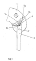
- FIG. 1 shows an eyeglass holder 1 made of horn material, in which an eyeglass temple 3, which can be pivoted about an axis of rotation 2, is held in the wearing position with the aid of magnetic forces.
- the temple 3 carries a magnetic element 4 on the oblique side 3a of its triangle-shaped tip 3b.
- the end face 1a of the temple holder 1 is angled in accordance with the oblique side 3a and forms a stop for the pivoting movement of the temple 3.
- a plate 5 made of magnetizable material is inserted flush into it, through which the magnetic opposite pole to the magnetic element 4 fastened to the temple 3 is formed.
- the forces prevailing between the plate 5 and the magnetic element 4 are sufficient to hold the temple 3 in the wearing position. They can be easily overcome by applying a small additional force to fold the temple 3.
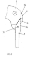
- FIG. 2 shows conventional glasses which have been retrofitted with the magnetic means according to the invention for holding the temple in the unfolded position.
- a first magnetic element 6 has been glued onto the outside 7a of a bracket holder 7.
- the magnetic element can also be screwed or riveted onto the bracket holder 7.
- a second magnetic element 8 is attached opposite to the first magnetic element 6 on the outside 9a of the temple 9.
- the magnetic element 8 can also be formed, for example, by a molded piece made of magnetizable material.
- the screw originally provided as the axis of rotation of the eyeglass temple 9 was replaced by a pin 10 which is held in a form-fitting manner in the temple holder, for example in the manner of a rivet.
- the pin can also be glued into the bracket holder.
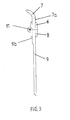
- FIG. 3 shows a further conventional pair of glasses with a joint 11 fastened to the inside 9b of the temple, which has been retrofitted with the magnetic means according to the invention for holding the temple in the unfolded position.
- a first magnetic element 6 has been glued to the outside 7a of a bracket holder 7 for this purpose.
- the magnetic element can also be screwed or riveted onto the bracket holder 7.
- a second magnetic element 8 is attached opposite to the first magnetic element 6 on the outside 9a of the temple 9.
- the magnetic element 8 can also be formed, for example, by a molded piece made of magnetizable material.
- the screw originally provided as the axis of rotation of the eyeglass temple 9 was replaced by a pin 10 which is held in a form-fitting manner in the temple holder, for example in the manner of a rivet.
- the pin can also be glued into the bracket holder.
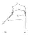
- the magnetic or magnetizable elements are designed as those when the hinged ends of the bracket and the bracket holder collide.
Landscapes
- Physics & Mathematics (AREA)
- Health & Medical Sciences (AREA)
- General Physics & Mathematics (AREA)
- Ophthalmology & Optometry (AREA)
- Optics & Photonics (AREA)
- Eyeglasses (AREA)
Description
- Die Erfindung betrifft ein Brillengestell, bei dem die Brillenbügel um eine Drehachse verschwenkbar in jeweils einem gabelförmigen Bügelhalter befestigt sind, wobei jeder Bügelhalter Mittel zum Halten der Brillenbügel in einer vorbestimmten Position aufweist.
- Der Tragekomfort von Brillen ist unter anderem davon abhängig, wie leicht es ist, die Brille aufzusetzen. Dieses Beurteilungskriterium ist besonders für solche Brillenträger wichtig, die gezwungen sind, ihre Brillen, beispielsweise zum Lesen, Autofahren und normalen Tagesgebrauch, häufig zu wechseln.
- Brillen werden in der Regel mit eingeklappten Brillenbügeln aufbewahrt. Daher besteht ein Problem beim Aufsetzen einer Brille darin, daß ihre Brillenbügel vor dem Aufsetzen auseinandergeklappt und in die für das Tragen der Brille angenehme Position geschwenkt werden müssen. Um das Auffinden der Trageposition zu erleichtern, werden die Brillenbügel oder Bügelhalterungen daher mit Anschlägen versehen, durch die die äußerste Schwenkposition der Brillenbügel festgelegt ist.
- Neben diesen Brillengestellen sind weitere Brillengestelle bekannt, bei denen die Brillenbügel oder die Bügelhalterungen selbst durch die Auswahl hochwertiger Materialien oder Zwischenschaltung von Federelementen so elastisch ausgelegt sind. Diese in der Herstellung aufwendigen und im Verkauf teuren Brillengestelle können eine Überdehnung des Brillenbügels über die Tragestellung hinaus aufnehmen, ohne daß die Gefahr des Brechens der Anschläge aufgrund einer übermäßigen Belastung entsteht. Ein gemeinsamer Nachteil der bekannten Brillengestelle besteht aber darin, daß die Brillenbügel, insbesondere beim einhändigen Auf- und Absetzen der Brille, selbsttätig aus der Trägerposition schwenken.
- Zur Lösung dieses Problems ist beispielsweise aus der US-Patentschrift 30 31 925 ein Brillengestell bekannt, bei dem in dem Überlappungsbereich zwischen jedem Brillenbügel und ihm zugeordnete Bügelhalter eine federnde Kugelrast zum Halten des Brillenbügels in einer vorbestimmten Position ausgebildet ist. Bei einer solchen Halterung rasten die Brillenbügel beim Auseinanderklappen in die vorbestimmte Trageposition ein und werden dort elastisch gehalten, bis sie zum Aufbewahren der Brille wieder eingelegt werden. Diese Art der Halterung erweist sich jedoch aufgrund der stärkeren Belastung von Halterung und Brillenbügel und des erforderlichen Bauraumes für die Rastelemente als ungeeignet für Brillengestelle, die aus sehr dünnem Material bestehen.
- Die Aufgabe der Erfindung besteht dagegen darin, mit einfachen Mitteln ein kostengünstiges Brillengestell mit hohem Tragekomfort zu schaffen, bei dem die Brillenbügel während des Auf- und Absetzens der Brille in der Trageposition gehalten werden, ohne daß es zu einer zusätzlichen Belastung der Brillenbügel kommt.
- Diese Aufgabe wird bei einem Brillengestell der eingangs genannten Art durch die Merkmale im kennzeichnenden Teil des Anspruchs 1 gelöst.
- Bei dieser Lösung werden die Brillenbügel mit Hilfe magnetischer Kräfte in der Trage- oder Aufbewahrungsposition gehalten. Auf diese Weise kann das Aufbringen von beispielsweise für das Einrasten der Kugel in die Einrastfläche erforderlichen Kräfte auf die Bügelhalterung vermieden werden. So ist diese Ausführung der Erfindung besonders für solche Brillengestelle geeignet, deren Bügelhalterung oder Brillenbügel aufgrund der Materialwahl oder der Abmessungen der Halterung zu schwach ausgelegt sind, um eine federnde Belastung aufzunehmen.
- Besteht das Brillengestell und besonders die Bügelhalterung selbst aus nicht magnetisierbarem Material, so kann ein magnetischer Halt der Brillenbügel auf einfache Weise dadurch verwirklicht werden, daß jeder Brillenbügel im Bereich der Bügelhalterung ein magnetisches Element trägt und in der Bügelhalterung eine den Gegenpol zu dem magnetischen Element bildende Platte aus magnetisierbarem Material eingesetzt ist, durch die die vorbestimmte Position festgelegt ist. Dabei kann eine einfache Ausführung der zweiten Lösungsalternative dadurch erzielt werden, daß die Bügelhalterungen aus magnetisierbarem Material bestehen und eine Anlagefläche aufweisen, an der das magnetische Element des Brillenbügels in der vorbestimmten Position anliegt.
- Das Nachrüsten von vorhandenen Brillengestellen mit magnetischen Haltemitteln kann besonders leicht dann ausgeführt werden, wenn eines der den magnetischen Pol und Gegenpol bildenden Mittel an der Außenseite der Brillenhalterung und das andere Mittel gegenüber zu dem ersten Mittel an der Außenseite des Brillenbügels befestigbar ist.
- Ein weiterer Vorteil der Erfindung besteht darin, daß die Drehachse durch einen formschlüssig in der Bügelhalterung gehaltenen Stift gebildet sein kann. Bei Verwendung eines solchen, beispielsweise nach Art einer Niete in der Bügelhalterung gehaltenen Stiftes besteht das Problem nicht mehr, daß Schrauben, die bei den bekannten Brillengestellen für die Drehachse verwendet werden, sich lösen und aus dem Brillengestell herausfallen. Dabei wird durch den magnetischen Halt der ausgeklappten Brillenbügel sichergestellt, daß die Brillenbügel trotz des nun nicht mehr vorhandenen Anpreßdruckes zwischen Bügelhalterung und Brillenbügel in der ausgeklappten Stellung gehalten werden.
- Im folgenden soll die Erfindung anhand einer ein Ausführungsbeispiel zeigenden Zeichnung näher erläutert werden. Es zeigen:
- Figur 1
- eine aufgebrochene Teilansicht eines Brillengestells mit ausgeschwenkten Brillenbügeln in Aufsicht,
- Figur 2
- eine Teilansicht einer anderen Ausführung der Erfindung in Aufsicht.
- Figur 3
- eine weitere Alternative der Erfindung in Aufsicht,
- Figur 4
- eine vierte Alternative der Erfindung in einer eingeschwenkten Stellung,
- Figur 5
- die Ausführungsalternative nach Figur 4 in ausgeschwenkter Stellung.
- Die Figur 1 zeigt eine Brillenhalterung 1 aus Hornmaterial, bei der ein um eine Drehachse 2 verschwenkbarer Brillenbügel 3 mit Hilfe magnetischer Kräfte in der Trageposition gehalten wird. Dazu trägt der Brillenbügel 3 an der schrägen Seite 3a seiner ein Dreieck bildenden Spitze 3b ein magnetisches Element 4. Die Stirnfläche 1a der Bügelhalterung 1 ist entsprechend der schrägen Seite 3a angewinkelt und bildet einen Anschlag für die Verschwenkbewegung des Brillenbügels 3. Gegenüberliegend zu dem magnetischen Element 4 ist in sie bündig eine Platte 5 aus magnetisierbarem Material eingesetzt, durch die der magnetische Gegenpol zu dem an dem Brillenbügel 3 befestigten magnetischen Element 4 gebildet ist. Die zwischen der Platte 5 und dem magnetischen Element 4 herrschenden Kräfte reichen aus, um den Brillenbügel 3 in der Trageposition zu halten. Sie können zum Zusammenlegen der Brillenbügel 3 leicht durch Aufbringen einer geringen Zusatzkraft überwunden werden.
- Figur 2 zeigt eine herkömmliche Brille, die mit den erfindungsgemäßen magnetischen Mitteln zum Halten der Brillenbügel in der ausgeklappten Stellung nachgerüstet worden ist. Ein erstes magnetisches Element 6 ist zu diesem Zweck auf die Außenseite 7a einer Bügelhalterung 7 aufgeklebt worden. Alternativ dazu kann das magnetische Element auch auf die Bügelhalterung 7 aufgeschraubt oder aufgenietet werden. In gleicher Weise ist ein zweites magnetisches Element 8 gegenüberliegend zu dem ersten magnetischen Element 6 an der Außenseite 9a des Brillenbügels 9 befestigt. Das magnetische Element 8 kann beispielsweise auch durch ein Formstück aus magnetisierbarem Material gebildet sein. Zusätzlich ist bei der Nachrüstung des Brillengestells die ursprünglich als Drehachse des Brillenbügels 9 vorgesehene Schraube durch einen Stift 10 ersetzt worden, der formschlüssig in der Bügelhalterung, beispielsweise nach Art einer Niete, gehalten ist. Alternativ dazu kann der Stift auch in die Bügelhalterung eingeklebt sein.
- Figur 3 zeigt eine weitere herkömmliche Brille mit einem an der Innenseite 9b des Brillenbügels befestigten Gelenk 11, die mit den erfindungsgemäßen magnetischen Mitteln zum Halten der Brillenbügel in der ausgeklappten Stellung nachgerüstet worden ist. Wie bei dem Ausführungsbeispiel nach Figur 2 ist ein erstes magnetisches Element 6 zu diesem Zweck auf die Außenseite 7a einer Bügelhalterung 7 aufgeklebt worden. Alternativ dazu kann das magnetische Element auch auf die Bügelhalterung 7 aufgeschraubt oder aufgenietet werden. In gleicher Weise ist ein zweites magnetisches Element 8 gegenüberliegend zu dem ersten magnetischen Element 6 an der Außenseite 9a des Brillenbügels 9 befestigt. Das magnetische Element 8 kann beispielsweise auch durch ein Formstück aus magnetisierbarem Material gebildet sein. Zusätzlich ist bei der Nachrüstung des Brillengestells die ursprünglich als Drehachse des Brillenbügels 9 vorgesehene Schraube durch einen Stift 10 ersetzt worden, der formschlüssig in der Bügelhalterung, beispielsweise nach Art einer Niete, gehalten ist. Alternativ kann der Stift auch in die Bügelhalterung eingeklebt sein.
- Bei dem Ausführungsbeispiel nach den Figuren 4 und 5 sind die magnetischen bzw. magnetisierbaren Elemente als die beim Aufklappen an einanderstoßenden Enden des Bügels und des Bügelhalters ausgebildet.
Claims (4)
- Brillengestell, bei dem die Brillenbügel (3) um eine Drehachse (2) verschwenkbar in jeweils einem gabelförmigen Bügelhalter (1) befestigt sind, wobei jeder Bügelhalter Mittel zum Halten eines Brillenbügels in einer vorbestimmten Schwenkposition aufweist,
dadurch gekennzeichnet, daß die Mittel zum Halten des brillenbügels entweder aus zwei magnetischen Elementen (4,5 ; 6,8) oder aus einem magnetisierbaren Element (5) und einem magnetischen Element (4) bestehen, die am vorderen Ende des Brillenbügels (3) bzw. an dem ihm zugeordneten Bügelhalter (1) so angeordnet sind, daß sie einen lösbaren magnetischen Halt für den Brillenbügel (3) in der vorbestimmten Schenkposition bilden. - Brillengestell nach Anspruch 2,
dadurch gekennzeichnet, daß die Bügelhalterungen (1) die magnetisierbaren Elemente darstellen und eine Anlagefläche (1a) aufweisen, an der das magnetische Element (4) des Brillenbügels (3) in der vorbestimmten Position anliegt. - Brillengestell nach Anspruch 1,
dadurch gekennzeichnet, daß eines der den magnetischen oder magnetisierbaren Elemente (6) an der Außenseite (7a) Brillenhalterung (7) und das andere Element (8) gegenüber zu dem ersten Element (7) an der Außenseite (9a) des Brillenbügels (9) befestigt ist. - Brillengestell nach einem der vorhergehenden Ansprüche,
dadurch gekennzeichnet, daß die Drehachse durch einen formschlüssig in der Bügelhalterung (7) gehaltenen Stift (10) gebildet ist.
Applications Claiming Priority (2)
| Application Number | Priority Date | Filing Date | Title |
|---|---|---|---|
| DE4122966 | 1991-07-11 | ||
| DE4122966A DE4122966C1 (de) | 1991-07-11 | 1991-07-11 |
Publications (2)
| Publication Number | Publication Date |
|---|---|
| EP0522594A1 EP0522594A1 (de) | 1993-01-13 |
| EP0522594B1 true EP0522594B1 (de) | 1994-08-10 |
Family
ID=6435911
Family Applications (1)
| Application Number | Title | Priority Date | Filing Date |
|---|---|---|---|
| EP92111863A Expired - Lifetime EP0522594B1 (de) | 1991-07-11 | 1992-07-11 | Brillengestell |
Country Status (3)
| Country | Link |
|---|---|
| EP (1) | EP0522594B1 (de) |
| AT (1) | ATE109903T1 (de) |
| DE (2) | DE4122966C1 (de) |
Cited By (1)
| Publication number | Priority date | Publication date | Assignee | Title |
|---|---|---|---|---|
| WO2014039521A1 (en) * | 2012-09-04 | 2014-03-13 | Armand Kidouchim | Eye wear hinge and process for assembly |
Families Citing this family (9)
| Publication number | Priority date | Publication date | Assignee | Title |
|---|---|---|---|---|
| DE4122966C1 (de) * | 1991-07-11 | 1992-06-04 | Heinz Juergen 4054 Nettetal De Sporket | |
| CH688667A5 (fr) * | 1993-06-09 | 1997-12-31 | Nationale Sa | Charnière pour lunettes. |
| DE19835197C1 (de) * | 1998-08-04 | 1999-11-18 | Menrad Ferdinand Gmbh Co Kg | Brillengestell |
| JP4789707B2 (ja) * | 2006-06-09 | 2011-10-12 | 株式会社和真 | メガネにおけるテンプルの付勢装置 |
| FR2950706B1 (fr) * | 2009-09-29 | 2011-11-11 | Logo | Lunettes a branches articulees elastiquement |
| FR2956751B1 (fr) * | 2010-02-22 | 2012-08-03 | Logo | Lunettes a branches magnetiques |
| JP2011185982A (ja) * | 2010-03-04 | 2011-09-22 | Kawamoto Kogaku Kogyo Kk | 眼鏡のヒンジ部 |
| EP2945006B1 (de) * | 2014-05-13 | 2017-07-05 | Hannes Gasser | Brille sowie Verfahren zur Herstellung einer Brille |
| FR3021125A1 (fr) | 2014-05-13 | 2015-11-20 | Intech Auvergne | Dispositif de jonction des branches sur le cadre d'une paire de lunettes |
Family Cites Families (9)
| Publication number | Priority date | Publication date | Assignee | Title |
|---|---|---|---|---|
| GB855976A (en) * | 1958-06-30 | 1960-12-14 | Newbold & Company Ltd | Improvements in spectacles |
| US3031925A (en) * | 1958-07-02 | 1962-05-01 | John W Barrington | Temple hinge for spectacle frames |
| US2986970A (en) * | 1958-10-13 | 1961-06-06 | Ruth Edwards Kilgour | Adjustable spectacles |
| FR1379630A (fr) * | 1963-04-18 | 1964-11-27 | Applic Matieres Plastiques | Lunettes perfectionnées |
| FR2262317B1 (de) * | 1974-02-27 | 1976-06-25 | Auge Bernard | |
| US4153347A (en) * | 1977-06-08 | 1979-05-08 | Myer C Randolph | Eyeglass frames with removable, interchangeable lenses, rims and temple pieces |
| IT8553881V0 (it) * | 1985-10-02 | 1985-10-02 | Lorenzo Poz Mario D I De | Cerniera per montature di occhiali |
| US4790645A (en) * | 1987-02-20 | 1988-12-13 | Gish Donald A | Fitted eyeglass frames |
| DE4122966C1 (de) * | 1991-07-11 | 1992-06-04 | Heinz Juergen 4054 Nettetal De Sporket |
-
1991
- 1991-07-11 DE DE4122966A patent/DE4122966C1/de not_active Expired - Lifetime
-
1992
- 1992-07-11 DE DE59200358T patent/DE59200358D1/de not_active Expired - Fee Related
- 1992-07-11 EP EP92111863A patent/EP0522594B1/de not_active Expired - Lifetime
- 1992-07-11 AT AT92111863T patent/ATE109903T1/de not_active IP Right Cessation
Cited By (1)
| Publication number | Priority date | Publication date | Assignee | Title |
|---|---|---|---|---|
| WO2014039521A1 (en) * | 2012-09-04 | 2014-03-13 | Armand Kidouchim | Eye wear hinge and process for assembly |
Also Published As
| Publication number | Publication date |
|---|---|
| DE59200358D1 (de) | 1994-09-15 |
| DE4122966C1 (de) | 1992-06-04 |
| EP0522594A1 (de) | 1993-01-13 |
| ATE109903T1 (de) | 1994-08-15 |
Similar Documents
| Publication | Publication Date | Title |
|---|---|---|
| DE69502077T2 (de) | Brillengestell | |
| DE69901017T2 (de) | Federscharnier für Brillen | |
| EP0522594B1 (de) | Brillengestell | |
| DE60100134T2 (de) | Umschlossener Brückenfedermechanismus für Sonnenbrillen mit Klemmbefestigung | |
| DE202007019108U1 (de) | Mechanisches Universalscharnier | |
| DE3785512T2 (de) | Linsenhalterung fuer brillen, insbesondere fuer rahmenlose brillen. | |
| EP0240790B1 (de) | Padsystem | |
| CH572222A5 (en) | Spectacles with two pairs of lenses - one pair fixed, other movable on hinges | |
| DE2744231A1 (de) | Federscharnier fuer eine brille | |
| DE8902196U1 (de) | Brillengestell | |
| EP1596242B1 (de) | Brille | |
| DE7935613U1 (de) | Scharnier zur verbindung zwischen brillenfassung und buegeln | |
| DE2923038A1 (de) | Brillengestell | |
| DE102020007383A1 (de) | Magnetischer Halt von Brillenbügeln. Gilt für Brillen aller Art und Sonnenbrillen | |
| DE29804368U1 (de) | Brille | |
| DE3005759A1 (de) | Nasenstuetzplaettchen-halter an einem brillengestell | |
| DE546413C (de) | Brille, deren Hauptgestell mit einem Zusatzgestell gleicher Groesse versehen ist | |
| DE375011C (de) | Wendebrille | |
| DE2060302A1 (de) | Brillengestell mit flexiblen Haltebuegeln | |
| DE202021004028U1 (de) | Brille, versehen mit einer abnehmbaren Verbindungsvorrichtung mit magnetischer Wirkung | |
| DE888321C (de) | Loses Vorsatzteil fuer Brillen | |
| DE3905197C2 (de) | ||
| DE3815620A1 (de) | Brille | |
| AT67719B (de) | Inversbrille. | |
| AT262079B (de) | Rückblickspiegel |
Legal Events
| Date | Code | Title | Description |
|---|---|---|---|
| PUAI | Public reference made under article 153(3) epc to a published international application that has entered the european phase |
Free format text: ORIGINAL CODE: 0009012 |
|
| AK | Designated contracting states |
Kind code of ref document: A1 Designated state(s): AT BE CH DE DK ES FR GB GR IT LI LU NL PT SE |
|
| 17P | Request for examination filed |
Effective date: 19921218 |
|
| 17Q | First examination report despatched |
Effective date: 19931213 |
|
| GRAA | (expected) grant |
Free format text: ORIGINAL CODE: 0009210 |
|
| AK | Designated contracting states |
Kind code of ref document: B1 Designated state(s): AT BE CH DE DK ES FR GB GR IT LI LU NL PT SE |
|
| PG25 | Lapsed in a contracting state [announced via postgrant information from national office to epo] |
Ref country code: IT Free format text: LAPSE BECAUSE OF FAILURE TO SUBMIT A TRANSLATION OF THE DESCRIPTION OR TO PAY THE FEE WITHIN THE PRE;WARNING: LAPSES OF ITALIAN PATENTS WITH EFFECTIVE DATE BEFORE 2007 MAY HAVE OCCURRED AT ANY TIME BEFORE 2007. THE CORRECT EFFECTIVE DATE MAY BE DIFFERENT FROM THE ONE RECORDED.SCRIBED TIME-LIMIT Effective date: 19940810 Ref country code: BE Effective date: 19940810 Ref country code: DK Effective date: 19940810 Ref country code: NL Effective date: 19940810 Ref country code: FR Effective date: 19940810 Ref country code: ES Free format text: THE PATENT HAS BEEN ANNULLED BY A DECISION OF A NATIONAL AUTHORITY Effective date: 19940810 Ref country code: GR Free format text: LAPSE BECAUSE OF FAILURE TO SUBMIT A TRANSLATION OF THE DESCRIPTION OR TO PAY THE FEE WITHIN THE PRESCRIBED TIME-LIMIT Effective date: 19940810 |
|
| REF | Corresponds to: |
Ref document number: 109903 Country of ref document: AT Date of ref document: 19940815 Kind code of ref document: T |
|
| REF | Corresponds to: |
Ref document number: 59200358 Country of ref document: DE Date of ref document: 19940915 |
|
| PG25 | Lapsed in a contracting state [announced via postgrant information from national office to epo] |
Ref country code: PT Effective date: 19941110 Ref country code: SE Effective date: 19941110 |
|
| EN | Fr: translation not filed | ||
| NLV1 | Nl: lapsed or annulled due to failure to fulfill the requirements of art. 29p and 29m of the patents act | ||
| GBT | Gb: translation of ep patent filed (gb section 77(6)(a)/1977) |
Effective date: 19950111 |
|
| PLBE | No opposition filed within time limit |
Free format text: ORIGINAL CODE: 0009261 |
|
| STAA | Information on the status of an ep patent application or granted ep patent |
Free format text: STATUS: NO OPPOSITION FILED WITHIN TIME LIMIT |
|
| NLXE | Nl: other communications concerning ep-patents (part 3 heading xe) |
Free format text: A REQUEST FOR RESTORATION TO THE PRIOR STATE HAS BEEN FILED ON 950501 |
|
| PG25 | Lapsed in a contracting state [announced via postgrant information from national office to epo] |
Ref country code: LU Free format text: LAPSE BECAUSE OF NON-PAYMENT OF DUE FEES Effective date: 19950731 |
|
| 26N | No opposition filed | ||
| PG25 | Lapsed in a contracting state [announced via postgrant information from national office to epo] |
Ref country code: DE Effective date: 19960402 |
|
| REG | Reference to a national code |
Ref country code: CH Ref legal event code: NV Representative=s name: A. BRAUN, BRAUN, HERITIER, ESCHMANN AG PATENTANWAE |
|
| PGFP | Annual fee paid to national office [announced via postgrant information from national office to epo] |
Ref country code: GB Payment date: 19960702 Year of fee payment: 5 |
|
| PGFP | Annual fee paid to national office [announced via postgrant information from national office to epo] |
Ref country code: AT Payment date: 19960829 Year of fee payment: 5 |
|
| PGFP | Annual fee paid to national office [announced via postgrant information from national office to epo] |
Ref country code: CH Payment date: 19961025 Year of fee payment: 5 |
|
| NLXE | Nl: other communications concerning ep-patents (part 3 heading xe) |
Free format text: THE REQUEST FOR RESTORATION TO THE PRIOR STATE AS PROVIDED FOR IN ART.17A OF THE PATENTS ACT IS REJECTED |
|
| PG25 | Lapsed in a contracting state [announced via postgrant information from national office to epo] |
Ref country code: AT Free format text: LAPSE BECAUSE OF NON-PAYMENT OF DUE FEES Effective date: 19970711 Ref country code: GB Free format text: LAPSE BECAUSE OF NON-PAYMENT OF DUE FEES Effective date: 19970711 |
|
| PG25 | Lapsed in a contracting state [announced via postgrant information from national office to epo] |
Ref country code: LI Free format text: LAPSE BECAUSE OF NON-PAYMENT OF DUE FEES Effective date: 19970731 Ref country code: CH Free format text: LAPSE BECAUSE OF NON-PAYMENT OF DUE FEES Effective date: 19970731 |
|
| GBPC | Gb: european patent ceased through non-payment of renewal fee |
Effective date: 19970711 |
|
| REG | Reference to a national code |
Ref country code: CH Ref legal event code: PL |