EP0504629B1 - Plattenförmiges Schallabsorberanlagenelement, sowie Schallabsorberanlage - Google Patents
Plattenförmiges Schallabsorberanlagenelement, sowie Schallabsorberanlage Download PDFInfo
- Publication number
- EP0504629B1 EP0504629B1 EP92103210A EP92103210A EP0504629B1 EP 0504629 B1 EP0504629 B1 EP 0504629B1 EP 92103210 A EP92103210 A EP 92103210A EP 92103210 A EP92103210 A EP 92103210A EP 0504629 B1 EP0504629 B1 EP 0504629B1
- Authority
- EP
- European Patent Office
- Prior art keywords
- grooves
- bores
- element according
- rows
- sound absorbing
- Prior art date
- Legal status (The legal status is an assumption and is not a legal conclusion. Google has not performed a legal analysis and makes no representation as to the accuracy of the status listed.)
- Expired - Lifetime
Links
- 230000001747 exhibiting effect Effects 0.000 claims 1
- 239000006096 absorbing agent Substances 0.000 abstract description 13
- 239000011093 chipboard Substances 0.000 description 3
- 239000011491 glass wool Substances 0.000 description 3
- 239000004575 stone Substances 0.000 description 3
- 239000002023 wood Substances 0.000 description 2
- 239000004568 cement Substances 0.000 description 1
- 230000006378 damage Effects 0.000 description 1
- ZINJLDJMHCUBIP-UHFFFAOYSA-N ethametsulfuron-methyl Chemical compound CCOC1=NC(NC)=NC(NC(=O)NS(=O)(=O)C=2C(=CC=CC=2)C(=O)OC)=N1 ZINJLDJMHCUBIP-UHFFFAOYSA-N 0.000 description 1
- 238000009413 insulation Methods 0.000 description 1
- 239000000463 material Substances 0.000 description 1
- 230000021715 photosynthesis, light harvesting Effects 0.000 description 1
- 239000011120 plywood Substances 0.000 description 1
- 239000011148 porous material Substances 0.000 description 1
- 239000007787 solid Substances 0.000 description 1
Images


Classifications
-
- G—PHYSICS
- G10—MUSICAL INSTRUMENTS; ACOUSTICS
- G10K—SOUND-PRODUCING DEVICES; METHODS OR DEVICES FOR PROTECTING AGAINST, OR FOR DAMPING, NOISE OR OTHER ACOUSTIC WAVES IN GENERAL; ACOUSTICS NOT OTHERWISE PROVIDED FOR
- G10K11/00—Methods or devices for transmitting, conducting or directing sound in general; Methods or devices for protecting against, or for damping, noise or other acoustic waves in general
- G10K11/16—Methods or devices for protecting against, or for damping, noise or other acoustic waves in general
- G10K11/172—Methods or devices for protecting against, or for damping, noise or other acoustic waves in general using resonance effects
Definitions
- the present invention relates to a plate-shaped sound absorber system element and a sound absorber system.
- Such plate-shaped sound absorber elements are known, which are perforated throughout.
- the prior art also includes chipboard with grooves from the visible side or with offset, continuous slots.
- Longitudinally and transversely grooved panels are also known, the front being longitudinally grooved and the rear of the panel being cross-grooved.
- There are also plates with a porous material structure. All of these known plate-shaped elements can only be changed within relatively narrow limits in such a way that they are suitable for a broad spectrum of acoustic problems, in particular for sound insulation.
- the present invention aims to provide a plate-shaped sound absorber system element, in which systems the respective execution of the elements can be selected depending on the task and the circumstances by changing the decisive parameters.
- Such a plate-shaped sound absorber element is characterized by one of the claims.
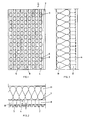
- the acoustic element 1 shown in FIGS. 1 to 3 points with its visible side into the room in which the sound source is located.
- grooves 4 are introduced in the longitudinal direction, which, as shown in FIG. 2, have a rectangular or square cross section with a groove base 5.
- the back of the plate-shaped acoustic element 1, the so-called absorber side 7, is provided with bores 8, the axes of which in the present case lie in the central planes of the grooves 4 and are perpendicular to the longitudinal axes of the grooves 4.
- the depth of the grooves 4 is approximately 1/3, as can be seen from FIG. 2 and is indicated there.
- leading passages 9 are formed, through which the energy to be damped passes from one side of the plate to the other.
- the absorber side 7 is covered with a stone or glass wool mattress 11, which serves as a destroyer for the energy, in the present case in particular sound energy.
- FIGS. 4 and 5 Another pattern of the procurement of the passages from the visible side of such an acoustic element, seen from the visible side, is shown in FIGS. 4 and 5 with a differently designed grid of the bores on the absorber side and different distances of the grooves on the visible side. Furthermore, the side areas to the groove bases 5 are connected to one another by rounded end faces 16, which in turn has a specific effect with regard to energy dissipation.
- the longitudinal grooves on the visible side 2 of the acoustic element have conical groove cross sections 18, while the bores 8 overlap in groups such that the passages 9 have corresponding longitudinal dimensions, a further possibility to deal with this Adapt the problem to be solved by changing the shape and location of the passageways.
- a side comb 12 on the one long side and a corresponding groove 13 on the other long side are additionally indicated, which allows these elements to be assembled into a more or less large area.
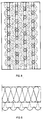
- Fig. 10 shows the front surface of an element. This is very pleasing in that the recessed transverse and longitudinal grooves form 20 and 21 squares. The bottom of the groove can be colored if necessary. Of course, it is also possible to provide the grooves so that standing or lying rectangles are created. this will depend on the spatial conditions.
- the absorber percentage can be changed from 0 to 25% of the area percentage.
- Sound-absorbing elements are installed sandwich-like, with an additional sound-absorbing plate, for example in the form of a chipboard or plasterboard, on the back of the element, i.e. is applied over the absorber mat (stone or glass wool mattress).
- an additional sound-absorbing plate for example in the form of a chipboard or plasterboard, on the back of the element, i.e. is applied over the absorber mat (stone or glass wool mattress).
- Such elements can also be used to control the sound energy, i.e. find use as so-called sound diffusers.
- such acoustic elements are preferably made from natural wood.
- the desired sound effect can be optimized accordingly by an optimal choice of solid wood.
- boards such as plywood, chipboard, MDF and.
- appropriate carrier plates with cement components for example "Duripanel”, can be used. Sound engineering solutions based on biological principles can also be realized by appropriate choice of materials.
- Such acoustic elements can be of large format, for example with lengths of up to 5 m and widths of 100 to 200 mm and thicknesses of 12 to 20 mm. This information is only for example.
- the visible side of the elements can with respect to groove depth, groove width, groove spacing, groove inclination and cross-section, u.
- the like variably designed and the surface profiling, e.g. smooth, rounded, concave, convex, etc. and adapted to the requirements at hand.
- the absorber side or back of the elements can be in terms of hole position, hole depth, e.g. conical holes, hole diameter and hole arrangement as well as hole shape, also meet these requirements.
- the combination of creasing or profiling on the visible side and perforations in the manner discussed on the back results in an optimal characteristic for solving the problem that arises.
- the surfaces of such elements can be varied as desired, i.e. with natural surfaces, lacquered, stained, glazed, opaque lacquered, painted etc.
Landscapes
- Physics & Mathematics (AREA)
- Engineering & Computer Science (AREA)
- Acoustics & Sound (AREA)
- Multimedia (AREA)
- Building Environments (AREA)
- Vehicle Interior And Exterior Ornaments, Soundproofing, And Insulation (AREA)
- Diaphragms For Electromechanical Transducers (AREA)
Description
- Die vorliegende Erfindung betrifft ein plattenförmiges Schallabsorberanlagen-element sowie eine Schallabsorberanlage.
- Es sind derartige plattenförmige Schallabsorberanlagen-elemente bekannt, welche durchgehend gelocht sind. Zum Stande der Technik gehören ferner Röhrenspanplatten mit Rillen von der Sichtseite her bzw. mit abgesetzten, durchgehenden Schlitzen. Auch sind längs- und quergerillte Platten bekannt, wobei die Frontseite längsgerillt, die Rückseite der Platte quergerillt ist. Es gibt ferner Platten mit porösen Materialaufbau. Alle diese bekannten plattenförmigen Elemente lassen sich nur in relativ engen Grenzen derart verändern, dass sie für ein breites Spektrum akustischer Probleme, insbesondere für den Schallschutz, geeignet sind.
- Die vorliegende Erfindung bezweckt die Schaffung eines plattenförmigen Schallabsorberanlagen-elementes, bei welchen anlagen durch Verändern der massgebendenParameterdie jeweilige Ausführung der Elemente aufgaben- und umständespezifisch wählbar ist.
- Ein derartiges plattenförmiges Schallabsorberanlagen-element zeichnet sich durch einen der Ansprüche aus.
- Die Erfindung wird anschliessend beispielsweise anhand einer Zeichnung erläutert.
- Es zeigen:
- Fig. 1 eine Aufsicht auf ein Akustikelement,
- Fig. 2 eine Vorderansicht des Akustikelementes gemäss Fig. 1 mit schallschluckender Stein- oder Glaswollmatratze,
- Fig. 3 eine Seitenansicht des Elementes nach den Fig. 1 und 2,
- Fig. 4 eine weitere Ausführung eines Akustikelementes analog Fig. 1,
- Fig. 5 eine Vorderansicht des Elementes nach Fig. 4 analog Fig. 2,
- Fig. 6 eine Variante eines Akustikelementes analog den Fig. 1 und 4,
- Fig. 7 eine Vorderansicht des Elementes gemäss Fig. 6,
- Fig. 8 eine Variante eines Akustikelelmentes analog den Fig. 1 und 4,
- Fig. 9 eine Vorderansicht des Elementes gemäss Fig. 6,
- Fig. 10 eine Vorderansicht eines Elementes analog Fig. 1 mit speziell ansprechenden Muster der Ausnehmungen auf der Sichtfläche.
- Das in den Fig. 1 bis 3 dargestellte Akustikelement 1 weist mit seiner Sichtseite in den Raum, in welchem sich die Schallquelle befindet. Auf dieser Sichtseite 2 sind in Längsrichtung Nuten 4 eingebracht, welche, wie Fig. 2 zeigt, rechteckigen oder quadratischen Querschnitt mit einem Nutengrund 5 haben.
- Die Rückseite des plattenförmigen Akustikelementes 1, die sog. Absorberseite 7, ist mit Bohrungen 8 versehen, deren Achsen im vorliegenden Falle in den Mittelebenen der Nuten 4 liegen und senkrecht auf den Längsachsen der Nuten 4 stehen. Es ist indessen auch möglich, die Achsen der Bohrungen 8 seitlich zu versetzen und/oder sie nicht senkrecht, sondern geneigt zur Längsachse der Nuten 4 zu bohren.
- Während die Bohrungen 8 eine Tiefe von ungefähr 2/3 der Plattendicke aufweisen, ist die Tiefe der Nuten 4 ungefähr 1/3, wie dies aus Fig. 2 ersichtlich und dort angedeutet ist. Im Bereich der Ueberdeckung der Nuten 4 und der Bohrungen 8 entstehen durch das Akustikelement 1 führende Durchgänge 9, durch welche die zu dämpfende Energie von der einen Plattenseite zur anderen gelangt.
- Die Absorberseite 7 ist, wie die Fig. 2 und 3 zeigen, mit einer Stein- oder Glaswollmatratze 11 bedeckt, welche als Vernichter für die Energie, im vorliegenden Fall insbesondere Schallenergie, dient.
- Ein anderes Muster der Beschaffung der Durchgänge von der Sichtseite eines derartigen Akustikelementes, von der Sichtseite aus gesehen, zeigen die Fig. 4 und 5 mit anders ausgebildetem Raster der Bohrungen auf der Absorberseite und unterschiedlichen Abständen der Rillen auf der Sichtseite. Ferner sind die Seitenbereiche zu den Nutengründen 5 durch gerundete Abschlussflächen 16 miteinander verbunden, was wiederum eine spezifische Wirkung bezüglich Energievernichtung zur Folge hat.
- In der Ausführung einer weiteren Variante gemäss den Fig. 6 und 7 weisen die Längsnuten auf der Sichtseite 2 des Akustikelementes konische Nutenquerschnitte 18 auf, während die Bohrungen 8 gruppenweise derart einander überschneiden, dass die Durchgänge 9 entsprechende Längsdimensionen aufweisen, eine weitere Möglichkeit, sich dem zu lösenden Problem durch Form- und Ortsänderung der Durchgänge anzupassen.
- In Fig. 7 sind zusätzlich ein seitlicher Kamm 12 auf der einen Längsseite und eine entsprechende Nut 13 auf der anderen Längsseite angedeutet, was erlaubt, diese Elemente zu einer mehr oder weniger grossen Fläche zusammenzubauen.
- Fig. 10 zeigt die Vorderfläche eines Elementes. Diese ist sehr gefällig, indem die ausgenommenen Quer-und Längsrillen 20 und 21 Quadrate bilden. Der Rillengrund kann gegebenenfalls gefärbt werden. Es ist natürlich auch möglich, die Rillen so vorzusehen, dass stehende oder liegende Rechtecke entstehen. Dies wird sich nach den Raumverhältnissen richten.
- Zusammenfassend ist folgendes festzuhalten:
- Durch Anbringen verschiedener Ausnehmungen, einerseits auf der Sichtseite und anderseits auf der Absorberseite solcher Elemente, und durch deren Variierbarkeit in besprochenem Sinne ist es möglich, die Charakteristiken bezüglich Schallvernichtung leicht zu verändern und damit den örtlichen Gegebenheiten und der Schallquelle anzupassen.
- Der Absorberanteil kann je nach Ausführung der Elemente von 0 bis 25% des Flächenanteils verändert werden.
- Schalldämmende Elemente werden sandchwichartig montiert, wobei zusätzlich eine schalldämmende Platte, beispielsweise in Form einer Spanplatte oder Gipsplatte, auf die Rückseite des Elementes, d.h. über der Absorbermatte (Stein- oder Glaswollmatratze), aufgebracht wird.
- Derartige Elemente können durch entsprechende Materialwahl und Formgebung der Ausnehmung auch zur Lenkung der Schallenergie, d.h. als sog. Schalldiffusoren, Verwendung finden.
- Es hat sich gezeigt, dass solche Akustikelemente vorzugsweise aus Naturhölzern angefertigt werden. Durch eine optimale Massivholzauswahl kann der gewünschte schalltechnische Effekt entsprechend optimiert werden. Es ist aber auch möglich, kombinierte Platten, wie Sperrholzplatten, Spanplatten, MDF-Platten u. dgl. zu verwenden. Gegebenenfalls, insbesondere bei brandgefährdeten Objekten, können entsprechende Trägerplatten mit Zementkomponenten, beispielsweise "Duripanel", Verwendung finden. Auch können durch entsprechende Materialwahl schalltechnische Lösungen auf biologischen Grundlagen realisiert werden.
- Derartige Akustikelemente können grossformatig ausgebildet sein, beispielsweise mit Längen bis zu 5m und Breiten von 100 bis 200 mm sowie Dicken von 12 bis 20 mm. Diese Angaben sind nur beispielsweise.
- Die Sichtseite der Elemente kann bezüglich Rillentiefe, Rillenbreite, Rillenabstand, Rillenneigung und - Querschnitt, u. dgl. variabel gestaltet sowie die Oberflächenprofilierung, z.B. glatt, gerundet, konkav, konvex, etc. sein und den vorliegenden Anforderungen angepasst werden. Die Absorberseite oder Rückseite der Elemente kann bezüglich Lochlage, Lochtiefe, z.B. konische Löcher, Lochdurchmesser und Lochanordnung sowie Lochform, ebenfalls diesen Anforderungen gerecht werden. Durch die Kombination von Rillung bzw. Profilierung auf der Sichtseite und Perforationen in der besprochenen Art auf der Rückseite ergibt sich jeweils eine optimale Charakteristik zur Lösung des auftretenden Problems.
- Die Oberflächen derartiger Elemente können je nach Wunsch variierbar sein, d.h. mit Naturoberflächen, lackiert, gebeizt, glasiert, deckend lackiert, gestrichen usw.
Claims (12)
Applications Claiming Priority (2)
| Application Number | Priority Date | Filing Date | Title |
|---|---|---|---|
| CH854/91A CH683112A5 (de) | 1991-03-20 | 1991-03-20 | Plattenförmiges Element, insbesondere für Schallabsorberanlagen, sowie Schallabsorberanlage. |
| CH854/91 | 1991-03-20 |
Publications (4)
| Publication Number | Publication Date |
|---|---|
| EP0504629A2 EP0504629A2 (de) | 1992-09-23 |
| EP0504629A3 EP0504629A3 (en) | 1993-06-16 |
| EP0504629B1 true EP0504629B1 (de) | 1995-02-01 |
| EP0504629B2 EP0504629B2 (de) | 1998-10-28 |
Family
ID=4196755
Family Applications (1)
| Application Number | Title | Priority Date | Filing Date |
|---|---|---|---|
| EP92103210A Expired - Lifetime EP0504629B2 (de) | 1991-03-20 | 1992-02-26 | Plattenförmiges Schallabsorberanlagenelement, sowie Schallabsorberanlage |
Country Status (5)
| Country | Link |
|---|---|
| US (1) | US5362931A (de) |
| EP (1) | EP0504629B2 (de) |
| AT (1) | ATE118111T1 (de) |
| CH (1) | CH683112A5 (de) |
| DE (1) | DE59201310D1 (de) |
Cited By (6)
| Publication number | Priority date | Publication date | Assignee | Title |
|---|---|---|---|---|
| US5422446A (en) * | 1991-03-20 | 1995-06-06 | Fries; Arthur | Panel shaped element, specifically for sound absorbing structures and a sound absorbing installation |
| US5532440A (en) * | 1993-12-10 | 1996-07-02 | Nitto Boseki Co., Ltd. | Light transmissive sound absorbing member |
| AU738186B3 (en) * | 2001-01-04 | 2001-09-13 | Wang Chao Hsiang | Sound absorbing panel |
| EP1138842A1 (de) | 2000-03-27 | 2001-10-04 | Mäger AG Innenausbau | Verfahren zur Herstellung eines schallabsorbierenden plattenförmigen Elementes und Vorrichtung zur Durchführung des Verfahrens |
| EP1508651A2 (de) | 2003-08-20 | 2005-02-23 | Diaplan Liegenschaftsverwaltungs GmbH | Akustikplatte mit Rillenstruktur |
| WO2006056351A1 (de) | 2004-11-24 | 2006-06-01 | Fritz Egger Gmbh & Co. | Deckschicht und paneel mit schallabsorbierenden eigenschaften sowie verfahren zu deren herstellung |
Families Citing this family (25)
| Publication number | Priority date | Publication date | Assignee | Title |
|---|---|---|---|---|
| EP0786759A4 (de) * | 1994-10-11 | 1999-12-22 | Nitto Boseki Co Ltd | Schalldämperkörper, schalldämferplatte und schalldämpfereinheit |
| AT406279B (de) * | 1998-01-20 | 2000-03-27 | Diaplan Liegenschaftsverwaltun | Akustikplattenelement |
| US20030006092A1 (en) * | 2001-06-27 | 2003-01-09 | Rpg Diffusor Systems, Inc. | Sound diffuser with low frequency sound absorption |
| DE10248072B4 (de) * | 2002-10-15 | 2006-08-24 | Waldemar Staudigel | Schallabsorberplatte |
| WO2005035906A1 (de) * | 2003-09-18 | 2005-04-21 | Peter Kellner | Beheizbares fussbodenelement mit oberflächenschicht |
| AT413121B (de) * | 2004-02-24 | 2005-11-15 | Lenz Nenning Gmbh | Schalldämmendes paneel |
| US7178630B1 (en) * | 2004-08-30 | 2007-02-20 | Jay Perdue | Acoustic device for wall mounting for diffusion and absorption of sound |
| US7497301B2 (en) * | 2005-01-27 | 2009-03-03 | Fleetguard, Inc. | Tubular acoustic silencer |
| US7604094B2 (en) * | 2005-04-14 | 2009-10-20 | Magyari Douglas P | Acoustic scatterer |
| KR100645824B1 (ko) * | 2005-06-14 | 2006-11-14 | 김영옥 | 흡음판넬 |
| WO2007032623A1 (en) * | 2005-09-15 | 2007-03-22 | Lg Chem, Ltd. | Heating floor system |
| WO2007125577A1 (ja) * | 2006-04-27 | 2007-11-08 | Masao Suzuki | 遮音装置 |
| US20080223653A1 (en) * | 2007-03-16 | 2008-09-18 | Seoul National University Industry Foundation | Poroelastic acoustical foam having enhanced sound-absorbing performance |
| US7721847B2 (en) * | 2007-03-27 | 2010-05-25 | 9 Wood, Inc. | Acoustic panel |
| DE102007040034B4 (de) | 2007-08-24 | 2010-02-11 | Vogl, Erich R. | Gipskartonlochplatte zur Schallabsorption |
| IT1393908B1 (it) * | 2009-05-13 | 2012-05-17 | Holteg S R L | Pannello fonoassorbente |
| WO2011047429A1 (en) * | 2009-10-21 | 2011-04-28 | Bellmax Acoustic Pty Ltd | Acoustic panel |
| US8424637B2 (en) * | 2010-01-08 | 2013-04-23 | Richard L. Lenz, Jr. | Systems and methods for providing an asymmetric cellular acoustic diffuser |
| ES2391336B1 (es) * | 2010-11-05 | 2013-10-02 | Alims 2000 S.L. | Panel acústico y cerramiento acústico. |
| EP2452792A1 (de) | 2010-11-15 | 2012-05-16 | Luigi Frati S.p.A. | Platte und Verfahren zur Herstellung von Platten |
| KR101184345B1 (ko) | 2012-07-03 | 2012-09-24 | 주식회사 케이에스알 | 음각흡음판 |
| US8573356B1 (en) * | 2013-03-07 | 2013-11-05 | Joab Jay Perdue | Adjustable device for acoustic modification |
| EP3259125A1 (de) * | 2015-02-18 | 2017-12-27 | Middle River Aircraft Systems | Schalldämpfende auskleidungen und verfahren zur formgebung eines einlasses einer schalldämpfenden auskleidung |
| US10657947B2 (en) * | 2017-08-10 | 2020-05-19 | Zin Technologies, Inc. | Integrated broadband acoustic attenuator |
| EP3880945A1 (de) | 2018-11-15 | 2021-09-22 | Cummins Power Generation IP, Inc. | Genset-gehäuse mit geringem akustischem rauschen |
Family Cites Families (14)
| Publication number | Priority date | Publication date | Assignee | Title |
|---|---|---|---|---|
| US1554179A (en) * | 1922-09-05 | 1925-09-15 | Dahlberg & Company | Sound-absorbing material for walls and ceilings |
| US1825770A (en) * | 1929-07-03 | 1931-10-06 | Arthur Sitzman | Sound absorbing construction |
| US2165101A (en) * | 1938-01-06 | 1939-07-04 | George E Hudson | Acoustic material |
| US2280631A (en) * | 1938-06-16 | 1942-04-21 | Burgess Battery Co | Facing sheet for sound absorbing material |
| GB946007A (en) * | 1960-12-23 | 1964-01-08 | Gomma Antivibranti Applic | Improvements relating to walls or ceilings having a sound absorbing covering |
| US3287869A (en) * | 1963-06-21 | 1966-11-29 | Featherston A Kilgore | Removable partition walls |
| US3269484A (en) * | 1963-09-24 | 1966-08-30 | Lighter Stephen | Acoustic absorbing structure |
| GB1398330A (en) * | 1972-07-31 | 1975-06-18 | Biritsh Broadcasting Corp | Acoustics of studios and the like |
| US3991848A (en) * | 1974-08-16 | 1976-11-16 | Frigitemp | Acoustical board |
| FR2462522A1 (fr) * | 1979-07-27 | 1981-02-13 | Scal Gp Condit Aluminium | Panneau d'isolation acoustique industrielle |
| US4556558A (en) * | 1982-05-13 | 1985-12-03 | Cedars-Sinai Medical Center | Treatment of factor VIII concentrate to minimize the affect of undesirable microorganisms |
| DE3233654C2 (de) * | 1982-09-10 | 1986-01-16 | Ewald Dörken AG, 5804 Herdecke | Schallabsorbierendes Bauelement |
| US4842097A (en) * | 1987-06-16 | 1989-06-27 | Woodward Bruce | Sound absorbing structure |
| DE4007556C2 (de) * | 1990-03-09 | 1998-05-07 | Gruenzweig & Hartmann Montage | Resonatorkulisse für Kulissenschalldämpfer |
-
1991
- 1991-03-20 CH CH854/91A patent/CH683112A5/de not_active IP Right Cessation
-
1992
- 1992-02-26 DE DE59201310T patent/DE59201310D1/de not_active Expired - Lifetime
- 1992-02-26 AT AT92103210T patent/ATE118111T1/de not_active IP Right Cessation
- 1992-02-26 EP EP92103210A patent/EP0504629B2/de not_active Expired - Lifetime
-
1994
- 1994-02-02 US US08/190,690 patent/US5362931A/en not_active Expired - Lifetime
Cited By (6)
| Publication number | Priority date | Publication date | Assignee | Title |
|---|---|---|---|---|
| US5422446A (en) * | 1991-03-20 | 1995-06-06 | Fries; Arthur | Panel shaped element, specifically for sound absorbing structures and a sound absorbing installation |
| US5532440A (en) * | 1993-12-10 | 1996-07-02 | Nitto Boseki Co., Ltd. | Light transmissive sound absorbing member |
| EP1138842A1 (de) | 2000-03-27 | 2001-10-04 | Mäger AG Innenausbau | Verfahren zur Herstellung eines schallabsorbierenden plattenförmigen Elementes und Vorrichtung zur Durchführung des Verfahrens |
| AU738186B3 (en) * | 2001-01-04 | 2001-09-13 | Wang Chao Hsiang | Sound absorbing panel |
| EP1508651A2 (de) | 2003-08-20 | 2005-02-23 | Diaplan Liegenschaftsverwaltungs GmbH | Akustikplatte mit Rillenstruktur |
| WO2006056351A1 (de) | 2004-11-24 | 2006-06-01 | Fritz Egger Gmbh & Co. | Deckschicht und paneel mit schallabsorbierenden eigenschaften sowie verfahren zu deren herstellung |
Also Published As
| Publication number | Publication date |
|---|---|
| US5362931A (en) | 1994-11-08 |
| EP0504629A3 (en) | 1993-06-16 |
| CH683112A5 (de) | 1994-01-14 |
| EP0504629A2 (de) | 1992-09-23 |
| DE59201310D1 (de) | 1995-03-16 |
| EP0504629B2 (de) | 1998-10-28 |
| ATE118111T1 (de) | 1995-02-15 |
Similar Documents
| Publication | Publication Date | Title |
|---|---|---|
| EP0504629B1 (de) | Plattenförmiges Schallabsorberanlagenelement, sowie Schallabsorberanlage | |
| DE19505025A1 (de) | Schallabsorbierendes Element, insbesondere plattenförmiges Element, sowie eine Schallabsorberanlage | |
| DE102013010091B4 (de) | Akustik-Element | |
| DE2616494B2 (de) | Sturz zum Überbrücken von öffnungen in Hohlwänden | |
| DE19806998A1 (de) | Holzplatte | |
| CH683855A5 (de) | Schallabsorptionsplatte. | |
| DE3241424C2 (de) | Verbindungseinrichtung | |
| DE10219981B4 (de) | Holzbautafel | |
| DE202004010276U1 (de) | Holzbautafel | |
| DE3305475C2 (de) | Akustikdeckenplatte aus einem Fasermaterial | |
| AT4807U1 (de) | Schallabsorbierendes paneel | |
| DE4343187C2 (de) | Dränplatte aus Kunststoffhartschaum | |
| DE29616050U1 (de) | Abdeckplatte für Decken- und Wandverkleidungen | |
| WO1983000054A1 (en) | Heat-insulating foam plate | |
| DE20210805U1 (de) | Isolierendes Bauelement | |
| DE202007018098U1 (de) | Unterlegematte | |
| DE20209926U1 (de) | Schallabsorbierende Platte und Möbelstück mit einer solchen Platte | |
| CH688777A5 (de) | Verkleidungsplatte fuer die Raumgestaltung sowie Verfahren zur Herstellung der Verkleidungsplatte. | |
| DE820637C (de) | Parkettplattenbelag | |
| DE9312416U1 (de) | Bauelement aus geblähten Stoffen | |
| DE102023104919A1 (de) | Modulares Akustikplattensystem und Akustikplatte | |
| DE2139967A1 (de) | Bauelement auf holzbasis fuer kleinere gebaeude | |
| DE2753467A1 (de) | Haengedeckensystem | |
| DE10015429C2 (de) | Wand- oder Deckenelement | |
| DE102011109924A1 (de) | Verkleidungselement |
Legal Events
| Date | Code | Title | Description |
|---|---|---|---|
| PUAI | Public reference made under article 153(3) epc to a published international application that has entered the european phase |
Free format text: ORIGINAL CODE: 0009012 |
|
| AK | Designated contracting states |
Kind code of ref document: A2 Designated state(s): AT BE CH DE DK ES FR GB GR IT LI LU NL SE |
|
| PUAL | Search report despatched |
Free format text: ORIGINAL CODE: 0009013 |
|
| AK | Designated contracting states |
Kind code of ref document: A3 Designated state(s): AT BE CH DE DK ES FR GB GR IT LI LU NL SE |
|
| 17P | Request for examination filed |
Effective date: 19930819 |
|
| 17Q | First examination report despatched |
Effective date: 19931229 |
|
| GRAA | (expected) grant |
Free format text: ORIGINAL CODE: 0009210 |
|
| AK | Designated contracting states |
Kind code of ref document: B1 Designated state(s): AT BE CH DE DK ES FR GB GR IT LI LU NL SE |
|
| PG25 | Lapsed in a contracting state [announced via postgrant information from national office to epo] |
Ref country code: IT Free format text: LAPSE BECAUSE OF FAILURE TO SUBMIT A TRANSLATION OF THE DESCRIPTION OR TO PAY THE FEE WITHIN THE PRE;WARNING: LAPSES OF ITALIAN PATENTS WITH EFFECTIVE DATE BEFORE 2007 MAY HAVE OCCURRED AT ANY TIME BEFORE 2007. THE CORRECT EFFECTIVE DATE MAY BE DIFFERENT FROM THE ONE RECORDED.SCRIBED TIME-LIMIT Effective date: 19950201 Ref country code: GB Effective date: 19950201 Ref country code: GR Free format text: LAPSE BECAUSE OF FAILURE TO SUBMIT A TRANSLATION OF THE DESCRIPTION OR TO PAY THE FEE WITHIN THE PRESCRIBED TIME-LIMIT Effective date: 19950201 Ref country code: NL Effective date: 19950201 Ref country code: FR Effective date: 19950201 Ref country code: DK Effective date: 19950201 Ref country code: ES Free format text: THE PATENT HAS BEEN ANNULLED BY A DECISION OF A NATIONAL AUTHORITY Effective date: 19950201 Ref country code: BE Effective date: 19950201 |
|
| REF | Corresponds to: |
Ref document number: 118111 Country of ref document: AT Date of ref document: 19950215 Kind code of ref document: T |
|
| PG25 | Lapsed in a contracting state [announced via postgrant information from national office to epo] |
Ref country code: AT Effective date: 19950226 |
|
| PG25 | Lapsed in a contracting state [announced via postgrant information from national office to epo] |
Ref country code: LU Free format text: LAPSE BECAUSE OF NON-PAYMENT OF DUE FEES Effective date: 19950228 |
|
| REF | Corresponds to: |
Ref document number: 59201310 Country of ref document: DE Date of ref document: 19950316 |
|
| PLBI | Opposition filed |
Free format text: ORIGINAL CODE: 0009260 |
|
| PG25 | Lapsed in a contracting state [announced via postgrant information from national office to epo] |
Ref country code: SE Effective date: 19950501 |
|
| 26 | Opposition filed |
Opponent name: LIGNOFORM BENKEN GMBH Effective date: 19950415 |
|
| EN | Fr: translation not filed | ||
| NLV1 | Nl: lapsed or annulled due to failure to fulfill the requirements of art. 29p and 29m of the patents act | ||
| GBV | Gb: ep patent (uk) treated as always having been void in accordance with gb section 77(7)/1977 [no translation filed] |
Effective date: 19950201 |
|
| PLBF | Reply of patent proprietor to notice(s) of opposition |
Free format text: ORIGINAL CODE: EPIDOS OBSO |
|
| PLBF | Reply of patent proprietor to notice(s) of opposition |
Free format text: ORIGINAL CODE: EPIDOS OBSO |
|
| PLAW | Interlocutory decision in opposition |
Free format text: ORIGINAL CODE: EPIDOS IDOP |
|
| PLAW | Interlocutory decision in opposition |
Free format text: ORIGINAL CODE: EPIDOS IDOP |
|
| REG | Reference to a national code |
Ref country code: CH Ref legal event code: NV Representative=s name: TROESCH SCHEIDEGGER WERNER AG |
|
| PUAH | Patent maintained in amended form |
Free format text: ORIGINAL CODE: 0009272 |
|
| STAA | Information on the status of an ep patent application or granted ep patent |
Free format text: STATUS: PATENT MAINTAINED AS AMENDED |
|
| 27A | Patent maintained in amended form |
Effective date: 19981028 |
|
| AK | Designated contracting states |
Kind code of ref document: B2 Designated state(s): AT BE CH DE DK ES FR GB GR IT LI LU NL SE |
|
| EN | Fr: translation not filed | ||
| PGFP | Annual fee paid to national office [announced via postgrant information from national office to epo] |
Ref country code: CH Payment date: 20100427 Year of fee payment: 19 |
|
| PGFP | Annual fee paid to national office [announced via postgrant information from national office to epo] |
Ref country code: DE Payment date: 20110223 Year of fee payment: 20 |
|
| REG | Reference to a national code |
Ref country code: CH Ref legal event code: PL |
|
| PG25 | Lapsed in a contracting state [announced via postgrant information from national office to epo] |
Ref country code: LI Free format text: LAPSE BECAUSE OF NON-PAYMENT OF DUE FEES Effective date: 20110228 Ref country code: CH Free format text: LAPSE BECAUSE OF NON-PAYMENT OF DUE FEES Effective date: 20110228 |
|
| REG | Reference to a national code |
Ref country code: DE Ref legal event code: R071 Ref document number: 59201310 Country of ref document: DE |
|
| REG | Reference to a national code |
Ref country code: DE Ref legal event code: R071 Ref document number: 59201310 Country of ref document: DE |
|
| PG25 | Lapsed in a contracting state [announced via postgrant information from national office to epo] |
Ref country code: DE Free format text: LAPSE BECAUSE OF EXPIRATION OF PROTECTION Effective date: 20120227 |