EP0487069A2 - Elektromagnetisches Relais - Google Patents
Elektromagnetisches Relais Download PDFInfo
- Publication number
- EP0487069A2 EP0487069A2 EP91119802A EP91119802A EP0487069A2 EP 0487069 A2 EP0487069 A2 EP 0487069A2 EP 91119802 A EP91119802 A EP 91119802A EP 91119802 A EP91119802 A EP 91119802A EP 0487069 A2 EP0487069 A2 EP 0487069A2
- Authority
- EP
- European Patent Office
- Prior art keywords
- coil
- movable
- block
- iron element
- electromagnetic relay
- Prior art date
- Legal status (The legal status is an assumption and is not a legal conclusion. Google has not performed a legal analysis and makes no representation as to the accuracy of the status listed.)
- Granted
Links
Images


Classifications
-
- H—ELECTRICITY
- H01—ELECTRIC ELEMENTS
- H01H—ELECTRIC SWITCHES; RELAYS; SELECTORS; EMERGENCY PROTECTIVE DEVICES
- H01H50/00—Details of electromagnetic relays
- H01H50/02—Bases; Casings; Covers
- H01H50/026—Details concerning isolation between driving and switching circuit
-
- H—ELECTRICITY
- H01—ELECTRIC ELEMENTS
- H01H—ELECTRIC SWITCHES; RELAYS; SELECTORS; EMERGENCY PROTECTIVE DEVICES
- H01H50/00—Details of electromagnetic relays
- H01H50/16—Magnetic circuit arrangements
- H01H50/18—Movable parts of magnetic circuits, e.g. armature
- H01H50/34—Means for adjusting limits of movement; Mechanical means for adjusting returning force
-
- H—ELECTRICITY
- H01—ELECTRIC ELEMENTS
- H01H—ELECTRIC SWITCHES; RELAYS; SELECTORS; EMERGENCY PROTECTIVE DEVICES
- H01H51/00—Electromagnetic relays
- H01H51/22—Polarised relays
- H01H51/2272—Polarised relays comprising rockable armature, rocking movement around central axis parallel to the main plane of the armature
- H01H51/2281—Contacts rigidly combined with armature
- H01H51/229—Blade-spring contacts alongside armature
-
- H—ELECTRICITY
- H01—ELECTRIC ELEMENTS
- H01H—ELECTRIC SWITCHES; RELAYS; SELECTORS; EMERGENCY PROTECTIVE DEVICES
- H01H50/00—Details of electromagnetic relays
- H01H50/44—Magnetic coils or windings
- H01H2050/446—Details of the insulating support of the coil, e.g. spool, bobbin, former
-
- H—ELECTRICITY
- H01—ELECTRIC ELEMENTS
- H01H—ELECTRIC SWITCHES; RELAYS; SELECTORS; EMERGENCY PROTECTIVE DEVICES
- H01H50/00—Details of electromagnetic relays
- H01H50/02—Bases; Casings; Covers
- H01H50/04—Mounting complete relay or separate parts of relay on a base or inside a case
- H01H50/041—Details concerning assembly of relays
- H01H50/042—Different parts are assembled by insertion without extra mounting facilities like screws, in an isolated mounting part, e.g. stack mounting on a coil-support
-
- H—ELECTRICITY
- H01—ELECTRIC ELEMENTS
- H01H—ELECTRIC SWITCHES; RELAYS; SELECTORS; EMERGENCY PROTECTIVE DEVICES
- H01H50/00—Details of electromagnetic relays
- H01H50/44—Magnetic coils or windings
- H01H50/443—Connections to coils
Definitions
- the present invention relates to an electromagnetic relay.
- FIG. 9 An example of a conventional electromagnetic relay is shown in Fig. 9.
- a coil block 5 is accommodated in a housing part 2 of a box-like base 1.
- a terminal 4 exposed from an upper surface of the base 1 is welded to a terminal 8 protruding at a hook part 7 formed at each end of a spool 6 of the coil block 5.
- a movable block 12 is attached to a permanent magnet 9 mounted at the center of the coil block 5 in a swaying fashion.
- a casing 17 is fitted into the base 1 after all the components of the electromagnetic relay are arranged as above.
- the electromagnetic relay in the aforementioned structure operates in the following manner. That is, when a voltage is impressed to a coil 10 of the coil block 5, the opposite ends of a movable iron element 13 of the movable block 12 are alternately attracted to the ends of a yoke 11 confronting thereto. As a consequence, a movable contact 15 at each end of a movable contact piece 14 which is supported by a supporting part 16 at either side of the movable iron element 13 is brought into contact with or detached from a fixed contact 3 exposed at an upper surface of the side wall of the base 1.
- the coil part has been coated in some cases with an insulative resin after the coil block 5 was assembled.
- this method takes a deal of cost and labor.
- the object of the present invention is therefore to provide an electromagnetic relay featuring a large dielectric strength between a coil and a contact at low cost.
- an electromagnetic relay which comprises a coil block including an iron core having a coil wound therearound via a spool, and a movable block supported in a manner to be able to turn either above or lower the coil block and having movable contact pieces integrally arranged with a movable iron element, so that the contacts are opened/closed by the movable contact pieces of the movable block when the movable block is turned in accordance with the magnetization or demagnetization of the coil block, wherein an insulative member is interposed between the coil block and the movable block.
- the spatial distance and surface distance between the coil and each contact can be elongated by the insulative member.
- an electromagnetic relay which comprises a coil block wherein a leg part of a coil terminal protruding from a brim of a spool having a coil wound therearound is extended downwards, a movable iron element driven in accordance with the magnetization or demagnetization of the coil block and, movable contact pieces driven and supported below the coil block along with the movable iron element thereby to open/close the contacts, characterized in that the central part of the leg part of the coil terminal in the vicinity of the movable iron element and movable contact piece is coated with an insulative resin.
- the rigidity of the leg part is eventually improved and moreover, the insulating property between the movable iron element or movable contact piece and the leg part of the coil terminal is enhanced.
- an electromagnetic relay which comprises a coil block including an iron core having a coil wound therearound via a spool, a movable block having movable contact pieces integrally arranged with a movable iron element and driven below the coil block, and an insulating plate provided at a leg part of a coil terminal integrally formed with a brim of the coil block and extending downwards, so that the contacts are opened/closed when an end of the movable iron element is brought into or out of contact with an end of the iron core in accordance with the magnetization or demagnetization of the coil, wherein a gauge insertion window is formed to measure the contact follow at a part of the insulating plate confronting the central part of the surface where the movable iron element butts against the iron core.
- An electromagnetic relay of the present invention generally consists of a first base block 20, a movable block 30, a second base block 40 as an insulative member, a coil block 50 and a casing 70.
- the first base block 20 is a generally rectangular plate-like body, having four pedestals 21 at respective four corners.
- a hook 22 extends from each pedestal 21 in a direction shown by an arrow A or A', and moreover, a grooved part 24 with a first guide 23 is formed at the side face of each pedestal 21.
- a protrusion 24a projects in the grooved part 24.
- a common terminal 25 is insertion-molded at the central part of an edge at each longer side of the first base block 20.
- the common terminal 25 has a welding part 26 projecting from the upper surface of the first base block 20.
- a generally T-shaped upper part of the welding part 26 is bent.
- a second guide part 28 projects at either nearby side of the welding part 26.
- 25 are provided a pair of projecting parts 29, 29 so as to prevent the deformation of a connecting part 34 when an up-and-down impact is impressed to the movable block 30 which will be described below.
- the movable contact pieces 32 of the movable block 30 are integrally molded at both lateral sides of a movable iron element 31 by a supporting part 33 made of resin.
- the movable iron element 31 is a generally I shape with a small width except for the opposite ends thereof.
- Each movable contact piece 32 is made of a conductive thin plate and bent along the side face of the movable iron element 31, having movable contacts 36 of a so-called twin structure at either end thereof.
- the aforementioned connecting part 34 in a generally T shape extends sideways from the central part of the movable contact pieces 32.
- a recess 35 is formed at the central part on the upper surface of the supporting part 33, so that the central part of the upper surface of the movable iron element 31 is exposed.
- the second base block 40 In order to form the second base block 40, four fixed contact pieces 43 are insertion-molded at respective four corners of a rectangular plate-like body 42 made of insulative resin.
- An elongated hole 41 is opened in the arrow direction B or B' at the central part of the second base block 40, and an engaging groove 49 is formed at the central part of each shorter side of the second base block 40.
- a pair of protruding parts 49a, 49a protrude in the arrow direction A or A' in each engaging groove 49.
- a leg 44 of the fixed contact piece 43 is projected downwards within an engaging recess 48 of a base part 47 at the lower surface of each corner of the plate-like body 42.
- a through-hole 45 is formed in the upper part of the leg 44.
- An end of the fixed contact piece 43 protrudes in the arrow direction A or A' from the end face of the shorter side of the plate-like body 42, on the lower surface of which is formed a fixed contact 46.
- one end of a generally U-shaped iron core 51 is bent outside and a permanent magnet 52 is brought to butt against the central part of the iron core 51.
- the iron core and permanent magnet are then formed into one body by a spool 53 made of insulative resin and wound with a coil 54 (referring to Fig. 2).
- a coil terminal 56 is insertion-molded at each of opposite upper ends of a brim 55 or 59 at the side edge of the spool 53.
- the brims 55 and 59 have stepped parts 55a and 59a, respectively.
- An upper end of the coil terminal 56 works as a tie part 57 for a coil leader which projects upwards from the brim 55 or 59.
- a side plate 65 made of an insulating material is insertion-molded in the middle of the confronting legs 58, 58 of the pair of the coil terminals 56, 56 simultaneously when the spool 53 is insertion-molded. Therefore, the legs 58, 58 are integrally coupled with each other.
- This side plate 65 has a window 66 for insertion of a thickness gauge.
- the window 66 is formed at such a position as to confront the central part of the surface where the movable iron element 31 butts against the iron core 51.
- the inner side faces of the insertion window 66 are able to guide the side edges of a thickness gauge to be inserted (not shown), so that the thickness gauge is positioned at the central part of the butting surface correctly.
- the thickness gauge is prevented from slipping out of the insertion window 66 even when the user lets his hold of the gauge because of the upper and lower inner faces of the insertion window 66.
- a wide section 67 spreads at the outer side end of each side plate 65, with engaging parts 67a, 67a formed at the root thereof.
- the adjacent coil terminals 56, 56 are integrally molded by the side plate 65 as is described hereinabove, the distance between the legs 58 and 58 can be set correctly and at the same time, the rigidity of the legs 58 can be increased. It is to be noted here that the leg 58 of the coil terminal 56 is extended in the arrow direction A or A' before the coil block 50 is mounted to the first base block 20, and bent as indicated in Fig. 1 when the block 50 is assembled with the first base block 20.
- the coil terminals 56 provided in the rim 59 are dummies without the coil 54 wound therearound.
- the casing 70 is in the form of a box, the lower face of which is opened.
- a gas vent 71 is formed at the central part of a shorter side on the upper surface of the casing 70.
- the magnetic relay is assembled into the above-described structure in a manner as will be depicted below.
- the connecting part 34 of the movable block 30 is brought to butt against the welding parts 26 of the common terminals 25 while being guided by the second guide parts 28, so that the movable block 30 is mounted to the first base block 20.
- the movable block 30 is rotatably supported at a fulcrum of the connecting part 34 when the connecting part 34 is welded to the welding parts 26.
- the second base block 40 is assembled with the first base block 20.
- each leg 44 of the fixed contact piece 43 is pressed into contact with the side face of the first base block 20 and accordingly the leg 44 is expanded wide and deformed in the arrow direction B or B'.
- the through-hole 45 of the leg 44 is fitted into the corresponding protrusion 24a of the first base block 20.
- the leg 44 is returned to the original shape.
- the second base block 40 is temporarily fixed to the first base block 20.
- the second base block 40 is positioned since each first guide 23 of the first base block 20 is fitted in a gap between the leg 44 and engaging recess 48 formed behind the leg 44.
- the protrusion 24a is thermally caulked afterwards. As a consequence, the second base block 40 is fixed to the first base block 20.
- the position of the connecting part 34 of the movable block 30 is regulated by the second guide parts 28 of the first base block 20, and also the position of the engaging recesses 48 of the second base block 40 is regulated by the first guides 23 of the first base block 20. Therefore, the positional relation between the movable contact 36 and fixed contact 46 can be set correctly.
- each leg 58 of the coil terminal 56 remains in the extended state in the direction of the arrow A or A' during the assembly.
- the stepped parts 55a, 59a of the brims 55, 59 of the spool 53 are fitted into the engaging grooves 49 of the second base block 40, whereby the spool 53 is positioned to the second base block 40. Then, the legs 58 are bent and the engaging parts 67a of each side plate 65 are engaged with the hooks 22 of the first base block 20. Thus, the coil block 50 is fixed to the first base block 20.
- the side faces of the permanent magnet 52 are guided by the recess 35 of the movable block 30 via the elongated hole 41 of the second base block 40, and the lower end face of the permanent magnet 52 butts against the movable iron element 31 of the movable block 30. Furthermore, the coil 54 is separated from the contacts 36, 46 by the flat plate 42 of the second base block 40 and brims 55, 59 of the coil block 50. Accordingly, sufficient insulation is secured in spite of a short straight distance between the coil 54 and contacts 36, 46.
- the contact follow will be measured with use of a non-magnetic thickness gauge inserted through the insertion window 66 of the side plate 65.
- the horizontal position of the thickness gauge is controlled by the insertion window 66. Specifically, since the side faces of the thickness gauge butt against the inner side faces of the insertion window 66, a front end of the thickness gauge is possible to correctly reach the central part of a free end of the movable iron element 31. Even if the user loses his hold of the gauge in this state, the thickness gauge is stopped by the upper and lower inner faces of the insertion window 66, thereby being prevented from falling off the side plate 65.
- each hook 22 of the first base block 20 is bent to be released from the engagement with the engaging part 67a of the side plate 65. And, the coil block 50 is detached and a horizontal end of each fixed contact piece 43 where the fixed contact 46 is formed is deflected for adjustment.
- the ceiling of the casing 70 is brought to butt against the upper surfaces of the brims 55, 59 of the spool 53 to be fitted with the first base block 20.
- the fitting part is sealed by a sealing material. After the internal gas is discharged through the gas vent 71, the assembled body is thermally sealed. The assembling process is thus completed.
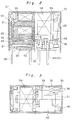
- the movable iron element 31 is turned, allowing the movable contacts 36 at the other side of the movable iron element 31 to close the confronting fixed contacts 46.
- the former contacts 36, 46 are consequently opened. If the magnetization is removed, the movable iron element 31 is returned to the original position.
- the fixed contacts 46 are arranged above the movable contacts 36 and moreover, the turning center of the movable iron element 31 is set above the movable contact pieces 32.
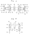
- Such an arrangement as according to the present invention is more advantageous in the following points in comparison with the case where fixed contacts 80 are provided below the movable contacts 36 as shown in Fig. 8.
- the movable contact piece 32 is slightly bent to obtain a predetermined contact pressure when the contacts are closed. Therefore, the movable contact piece 32 receives a force in a direction shown by an arrow at the welding time, with applying a moment in a direction shown by an arrow C to the movable iron element 31. Since this moment acts in a direction opposite to the direction in which the movable iron element 31 is separated from the iron core 51, the movable iron element 31 eventually becomes difficult to turn.
- the movable contact piece 32 is impressed with a force in a direction of an arrow, thereby causing a moment of a direction shown by an arrow D to the movable iron element 31.
- the moment is in the same direction as the turning direction of the movable iron element 31, whereby the contacts are easily separated from each other at the welding time.
- the electromagnetic relay is of a self-recovery type, wherein the magnetic balance is arranged to be lost by the shape of the iron core 51 of the coil block 50.
- the movable block 30 is turned below the coil block 50 in the foregoing embodiment, the movable block 30 may be turned above the coil block 50 and, in that case, the second base block 40 should be positioned above the coil block 50.
- the electromagnetic relay of the present invention since the coil is separated from each contact by the insulative member, it is possible to obtain a sufficient dielectric strength even though the straight distance between the coil and each contact is small.
- each leg of the coil terminal extending from the brim of the spool is coated with an insulative resin, the dielectric strength between the coil terminal and, movable iron element and movable contact piece is increased.
- the increase of the strength of the coil terminal owing to the insulative resin makes it easy to insert the coil terminal into the base block, and therefore the assembling efficiency is improved.
- the thickness gauge can be inserted with high positioning accuracy, thereby improving the reliability of the measured values.
Landscapes
- Physics & Mathematics (AREA)
- Electromagnetism (AREA)
- Electromagnets (AREA)
Applications Claiming Priority (6)
| Application Number | Priority Date | Filing Date | Title |
|---|---|---|---|
| JP31992290A JP2917507B2 (ja) | 1990-11-21 | 1990-11-21 | 電磁継電器 |
| JP2319923A JP2917508B2 (ja) | 1990-11-21 | 1990-11-21 | 電磁継電器 |
| JP319922/90 | 1990-11-21 | ||
| JP319923/90 | 1990-11-21 | ||
| JP12939890 | 1990-11-30 | ||
| JP129398/90U | 1990-11-30 |
Publications (3)
| Publication Number | Publication Date |
|---|---|
| EP0487069A2 true EP0487069A2 (de) | 1992-05-27 |
| EP0487069A3 EP0487069A3 (en) | 1993-01-27 |
| EP0487069B1 EP0487069B1 (de) | 1997-04-23 |
Family
ID=27315933
Family Applications (1)
| Application Number | Title | Priority Date | Filing Date |
|---|---|---|---|
| EP91119802A Expired - Lifetime EP0487069B1 (de) | 1990-11-21 | 1991-11-21 | Elektromagnetisches Relais |
Country Status (3)
| Country | Link |
|---|---|
| US (1) | US5270674A (de) |
| EP (1) | EP0487069B1 (de) |
| DE (1) | DE69125795T2 (de) |
Cited By (4)
| Publication number | Priority date | Publication date | Assignee | Title |
|---|---|---|---|---|
| GB2302989A (en) * | 1995-06-30 | 1997-02-05 | Copal Electronics | Electromagnetic relay |
| WO1998009311A1 (de) * | 1996-08-30 | 1998-03-05 | Siemens Aktiengesellschaft | Polarisiertes relais |
| CN102543584A (zh) * | 2010-12-21 | 2012-07-04 | 松下电器产业株式会社 | 电磁继电器 |
| EP2048684B1 (de) * | 2007-10-09 | 2015-03-18 | Siemens Aktiengesellschaft | Schaltgerät und Verfahren zum Einfügen bzw. Entfernen einer Toleranzeinlage in eine Magnetkammer eines Schaltgerätes |
Families Citing this family (7)
| Publication number | Priority date | Publication date | Assignee | Title |
|---|---|---|---|---|
| AU1672992A (en) * | 1991-04-22 | 1992-11-17 | Omron Corporation | Sealed electromagnetic relay |
| JPH07245052A (ja) * | 1994-03-04 | 1995-09-19 | Omron Corp | 電磁石装置 |
| DE19713659C1 (de) * | 1997-04-02 | 1998-06-25 | Siemens Ag | Elektromagnetisches Relais |
| JPH10334783A (ja) * | 1997-05-30 | 1998-12-18 | Takamisawa Denki Seisakusho:Kk | 電磁継電器および該電磁継電器の接点ばね組 |
| JP4742954B2 (ja) * | 2006-03-31 | 2011-08-10 | オムロン株式会社 | 電磁継電器 |
| JP6344282B2 (ja) * | 2015-03-26 | 2018-06-20 | オムロン株式会社 | コイル端子およびこれを備えた電磁継電器 |
| JP6787182B2 (ja) * | 2017-02-28 | 2020-11-18 | オムロン株式会社 | 電子機器のシール構造、シール構造を備えた電子機器、および、電子機器の製造方法 |
Citations (6)
| Publication number | Priority date | Publication date | Assignee | Title |
|---|---|---|---|---|
| EP0118715A1 (de) * | 1983-02-03 | 1984-09-19 | Siemens Aktiengesellschaft | Polarisiertes elektromagnetisches Relais |
| DE3802688A1 (de) * | 1988-01-29 | 1989-08-03 | Siemens Ag | Polarisiertes relais |
| JPH01274332A (ja) * | 1988-04-25 | 1989-11-02 | Omron Tateisi Electron Co | 電磁継電器 |
| JPH0233821A (ja) * | 1988-07-22 | 1990-02-05 | Omron Tateisi Electron Co | 電磁継電器 |
| EP0355817A2 (de) * | 1988-08-25 | 1990-02-28 | Omron Tateisi Electronics Co. | Elektromagnetisches Relais |
| EP0437209A2 (de) * | 1990-01-12 | 1991-07-17 | Omron Corporation | Elektromagnetisches Relais |
Family Cites Families (6)
| Publication number | Priority date | Publication date | Assignee | Title |
|---|---|---|---|---|
| DE802688C (de) * | 1949-05-08 | 1951-02-19 | Ernst Hahn | Vorrichtung zum Ein- und Ausbau von Ventilen, insbesondere bei Volkswagenmotoren |
| DE3002079A1 (de) * | 1980-01-21 | 1981-07-23 | Siemens AG, 1000 Berlin und 8000 München | Relais |
| US5126709A (en) * | 1987-03-13 | 1992-06-30 | Omron Tateisi Electronics Co. | Electromagnetic relay |
| US5015978A (en) * | 1987-05-29 | 1991-05-14 | Nec Corporation | Electromagnetic relay |
| CH677162A5 (de) * | 1989-10-30 | 1991-04-15 | Carlo Cavazzi Electromatic Ag | |
| JP2502989Y2 (ja) * | 1989-11-30 | 1996-06-26 | 自動車電機工業株式会社 | 電磁継電器 |
-
1991
- 1991-11-19 US US07/794,194 patent/US5270674A/en not_active Expired - Fee Related
- 1991-11-21 DE DE69125795T patent/DE69125795T2/de not_active Expired - Fee Related
- 1991-11-21 EP EP91119802A patent/EP0487069B1/de not_active Expired - Lifetime
Patent Citations (6)
| Publication number | Priority date | Publication date | Assignee | Title |
|---|---|---|---|---|
| EP0118715A1 (de) * | 1983-02-03 | 1984-09-19 | Siemens Aktiengesellschaft | Polarisiertes elektromagnetisches Relais |
| DE3802688A1 (de) * | 1988-01-29 | 1989-08-03 | Siemens Ag | Polarisiertes relais |
| JPH01274332A (ja) * | 1988-04-25 | 1989-11-02 | Omron Tateisi Electron Co | 電磁継電器 |
| JPH0233821A (ja) * | 1988-07-22 | 1990-02-05 | Omron Tateisi Electron Co | 電磁継電器 |
| EP0355817A2 (de) * | 1988-08-25 | 1990-02-28 | Omron Tateisi Electronics Co. | Elektromagnetisches Relais |
| EP0437209A2 (de) * | 1990-01-12 | 1991-07-17 | Omron Corporation | Elektromagnetisches Relais |
Non-Patent Citations (2)
| Title |
|---|
| PATENT ABSTRACTS OF JAPAN vol. 14, no. 41 (E-879)25 January 1990 & JP-A-01 274 332 ( OMRON TATEISI ELECTRON CO. ) 2 November 1989 * |
| PATENT ABSTRACTS OF JAPAN, Vol. 14, no. 182 (E-916)[4125], 12th April 1990; & JP-A-02 033 821 (OMRON TATEISI ELECTRONIC CORP.) 05-02-1990 * |
Cited By (4)
| Publication number | Priority date | Publication date | Assignee | Title |
|---|---|---|---|---|
| GB2302989A (en) * | 1995-06-30 | 1997-02-05 | Copal Electronics | Electromagnetic relay |
| WO1998009311A1 (de) * | 1996-08-30 | 1998-03-05 | Siemens Aktiengesellschaft | Polarisiertes relais |
| EP2048684B1 (de) * | 2007-10-09 | 2015-03-18 | Siemens Aktiengesellschaft | Schaltgerät und Verfahren zum Einfügen bzw. Entfernen einer Toleranzeinlage in eine Magnetkammer eines Schaltgerätes |
| CN102543584A (zh) * | 2010-12-21 | 2012-07-04 | 松下电器产业株式会社 | 电磁继电器 |
Also Published As
| Publication number | Publication date |
|---|---|
| EP0487069B1 (de) | 1997-04-23 |
| DE69125795T2 (de) | 1997-10-23 |
| US5270674A (en) | 1993-12-14 |
| EP0487069A3 (en) | 1993-01-27 |
| DE69125795D1 (de) | 1997-05-28 |
Similar Documents
| Publication | Publication Date | Title |
|---|---|---|
| US5270674A (en) | Electromagnetic relay | |
| EP0437209B1 (de) | Elektromagnetisches Relais | |
| US6879229B2 (en) | Electromagnetic relay | |
| JP3826464B2 (ja) | 電磁継電器 | |
| JPH086356Y2 (ja) | 電磁継電器 | |
| JP3109098B2 (ja) | 電磁継電器 | |
| JP2917508B2 (ja) | 電磁継電器 | |
| JP4000785B2 (ja) | リレー | |
| JP2562620Y2 (ja) | 電磁継電器 | |
| JP2519762Y2 (ja) | 電磁継電器 | |
| JP2917507B2 (ja) | 電磁継電器 | |
| JP3744094B2 (ja) | 高周波用開閉器 | |
| JP4089189B2 (ja) | 電磁継電器 | |
| JPS6331478Y2 (de) | ||
| JP2782226B2 (ja) | 電気機器 | |
| JP3707076B2 (ja) | 電磁継電器 | |
| JP2782634B2 (ja) | 電磁継電器 | |
| JP2000182496A (ja) | 電磁継電器及びその製造方法 | |
| JP2527781Y2 (ja) | 電磁継電器 | |
| JPH057712Y2 (de) | ||
| JP2533199B2 (ja) | 電磁継電器の製造方法 | |
| JPH10199387A (ja) | 電磁継電器 | |
| JP3938986B2 (ja) | 電磁継電器におけるヒンジばねと継鉄との結合構造 | |
| JP2533200B2 (ja) | 電磁継電器 | |
| JP4089188B2 (ja) | 電磁継電器 |
Legal Events
| Date | Code | Title | Description |
|---|---|---|---|
| PUAI | Public reference made under article 153(3) epc to a published international application that has entered the european phase |
Free format text: ORIGINAL CODE: 0009012 |
|
| 17P | Request for examination filed |
Effective date: 19911212 |
|
| AK | Designated contracting states |
Kind code of ref document: A2 Designated state(s): DE FR GB |
|
| PUAL | Search report despatched |
Free format text: ORIGINAL CODE: 0009013 |
|
| AK | Designated contracting states |
Kind code of ref document: A3 Designated state(s): DE FR GB |
|
| 17Q | First examination report despatched |
Effective date: 19940131 |
|
| GRAG | Despatch of communication of intention to grant |
Free format text: ORIGINAL CODE: EPIDOS AGRA |
|
| GRAH | Despatch of communication of intention to grant a patent |
Free format text: ORIGINAL CODE: EPIDOS IGRA |
|
| GRAH | Despatch of communication of intention to grant a patent |
Free format text: ORIGINAL CODE: EPIDOS IGRA |
|
| GRAA | (expected) grant |
Free format text: ORIGINAL CODE: 0009210 |
|
| AK | Designated contracting states |
Kind code of ref document: B1 Designated state(s): DE FR GB |
|
| REF | Corresponds to: |
Ref document number: 69125795 Country of ref document: DE Date of ref document: 19970528 |
|
| ET | Fr: translation filed | ||
| PLBE | No opposition filed within time limit |
Free format text: ORIGINAL CODE: 0009261 |
|
| STAA | Information on the status of an ep patent application or granted ep patent |
Free format text: STATUS: NO OPPOSITION FILED WITHIN TIME LIMIT |
|
| 26N | No opposition filed | ||
| PGFP | Annual fee paid to national office [announced via postgrant information from national office to epo] |
Ref country code: FR Payment date: 19981110 Year of fee payment: 8 |
|
| PGFP | Annual fee paid to national office [announced via postgrant information from national office to epo] |
Ref country code: GB Payment date: 19981127 Year of fee payment: 8 |
|
| PG25 | Lapsed in a contracting state [announced via postgrant information from national office to epo] |
Ref country code: GB Free format text: LAPSE BECAUSE OF NON-PAYMENT OF DUE FEES Effective date: 19991121 |
|
| GBPC | Gb: european patent ceased through non-payment of renewal fee |
Effective date: 19991121 |
|
| PG25 | Lapsed in a contracting state [announced via postgrant information from national office to epo] |
Ref country code: FR Free format text: LAPSE BECAUSE OF NON-PAYMENT OF DUE FEES Effective date: 20000731 |
|
| REG | Reference to a national code |
Ref country code: FR Ref legal event code: ST |
|
| PGFP | Annual fee paid to national office [announced via postgrant information from national office to epo] |
Ref country code: DE Payment date: 20011203 Year of fee payment: 11 |
|
| PG25 | Lapsed in a contracting state [announced via postgrant information from national office to epo] |
Ref country code: DE Free format text: LAPSE BECAUSE OF NON-PAYMENT OF DUE FEES Effective date: 20030603 |