EP0472893B1 - Blattransportvorrichtung und Tintenstrahlaufzeichnungsgerät mit dieser Vorrichtung - Google Patents
Blattransportvorrichtung und Tintenstrahlaufzeichnungsgerät mit dieser Vorrichtung Download PDFInfo
- Publication number
- EP0472893B1 EP0472893B1 EP91112132A EP91112132A EP0472893B1 EP 0472893 B1 EP0472893 B1 EP 0472893B1 EP 91112132 A EP91112132 A EP 91112132A EP 91112132 A EP91112132 A EP 91112132A EP 0472893 B1 EP0472893 B1 EP 0472893B1
- Authority
- EP
- European Patent Office
- Prior art keywords
- recording
- sheet
- ink
- spur
- recording apparatus
- Prior art date
- Legal status (The legal status is an assumption and is not a legal conclusion. Google has not performed a legal analysis and makes no representation as to the accuracy of the status listed.)
- Expired - Lifetime
Links
- 238000006243 chemical reaction Methods 0.000 claims description 10
- 238000009835 boiling Methods 0.000 claims description 4
- 230000000694 effects Effects 0.000 claims description 4
- 238000005452 bending Methods 0.000 claims 1
- 238000007599 discharging Methods 0.000 claims 1
- 239000000463 material Substances 0.000 description 14
- 238000010276 construction Methods 0.000 description 12
- 239000007788 liquid Substances 0.000 description 10
- 238000006073 displacement reaction Methods 0.000 description 8
- 238000011084 recovery Methods 0.000 description 5
- 239000003086 colorant Substances 0.000 description 3
- 230000008602 contraction Effects 0.000 description 2
- YCKRFDGAMUMZLT-UHFFFAOYSA-N Fluorine atom Chemical compound [F] YCKRFDGAMUMZLT-UHFFFAOYSA-N 0.000 description 1
- 229930182556 Polyacetal Natural products 0.000 description 1
- 230000005540 biological transmission Effects 0.000 description 1
- 238000004140 cleaning Methods 0.000 description 1
- 238000002474 experimental method Methods 0.000 description 1
- 229910052731 fluorine Inorganic materials 0.000 description 1
- 239000011737 fluorine Substances 0.000 description 1
- 238000010438 heat treatment Methods 0.000 description 1
- 230000010365 information processing Effects 0.000 description 1
- 238000012886 linear function Methods 0.000 description 1
- 239000007791 liquid phase Substances 0.000 description 1
- 239000002184 metal Substances 0.000 description 1
- 238000000034 method Methods 0.000 description 1
- 229920006324 polyoxymethylene Polymers 0.000 description 1
- 230000002940 repellent Effects 0.000 description 1
- 239000005871 repellent Substances 0.000 description 1
- 229920005989 resin Polymers 0.000 description 1
- 239000011347 resin Substances 0.000 description 1
- 230000004043 responsiveness Effects 0.000 description 1
- 230000000717 retained effect Effects 0.000 description 1
- XLYOFNOQVPJJNP-UHFFFAOYSA-N water Substances O XLYOFNOQVPJJNP-UHFFFAOYSA-N 0.000 description 1
Images


Classifications
-
- B—PERFORMING OPERATIONS; TRANSPORTING
- B41—PRINTING; LINING MACHINES; TYPEWRITERS; STAMPS
- B41J—TYPEWRITERS; SELECTIVE PRINTING MECHANISMS, i.e. MECHANISMS PRINTING OTHERWISE THAN FROM A FORME; CORRECTION OF TYPOGRAPHICAL ERRORS
- B41J13/00—Devices or arrangements of selective printing mechanisms, e.g. ink-jet printers or thermal printers, specially adapted for supporting or handling copy material in short lengths, e.g. sheets
- B41J13/02—Rollers
- B41J13/076—Construction of rollers; Bearings therefor
-
- B—PERFORMING OPERATIONS; TRANSPORTING
- B65—CONVEYING; PACKING; STORING; HANDLING THIN OR FILAMENTARY MATERIAL
- B65H—HANDLING THIN OR FILAMENTARY MATERIAL, e.g. SHEETS, WEBS, CABLES
- B65H2404/00—Parts for transporting or guiding the handled material
- B65H2404/10—Rollers
- B65H2404/14—Roller pairs
- B65H2404/141—Roller pairs with particular shape of cross profile
- B65H2404/1416—Roller pairs with particular shape of cross profile toothed or cylindrical
Definitions
- This invention relates to sheet conveying means according to the preamble of claim 1.
- the invention further relates to a recording apparatus comprising said sheet conveying means.
- generic sheet conveying means for conveying a sheet, which conveys the sheet with a roller brought into contact with the sheet with a pressure force.
- the shaft of a spur is provided by a resilient member to thereby obtain the pressure force against the sheet.
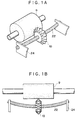
- Figure 1A is a perspective view showing an embodiment of the present invention.
- Figure 1B is a front view showing an embodiment of the present invention.
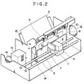
- Figure 2 is a schematic perspective view showing an ink jet recording apparatus to which an embodiment of the present invention is applied.
- Figure 3 is a graph showing the relation between the displacement and load of a spring in an embodiment of the present invention.
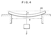
- Figure 4 illustrates a method of applying the load of Figure 3.
- FIGS 5A and 5B show another embodiment of the present invention.
- FIG. 2 schematically shows the construction of an ink jet printer to which the present invention is applied.
- a recording head 1 discharges ink by a recording signal, and is supplied with ink by an ink tank 2.
- a carriage 4 carrying thereon the recording head 1 and the ink head 2 is guided by guide shafts 3, and is reciprocally moved along the guide shafts 3 by a belt transmission mechanism and a driving motor, not shown.
- a recording sheet 5 is held from the back thereof by a platen 6 lying at a location opposed to the recording head 1. The recording sheet 5 is brought into intimate contact with the platen 6 by a paper keep plate 7.
- the recording sheet 5 thus brought into intimate contact with the platen is fed by a paper feeding roller 8.
- the recording paper 5 on which recording has been effected is discharged by a discharge roller 9.
- Spurs 10 are provided in opposed relationship with the discharge roller 9 and urge the recording sheet 5 against the discharge roller.
- the spurs 10 are biased toward the recording sheet 5 by an urging force by the flexure of a shaft which will be described later.
- the roller 8 and the roller 9 are driven by a paper feeding motor 12.
- a recovery system device 13 performs the recovery operation for preventing the clogging or the like of the discharge port of the recording head 1, and further performs the capping operation for preventing the desiccation of the discharge port when recording is not effected.
- This recovery system device 13 is driven by a recovery system driving motor 14.
- the recording sheet 5 is inserted along a paper pan 15.
- the operation of the above-described ink jet printer will now be described.
- the recording sheet 5 inserted along the paper pan 15 is fed to the platen 6 with the inserted leading end thereof turned into a U-shape by the roller 8 and is brought into intimate contract with the platen 6 by the keep plate 7.
- Ink is jetted from the recording head 1 by a recording signal and adheres to the recording sheet 5. By this adherence, characters or images are formed.
- the portions of the recording sheet 5 on which recording has been effected are successively fed upwardly by the roller 8.
- the recording sheet 5 When the leading end portion of the recording sheet 5 arrives at the spurs 10, the recording sheet 5 is pushed from its recording surface by the spurs 10 and the back of the recording sheet is urged against the roller 9, and the recording sheet is further conveyed upwardly by the rotation of the roller 9 and is discharged outwardly.
- each spur 10 having pointed tip ends is constructed as shown in Figures 1A and 1B.
- the reference numeral 10 designates the spur
- the reference numeral 22 denotes the shaft of the spur which comprises a closely wound tension coil spring
- the reference numeral 9 designates the discharge roller formed of rubber or the like
- the reference numeral 24 denotes spur holders for supporting the spur 10 and the shaft 22 of the spur.
- the graph of Figure 3 shows the relation between the flexure ⁇ of the center of the closely wound tension coil spring when as shown in Figure 4, a load is made to act vertically downwardly on the center of the spring supported at its opposite ends by a span l and said load.
- This equation (1) is the linear function of ⁇ and F within the limit of elasticity of the spring.
- this tension spring is used as the shaft of the spur of the sheet conveying means, this shaft flexes correspondingly to the thickness of the sheet being conveyed, and there is created the pressure force from the spur to the sheet which is found from equation (1).
- the pressure force varies greatly correspondingly to the thickness of the sheet being conveyed (as shown by (c) in Figure 3).
- the closely wound tension coil spring shown in (a) of Figure 3 which is used in the sheet conveying means according to the present invention is such that the pressure force created within the range of 0.5 mm to 2.0 mm of the displacement amount is about 17g to about 21g. Further, by varying the torsion applied to the coil when the coil is wound into a closely wound from, the initial tension F 0 can be changed to F 0 '.
- the closely wound tension coil spring shown in (b) of Figure 3 is such that the pressure force created within the range of 0.5 mm to 2.0 mm of the displacement amount can be changed from about 7 g to about 10 g.
- Figures 5A and 5B show another embodiment of the present invention.
- the material of the spring is a so-called spring material such as SUS or piano wire.
- the spur used is of a pillar-like shape having a diameter of 6 mm and a thickness of 2.2 mm and having pointed projections provided on the center of the direction of thickness over the side of the pillar.
- the material of the spur may be, for example, a metal if it is a water repellent material, but may suitably be fluorine resin, polyacetal or the like.
- the spur 30 is threaded through a shaft made of a closely wound tension coil spring, and is resilently mounted on the apparatus by means of members 25 and 25. At this time, the spur is provided so as to protrude toward the sheet conveying surface by 1 mm. That is, the spring is provided in a curved state on the apparatus while supporting the spur. The spur is restricted in its horizontal movement by the members 25 and 25.
- the displacement amount of the spring is 1.1 mm to 1.5 mm and the pressure force can keep a substantially constant value of about 9.5 g - 10.5 g. Therefore, where this spur is used in an ink jet recording apparatus, the pressure force obtained is substantially constant even if the thickness of the paper material varies, and stable conveyance of the paper material is possible.
- the wire material of the closely wound tension coil spring is thickened and the initial tension is increased to 50 g - 100 g, there can be provided sheet conveying means which will require a great pressure force for the conveyance of a paper material such as continuous paper.
- the spring constant of the closely wound tension coil spring which can be suitably used in the present embodiment is greater than 10 g /mm and less than 100 g/mm, and preferably greater than 30 g/mm and less than 50 g/mm, and most preferably greater than 40 g/mm and less than 45 g/mm.
- the outer diameter of the coil is greater than 0.5 mm and less than 2 mm, and preferably greater than 0.8 mm and less than 1.0 mm.
- the thickness of the wire material used is greater than 0.1 mm and less than 0.4 mm, and preferably greater than 0.15 mm and less than 0.2 mm.
- the span is determined by the wire diameter of the spring material used, the displacement amount and the pressure force obtained, and is preferably greater than 5 mm and less than 30 mm, and more preferably greater than 10 mm and less than 20 mm.
- the flexure amount (the displacement amount) ⁇ is greater than 1 mm and less than 2 mm, and preferably greater than 1 mm and less than 1.5 mm if the sheet material is plain paper, and preferably greater than 1 mm and less than 1.2 mm if the sheet material is continuous paper.
- the present invention brings about an excellent effect particularly in a recording head and a recording apparatus of the ink jet type which utilize heat energy to form flying droplets and accomplish recording, among the ink jet recording systems.
- the typical construction and principle of such system may preferably be based on the basic principle disclosed, for example, in U.S. Patent No. 4,723,129 or U.S. Patent No. 4,740,796.
- This system is applicable to both of the so-called on-demand type and the so-called continuous type, and particularly in the case of the on-demand type, it is effective because at least one driving signal corresponding to recording information and providing a rapid temperature rise exceeding nuclear boiling is applied to an electro-thermal conversion member disposed correspondingly to a sheet or a liquid path in which liquid (ink) is retained, whereby heat energy is generated in the electro-thermal conversion member to thereby cause film boiling on the heat-acting surface of a recording head with a result that a bubble in the liquid (ink) corresponding at one to one to said driving signal can be formed.
- the liquid (ink) is discharged through a discharge opening to thereby form at least one droplet. If this driving signal is made into a pulse-like shape, the growth and contraction of the bubble will take place appropriately on the spot and therefore, the discharge of the liquid (ink) particularly excellent in responsiveness can be achieved, and this is more preferable.
- the full line type recording head having a length corresponding to the width of the largest recording medium on which recording can be effected by a recording apparatus may be either of the construction as disclosed in the above-mentioned publications wherein the length of the head is satisfied by a combination of a plurality of recording heads and a construction as a unitarily formed single recording head, and the present invention can display the above-described effect more effectively.
- the present invention is effective when use is made of an interchangeable chip type recording head which can be electrically connected to the apparatus body or can be supplied with ink from the apparatus body by being mounted on the apparatus body, or a cartridge type recording head having an ink tank integrally provided in itself.
- recovery means for the recording head
- cleaning means for the recording head
- pressing or suction means for the recording head
- electro-thermal conversion member for the recording head
- heating element for the recording head
- preheating means for the recording head
- carrying out the preliminary discharge mode in which discharge discrete from that during recording is effected is also effective to accomplish stable recording.
- the recording mode of the recording apparatus is not limited to the recording mode for the main color such as black, but the recording head may be unitarily constructed or provided by a combination of a plurality of heads, and the present invention is also very effective for an apparatus provided with different colors or at least one of full colors by mixed colors.
- the ink has been described as liquid, but the ink may be ink which solidifies at room temperature or below and softens or is liquid at room temperature, or ink which assumes its liquid phase when the recording signal used is imparted, because it is usual with the above-described ink jet system that ink itself is temperature-controlled within the range of 30°C to 70°C so that the viscosity of the ink may be within a stable discharge range.
- the recording apparatus may adopt the form of an apparatus provided integrally with or discretely from an information processing instrument such as a word processor or a computer as the image output end thereof, or a copying apparatus combined with a reader, or a facsimile apparatus having the signal transmitting and receiving functions.
- an information processing instrument such as a word processor or a computer as the image output end thereof
- a copying apparatus combined with a reader
- a facsimile apparatus having the signal transmitting and receiving functions.
- sheet conveying means which creates a stable pressure force irrespective of the thickness of a sheet material being conveyed.
- an ink jet recording apparatus provided with sheet conveying means which can realize stable sheet conveyance by an appropriate pressure force against the presence of a portion to which an ink droplet does not yet adhere and the presence of the uneveness of the sheet material wet with ink.
Landscapes
- Ink Jet (AREA)
- Handling Of Cut Paper (AREA)
- Delivering By Means Of Belts And Rollers (AREA)
- Transmission Devices (AREA)
Claims (9)
- Blattransportvorrichtung zum Transportieren eines Blatts, die folgende Bauteile umfaßt:ein drehbares Element (9),einen Sporn (10), der in einer gegenüberliegenden Beziehung zu dem drehbaren Element (9) vorgesehen ist, undein elastisches Element (22) zum Stützen des Sporns (10), wobei sich das elastische Element (22) durchbiegt, wenn das Blattelement geführt wird, um den Sporn (10) zu dem drehbaren Element (9) zu drücken,dadurch gekennzeichnet, daßdas elastische Element (22) eine eng gewundene Schraubenfeder ist, wobei deren Rand durch einen Stützabschnitt (24) gestützt wird.
- Blattransportvorrichtung nach Anspruch 1,
dadurch gekennzeichnet, daßdas drehbare Element (9) eine Walze zum Transportieren des Blatts ist. - Blattransportvorrichtung nach Anspruch 1,
gekennzeichnet durchein Element (25) zum Begrenzen der Bewegung des Sporns (30) in einer axialen Richtung des elastischen Elements. - Aufzeichnungsgerät zum Bewirken einer Aufzeichnung auf einem Blatt, das eine Blattransportvorrichtung nach einem der Ansprüche 1 bis 3 und eine Aufzeichnungseinrichtung zum Bewirken der Aufzeichnung auf dem Blatt umfaßt.
- Aufzeichnungsgerät nach Anspruch 4, das ein Drucker ist.
- Aufzeichnungsgerät nach Anspruch 4,
dadurch gekennzeichnet, daßdie Aufzeichnungseinrichtung einen Aufzeichnungskopf hat, der mit einem elektrothermischen Umwandlungselement versehen ist, das in Übereinstimmung mit einem Aufzeichnungssignal Wärmeenergie erzeugt, und der die Wärmeenergie zum Ausstoßen von Tinte verwendet. - Aufzeichnungsgerät nach Anspruch 4,
dadurch gekennzeichnet, daßdie Aufzeichnungseinrichtung mit einem elektrothermischen Umwandlungselement versehen ist, das Wärmeenergie erzeugt, die ein Filmsieden in der Tinte verursacht. - Aufzeichnungsgerät nach Anspruch 4,
dadurch gekennzeichnet, daßdas Gerät ein Tintenstrahlaufzeichnungsgerät ist, das einen Aufzeichnungskopf mit einer Ausstoßöffnung zum Ausstoßen von Tinte durch diese, um dadurch eine Aufzeichnung auf einem Aufzeichnungsmittel zu bewirken, und einen Schlitten umfaßt, der in der Lage ist, den Aufzeichnungskopf in einer vorgegebenen Richtung zu bewegen. - Aufzeichnungsgerät nach Anspruch 8,
dadurch gekennzeichnet, daßder Aufzeichnungskopf ein elektrothermisches Umwandlungselement hat und die Tinte veranlaßt, durch das Wachsen einer Blase durch ein Filmsieden, das durch die durch das elektrothermische Umwandlungselement erzeugte Wärmeenergie verursacht wird, von der Ausstoßöffnung ausgestoßen zu werden.
Applications Claiming Priority (2)
| Application Number | Priority Date | Filing Date | Title |
|---|---|---|---|
| JP192673/90 | 1990-07-20 | ||
| JP2192673A JP2763387B2 (ja) | 1990-07-20 | 1990-07-20 | シート搬送装置及び該シート搬送装置を有するプリンタ |
Publications (2)
| Publication Number | Publication Date |
|---|---|
| EP0472893A1 EP0472893A1 (de) | 1992-03-04 |
| EP0472893B1 true EP0472893B1 (de) | 1997-04-23 |
Family
ID=16295141
Family Applications (1)
| Application Number | Title | Priority Date | Filing Date |
|---|---|---|---|
| EP91112132A Expired - Lifetime EP0472893B1 (de) | 1990-07-20 | 1991-07-19 | Blattransportvorrichtung und Tintenstrahlaufzeichnungsgerät mit dieser Vorrichtung |
Country Status (7)
| Country | Link |
|---|---|
| US (1) | US5606357A (de) |
| EP (1) | EP0472893B1 (de) |
| JP (1) | JP2763387B2 (de) |
| CN (1) | CN1052191C (de) |
| DE (1) | DE69125767T2 (de) |
| ES (1) | ES2102375T3 (de) |
| SG (1) | SG82542A1 (de) |
Families Citing this family (29)
| Publication number | Priority date | Publication date | Assignee | Title |
|---|---|---|---|---|
| GB2287433B (en) * | 1994-02-10 | 1996-09-04 | Seiko Epson Corp | Ink jet printer |
| AT401533B (de) * | 1994-06-28 | 1996-09-25 | Bergsmann Ludwig | Vorrichtung zum herstellen einer kabelverseilung mit wechselnder schlagrichtung |
| KR200150277Y1 (ko) * | 1996-02-24 | 1999-07-01 | 윤종용 | 프린터의 용지 배출 장치 |
| US5938191A (en) * | 1996-09-30 | 1999-08-17 | Xerox Corporation | Segmented drive roll for exit nip prior to exit trays |
| US6048060A (en) * | 1996-11-11 | 2000-04-11 | Toshiba Tec Kabushiki Kaisha | Printing medium discharge apparatus used in an ink jet printer |
| JP3372800B2 (ja) * | 1996-12-06 | 2003-02-04 | キヤノン株式会社 | 記録装置 |
| US6325560B1 (en) * | 1998-02-05 | 2001-12-04 | Canon Business Machines, Inc. | Wide format printer with detachable and replaceable paper feed unit components |
| JP3697076B2 (ja) * | 1998-08-27 | 2005-09-21 | キヤノン株式会社 | シート搬送装置及び記録装置 |
| DE69813831T2 (de) * | 1998-11-24 | 2004-02-26 | C.P.G. International S.P.A. | Rollenzuführgerät für ein Drucksubstrat mit nicht-einheitlicher Dicke |
| US6681045B1 (en) * | 1999-05-25 | 2004-01-20 | Silverbrook Research Pty Ltd | Method and system for note taking |
| JP2001139204A (ja) * | 1999-11-16 | 2001-05-22 | Matsushita Electric Ind Co Ltd | 画像形成装置におけるシート材の排出機構 |
| TW500669B (en) * | 2000-12-29 | 2002-09-01 | Benq Corp | Paper transporting device of printing machine |
| TW522098B (en) | 2001-04-09 | 2003-03-01 | Benq Corp | Recording media transporter and ink-jet printer using the recording media transporter |
| US6851801B2 (en) | 2001-08-29 | 2005-02-08 | Canon Kabushiki Kaisha | Recording material conveying device and ink jet recording apparatus using such device |
| JP4051559B2 (ja) * | 2003-03-26 | 2008-02-27 | ブラザー工業株式会社 | 搬送装置及びこの搬送装置を搭載した画像記録装置 |
| JP4243864B2 (ja) * | 2005-01-26 | 2009-03-25 | ブラザー工業株式会社 | 搬送装置及びそれを備えたインクジェット記録装置 |
| JP4534787B2 (ja) * | 2005-02-21 | 2010-09-01 | ブラザー工業株式会社 | 画像形成装置 |
| US7287922B2 (en) * | 2005-03-03 | 2007-10-30 | Lexmark International, Inc. | Exit roller system for an imaging apparatus including backup rollers configured to reduce tracking |
| CN100551710C (zh) * | 2006-07-27 | 2009-10-21 | 研能科技股份有限公司 | 送纸机构 |
| JP4743428B2 (ja) * | 2006-08-03 | 2011-08-10 | セイコーエプソン株式会社 | 記録装置 |
| US7955013B2 (en) * | 2006-10-27 | 2011-06-07 | Hewlett-Packard Development Company, L.P. | Media engaging members |
| TW200824911A (en) * | 2006-12-08 | 2008-06-16 | Benq Corp | Paper ejection mechanism having star wheels moveable with an inner door |
| JP2011062989A (ja) * | 2009-09-18 | 2011-03-31 | Fujifilm Corp | 記録装置 |
| CN102616005B (zh) * | 2012-03-13 | 2014-10-08 | 新会江裕信息产业有限公司 | 一种打印机上导纸器 |
| JP6197280B2 (ja) * | 2012-11-16 | 2017-09-20 | ブラザー工業株式会社 | 画像読取装置およびシート搬送装置 |
| JP5998961B2 (ja) * | 2013-01-31 | 2016-09-28 | ブラザー工業株式会社 | シート搬送装置 |
| JP5847856B2 (ja) * | 2014-01-14 | 2016-01-27 | キヤノン株式会社 | 搬送装置及び搬送装置を備えたプリント装置 |
| JP6874703B2 (ja) * | 2018-01-31 | 2021-05-19 | ブラザー工業株式会社 | シート搬送装置 |
| JP2024018271A (ja) * | 2022-07-29 | 2024-02-08 | 京セラドキュメントソリューションズ株式会社 | 媒体搬送装置および画像形成装置 |
Family Cites Families (31)
| Publication number | Priority date | Publication date | Assignee | Title |
|---|---|---|---|---|
| DE7712267U1 (de) * | Siemens Ag, 1000 Berlin Und 8000 Muenchen | |||
| CA1127227A (en) * | 1977-10-03 | 1982-07-06 | Ichiro Endo | Liquid jet recording process and apparatus therefor |
| US4330787A (en) * | 1978-10-31 | 1982-05-18 | Canon Kabushiki Kaisha | Liquid jet recording device |
| US4345262A (en) * | 1979-02-19 | 1982-08-17 | Canon Kabushiki Kaisha | Ink jet recording method |
| US4463359A (en) * | 1979-04-02 | 1984-07-31 | Canon Kabushiki Kaisha | Droplet generating method and apparatus thereof |
| US4313124A (en) * | 1979-05-18 | 1982-01-26 | Canon Kabushiki Kaisha | Liquid jet recording process and liquid jet recording head |
| US4279413A (en) * | 1979-10-17 | 1981-07-21 | Burroughs Corporation | Drive mechanisms for passbooks |
| JPS588679A (ja) * | 1981-07-08 | 1983-01-18 | Seiko Epson Corp | 紙送り機構 |
| US4558333A (en) * | 1981-07-09 | 1985-12-10 | Canon Kabushiki Kaisha | Liquid jet recording head |
| DE3207053A1 (de) * | 1982-02-26 | 1983-09-15 | Esselte Pendaflex Corp., 11530 Garden City, N.Y. | Etikettiergeraet |
| JPS59123670A (ja) * | 1982-12-28 | 1984-07-17 | Canon Inc | インクジエツトヘツド |
| JPS59138461A (ja) * | 1983-01-28 | 1984-08-08 | Canon Inc | 液体噴射記録装置 |
| US4478402A (en) * | 1983-02-07 | 1984-10-23 | Eastman Kodak Company | Nip drive for sheet feeding apparatus |
| JPS60116487A (ja) * | 1983-11-30 | 1985-06-22 | Nec Home Electronics Ltd | プリンタの紙送り装置 |
| JPS60143987A (ja) * | 1984-01-05 | 1985-07-30 | Citizen Watch Co Ltd | プリンタの紙送り機構 |
| JPH06102386B2 (ja) * | 1985-03-12 | 1994-12-14 | キヤノン株式会社 | インクジエツト記録装置 |
| US4767114A (en) * | 1985-07-30 | 1988-08-30 | Kabushiki Kaisha Toshiba | Sheet feeder |
| JPS6273978A (ja) * | 1985-09-26 | 1987-04-04 | Brother Ind Ltd | 印字装置 |
| JPH0521080Y2 (de) * | 1986-03-18 | 1993-05-31 | ||
| JPS634945U (de) * | 1986-06-27 | 1988-01-13 | ||
| JPS63278880A (ja) * | 1987-05-11 | 1988-11-16 | Nec Corp | プリンタの用紙送り装置 |
| JPS63302057A (ja) * | 1987-06-01 | 1988-12-08 | Seiko Epson Corp | バブルジエツトプリンタ |
| JPH0676155B2 (ja) * | 1987-06-10 | 1994-09-28 | 日本電気株式会社 | 用紙ジャム検出機構 |
| JPH01267076A (ja) * | 1988-04-20 | 1989-10-24 | Canon Inc | 記録装置 |
| JP2821747B2 (ja) * | 1988-08-01 | 1998-11-05 | キヤノン株式会社 | インクジェットプリンタ |
| JP2545362Y2 (ja) * | 1988-11-08 | 1997-08-25 | 沖電気工業株式会社 | 自動給紙装置 |
| JPH02158555A (ja) * | 1988-12-08 | 1990-06-19 | Canon Inc | 記録装置 |
| US5187497A (en) * | 1989-09-18 | 1993-02-16 | Canon Kabushiki Kaisha | Ink jet recording apparatus having gap adjustment between the recording head and recording medium |
| US5170184A (en) * | 1989-12-29 | 1992-12-08 | Canon Kabushiki Kaisha | Recording apparatus with improved recording medium conveying device |
| JPH04213546A (ja) * | 1990-06-05 | 1992-08-04 | Seiko Epson Corp | プリンタの記録媒体排出機構 |
| US5163674A (en) * | 1991-09-27 | 1992-11-17 | Xerox Corporation | Drive means for a recording medium having liquid images thereon |
-
1990
- 1990-07-20 JP JP2192673A patent/JP2763387B2/ja not_active Expired - Lifetime
-
1991
- 1991-07-19 ES ES91112132T patent/ES2102375T3/es not_active Expired - Lifetime
- 1991-07-19 DE DE69125767T patent/DE69125767T2/de not_active Expired - Lifetime
- 1991-07-19 EP EP91112132A patent/EP0472893B1/de not_active Expired - Lifetime
- 1991-07-19 SG SG9606791A patent/SG82542A1/en unknown
- 1991-07-20 CN CN91104890A patent/CN1052191C/zh not_active Expired - Fee Related
-
1995
- 1995-06-07 US US08/478,826 patent/US5606357A/en not_active Expired - Lifetime
Also Published As
| Publication number | Publication date |
|---|---|
| JP2763387B2 (ja) | 1998-06-11 |
| SG82542A1 (en) | 2001-08-21 |
| DE69125767T2 (de) | 1997-10-16 |
| CN1052191C (zh) | 2000-05-10 |
| ES2102375T3 (es) | 1997-08-01 |
| CN1058564A (zh) | 1992-02-12 |
| US5606357A (en) | 1997-02-25 |
| JPH0478555A (ja) | 1992-03-12 |
| DE69125767D1 (de) | 1997-05-28 |
| EP0472893A1 (de) | 1992-03-04 |
Similar Documents
| Publication | Publication Date | Title |
|---|---|---|
| EP0472893B1 (de) | Blattransportvorrichtung und Tintenstrahlaufzeichnungsgerät mit dieser Vorrichtung | |
| EP0729841B1 (de) | Medien-Förderung bei einem Tintenstrahldrucker | |
| EP0676296A1 (de) | Tintenstrahlaufzeichnungsgerät und Blatttransportvorrichtung dafür | |
| EP0630750B1 (de) | Aufzeichnungsgerät mit einer Abweichungseinstellvorrichtung | |
| JPH06115067A (ja) | インクジェット記録装置 | |
| JPH0490354A (ja) | インクジェット記録装置 | |
| EP0693381A1 (de) | Blätterbeförderungsvorrichtung | |
| EP0803371B1 (de) | Blattfördergerät | |
| US6113217A (en) | Ink-jet printing apparatus | |
| US5469197A (en) | Recording apparatus for controlling conveyance speed of recording medium in accordance with a type of recording data to be recorded | |
| US5504506A (en) | Information recording method capable of performing a high quality recording in accordance with printing conditions | |
| JPH05186086A (ja) | シート搬送装置及び前記シート搬送装置を用いた記録装置 | |
| JPH0679944A (ja) | 記録装置 | |
| JPH05104802A (ja) | シート給送装置及び前記シート給送装置を用いた記録装置 | |
| JPH0717088A (ja) | 記録装置 | |
| JPH0781047A (ja) | 記録装置および該記録装置を備えた情報処理システム | |
| JP2888459B2 (ja) | 記録装置 | |
| JP3157921B2 (ja) | インクジェット記録装置 | |
| JP3014832B2 (ja) | 記録装置 | |
| JPH07214845A (ja) | 記録装置 | |
| JPH08224939A (ja) | プリント装置 | |
| JPH08119486A (ja) | シート搬送装置及び記録装置 | |
| JPH0725097A (ja) | 記録装置 | |
| JPH0761071A (ja) | 記録媒体搬送機構及び記録装置 | |
| JPH05116793A (ja) | 記録装置 |
Legal Events
| Date | Code | Title | Description |
|---|---|---|---|
| PUAI | Public reference made under article 153(3) epc to a published international application that has entered the european phase |
Free format text: ORIGINAL CODE: 0009012 |
|
| AK | Designated contracting states |
Kind code of ref document: A1 Designated state(s): BE DE ES FR GB IT NL |
|
| 17P | Request for examination filed |
Effective date: 19920721 |
|
| 17Q | First examination report despatched |
Effective date: 19940217 |
|
| GRAH | Despatch of communication of intention to grant a patent |
Free format text: ORIGINAL CODE: EPIDOS IGRA |
|
| GRAH | Despatch of communication of intention to grant a patent |
Free format text: ORIGINAL CODE: EPIDOS IGRA |
|
| GRAA | (expected) grant |
Free format text: ORIGINAL CODE: 0009210 |
|
| AK | Designated contracting states |
Kind code of ref document: B1 Designated state(s): BE DE ES FR GB IT NL |
|
| REF | Corresponds to: |
Ref document number: 69125767 Country of ref document: DE Date of ref document: 19970528 |
|
| ET | Fr: translation filed | ||
| REG | Reference to a national code |
Ref country code: ES Ref legal event code: FG2A Ref document number: 2102375 Country of ref document: ES Kind code of ref document: T3 |
|
| PLBE | No opposition filed within time limit |
Free format text: ORIGINAL CODE: 0009261 |
|
| STAA | Information on the status of an ep patent application or granted ep patent |
Free format text: STATUS: NO OPPOSITION FILED WITHIN TIME LIMIT |
|
| 26N | No opposition filed | ||
| REG | Reference to a national code |
Ref country code: GB Ref legal event code: IF02 |
|
| PGFP | Annual fee paid to national office [announced via postgrant information from national office to epo] |
Ref country code: ES Payment date: 20100615 Year of fee payment: 20 |
|
| PGFP | Annual fee paid to national office [announced via postgrant information from national office to epo] |
Ref country code: BE Payment date: 20100626 Year of fee payment: 20 Ref country code: NL Payment date: 20100715 Year of fee payment: 20 |
|
| PGFP | Annual fee paid to national office [announced via postgrant information from national office to epo] |
Ref country code: IT Payment date: 20100719 Year of fee payment: 20 Ref country code: FR Payment date: 20100806 Year of fee payment: 20 Ref country code: DE Payment date: 20100731 Year of fee payment: 20 |
|
| PGFP | Annual fee paid to national office [announced via postgrant information from national office to epo] |
Ref country code: GB Payment date: 20100726 Year of fee payment: 20 |
|
| REG | Reference to a national code |
Ref country code: DE Ref legal event code: R071 Ref document number: 69125767 Country of ref document: DE |
|
| REG | Reference to a national code |
Ref country code: DE Ref legal event code: R071 Ref document number: 69125767 Country of ref document: DE |
|
| REG | Reference to a national code |
Ref country code: NL Ref legal event code: V4 Effective date: 20110719 |
|
| BE20 | Be: patent expired |
Owner name: *CANON K.K. Effective date: 20110719 |
|
| REG | Reference to a national code |
Ref country code: GB Ref legal event code: PE20 Expiry date: 20110718 |
|
| PG25 | Lapsed in a contracting state [announced via postgrant information from national office to epo] |
Ref country code: GB Free format text: LAPSE BECAUSE OF EXPIRATION OF PROTECTION Effective date: 20110718 |
|
| PG25 | Lapsed in a contracting state [announced via postgrant information from national office to epo] |
Ref country code: NL Free format text: LAPSE BECAUSE OF EXPIRATION OF PROTECTION Effective date: 20110719 |
|
| REG | Reference to a national code |
Ref country code: ES Ref legal event code: FD2A Effective date: 20120110 |
|
| PG25 | Lapsed in a contracting state [announced via postgrant information from national office to epo] |
Ref country code: ES Free format text: LAPSE BECAUSE OF EXPIRATION OF PROTECTION Effective date: 20110720 |
|
| PG25 | Lapsed in a contracting state [announced via postgrant information from national office to epo] |
Ref country code: DE Free format text: LAPSE BECAUSE OF EXPIRATION OF PROTECTION Effective date: 20110720 |