EP0803371B1 - Blattfördergerät - Google Patents
Blattfördergerät Download PDFInfo
- Publication number
- EP0803371B1 EP0803371B1 EP97106844A EP97106844A EP0803371B1 EP 0803371 B1 EP0803371 B1 EP 0803371B1 EP 97106844 A EP97106844 A EP 97106844A EP 97106844 A EP97106844 A EP 97106844A EP 0803371 B1 EP0803371 B1 EP 0803371B1
- Authority
- EP
- European Patent Office
- Prior art keywords
- sheet
- guide
- convey
- image forming
- forming apparatus
- Prior art date
- Legal status (The legal status is an assumption and is not a legal conclusion. Google has not performed a legal analysis and makes no representation as to the accuracy of the status listed.)
- Expired - Lifetime
Links
- 230000002093 peripheral effect Effects 0.000 claims description 17
- 238000007599 discharging Methods 0.000 claims description 4
- 230000015572 biosynthetic process Effects 0.000 description 2
- 238000010276 construction Methods 0.000 description 2
- 238000000034 method Methods 0.000 description 2
- 230000035939 shock Effects 0.000 description 2
- 230000001419 dependent effect Effects 0.000 description 1
- 238000011161 development Methods 0.000 description 1
- 230000018109 developmental process Effects 0.000 description 1
- 239000006185 dispersion Substances 0.000 description 1
- 238000004519 manufacturing process Methods 0.000 description 1
Images
Classifications
-
- B—PERFORMING OPERATIONS; TRANSPORTING
- B41—PRINTING; LINING MACHINES; TYPEWRITERS; STAMPS
- B41J—TYPEWRITERS; SELECTIVE PRINTING MECHANISMS, i.e. MECHANISMS PRINTING OTHERWISE THAN FROM A FORME; CORRECTION OF TYPOGRAPHICAL ERRORS
- B41J11/00—Devices or arrangements of selective printing mechanisms, e.g. ink-jet printers or thermal printers, for supporting or handling copy material in sheet or web form
- B41J11/0045—Guides for printing material
- B41J11/005—Guides in the printing zone, e.g. guides for preventing contact of conveyed sheets with printhead
-
- B—PERFORMING OPERATIONS; TRANSPORTING
- B41—PRINTING; LINING MACHINES; TYPEWRITERS; STAMPS
- B41J—TYPEWRITERS; SELECTIVE PRINTING MECHANISMS, i.e. MECHANISMS PRINTING OTHERWISE THAN FROM A FORME; CORRECTION OF TYPOGRAPHICAL ERRORS
- B41J13/00—Devices or arrangements of selective printing mechanisms, e.g. ink-jet printers or thermal printers, specially adapted for supporting or handling copy material in short lengths, e.g. sheets
- B41J13/0063—Handling thick cut sheets, e.g. greeting cards or postcards, larger than credit cards, e.g. using means for enabling or facilitating the conveyance of thick sheets
-
- B—PERFORMING OPERATIONS; TRANSPORTING
- B41—PRINTING; LINING MACHINES; TYPEWRITERS; STAMPS
- B41J—TYPEWRITERS; SELECTIVE PRINTING MECHANISMS, i.e. MECHANISMS PRINTING OTHERWISE THAN FROM A FORME; CORRECTION OF TYPOGRAPHICAL ERRORS
- B41J13/00—Devices or arrangements of selective printing mechanisms, e.g. ink-jet printers or thermal printers, specially adapted for supporting or handling copy material in short lengths, e.g. sheets
- B41J13/10—Sheet holders, retainers, movable guides, or stationary guides
- B41J13/14—Aprons or guides for the printing section
Definitions
- the present relates to an image forming apparatus comprising a sheet conveying device having an arcuate convey path.
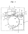
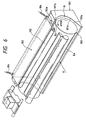
- Fig. 6 is a perspective view of a sheet conveying device of a generic image forming apparatus as disclosed in EP-A-0 737 589 (state of the art pursuant to Art. 54(3) EPC).
- the sheet conveying device has a so-called U-turn path for greatly changing a conveying direction of a sheet on which an image is to be formed.
- This sheet conveying device comprises a convey roller 100 rotated in a direction shown by the arrow R100, a convey guide 101 having an outer guide surface 101a facing to an outer peripheral surface 100a of the convey roller 100, and a pinch roller (convey sub-roller) 102 disposed downstream of the convey guide 101 in a rotating direction of the convey roller 100.
- a downstream outlet Gb of the U-turn path G is defined as a straight gap formed between the generatrix of the convey roller 100 and a terminal edge 101b of the outer guide surface 101a of the guide 101.
- the sheet fed to an inlet Ga of the U-turn guide G from a direction shown by the arrow A is conveyed through the U-turn path G by the convey roller 100 rotating in the direction R100.
- the tip end of the sheet reaches the pinch roller 102 while being guided by a lower surface of the pressure plate 103.
- the sheet is conveyed by the convey roller 100 and the pinch roller 102.
- a trail end of the sheet passes through the outlet Gb of the U-turn path G and then leaves through the pinch roller 102. Then, the sheet is conveyed to a downstream image forming portion.
- an image forming apparatus 105 includes a recording head 106 disposed immediately downstream of the pinch roller 102, since the sheet P is intermittently conveyed by the convey roller 100 by a predetermined amount and one-line recording is effected by the recording head 106, if the convey amount of the sheet P does not coincide with the recording width (in the conveying direction), a recording area will be deviated from a correct one, so that the desired image cannot be obtained.
- EP-A-514155 discloses a serial impact printer including an arcuate convey path formed between an outer cylindrical surface of a platen and a guide member having a guide surface curved along the outer cylindrical surface of the platen.
- the guide member moves with an impact dot head for guiding a printing sheet over the platen after the sheet passed the impact dot head.
- the guide member has two finger-shaped end portions guiding the front end of the printing sheet to a pair of downstream tension rollers.
- An object of the invention is to provide an image forming apparatus comprising a sheet conveying device including an arcuate convey path and an image forming portion disposed downstream of the sheet conveying device which can prevent dispersion of a convey amount of a sheet caused by a restoring force of the sheet generated when a trail end of the sheet is disengaged from a terminal edge of an outer guide surface.
- the image forming apparatus should have a simple construction without using additional means such as the above-mentioned braking means or flexible member.
- the terminal edge of the first guide (outer guide surface) is configured not to coincide with the straight line defined by the longitudinal axis of the convey roller, for example, even when a trail end of the sheet (such as a thick sheet) having great resiliency is disengaged from the terminal edge, the entire trail end of the sheet is not disengaged at once. Thus, the trail end of the sheet is gradually disengaged from the terminal edge, so that the restoring force can be weakened.
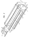
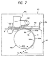
- a sheet conveying device shown in Figs. 1 and 2 comprises a convey roller 1, a guide member 2 and a convey sub-roller 5.
- the convey roller 1 having an outer peripheral surface 1a is rotatably supported by a frame (not shown) of the sheet conveying device and is rotated in a direction shown by the arrow R1 by a drive means (not shown).
- the guide member 2 is disposed to face to the convey roller 1 at the right side.
- the guide member 2 has an arc-shaped outer guide surface 2a facing to the outer peripheral surface 1a of the convey roller 1 and substantially coaxial with the outer peripheral surface 1a of the convey roller 1, so that a U-turn path G for conveying a sheet P is formed between the outer guide surface 2a and the outer peripheral surface 1a of the convey roller 1.
- the U-turn path G has a lower inlet Ga for the sheet P and an upper outlet Gb to change a conveying direction of the sheet from a direction shown by the arrow A to a direction shown by the arrow B.
- the outlet Gb is defined between a terminal edge 2A (disposed at a downstream end in the sheet conveying direction) of the outer guide surface 2a and the generatrix of the outer peripheral surface 1a opposed to the terminal edge.
- the terminal edge 2A is formed along the generatrix of the outer peripheral surface 1a (transverse to the sheet conveying direction), but is configured not to coincide with a straight line parallel to a longitudinal axis of the convey roller 1.
- the terminal edge 2A is tapered so that a central portion (in the axial direction) of the terminal edge is convex outwardly.
- a pinch sub-roller 3 urged against the outer peripheral surface 1a of the convey roller 1 is disposed within the U-turn path G.
- the convey sub-roller 5 is urged against the outer peripheral surface 1a of the convey roller 1 immediately at a downstream side of the outlet Gb of the U-turn path G in the sheet conveying direction and is rotatably mounted on a distal end 4b of a pressure plate (pressurizing member) 4.
- the pressure plate 4 can be rocked around a shaft 4a (parallel to the generatrix of the convey roller) and a proximal end 4c of the pressure plate is biased upwardly by tension springs 4d. With this arrangement, the convey sub-roller 5 mounted on the distal end 4b is urged against the outer peripheral surface of the convey roller 1 from the above with moderate pressure.
- a portion (left side portion) of a lower surface of the pressure plate 4 which faces to the outer peripheral surface 1a between the outlet Gb and the convey sub-roller 5 acts as an auxiliary guide surface for guiding the sheet P from the outlet Gb to the convey sub-roller 5.
- a portion (right side portion) of the lower surface of the pressure plate 4 which is contiguous to the downstream auxiliary guide surface acts as a second guide surface, and a straight path G1 for conveying the sheet P in a direction shown by the arrow B is defined between the second guide surface (and the auxiliary guide surface) and an upper surface of the guide member 2.
- An image forming portion is disposed downstream of the convey sub-roller 5, and includes a platen 6 for supporting a lower surface of the sheet P during the image formation, a recording head 9 for effecting the recording (for example, by discharging ink onto the sheet P), and a carriage 10 on which the recording head 9 is mounted and which is reciprocally shifted in a direction transverse to the sheet conveying direction.
- a discharge roller 7 and spur wheels 8 At a downstream side of the image forming portion, there are disposed a discharge roller 7 and spur wheels 8 for pinching and discharging the sheet P on which the image was recorded.
- thick sheet P conveyed from the direction A is pinched between the convey roller 1 and the pinch sub-roller 3 to be conveyed through the U-turn path G.
- the tip end of the sheet leaves the outlet Gb of the U-turn path G, the tip end of the sheet is guided by the pressure plate 4 and then is pinched by the convey sub-roller 5. Thereafter, the sheet P is further conveyed to pass through the platen 6.
- the tip end of the sheet is pinched between the discharge roller 7 and the spur wheels 8, the sheet is temporarily stopped.
- the recording is started. That is to say, first of all, one-line recording is performed by reciprocally shifting the recording head 9 by the carriage 10 while discharging the ink toward the surface of the sheet P, and then, the sheet P is conveyed by the convey roller 1 by a predetermined amount. One-line recording and the predetermined amount conveyance of the sheet are repeated until one-page recording is finished.
- the terminal edge 2A of the guide member 2 is configured not to coincide with a straight line but to be convex at the central portion, the trail end Pb of the sheet P is gradually disengaged from the terminal edge 2A from its both ends to its central portion. Accordingly, the conveying accuracy is maintained, thereby providing the good image. Further, since any additional braking means or an additional flexible sheet member is not required, the apparatus can be made cheaper and the operability can be improved.
- Fig. 3 is a perspective view showing a sheet conveying device in to a second embodiment of the present invention.
- a terminal edge 2B of the outer guide surface 2a is not curved to be convex outwardly (as is in the first embodiment), but is steppingly protruded outwardly (in the sheet conveying direction) from its both ends to its central portion as steps, as shown in Fig. 3.
- the trail end Pb of the sheet P is gradually disengaged from the terminal edge 2B from its both ends to its central portion, thereby achieving the same advantage as the first embodiment.
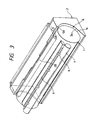
- Fig. 4 is a perspective view showing a sheet conveying device in a third embodiment of the present invention.
- a terminal edge 2C of the outer guide surface 2a is tapered to be concave inwardly at its central portion.
- the trail end Pb of the sheet P is gradually disengaged from the terminal edge 2C from its central portion to its both ends, thereby achieving the same advantage as those in the first and second embodiments.
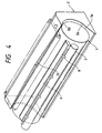
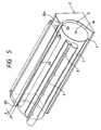
- Fig. 5 is a perspective view showing a sheet conveying device in a fourth embodiment of the present invention.
- a terminal edge 2D of the outer guide surface 2a is linearly tapered so that one end 2D1 of the terminal edge is protruded from the other end 2D2 in the sheet conveying direction by an amount of X.
- the trail end Pb of the sheet P is gradually disengaged from the terminal edge 2D from the left end (end 2D2) to the right end (end 2D1).
- substantially the same advantage as those in the first to third embodiments can be expected.
- the tapered amount X may be greater than 2 mm. The reason is that, even if the sheet is skew-fed more or less or the dimension of the sheet itself has slight error, the desired advantage can be obtained.
- the terminal edge 2A, 2B, 2C and 2D are tapered or stepped
- the terminal edge can be formed by combination of tapers or tapers and steps or may be curved to have an arcuate curvature. That is to say, the terminal edge is not limited to a special configuration, but may be appropriately configured so long as the trail end Pb of the sheet P can be gradually disengaged from the terminal edge.
- the configuration of the terminal edge may be determined by tests for providing the optimum advantage for various sheets having different size-and resiliency or may be selected on the basis of design and/or manufacturing limitations.
- the configuration of the terminal edge can be differentiated from the edge (generally, straight line) of the trail end of the sheet to be disengaged from the terminal edge so that the trail end of the sheet is gradually disengaged from the terminal end.
- the shock of the disengagement is reduced to prevent the conveying accuracy from being worsened.
- the image forming portion is disposed immediately at a downstream side of the U-turn path, the poor image due to the reduction in conveying accuracy can be avoided.
- the above-mentioned effective advantage can be obtained with a simple construction in which the terminal edge of the outer guide surface is merely altered and without using any additional braking means or additional flexible sheet member.
- the apparatus can be made cheaper and the operability can be improved.
- the configuration of the terminal edge from which the trail end of the sheet is gradually disengaged may be taper(s) of steps.
- the recording head used in the above-mentioned embodiments may be an ink jet head which includes heat generating elements disposed in nozzles and in which an ink droplet is discharged from the corresponding nozzle by growth of a bubble generated in the ink by thermal energy from the selected heat generating element.
Landscapes
- Feeding Of Articles By Means Other Than Belts Or Rollers (AREA)
- Delivering By Means Of Belts And Rollers (AREA)
- Registering Or Overturning Sheets (AREA)
- Registering, Tensioning, Guiding Webs, And Rollers Therefor (AREA)
Claims (9)
- Bilderzeugungsgerät zum Ausbilden eines Bildes auf einem Blatt unter Verwendung eines Aufzeichnungskopfes (9), wobei das Bilderzeugungsgerät aufweist:wobeieine Blattbeförderungsvorrichtung mit einem bogenförmigen Förderweg (G), ausgebildet zwischen einer äußeren Randfläche (1a) einer Förderrolle (1) zum Befördern des Blatts, und einer ersten Führung (2) mit einer Führungsfläche (2a), die entlang der äußeren Randfläche (1a) der Förderrolle (1) gebogen ist, um das Blatt entlang des bogenförmigen Förderweges (G) zu führen,und außerdem mit einer zweiten Führung (4), bereitgestellt stromabwärts von der ersten Führung (2) in einer Blattförderrichtung (B), um das durch die erste Führung durchgetretene Blatt zu führen; undeinem Bilderzeugungsabschnitt, bereitgestellt stromabwärts von der zweiten Führung (4), um das Bild unter Verwendung des Aufzeichnungskopfes (9) auf dem durch die zweite Führung geführten Blatt auszubilden,
die stromabwärtige Anschlußkante (2A; 2B; 2C; 2D) der ersten Führung (2) in der Blattförderrichtung (B) konfiguriert ist, nicht parallel zu einer durch die Längsachse der Förderrolle (1) definierten, geraden Linie zu sein. - Bilderzeugungsgerät gemäß Anspruch 1, wobei die Anschlußkante (2A; 2C) der ersten Führung (2) durch Abschrägungen ausgebildet ist, in ihrem Mittelabschnitt in der Blattförderrichtung (B) konvex oder konkav zu sein.
- Bilderzeugungsgerät gemäß Anspruch 1, wobei die Anschlußkante (2B) der ersten Führung (2) in Stufen ausgebildet ist, um in der Blattförderrichtung (B) von ihren beiden Enden zu ihrem Mittelabschnitt vorzuspringen.
- Bilderzeugungsgerät gemäß Anspruch 1, wobei die Anschlußkante (2D) der ersten Führung (2) linear abgeschrägt ist, so dass ein Ende davon in der Blattförderrichtung (B) vor das andere Ende vorspringt.
- Bilderzeugungsgerät gemäß jedem der vorangehenden Ansprüche, außerdem mit einem zweiten Förderweg (G1), der in der Lage ist, ein Blatt durch einen zwischen der Anschlußkante (2A) der ersten Führung (2) und der zweiten Führung (4) gebildeten Spalt einzubringen, so dass das Blatt durch die zweite Führung befördert wird, ohne durch die erste Führung durch zu treten.
- Bilderzeugungsgerät gemäß Anspruch 5, wobei die zweite Führung (4) sich zu der stromabwärtigen Seite hinter die Anschlußkante (2A) erstreckt, um dabei den zweiten Förderweg (G1) auszubilden.
- Bilderzeugungsgerät gemäß jedem der vorangehenden Ansprüche, außerdem mit einem Druckteil (4), um eine Nebenförderrolle (5) gegen die äußere Randfläche (1a) der Förderrolle (1) zu zwingen, wobei das Druckteil (4) eine zu der äußeren Randfläche gerichtete Führungsfläche zwischen dem Auslass (Gb) des bogenförmigen Förderweges (G) und der Nebenförderrolle (5) aufweist, um so die zweite Führung auszubilden.
- Bilderzeugungsgerät gemäß jedem vorangehenden Anspruch, wobei der Aufzeichnungskopf (9) ein Inkjetkopf ist, um durch das Abgeben von Tinte auf dem Blatt ein Bild auszubilden.
- Bilderzeugungsgerät gemäß Anspruch 8, wobei der Aufzeichnungskopf (9) das Bild unter Verwendung eines durch Wärmeenergie abgegebenen Tintentröpfchens bildet.
Applications Claiming Priority (3)
| Application Number | Priority Date | Filing Date | Title |
|---|---|---|---|
| JP10589696A JP3290886B2 (ja) | 1996-04-25 | 1996-04-25 | シート材搬送装置 |
| JP10589696 | 1996-04-25 | ||
| JP105896/96 | 1996-04-25 |
Publications (3)
| Publication Number | Publication Date |
|---|---|
| EP0803371A2 EP0803371A2 (de) | 1997-10-29 |
| EP0803371A3 EP0803371A3 (de) | 1998-08-26 |
| EP0803371B1 true EP0803371B1 (de) | 2003-10-22 |
Family
ID=14419669
Family Applications (1)
| Application Number | Title | Priority Date | Filing Date |
|---|---|---|---|
| EP97106844A Expired - Lifetime EP0803371B1 (de) | 1996-04-25 | 1997-04-24 | Blattfördergerät |
Country Status (4)
| Country | Link |
|---|---|
| US (1) | US5913511A (de) |
| EP (1) | EP0803371B1 (de) |
| JP (1) | JP3290886B2 (de) |
| DE (1) | DE69725641T2 (de) |
Families Citing this family (11)
| Publication number | Priority date | Publication date | Assignee | Title |
|---|---|---|---|---|
| US6170820B1 (en) * | 1997-09-12 | 2001-01-09 | Unisys Corporation | Roller biasing for sheet engagement |
| US20040164486A1 (en) * | 2003-02-26 | 2004-08-26 | Chuan-Yu Hsu | Document sheet conveying apparatus |
| JP4555253B2 (ja) * | 2006-05-10 | 2010-09-29 | 株式会社リコー | 用紙搬送装置および画像形成装置 |
| JP2008110529A (ja) * | 2006-10-30 | 2008-05-15 | Sony Corp | 搬送装置及び画像形成装置 |
| US7594657B2 (en) * | 2007-01-31 | 2009-09-29 | Hewlett-Packard Development Company, L.P. | Medium pressing guide |
| KR101428481B1 (ko) * | 2007-08-17 | 2014-08-11 | 삼성전자 주식회사 | 인쇄매체이송장치 및 이를 구비하는 화상형성장치 |
| JP4702417B2 (ja) * | 2008-08-29 | 2011-06-15 | ブラザー工業株式会社 | 記録シート搬送装置 |
| JP2012082058A (ja) * | 2010-10-13 | 2012-04-26 | Seiko Epson Corp | 搬送装置、及び、搬送方法 |
| JP5750418B2 (ja) * | 2012-09-20 | 2015-07-22 | 京セラドキュメントソリューションズ株式会社 | シート搬送装置及びこれを備えた画像形成装置 |
| CN103552862A (zh) * | 2013-11-19 | 2014-02-05 | 赵士立 | 一种模切机的给纸器 |
| US12384176B2 (en) | 2020-09-30 | 2025-08-12 | Hewlett-Packard Development Company, L.P. | Sheet inlet and outlet |
Family Cites Families (5)
| Publication number | Priority date | Publication date | Assignee | Title |
|---|---|---|---|---|
| JPH07106798B2 (ja) * | 1988-11-30 | 1995-11-15 | 三田工業株式会社 | 給送装置 |
| EP0514155B1 (de) * | 1991-05-15 | 1995-08-09 | Seiko Epson Corporation | Serieller Anschlagdrucker |
| KR970000610B1 (ko) * | 1992-06-04 | 1997-01-16 | 가부시키가이샤 테크 | 프린터의 용지배출장치 |
| JP3093560B2 (ja) * | 1993-05-10 | 2000-10-03 | キヤノン株式会社 | 画像形成装置 |
| JP3584085B2 (ja) * | 1995-06-09 | 2004-11-04 | セイコーエプソン株式会社 | プリンタ |
-
1996
- 1996-04-25 JP JP10589696A patent/JP3290886B2/ja not_active Expired - Fee Related
-
1997
- 1997-04-23 US US08/842,044 patent/US5913511A/en not_active Expired - Fee Related
- 1997-04-24 DE DE69725641T patent/DE69725641T2/de not_active Expired - Fee Related
- 1997-04-24 EP EP97106844A patent/EP0803371B1/de not_active Expired - Lifetime
Also Published As
| Publication number | Publication date |
|---|---|
| EP0803371A2 (de) | 1997-10-29 |
| JPH09290944A (ja) | 1997-11-11 |
| EP0803371A3 (de) | 1998-08-26 |
| JP3290886B2 (ja) | 2002-06-10 |
| US5913511A (en) | 1999-06-22 |
| DE69725641T2 (de) | 2004-08-05 |
| DE69725641D1 (de) | 2003-11-27 |
Similar Documents
| Publication | Publication Date | Title |
|---|---|---|
| US5291227A (en) | Ink jet printer having improved paper transport mechanism | |
| EP0472893B1 (de) | Blattransportvorrichtung und Tintenstrahlaufzeichnungsgerät mit dieser Vorrichtung | |
| JP2875915B2 (ja) | 記録装置 | |
| EP1046509A1 (de) | Medienförderung bei einem Tintenstrahldrucker | |
| EP0803371B1 (de) | Blattfördergerät | |
| EP0927640B1 (de) | Drucker mit verbessertem Bogenführungsmechanismus | |
| US6382857B1 (en) | Bearing mechanism and conveying apparatus and recording apparatus | |
| JPH05186086A (ja) | シート搬送装置及び前記シート搬送装置を用いた記録装置 | |
| US6786663B2 (en) | Recording apparatus | |
| US6979080B2 (en) | Printer having improved recording medium feeding mechanism | |
| JP2003080786A (ja) | 記録装置 | |
| US20030011671A1 (en) | Recording apparatus | |
| JPH07285251A (ja) | インクジェットプリンタ | |
| JP3697076B2 (ja) | シート搬送装置及び記録装置 | |
| JP2005082373A (ja) | インクジェットプリンタ | |
| JP2994392B2 (ja) | 記録装置 | |
| JPH07149013A (ja) | 記録装置 | |
| JP3025110B2 (ja) | インクジェット記録装置 | |
| JPH07214845A (ja) | 記録装置 | |
| JPH0768870A (ja) | 記録装置 | |
| JP3014832B2 (ja) | 記録装置 | |
| JP2005212179A (ja) | 紙搬送機構及び記録装置 | |
| JP2001246796A (ja) | インクジェット記録装置 | |
| JPH0825737A (ja) | 画像形成装置 | |
| JP2000302286A (ja) | シート案内装置とこの装置を備えた画像記録装置 |
Legal Events
| Date | Code | Title | Description |
|---|---|---|---|
| PUAI | Public reference made under article 153(3) epc to a published international application that has entered the european phase |
Free format text: ORIGINAL CODE: 0009012 |
|
| AK | Designated contracting states |
Kind code of ref document: A2 Designated state(s): DE FR GB IT |
|
| PUAL | Search report despatched |
Free format text: ORIGINAL CODE: 0009013 |
|
| AK | Designated contracting states |
Kind code of ref document: A3 Designated state(s): DE FR GB IT |
|
| 17P | Request for examination filed |
Effective date: 19990108 |
|
| 17Q | First examination report despatched |
Effective date: 20000607 |
|
| GRAH | Despatch of communication of intention to grant a patent |
Free format text: ORIGINAL CODE: EPIDOS IGRA |
|
| GRAS | Grant fee paid |
Free format text: ORIGINAL CODE: EPIDOSNIGR3 |
|
| GRAA | (expected) grant |
Free format text: ORIGINAL CODE: 0009210 |
|
| AK | Designated contracting states |
Kind code of ref document: B1 Designated state(s): DE FR GB IT |
|
| REG | Reference to a national code |
Ref country code: GB Ref legal event code: FG4D |
|
| REF | Corresponds to: |
Ref document number: 69725641 Country of ref document: DE Date of ref document: 20031127 Kind code of ref document: P |
|
| ET | Fr: translation filed | ||
| PLBE | No opposition filed within time limit |
Free format text: ORIGINAL CODE: 0009261 |
|
| STAA | Information on the status of an ep patent application or granted ep patent |
Free format text: STATUS: NO OPPOSITION FILED WITHIN TIME LIMIT |
|
| 26N | No opposition filed |
Effective date: 20040723 |
|
| PGFP | Annual fee paid to national office [announced via postgrant information from national office to epo] |
Ref country code: IT Payment date: 20090415 Year of fee payment: 13 Ref country code: FR Payment date: 20090424 Year of fee payment: 13 Ref country code: DE Payment date: 20090430 Year of fee payment: 13 |
|
| PGFP | Annual fee paid to national office [announced via postgrant information from national office to epo] |
Ref country code: GB Payment date: 20090428 Year of fee payment: 13 |
|
| GBPC | Gb: european patent ceased through non-payment of renewal fee |
Effective date: 20100424 |
|
| REG | Reference to a national code |
Ref country code: FR Ref legal event code: ST Effective date: 20101230 |
|
| PG25 | Lapsed in a contracting state [announced via postgrant information from national office to epo] |
Ref country code: DE Free format text: LAPSE BECAUSE OF NON-PAYMENT OF DUE FEES Effective date: 20101103 |
|
| PG25 | Lapsed in a contracting state [announced via postgrant information from national office to epo] |
Ref country code: GB Free format text: LAPSE BECAUSE OF NON-PAYMENT OF DUE FEES Effective date: 20100424 Ref country code: IT Free format text: LAPSE BECAUSE OF NON-PAYMENT OF DUE FEES Effective date: 20100424 |
|
| PG25 | Lapsed in a contracting state [announced via postgrant information from national office to epo] |
Ref country code: FR Free format text: LAPSE BECAUSE OF NON-PAYMENT OF DUE FEES Effective date: 20100430 |