EP0470137B1 - Sitzmöbel - Google Patents
Sitzmöbel Download PDFInfo
- Publication number
- EP0470137B1 EP0470137B1 EP90906940A EP90906940A EP0470137B1 EP 0470137 B1 EP0470137 B1 EP 0470137B1 EP 90906940 A EP90906940 A EP 90906940A EP 90906940 A EP90906940 A EP 90906940A EP 0470137 B1 EP0470137 B1 EP 0470137B1
- Authority
- EP
- European Patent Office
- Prior art keywords
- seat
- slots
- legs
- corner
- seat plate
- Prior art date
- Legal status (The legal status is an assumption and is not a legal conclusion. Google has not performed a legal analysis and makes no representation as to the accuracy of the status listed.)
- Expired - Lifetime
Links
- 229910000831 Steel Inorganic materials 0.000 claims abstract description 5
- 239000010959 steel Substances 0.000 claims abstract description 5
- 230000000875 corresponding effect Effects 0.000 description 8
- 239000000853 adhesive Substances 0.000 description 6
- 230000001070 adhesive effect Effects 0.000 description 6
- 239000000463 material Substances 0.000 description 6
- 238000010276 construction Methods 0.000 description 4
- 238000004519 manufacturing process Methods 0.000 description 4
- 239000002313 adhesive film Substances 0.000 description 3
- 238000004026 adhesive bonding Methods 0.000 description 2
- 230000008901 benefit Effects 0.000 description 2
- 230000000694 effects Effects 0.000 description 2
- 239000011120 plywood Substances 0.000 description 2
- 230000008719 thickening Effects 0.000 description 2
- 229910000838 Al alloy Inorganic materials 0.000 description 1
- 238000010521 absorption reaction Methods 0.000 description 1
- 238000005452 bending Methods 0.000 description 1
- 238000009826 distribution Methods 0.000 description 1
- 230000002349 favourable effect Effects 0.000 description 1
- 230000001771 impaired effect Effects 0.000 description 1
- 238000003780 insertion Methods 0.000 description 1
- 230000037431 insertion Effects 0.000 description 1
- 238000000034 method Methods 0.000 description 1
- 230000003014 reinforcing effect Effects 0.000 description 1
- 239000007787 solid Substances 0.000 description 1
- 210000001364 upper extremity Anatomy 0.000 description 1
- 230000003313 weakening effect Effects 0.000 description 1
- 239000002023 wood Substances 0.000 description 1
Images
Classifications
-
- A—HUMAN NECESSITIES
- A47—FURNITURE; DOMESTIC ARTICLES OR APPLIANCES; COFFEE MILLS; SPICE MILLS; SUCTION CLEANERS IN GENERAL
- A47C—CHAIRS; SOFAS; BEDS
- A47C3/00—Chairs characterised by structural features; Chairs or stools with rotatable or vertically-adjustable seats
Definitions
- the invention relates to a piece of seating furniture with a self-supporting seat plate attached to its legs, which is provided on its underside with slits tapering to the legs at the attachment points, which slots in the legs face in the longitudinal direction of the legs, which are aligned with the slots in the seat plate , with corner parts for the stable connection of the seat plate and legs being glued into each of the opposing slots.
- the essential feature of this seating furniture is to design the connection of the seat and legs by triangularly shaped corner parts, which are glued with their mutually perpendicular sides into aligned slots in the seat plate and leg.
- an arrangement of at least two corner parts is deliberately provided at each connection point. The corner parts run towards each other in the respective leg and extend at an angle enclosed by them into the correspondingly shaped slots in the seat plate.
- the invention has for its object to provide a piece of furniture in which the construction of the attachment point between the legs and the self-supporting seat plate is simplified and improved.
- the seating furniture should also be easily stackable.
- the seat plate is provided at each fastening point with a single slot protruding approximately diagonally into the seat plate from the fastening point, which in its transverse direction extends essentially over the thickness of the seat plate, and in that at each fastening point the two slots a single mounting bracket in the manner of flat steel is inserted upright such that each mounting bracket fills in the slot in the seat plate and leg in the longitudinal direction of its respective leg approximately in the order of magnitude of 2 to 3 times the seat plate thickness and laterally completely so that the legs of the support bracket on the underside of the seat plate and on the inside of the leg in question.
- the support bracket correspondingly let into the slots avoids any protrusion of its legs from the surfaces of the connected parts, so that the stackability of the seating furniture in question is in no way impaired by the support bracket.
- the seat plates can lie one on top of the other, thereby avoiding damage.
- the stack height is limited to the thickness of the respective seat plate.
- the resulting large-scale support from seat plate to seat plate during stacking also offers the advantage that any padding that may be attached to the seat plate cannot be pressed in at individual points.
- the enlargement of the adhesive surface due to only one slot in the part in question allows a corresponding reduction in its cross-section, that is to say on the one hand the seat plate and on the other hand the leg.
- B. is a plywood board with a thickness of 25 mm.
- the slots are expediently introduced into the seat plate in such a way that they completely penetrate the seat plate.
- the slots can be made into the seat plate from the outside using a saw.
- the slot of the seat plate material leaves a base which is expediently placed on the side of the seat surface, so that the optically appearing seat surface is not disturbed by the slot.
- the slot maintains sufficient expansion in its transverse direction so that the support bracket can develop the stability it exerts on the seat plate essentially fully.
- it is of course also possible to provide the base left standing next to the slot on the underside of the seat plate.
- the support bracket can be provided with a profile running transversely to its longitudinal direction, for which of course a corresponding profile must be provided in the slot in question.
- a profiling can simplify the manufacturing process, since it ensures a secure fit of the support bracket with respect to the seat plate or leg for the process of setting the bond. This also results in an increase in the adhesive area.
- the support bracket can also be advantageously formed by injecting it into the slots after the chair leg and seat plate have been joined.
- the slots aligned with one another form a shape for the plastic to be injected, which then hardens in it and thus establishes the firm connection.
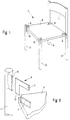
- the seating furniture shown in FIG. 1 represents a wooden chair with four vertical chair legs 2, 3, 4 and 5, of which the seat plate 6 is carried.
- the chair legs 4 and 5 protrude upward beyond the seat plate 6 and are connected to one another above the seat plate 6 by the backrest 7.
- Four slots 8 are provided in the seat plate 6, which protrude approximately in the diagonal direction into the seat plate 6.
- support bracket 9 see FIG. 2 are inserted, via the connection between the seat plate 6 and the chair legs 2 to 5 for the purpose of attachment.
- the support bracket 9 shown in FIG. 2 is inserted into a slot 10 in chair leg 3, which is described in more detail with reference to FIG. 2.
- Such a slot 10 is also present in the other chair legs 2, 4 and 5.
- FIG. 2 shows the connection of the chair legs 2 to 5 and the seat plate 6 according to FIG. 1 in an enlarged view.
- the chair leg 3 and the seat plate 6 are shown at a distance from one another in order to facilitate understanding in connection with the support bracket 9 drawn between them.
- the chair leg 3 is provided with the slot 10 which is aligned with the slot 8 in the seat plate 6 when the chair leg 3 and seat plate 6 are connected to one another by means of the support bracket 9.
- the leg 12 of the support bracket 9 is inserted into the slot 10 of the chair leg 3, the leg 12 being completely absorbed by the slot 10.
- the slot 10 has a corresponding depth for this.
- the seat plate 6 is pushed onto the leg 11 of the support bracket 9, the leg 11 being completely received by the slot 8.
- the slots 8 and 10 have such a width that the legs 11 and 12 completely fill the slots 8 and 10.
- the firm connection between the support bracket 9 and the chair leg 3 and the seat plate 6 is done by gluing between the legs 11 and 12 and the slots 8 and 10.
- the adhesive in question is expediently introduced beforehand into the slots 8 and 10, from which he then when the Legs 11 and 12 is pressed out, but a sufficiently thick adhesive film remains between the legs 11 and 12 and the walls of the slots 8 and 10, so that there is a stable connection, which is so firm when choosing a suitable adhesive that when overloaded rather the material of the seat plate 6 and the chair leg 3, here wood, breaks before the bond loosens.
- the slot 8 penetrates the seat plate 6 completely.
- the seat plate 6 and the support bracket 9 a position in the slot 8 results according to a corresponding dimensioning of the leg 11, according to which the leg 11 closes both with the seat surface and with the underside of the seat plate 6.
- the support bracket 9 In order to achieve a sufficient strength of the support bracket 9, it is expediently made of flat steel or a corresponding solid aluminum alloy. It is also possible to use a correspondingly hard plastic for this.
- FIGS. 1 and 2 The embodiment shown in FIGS. 1 and 2 is, as mentioned, a wooden chair 1, the seat plate 6 of which consists of a plywood plate with a thickness of approximately 25 mm.
- the seat plate 6 is due to its strength easily able to absorb the forces transmitted from the support bracket 9, because the Leg 11 of the support bracket 9 protrude into the seat plate 6 with a length such that there is a sufficient distribution of the transmitted forces along the leg 11.
- the length of the legs 11 corresponds to twice the thickness of the seat plate 6.
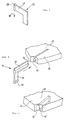
- FIG. 3 shows a support bracket 24 which has a thickening 26 at the end of its leg 25, which forms a profiling which extends transversely to the leg 25.
- the support bracket 24 is inserted into the seat plate in the direction of the arrow 28 shown. To enable this insertion, the slot in the seat plate is provided with an extension at its end.
- the thickening 26 gives the support bracket 24 inserted into the seat plate a certain support in order to give the necessary rest for the hardening of an adhesive film surrounding the leg 25. This also increases the adhesive area.
- the profile 33 running in the longitudinal direction is provided on the leg 32 of the support bracket 31, and the profile 35 is also provided on the leg 34.
- the profiles 33 and 35 are again thickened portions.
- the profile 33 is received by a corresponding recess 36 in the slot 37 of the relevant seat plate 38.
- the profiling 33 ensures that after inserting the leg 32 into the slot 37, the leg 32 initially receives a secure hold.
- FIG. 5 shows the seat plate 39, into which the slot 40 is let in, which here leaves the base 42 in relation to the seat surface 41.
- the slot 40 therefore only extends to the surface of the seat plate 39 opposite the seat surface 41.
- This introduction of the slot 40 has the result that an angle of support inserted into the slot 40 is not visible on the seat surface 41.
- the base 42 has only such a strength that a support angle inserted into the slot 40 extends essentially over the full strength of the seat plate 39, so that practically the full strength of the seat plate 39 is used for the introduction of forces into the seat plate 39.
- the support angles protruding into the respective seat plate are glued to the seat plate, the respective support angles being of such a strength that they completely fill the slot in question, but there is still enough space for gluing an adhesive film can form, which then ensures the firm connection between the support bracket and seat plate.
Landscapes
- Chair Legs, Seat Parts, And Backrests (AREA)
- Legs For Furniture In General (AREA)
- Furniture Connections (AREA)
- Special Chairs (AREA)
- Chairs For Special Purposes, Such As Reclining Chairs (AREA)
- Mattresses And Other Support Structures For Chairs And Beds (AREA)
Applications Claiming Priority (2)
| Application Number | Priority Date | Filing Date | Title |
|---|---|---|---|
| DE3914172A DE3914172A1 (de) | 1989-04-28 | 1989-04-28 | Sitzmoebel |
| DE3914172 | 1989-04-28 |
Publications (2)
| Publication Number | Publication Date |
|---|---|
| EP0470137A1 EP0470137A1 (de) | 1992-02-12 |
| EP0470137B1 true EP0470137B1 (de) | 1994-03-23 |
Family
ID=6379741
Family Applications (1)
| Application Number | Title | Priority Date | Filing Date |
|---|---|---|---|
| EP90906940A Expired - Lifetime EP0470137B1 (de) | 1989-04-28 | 1990-04-30 | Sitzmöbel |
Country Status (7)
| Country | Link |
|---|---|
| EP (1) | EP0470137B1 (da) |
| JP (1) | JP2775344B2 (da) |
| AT (1) | ATE103148T1 (da) |
| DE (2) | DE3914172A1 (da) |
| DK (1) | DK0470137T3 (da) |
| ES (1) | ES2050436T3 (da) |
| WO (1) | WO1990013243A1 (da) |
Families Citing this family (4)
| Publication number | Priority date | Publication date | Assignee | Title |
|---|---|---|---|---|
| JP3661444B2 (ja) * | 1998-10-28 | 2005-06-15 | 株式会社ルネサステクノロジ | 半導体装置、半導体ウエハ、半導体モジュールおよび半導体装置の製造方法 |
| DE202008000014U1 (de) | 2008-02-24 | 2008-07-17 | Michael, Ingolf | Sitzmöbel aus Holz mit einer Sitzfläche, Rückenlehne und vier Stuhlbeinen |
| CN105534117A (zh) * | 2016-02-03 | 2016-05-04 | 黄乃云 | 斜对角二分工艺法插叠方凳 |
| FR3101082B1 (fr) | 2019-09-24 | 2021-10-08 | Ifp Energies Now | Procédé intégré d’hydrocraquage en lit fixe et d’hydroconversion en lit bouillonnant avec une séparation gaz/liquide améliorée |
Family Cites Families (3)
| Publication number | Priority date | Publication date | Assignee | Title |
|---|---|---|---|---|
| GB379177A (en) * | 1931-10-07 | 1932-08-25 | Anna Leinenkugel | Improvements in and relating to chairs |
| DE1889518U (de) * | 1964-01-17 | 1964-03-19 | Thonet A G Geb | Sitzmoebel mit rueckenlehne. |
| DE8717552U1 (de) * | 1987-04-13 | 1989-03-30 | Kusch & Co Sitzmoebelwerke Kg, 5789 Hallenberg | Sitzmöbel |
-
1989
- 1989-04-28 DE DE3914172A patent/DE3914172A1/de active Granted
-
1990
- 1990-04-30 EP EP90906940A patent/EP0470137B1/de not_active Expired - Lifetime
- 1990-04-30 WO PCT/EP1990/000692 patent/WO1990013243A1/de not_active Ceased
- 1990-04-30 DK DK90906940.3T patent/DK0470137T3/da active
- 1990-04-30 DE DE90906940T patent/DE59005133D1/de not_active Expired - Fee Related
- 1990-04-30 JP JP2506575A patent/JP2775344B2/ja not_active Expired - Lifetime
- 1990-04-30 ES ES90906940T patent/ES2050436T3/es not_active Expired - Lifetime
- 1990-04-30 AT AT90906940T patent/ATE103148T1/de not_active IP Right Cessation
Also Published As
| Publication number | Publication date |
|---|---|
| DE3914172A1 (de) | 1990-10-31 |
| ATE103148T1 (de) | 1994-04-15 |
| JPH04504669A (ja) | 1992-08-20 |
| DK0470137T3 (da) | 1994-05-02 |
| ES2050436T3 (es) | 1994-05-16 |
| EP0470137A1 (de) | 1992-02-12 |
| JP2775344B2 (ja) | 1998-07-16 |
| DE3914172C2 (da) | 1991-10-24 |
| DE59005133D1 (de) | 1994-04-28 |
| WO1990013243A1 (de) | 1990-11-15 |
Similar Documents
| Publication | Publication Date | Title |
|---|---|---|
| DE2633972A1 (de) | Verbindungsanordnung fuer moebel | |
| DE2525791A1 (de) | Moebelsystem auf der basis von gestellen und profilen | |
| DE3108649A1 (de) | Stossstange fuer kraftfahrzeuge | |
| DE9000543U1 (de) | Zerlegbares Möbel, beispielsweise Regal | |
| EP0470137B1 (de) | Sitzmöbel | |
| EP0169262A1 (de) | Stuhl | |
| DE2823772A1 (de) | Konstruktionselement fuer drei-dimensionale gegenstaende, z.b. moebel | |
| DE2900065A1 (de) | Holztraeger | |
| DE7516704U (de) | Gestell, insbesondere für Werbung und Verkauf | |
| EP0160814B1 (de) | Verbinder, insbesondere für Möbel | |
| EP0371237A2 (de) | Bausatz für eine Türzarge | |
| DE2356850A1 (de) | Keilverbindung fuer zumindest zwei senkrecht zueinander angeordnete bauelemente sowie unter anwendung solcher verbindungen erstellte konstruktionen und gerueste | |
| DE3523658C2 (da) | ||
| DE1978738U (de) | Bauelement zum herstellen von moebeln, waenden od. dgl. | |
| DE69319146T2 (de) | Zusammenstellbare regaleinheit | |
| DE3203584C2 (de) | Schalung für eine einen Unterzug aufweisende Betondecke | |
| DE10064949C1 (de) | Bausatz für eine Fertigteil-Stützmauer | |
| EP0197248B1 (de) | Unterzugschalung | |
| AT238423B (de) | Knotenpunktverbindung, insbesondere für Holzkonstruktionen | |
| DE9018166U1 (de) | Plattenartiges Bauelement, insbesondere für Leichtbaumöbel | |
| DE1225833B (de) | Zerlegbarer Holztragrost | |
| DE3348076C2 (en) | Concrete shuttering comprising shuttering panels connected with turnbuckles | |
| CH685719A5 (de) | Möbel mit Beinen. | |
| DE7518492U (de) | Bausatz für Möbel | |
| DE3712524A1 (de) | Sitzmoebel |
Legal Events
| Date | Code | Title | Description |
|---|---|---|---|
| PUAI | Public reference made under article 153(3) epc to a published international application that has entered the european phase |
Free format text: ORIGINAL CODE: 0009012 |
|
| 17P | Request for examination filed |
Effective date: 19910917 |
|
| AK | Designated contracting states |
Kind code of ref document: A1 Designated state(s): AT BE CH DE DK ES FR GB IT LI NL SE |
|
| 17Q | First examination report despatched |
Effective date: 19930514 |
|
| GRAA | (expected) grant |
Free format text: ORIGINAL CODE: 0009210 |
|
| AK | Designated contracting states |
Kind code of ref document: B1 Designated state(s): AT BE CH DE DK ES FR GB IT LI NL SE |
|
| REF | Corresponds to: |
Ref document number: 103148 Country of ref document: AT Date of ref document: 19940415 Kind code of ref document: T |
|
| REF | Corresponds to: |
Ref document number: 59005133 Country of ref document: DE Date of ref document: 19940428 |
|
| REG | Reference to a national code |
Ref country code: DK Ref legal event code: T3 |
|
| REG | Reference to a national code |
Ref country code: ES Ref legal event code: FG2A Ref document number: 2050436 Country of ref document: ES Kind code of ref document: T3 |
|
| ITF | It: translation for a ep patent filed | ||
| GBT | Gb: translation of ep patent filed (gb section 77(6)(a)/1977) |
Effective date: 19940510 |
|
| ET | Fr: translation filed | ||
| PLBE | No opposition filed within time limit |
Free format text: ORIGINAL CODE: 0009261 |
|
| STAA | Information on the status of an ep patent application or granted ep patent |
Free format text: STATUS: NO OPPOSITION FILED WITHIN TIME LIMIT |
|
| EAL | Se: european patent in force in sweden |
Ref document number: 90906940.3 |
|
| 26N | No opposition filed | ||
| PGFP | Annual fee paid to national office [announced via postgrant information from national office to epo] |
Ref country code: DK Payment date: 19950419 Year of fee payment: 6 |
|
| PGFP | Annual fee paid to national office [announced via postgrant information from national office to epo] |
Ref country code: AT Payment date: 19950420 Year of fee payment: 6 |
|
| PGFP | Annual fee paid to national office [announced via postgrant information from national office to epo] |
Ref country code: ES Payment date: 19950428 Year of fee payment: 6 |
|
| PGFP | Annual fee paid to national office [announced via postgrant information from national office to epo] |
Ref country code: NL Payment date: 19950430 Year of fee payment: 6 |
|
| PGFP | Annual fee paid to national office [announced via postgrant information from national office to epo] |
Ref country code: BE Payment date: 19950510 Year of fee payment: 6 |
|
| PG25 | Lapsed in a contracting state [announced via postgrant information from national office to epo] |
Ref country code: DK Effective date: 19960430 Ref country code: BE Effective date: 19960430 Ref country code: AT Effective date: 19960430 |
|
| REG | Reference to a national code |
Ref country code: DK Ref legal event code: EBP |
|
| PG25 | Lapsed in a contracting state [announced via postgrant information from national office to epo] |
Ref country code: ES Free format text: LAPSE BECAUSE OF NON-PAYMENT OF DUE FEES Effective date: 19960503 |
|
| BERE | Be: lapsed |
Owner name: LOHMEYER HARTMUT Effective date: 19960430 |
|
| PG25 | Lapsed in a contracting state [announced via postgrant information from national office to epo] |
Ref country code: NL Effective date: 19961101 |
|
| NLV4 | Nl: lapsed or anulled due to non-payment of the annual fee |
Effective date: 19961101 |
|
| PGFP | Annual fee paid to national office [announced via postgrant information from national office to epo] |
Ref country code: GB Payment date: 19970415 Year of fee payment: 8 |
|
| PGFP | Annual fee paid to national office [announced via postgrant information from national office to epo] |
Ref country code: FR Payment date: 19970417 Year of fee payment: 8 |
|
| PGFP | Annual fee paid to national office [announced via postgrant information from national office to epo] |
Ref country code: CH Payment date: 19970421 Year of fee payment: 8 |
|
| PGFP | Annual fee paid to national office [announced via postgrant information from national office to epo] |
Ref country code: SE Payment date: 19970422 Year of fee payment: 8 |
|
| PG25 | Lapsed in a contracting state [announced via postgrant information from national office to epo] |
Ref country code: LI Free format text: LAPSE BECAUSE OF NON-PAYMENT OF DUE FEES Effective date: 19980430 Ref country code: GB Free format text: LAPSE BECAUSE OF NON-PAYMENT OF DUE FEES Effective date: 19980430 Ref country code: FR Free format text: THE PATENT HAS BEEN ANNULLED BY A DECISION OF A NATIONAL AUTHORITY Effective date: 19980430 Ref country code: CH Free format text: LAPSE BECAUSE OF NON-PAYMENT OF DUE FEES Effective date: 19980430 |
|
| PG25 | Lapsed in a contracting state [announced via postgrant information from national office to epo] |
Ref country code: SE Free format text: LAPSE BECAUSE OF NON-PAYMENT OF DUE FEES Effective date: 19980501 |
|
| REG | Reference to a national code |
Ref country code: CH Ref legal event code: PL |
|
| GBPC | Gb: european patent ceased through non-payment of renewal fee |
Effective date: 19980430 |
|
| EUG | Se: european patent has lapsed |
Ref document number: 90906940.3 |
|
| REG | Reference to a national code |
Ref country code: FR Ref legal event code: ST |
|
| REG | Reference to a national code |
Ref country code: ES Ref legal event code: FD2A Effective date: 19990405 |
|
| PGFP | Annual fee paid to national office [announced via postgrant information from national office to epo] |
Ref country code: DE Payment date: 20000529 Year of fee payment: 11 |
|
| PG25 | Lapsed in a contracting state [announced via postgrant information from national office to epo] |
Ref country code: DE Free format text: LAPSE BECAUSE OF NON-PAYMENT OF DUE FEES Effective date: 20020201 |
|
| PG25 | Lapsed in a contracting state [announced via postgrant information from national office to epo] |
Ref country code: IT Free format text: LAPSE BECAUSE OF NON-PAYMENT OF DUE FEES;WARNING: LAPSES OF ITALIAN PATENTS WITH EFFECTIVE DATE BEFORE 2007 MAY HAVE OCCURRED AT ANY TIME BEFORE 2007. THE CORRECT EFFECTIVE DATE MAY BE DIFFERENT FROM THE ONE RECORDED. Effective date: 20050430 |