EP0443375B1 - Lösbarer Spannverschluss einer Schaltschrank-Versteifungsvorrichtung - Google Patents
Lösbarer Spannverschluss einer Schaltschrank-Versteifungsvorrichtung Download PDFInfo
- Publication number
- EP0443375B1 EP0443375B1 EP91101713A EP91101713A EP0443375B1 EP 0443375 B1 EP0443375 B1 EP 0443375B1 EP 91101713 A EP91101713 A EP 91101713A EP 91101713 A EP91101713 A EP 91101713A EP 0443375 B1 EP0443375 B1 EP 0443375B1
- Authority
- EP
- European Patent Office
- Prior art keywords
- tensioning
- tensioned state
- angle
- lever
- switch cabinet
- Prior art date
- Legal status (The legal status is an assumption and is not a legal conclusion. Google has not performed a legal analysis and makes no representation as to the accuracy of the status listed.)
- Expired - Lifetime
Links
Images

Classifications
-
- H—ELECTRICITY
- H02—GENERATION; CONVERSION OR DISTRIBUTION OF ELECTRIC POWER
- H02B—BOARDS, SUBSTATIONS OR SWITCHING ARRANGEMENTS FOR THE SUPPLY OR DISTRIBUTION OF ELECTRIC POWER
- H02B1/00—Frameworks, boards, panels, desks, casings; Details of substations or switching arrangements
- H02B1/54—Anti-seismic devices or installations
-
- H—ELECTRICITY
- H02—GENERATION; CONVERSION OR DISTRIBUTION OF ELECTRIC POWER
- H02B—BOARDS, SUBSTATIONS OR SWITCHING ARRANGEMENTS FOR THE SUPPLY OR DISTRIBUTION OF ELECTRIC POWER
- H02B1/00—Frameworks, boards, panels, desks, casings; Details of substations or switching arrangements
- H02B1/26—Casings; Parts thereof or accessories therefor
- H02B1/30—Cabinet-type casings; Parts thereof or accessories therefor
Definitions
- the invention relates to a releasable tension lock of a control cabinet stiffening device, which consists of two angle braces and extends in the tension state X-shaped in one plane, the tension lock having a tension bolt, which is attached at one end to one of the angle struts and at the other end one Cross bore has on which a clamping block with a clamping lever is attached via a thru axle.
- a latch is known for example from DE-GM 81 01 241.
- the task of such stiffening devices is to suppress vibrations generated by an earthquake.
- a high bending moment acts on the tensioning bolt when the tensioning closure is opened. This bending moment leads to material overloads, so that the bolt when opening or under other loads, e.g. can break due to seismic load.
- the object of the invention is to avoid the disadvantage mentioned above, wherein as many parts as possible from the prior art described above should be used for reasons of cost.
- transverse bore extends perpendicular to the plane formed by the stiffening device in the tensioned state, so that the clamping block and tensioning lever can be pivoted in the plane formed by the stiffening device in the tensioned state and act on the other angle strut in the tensioned state.
- the clamping lever has a kink in the vicinity of the clamping block, so that there is still a free space between the angle strut on the side of the clamping block and the clamping lever in both lever positions (OPEN and CLOSE), so that the clamping lever has no risk of injury can be operated.
- the tension lock is advantageously designed such that the tension lever is moved downward for tensioning the tension lock. This prevents e.g. during a seismic excitation the tension lock is opened and the stiffening device is rendered ineffective.
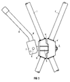
- Two angle struts 1, 1 'of a stiffening device are pivotally attached in a control cabinet 2 releasably.
- FIGS. 2 and 3 show the structure of the tension lock 3, which connects the two central parts 4, 4 'of the angle struts 1, 1' with each other.
- a clamping bolt 5 is rigidly attached at one end to the central part 4 'of the angle strut 1'.
- a groove is made which guides the clamping bolt 5.
- the bore in the clamping block 7 for the thru axle is advantageously arranged eccentrically, as indicated in FIGS. 2 and 3.
- the tensioning lever 8 By pivoting the tensioning lever 8 in the plane formed by the stiffening device in the tensioned state, the tensioning lock 3 is relaxed or relaxed.
- the tensioning lever 8 has a kink K such that the tensioning lever 8 encloses an acute angle with the angle strut 1 both when the tensioning lock 4 is tensioned and when it is released.
- the kink K it is possible to use the parts designed for a turnbuckle according to DE-GM 81 01 241 almost unchanged, thus avoiding an expensive new development.
- the tensioning block 7 should be designed in such a way that the tension lock 3 is tensioned downward by a movement of the tensioning lever 8, since then falling objects cannot release the tension lock 3.
- a pad 9 arranged between the clamping block 7 and the middle part 4 of the angle strut 1 distributes the pressure evenly over the middle part of the angle strut 1, so that even without changes to the middle part 4 of the angle strut 1 in the clamping bolt 5 there are no more bending forces.
Landscapes
- Engineering & Computer Science (AREA)
- Power Engineering (AREA)
- Clamps And Clips (AREA)
Applications Claiming Priority (2)
| Application Number | Priority Date | Filing Date | Title |
|---|---|---|---|
| DE9001997U DE9001997U1 (de) | 1990-02-20 | 1990-02-20 | Lösbarer Spannverschluß einer Schaltschrank-Versteifungsvorrichtung |
| DE9001997U | 1990-02-20 |
Publications (2)
| Publication Number | Publication Date |
|---|---|
| EP0443375A1 EP0443375A1 (de) | 1991-08-28 |
| EP0443375B1 true EP0443375B1 (de) | 1995-07-05 |
Family
ID=6851208
Family Applications (1)
| Application Number | Title | Priority Date | Filing Date |
|---|---|---|---|
| EP91101713A Expired - Lifetime EP0443375B1 (de) | 1990-02-20 | 1991-02-07 | Lösbarer Spannverschluss einer Schaltschrank-Versteifungsvorrichtung |
Country Status (2)
| Country | Link |
|---|---|
| EP (1) | EP0443375B1 (nl) |
| DE (2) | DE9001997U1 (nl) |
Families Citing this family (2)
| Publication number | Priority date | Publication date | Assignee | Title |
|---|---|---|---|---|
| DE9112108U1 (de) * | 1991-09-27 | 1992-10-29 | Siemens AG, 8000 München | Metallschrank zur Aufnahme von elektrotechnischen Bauteilen mit einstellbarer Versteifungsvorrichtung |
| PL2159336T3 (pl) | 2007-06-29 | 2013-09-30 | Geberit Int Ag | Zastosowanie odpływu dennego |
Family Cites Families (3)
| Publication number | Priority date | Publication date | Assignee | Title |
|---|---|---|---|---|
| DE2736163C2 (de) * | 1977-08-11 | 1982-06-09 | Schoppe & Faeser Gmbh, 4950 Minden | Schrank mit einem aus Profilschienen aufgebauten äußeren Käfig |
| DE8101241U1 (de) * | 1981-01-20 | 1981-06-04 | Siemens AG, 1000 Berlin und 8000 München | Versteifungsvorrichtung für einen Elektronikschrank |
| DE3722296A1 (de) * | 1987-07-06 | 1989-01-19 | Siemens Ag | Versteifungsvorrichtung fuer einen elektronikschrank |
-
1990
- 1990-02-20 DE DE9001997U patent/DE9001997U1/de not_active Expired - Lifetime
-
1991
- 1991-02-07 EP EP91101713A patent/EP0443375B1/de not_active Expired - Lifetime
- 1991-02-07 DE DE59105894T patent/DE59105894D1/de not_active Expired - Fee Related
Also Published As
| Publication number | Publication date |
|---|---|
| DE9001997U1 (de) | 1990-04-26 |
| DE59105894D1 (de) | 1995-08-10 |
| EP0443375A1 (de) | 1991-08-28 |
Similar Documents
| Publication | Publication Date | Title |
|---|---|---|
| DE2119480A1 (de) | Vorrichtung zum Umschlagen von Lasten | |
| EP0443375B1 (de) | Lösbarer Spannverschluss einer Schaltschrank-Versteifungsvorrichtung | |
| DE2511610A1 (de) | Kippbarer tiegel oder konverter | |
| DE1580485C3 (de) | Vorrichtung zum Verriegeln des hinteren Endes eines kippbaren Fahrerhauses | |
| DE8031715U1 (de) | Verriegelungsvorrichtung an koksofentueren | |
| DE3541195C2 (de) | Vorrichtung zum Abspannen oder Halten von Hochspannungsfreileitungen | |
| DE3907200C1 (en) | Self-tightening and self-locking lifting tongs for load-lifting appliances | |
| AT247950B (de) | Schaltschloß für elektrische und mechanische Schalter | |
| DE1156211B (de) | Vorrichtung zum Messen und UEberwachen des Lastmomentes an Krananlagen od. dgl. | |
| DE673445C (de) | Verfahren und Vorrichtung zum Zusammenhalten mehrerer Bauteile | |
| DE800460C (de) | Selbstsichernder Spannhebelverschluss fuer klappbare Fahrzeugwaende | |
| DE1200915B (de) | Kipp-Trennschalter | |
| DE1552629C (de) | Einspannvorrichtung fur Werk zeuge | |
| DE7800627U1 (de) | Bremselement für Abstandhalter an Zweifach-Isolatorenketten | |
| DE1199551B (de) | Aussenbackenbremse | |
| DE732252C (de) | Mittel zum Sichern von Isolatorbefestigungen | |
| DE1275257B (de) | Sicherheitseinrichtung fuer Arbeitsgeraete, insbesondere Hebezeuge | |
| DE1450187C (de) | Bandbremse | |
| DE2001653C (de) | Kraftfahrzeug Turverschlußgehause | |
| DE9310038U1 (de) | Lastschließender Transportgreifer | |
| DE102019111104A1 (de) | Hebeklemme | |
| AT37426B (de) | Plättgestell in Schränkchenform. | |
| DE7704885U1 (de) | Riegelkette fuer rundschalungen | |
| DE7427993U (de) | Vorrichtung zum Greifen und Heben von Lasten | |
| DE2104385A1 (de) | Vorrichtung zur Verriegelung eines Organs gegenüber seiner Halterung, auf der es durch sein Eigengewicht ruht |
Legal Events
| Date | Code | Title | Description |
|---|---|---|---|
| PUAI | Public reference made under article 153(3) epc to a published international application that has entered the european phase |
Free format text: ORIGINAL CODE: 0009012 |
|
| AK | Designated contracting states |
Kind code of ref document: A1 Designated state(s): CH DE ES FR GB GR LI SE |
|
| 17P | Request for examination filed |
Effective date: 19911008 |
|
| 17Q | First examination report despatched |
Effective date: 19940708 |
|
| GRAA | (expected) grant |
Free format text: ORIGINAL CODE: 0009210 |
|
| AK | Designated contracting states |
Kind code of ref document: B1 Designated state(s): CH DE ES FR GB GR LI SE |
|
| PG25 | Lapsed in a contracting state [announced via postgrant information from national office to epo] |
Ref country code: GR Free format text: LAPSE BECAUSE OF FAILURE TO SUBMIT A TRANSLATION OF THE DESCRIPTION OR TO PAY THE FEE WITHIN THE PRESCRIBED TIME-LIMIT Effective date: 19950705 Ref country code: GB Effective date: 19950705 Ref country code: FR Effective date: 19950705 Ref country code: ES Free format text: THE PATENT HAS BEEN ANNULLED BY A DECISION OF A NATIONAL AUTHORITY Effective date: 19950705 |
|
| REF | Corresponds to: |
Ref document number: 59105894 Country of ref document: DE Date of ref document: 19950810 |
|
| PG25 | Lapsed in a contracting state [announced via postgrant information from national office to epo] |
Ref country code: SE Effective date: 19951005 |
|
| EN | Fr: translation not filed | ||
| GBV | Gb: ep patent (uk) treated as always having been void in accordance with gb section 77(7)/1977 [no translation filed] |
Effective date: 19950705 |
|
| PG25 | Lapsed in a contracting state [announced via postgrant information from national office to epo] |
Ref country code: LI Free format text: LAPSE BECAUSE OF NON-PAYMENT OF DUE FEES Effective date: 19960228 Ref country code: CH Free format text: LAPSE BECAUSE OF NON-PAYMENT OF DUE FEES Effective date: 19960228 |
|
| PLBE | No opposition filed within time limit |
Free format text: ORIGINAL CODE: 0009261 |
|
| STAA | Information on the status of an ep patent application or granted ep patent |
Free format text: STATUS: NO OPPOSITION FILED WITHIN TIME LIMIT |
|
| 26N | No opposition filed | ||
| REG | Reference to a national code |
Ref country code: CH Ref legal event code: PL |
|
| PG25 | Lapsed in a contracting state [announced via postgrant information from national office to epo] |
Ref country code: DE Effective date: 19961101 |