EP0443375B1 - Detachable strain locking for a switch cabinet stiffening arrangement - Google Patents
Detachable strain locking for a switch cabinet stiffening arrangement Download PDFInfo
- Publication number
- EP0443375B1 EP0443375B1 EP91101713A EP91101713A EP0443375B1 EP 0443375 B1 EP0443375 B1 EP 0443375B1 EP 91101713 A EP91101713 A EP 91101713A EP 91101713 A EP91101713 A EP 91101713A EP 0443375 B1 EP0443375 B1 EP 0443375B1
- Authority
- EP
- European Patent Office
- Prior art keywords
- tensioning
- tensioned state
- angle
- lever
- switch cabinet
- Prior art date
- Legal status (The legal status is an assumption and is not a legal conclusion. Google has not performed a legal analysis and makes no representation as to the accuracy of the status listed.)
- Expired - Lifetime
Links
Images

Classifications
-
- H—ELECTRICITY
- H02—GENERATION; CONVERSION OR DISTRIBUTION OF ELECTRIC POWER
- H02B—BOARDS, SUBSTATIONS OR SWITCHING ARRANGEMENTS FOR THE SUPPLY OR DISTRIBUTION OF ELECTRIC POWER
- H02B1/00—Frameworks, boards, panels, desks, casings; Details of substations or switching arrangements
- H02B1/54—Anti-seismic devices or installations
-
- H—ELECTRICITY
- H02—GENERATION; CONVERSION OR DISTRIBUTION OF ELECTRIC POWER
- H02B—BOARDS, SUBSTATIONS OR SWITCHING ARRANGEMENTS FOR THE SUPPLY OR DISTRIBUTION OF ELECTRIC POWER
- H02B1/00—Frameworks, boards, panels, desks, casings; Details of substations or switching arrangements
- H02B1/26—Casings; Parts thereof or accessories therefor
- H02B1/30—Cabinet-type casings; Parts thereof or accessories therefor
Definitions
- the invention relates to a releasable tension lock of a control cabinet stiffening device, which consists of two angle braces and extends in the tension state X-shaped in one plane, the tension lock having a tension bolt, which is attached at one end to one of the angle struts and at the other end one Cross bore has on which a clamping block with a clamping lever is attached via a thru axle.
- a latch is known for example from DE-GM 81 01 241.
- the task of such stiffening devices is to suppress vibrations generated by an earthquake.
- a high bending moment acts on the tensioning bolt when the tensioning closure is opened. This bending moment leads to material overloads, so that the bolt when opening or under other loads, e.g. can break due to seismic load.
- the object of the invention is to avoid the disadvantage mentioned above, wherein as many parts as possible from the prior art described above should be used for reasons of cost.
- transverse bore extends perpendicular to the plane formed by the stiffening device in the tensioned state, so that the clamping block and tensioning lever can be pivoted in the plane formed by the stiffening device in the tensioned state and act on the other angle strut in the tensioned state.
- the clamping lever has a kink in the vicinity of the clamping block, so that there is still a free space between the angle strut on the side of the clamping block and the clamping lever in both lever positions (OPEN and CLOSE), so that the clamping lever has no risk of injury can be operated.
- the tension lock is advantageously designed such that the tension lever is moved downward for tensioning the tension lock. This prevents e.g. during a seismic excitation the tension lock is opened and the stiffening device is rendered ineffective.
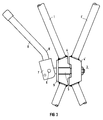
- Two angle struts 1, 1 'of a stiffening device are pivotally attached in a control cabinet 2 releasably.
- FIGS. 2 and 3 show the structure of the tension lock 3, which connects the two central parts 4, 4 'of the angle struts 1, 1' with each other.
- a clamping bolt 5 is rigidly attached at one end to the central part 4 'of the angle strut 1'.
- a groove is made which guides the clamping bolt 5.
- the bore in the clamping block 7 for the thru axle is advantageously arranged eccentrically, as indicated in FIGS. 2 and 3.
- the tensioning lever 8 By pivoting the tensioning lever 8 in the plane formed by the stiffening device in the tensioned state, the tensioning lock 3 is relaxed or relaxed.
- the tensioning lever 8 has a kink K such that the tensioning lever 8 encloses an acute angle with the angle strut 1 both when the tensioning lock 4 is tensioned and when it is released.
- the kink K it is possible to use the parts designed for a turnbuckle according to DE-GM 81 01 241 almost unchanged, thus avoiding an expensive new development.
- the tensioning block 7 should be designed in such a way that the tension lock 3 is tensioned downward by a movement of the tensioning lever 8, since then falling objects cannot release the tension lock 3.
- a pad 9 arranged between the clamping block 7 and the middle part 4 of the angle strut 1 distributes the pressure evenly over the middle part of the angle strut 1, so that even without changes to the middle part 4 of the angle strut 1 in the clamping bolt 5 there are no more bending forces.
Landscapes
- Engineering & Computer Science (AREA)
- Power Engineering (AREA)
- Clamps And Clips (AREA)
Description
Die Erfindung betrifft einen lösbaren Spannverschluß einer Schaltschrank-Versteifungsvorrichtung, die aus zwei Winkelstreben besteht und im Spannzustand X-förmig in einer Ebene verläuft, wobei der Spannverschluß einen Spannbolzen aufweist, der mit seinem einen Ende an einer der Winkelstreben befestigt ist und am anderen Ende eine Querbohrung aufweist an welcher über eine Steckachse ein Spannblock mit Spannhebel befestigt ist. Ein solcher Spannverschluß ist beispielsweise aus dem DE-GM 81 01 241 bekannt. Aufgabe solcher Versteifungsvorrichtungen ist die Unterdrückung von durch ein Erdbeben erzeugten Schwingungen. Bei der beschriebenen Anordnung zum Verspannen der Versteifungsvorrichtung ist jedoch nachteilig, daß beim Öffnen des Spannverschlusses ein hohes Biegemoment auf den Spannbolzen einwirkt. Dieses Biegemoment führt zu Materialüberlastungen, so daß der Bolzen beim Öffnen oder bei anderweitiger Belastung, z.B. durch seismische Belastung brechen kann.The invention relates to a releasable tension lock of a control cabinet stiffening device, which consists of two angle braces and extends in the tension state X-shaped in one plane, the tension lock having a tension bolt, which is attached at one end to one of the angle struts and at the other end one Cross bore has on which a clamping block with a clamping lever is attached via a thru axle. Such a latch is known for example from DE-GM 81 01 241. The task of such stiffening devices is to suppress vibrations generated by an earthquake. In the described arrangement for bracing the stiffening device, however, it is disadvantageous that a high bending moment acts on the tensioning bolt when the tensioning closure is opened. This bending moment leads to material overloads, so that the bolt when opening or under other loads, e.g. can break due to seismic load.
Aufgabe der Erfindung ist es, den oben genannten Nachteil zu vermeiden, wobei aus Kostengründen möglichst viele Teile aus oben beschriebenem Stand der Technik verwendet werden sollen. Insbesondere soll es möglich sein, eine gemäß dem DE-GM 81 01 241 ausgebildete Versteifungsvorrichtung mit dem erfindungsgemäßen Spannverschluß nachzurüsten.The object of the invention is to avoid the disadvantage mentioned above, wherein as many parts as possible from the prior art described above should be used for reasons of cost. In particular, it should be possible to retrofit a stiffening device designed according to DE-GM 81 01 241 with the tension lock according to the invention.
Die Aufgabe wird dadurch gelöst, daß die Querbohrung senkrecht zu der im Spannzustand von der Versteifungsvorrichtung gebildeten Ebene verläuft, so daß Spannblock und Spannhebel in der im Spannzustand von der Versteifungsvorrichtung gebildeten Ebene verschwenkbar sind und im Spannzustand auf die andere Winkelstrebe einwirken. Durch diese Maßnahmen wird erreicht, daß beim Betätigen des Spannverschlusses im Spannbolzen nur noch Zugkräfte auftreten, so daß Materialüberlastungen durch das Biegemoment vermieden werden.The object is achieved in that the transverse bore extends perpendicular to the plane formed by the stiffening device in the tensioned state, so that the clamping block and tensioning lever can be pivoted in the plane formed by the stiffening device in the tensioned state and act on the other angle strut in the tensioned state. These measures ensure that when you press the Tension lock in the clamping bolt only tensile forces occur so that material overloads due to the bending moment are avoided.
In einer vorteilhaften Ausgestaltung der Erfindung weist der Spannhebel in der Nähe des Spannblocks eine Abknickung auf, so daß zwischen der Winkelstrebe auf der Seite des Spannblocks und dem Spannhebel in beiden Hebelstellungen (AUF und ZU) noch ein Freiraum verbleibt, so daß der Spannhebel ohne Verletzungsgefahr betätigt werden kann.In an advantageous embodiment of the invention, the clamping lever has a kink in the vicinity of the clamping block, so that there is still a free space between the angle strut on the side of the clamping block and the clamping lever in both lever positions (OPEN and CLOSE), so that the clamping lever has no risk of injury can be operated.
Ferner ist mit Vorteil der Spannverschluß so gestaltet, daß zum Spannen des Spannverschlusses der Spannhebel nach unten bewegt wird. Dadurch wird verhindert, daß z.B. während einer seismischen Anregung der Spannverschluß geöffnet wird und so die Versteifungsvorrichtung wirkungslos gemacht wird.Furthermore, the tension lock is advantageously designed such that the tension lever is moved downward for tensioning the tension lock. This prevents e.g. during a seismic excitation the tension lock is opened and the stiffening device is rendered ineffective.
Weitere Vorteile ergeben sich durch die Anordnung einer Unterlage zwischen dem Spannblock und dem Mittelteil der Winkelstrebe, da hierdurch der Anpreßdruck des Spannbolzens auf das Mittelteil der Winkelstrebe gleichmäßig und großflächig verteilt wird.Further advantages result from the arrangement of a base between the clamping block and the central part of the angle strut, since this causes the contact pressure of the clamping bolt to be distributed uniformly and over a large area on the central part of the angle strut.
Zur Erläuterung der Erfindung wird im folgenden ein Ausführungsbeispiel näher beschrieben. Es zeigen:
- FIG 1
- eine Ansicht der verspannten Versteifungsvorrichtung in einem Schaltschrank,
- FIG 2
- einen Schnitt durch den Spannverschluß im gespannten Zustand, und
- FIG 3
- eine Ansicht des Spannverschlusses im entspannten Zustand.
- FIG. 1
- a view of the braced stiffening device in a control cabinet,
- FIG 2
- a section through the tension lock in the tensioned state, and
- FIG 3
- a view of the tension lock in the relaxed state.
Zwei Winkelstreben 1, 1′ einer Versteifungsvorrichtung sind schwenkbar in einem Schaltschrank 2 lösbar befestigt. Die Winkelstreben 1, 1′ liegen dabei, wie in FIG 1 angedeutet, im gespannten Zustand X-förmig in einer Ebene.Two
Die Figuren 2 und 3 zeigen den Aufbau des Spannverschlusses 3, der die beiden Mittelteile 4, 4′ der Winkelstreben 1, 1′ miteinander verbindet. Ein Spannbolzen 5 ist mit seinem einen Ende starr am Mittelteil 4′ der Winkelstrebe 1′ befestigt. In das Mittelteil 4 der anderen Winkelstrebe 1 ist eine Nut eingebracht, die den Spannbolzen 5 führt. Am anderen Ende des Spannbolzens 5 befindet sich eine Querbohrung 6, die senkrecht zu der im Spannzustand von der Versteifungsvorrichtung gebildeten Ebene verläuft und an der über eine Steckachse der Spannblock 7 befestigt ist. Vorteilhaft ist die Bohrung im Spannblock 7 für die Steckachse exzentrisch angeordnet, wie in FIG 2 und 3 angedeutet.Figures 2 and 3 show the structure of the
Durch Verschwenken des Spannhebels 8 in der im Spannzustand von der Versteifungsvorrichtung gebildeten Ebene wird der Spannverschluß 3 ge- bzw. entspannt. Vorteilhaft weist der Spannhebel 8 dabei eine Abknickung K derart auf, daß der Spannhebel 8 mit der Winkelstrebe 1 sowohl bei gespannten als auch bei gelöstem Spannverschluß 4 einen spitzen Winkel einschließt. Durch die Abknickung K ist es möglich, die für einen Spannverschluß gemäß des DE-GM 81 01 241 ausgebildeten Teile nahezu unverändert zu verwenden, man vermeidet also eine kostspielige Neuentwicklung.By pivoting the tensioning lever 8 in the plane formed by the stiffening device in the tensioned state, the
Der Spannblock 7 sollte derart ausgebildet sein, daß der Spannverschluß 3 durch eine Bewegung des Spannhebels 8 nach unten gespannt wird, da dann herabfallende Gegenstände den Spannverschluß 3 nicht lösen können.The
Eine zwischen Spannblock 7 und Mittelteil 4 der Winkelstrebe 1 angeordnete Unterlage 9 verteilt den Druck gleichmäßig auf das Mittelteil der Winkelstrebe 1, so daß auch ohne Veränderungen am Mittelteil 4 der Winkelstrebe 1 im Spannbolzen 5 keine Biegekräfte mehr auftreten.A
Claims (3)
- A releasable strain lock of a switching cabinet reinforcing device which is formed by two angle struts and in its tensioned state extends in an X-shape in a plane, the strain lock comprising a tensioning bolt, which is secured at one end to one of the angle struts and at its other end comprises a transverse bore, to which a tensioning block with a tensioning lever is secured via a plug axle, characterised in that the transverse bore (6) extends perpendicular to the plane formed by the reinforcing device in its tensioned state, so that the tensioning block (7) and tensioning lever (8) are pivotable in the plane formed by the reinforcing device in its tensioned state and act upon the other angle strut in said tensioned state.
- A strain lock according to claim 1, characterised in that the tensioning lever (8) comprises a bend (K) in the vicinity of the tensioning block (7).
- A strain lock according to claim 1 or 2, characterised in that the tensioning lever (8) points at an angle towards the base of the switching cabinet (2) in the tensioned state.
Applications Claiming Priority (2)
| Application Number | Priority Date | Filing Date | Title |
|---|---|---|---|
| DE9001997U | 1990-02-20 | ||
| DE9001997U DE9001997U1 (en) | 1990-02-20 | 1990-02-20 | Detachable clamp lock of a control cabinet stiffening device |
Publications (2)
| Publication Number | Publication Date |
|---|---|
| EP0443375A1 EP0443375A1 (en) | 1991-08-28 |
| EP0443375B1 true EP0443375B1 (en) | 1995-07-05 |
Family
ID=6851208
Family Applications (1)
| Application Number | Title | Priority Date | Filing Date |
|---|---|---|---|
| EP91101713A Expired - Lifetime EP0443375B1 (en) | 1990-02-20 | 1991-02-07 | Detachable strain locking for a switch cabinet stiffening arrangement |
Country Status (2)
| Country | Link |
|---|---|
| EP (1) | EP0443375B1 (en) |
| DE (2) | DE9001997U1 (en) |
Families Citing this family (2)
| Publication number | Priority date | Publication date | Assignee | Title |
|---|---|---|---|---|
| DE9112108U1 (en) * | 1991-09-27 | 1992-10-29 | Siemens AG, 8000 München | Metal cabinet for storing electrical components with adjustable stiffening device |
| DK2009187T3 (en) | 2007-06-29 | 2010-08-16 | Geberit Int Ag | Sanitary installation with a floor drain and method for installing such a sanitary installation |
Family Cites Families (3)
| Publication number | Priority date | Publication date | Assignee | Title |
|---|---|---|---|---|
| DE2736163C2 (en) * | 1977-08-11 | 1982-06-09 | Schoppe & Faeser Gmbh, 4950 Minden | Cabinet with an outer cage made up of profile rails |
| DE8101241U1 (en) * | 1981-01-20 | 1981-06-04 | Siemens AG, 1000 Berlin und 8000 München | Reinforcement device for an electronics cabinet |
| DE3722296A1 (en) * | 1987-07-06 | 1989-01-19 | Siemens Ag | REINFORCING DEVICE FOR AN ELECTRONIC CABINET |
-
1990
- 1990-02-20 DE DE9001997U patent/DE9001997U1/en not_active Expired - Lifetime
-
1991
- 1991-02-07 EP EP91101713A patent/EP0443375B1/en not_active Expired - Lifetime
- 1991-02-07 DE DE59105894T patent/DE59105894D1/en not_active Expired - Fee Related
Also Published As
| Publication number | Publication date |
|---|---|
| DE9001997U1 (en) | 1990-04-26 |
| DE59105894D1 (en) | 1995-08-10 |
| EP0443375A1 (en) | 1991-08-28 |
Similar Documents
| Publication | Publication Date | Title |
|---|---|---|
| DE2119480A1 (en) | Device for handling loads | |
| EP0443375B1 (en) | Detachable strain locking for a switch cabinet stiffening arrangement | |
| DE2511610A1 (en) | TILTING CRUCIBLE OR CONVERTER | |
| DE1580485C3 (en) | Device for locking the rear end of a tilting cab | |
| DE8031715U1 (en) | LOCKING DEVICE ON COOKING DOORS | |
| DE3541195C2 (en) | Device for tensioning or holding high-voltage overhead lines | |
| DE3907200C1 (en) | Self-tightening and self-locking lifting tongs for load-lifting appliances | |
| AT247950B (en) | Switch lock for electrical and mechanical switches | |
| DE1156211B (en) | Device for measuring and monitoring the load torque on crane systems or the like. | |
| DE673445C (en) | Method and device for holding several components together | |
| DE800460C (en) | Self-locking tension lever lock for hinged vehicle walls | |
| AT262547B (en) | Adjustment device for support plates | |
| DE1200915B (en) | Toggle disconnector | |
| DE1552629C (en) | Clamping device for tools | |
| DE7800627U1 (en) | Brake element for spacers on double isolator chains | |
| DE1199551B (en) | External shoe brake | |
| DE732252C (en) | Means for securing isolator mountings | |
| DE1275257B (en) | Safety device for work equipment, especially lifting equipment | |
| DE1450187C (en) | Band brake | |
| DE2001653C (en) | Motor vehicle door lock housing | |
| DE9310038U1 (en) | Load-closing transport gripper | |
| DE102019111104A1 (en) | Lifting clamp | |
| AT37426B (en) | Flat frame in cabinet shape. | |
| DE7427993U (en) | Device for gripping and lifting loads | |
| DE2104385A1 (en) | Device for locking an organ with respect to its holder on which it rests by its own weight |
Legal Events
| Date | Code | Title | Description |
|---|---|---|---|
| PUAI | Public reference made under article 153(3) epc to a published international application that has entered the european phase |
Free format text: ORIGINAL CODE: 0009012 |
|
| AK | Designated contracting states |
Kind code of ref document: A1 Designated state(s): CH DE ES FR GB GR LI SE |
|
| 17P | Request for examination filed |
Effective date: 19911008 |
|
| 17Q | First examination report despatched |
Effective date: 19940708 |
|
| GRAA | (expected) grant |
Free format text: ORIGINAL CODE: 0009210 |
|
| AK | Designated contracting states |
Kind code of ref document: B1 Designated state(s): CH DE ES FR GB GR LI SE |
|
| PG25 | Lapsed in a contracting state [announced via postgrant information from national office to epo] |
Ref country code: GR Free format text: LAPSE BECAUSE OF FAILURE TO SUBMIT A TRANSLATION OF THE DESCRIPTION OR TO PAY THE FEE WITHIN THE PRESCRIBED TIME-LIMIT Effective date: 19950705 Ref country code: GB Effective date: 19950705 Ref country code: FR Effective date: 19950705 Ref country code: ES Free format text: THE PATENT HAS BEEN ANNULLED BY A DECISION OF A NATIONAL AUTHORITY Effective date: 19950705 |
|
| REF | Corresponds to: |
Ref document number: 59105894 Country of ref document: DE Date of ref document: 19950810 |
|
| PG25 | Lapsed in a contracting state [announced via postgrant information from national office to epo] |
Ref country code: SE Effective date: 19951005 |
|
| EN | Fr: translation not filed | ||
| GBV | Gb: ep patent (uk) treated as always having been void in accordance with gb section 77(7)/1977 [no translation filed] |
Effective date: 19950705 |
|
| PG25 | Lapsed in a contracting state [announced via postgrant information from national office to epo] |
Ref country code: LI Free format text: LAPSE BECAUSE OF NON-PAYMENT OF DUE FEES Effective date: 19960228 Ref country code: CH Free format text: LAPSE BECAUSE OF NON-PAYMENT OF DUE FEES Effective date: 19960228 |
|
| PLBE | No opposition filed within time limit |
Free format text: ORIGINAL CODE: 0009261 |
|
| STAA | Information on the status of an ep patent application or granted ep patent |
Free format text: STATUS: NO OPPOSITION FILED WITHIN TIME LIMIT |
|
| 26N | No opposition filed | ||
| REG | Reference to a national code |
Ref country code: CH Ref legal event code: PL |
|
| PG25 | Lapsed in a contracting state [announced via postgrant information from national office to epo] |
Ref country code: DE Effective date: 19961101 |