EP0443350B1 - Vorrichtung zum Aufspannen einer biegsamen Druckform auf einen Zylinder einer Rotationsdruckmaschine - Google Patents
Vorrichtung zum Aufspannen einer biegsamen Druckform auf einen Zylinder einer Rotationsdruckmaschine Download PDFInfo
- Publication number
- EP0443350B1 EP0443350B1 EP91101248A EP91101248A EP0443350B1 EP 0443350 B1 EP0443350 B1 EP 0443350B1 EP 91101248 A EP91101248 A EP 91101248A EP 91101248 A EP91101248 A EP 91101248A EP 0443350 B1 EP0443350 B1 EP 0443350B1
- Authority
- EP
- European Patent Office
- Prior art keywords
- clamping
- spindle
- channel
- plate
- cylinder
- Prior art date
- Legal status (The legal status is an assumption and is not a legal conclusion. Google has not performed a legal analysis and makes no representation as to the accuracy of the status listed.)
- Expired - Lifetime
Links
- 238000003780 insertion Methods 0.000 claims description 14
- 230000037431 insertion Effects 0.000 claims description 14
- 238000005452 bending Methods 0.000 claims description 3
- 238000005096 rolling process Methods 0.000 claims 1
- 238000004519 manufacturing process Methods 0.000 description 2
- 230000000284 resting effect Effects 0.000 description 2
- 230000003746 surface roughness Effects 0.000 description 2
- 238000004804 winding Methods 0.000 description 2
- 230000001154 acute effect Effects 0.000 description 1
- 230000001419 dependent effect Effects 0.000 description 1
- 238000011161 development Methods 0.000 description 1
- 230000018109 developmental process Effects 0.000 description 1
Images
Classifications
-
- B—PERFORMING OPERATIONS; TRANSPORTING
- B41—PRINTING; LINING MACHINES; TYPEWRITERS; STAMPS
- B41F—PRINTING MACHINES OR PRESSES
- B41F27/00—Devices for attaching printing elements or formes to supports
- B41F27/12—Devices for attaching printing elements or formes to supports for attaching flexible printing formes
- B41F27/1218—Devices for attaching printing elements or formes to supports for attaching flexible printing formes comprising printing plate tensioning devices
- B41F27/1225—Devices for attaching printing elements or formes to supports for attaching flexible printing formes comprising printing plate tensioning devices moving in the printing plate end substantially rectilinearly
- B41F27/1237—Devices for attaching printing elements or formes to supports for attaching flexible printing formes comprising printing plate tensioning devices moving in the printing plate end substantially rectilinearly by translatory motion substantially perpendicular to support surface
Definitions
- the invention relates to a device for clamping a flexible printing plate on a plate cylinder of a rotary printing press.
- a device for clamping a flexible printing plate on the plate cylinder of a rotary printing press in which a rotatable in a groove or pit of the plate cylinder winding rod or spindle by means of a gap introduced into the spindle, the rear end of the Pressure plate detected and in which the spindle with its outer surface jammed the hook-like bent front end of the pressure plate at the edge of the pit.
- the rear end of the pressure plate has a double bend, the portion of which forming the plate edge is inserted into the gap of the spindle.
- This device has the disadvantage that the channel formed in the surface of the cylinder must be relatively wide so that the pressure plate can be removed quickly and safely when unclamping.
- this device has the disadvantage that the rear end of the pressure plate is permanently deformed so much by the use of a winding rod that the pressure plate cannot be used repeatedly in every case.
- a cylindrical clamping channel houses an eccentrically mounted clamping spindle which, with its spindle body, presses the plate ends against a channel wall.
- the leading plate end must be folded and inserted into a slot in the clamping spindle so that it can be reliably grasped and pulled during clamping.
- the clamping channel must be made correspondingly wide.
- the ends of a flexible pressure plate are tensioned in the gap between a clamping spindle arranged in the cylinder pit and the space between the latter and the pit wall.
- the clamping spindle is supported with play in order to be able to clamp printing plates of different thicknesses. But here too the leading plate end is folded and inserted into a slot in the clamping spindle.
- the plate ends are gripped by the teeth of a centrally mounted clamping spindle in connection with a central and tangentially tapering pit wall.
- US-A-3276365 shows a plate clamping device in which the trailing plate end is gripped by a toothing of a clamping spindle in connection with the displaceable toothed rack.
- the centrally mounted clamping spindle is secured against bending by two support elements in the cylinder pit.
- the object of the invention is to provide a device for clamping flexible printing plates on plate cylinders so that the rear end of the printing plate need only be bent simply and at an obtuse angle, so that the insertion channel into which the two ends of the printing plate during clamping can be inserted, can be made narrower, and that the pressure plate can be tightened.
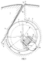
- the clamping device shown in FIG. 1 is essentially formed from a pit introduced into a plate cylinder 1, which has an insertion channel 2 and a cylindrical clamping channel 3 running parallel to the cylinder axis (not shown), and a clamping spindle 4 arranged axially parallel to the clamping channel 3.
- the effective width of the insertion channel 2 is identified by reference number 17.
- a wall of the insertion channel 2 has a segment 5 in the form of a segment of a circle, which is at the same time a segment of a circle of the circumferential circle of the clamping channel 3.
- the clamping spindle 4 has a cylindrical spindle body 6 and bearing journal 7, the axis 8 of the spindle body 6 being offset with respect to the axis 9 of the bearing journal 7.
- the clamping spindle 4 is arranged in the clamping channel 3 so that the axis 9 of the journal 7 is identical to the axis of the clamping channel 3. This results in an eccentric arrangement of the spindle body 6 in the clamping channel 3.
- a hole 11 or groove is made radially approximately in the middle of the clamping spindle, in which a support element 12 is arranged to limit the deflection of the clamping spindle.
- the support element 12 has a pin 13, a plurality of superimposed spring elements (14) (plate springs) guided by the pin 13 and a cylindrical roller 15 aligned axially parallel to the clamping spindle 4.
- the cylindrical roller 15 is pressed by the spring elements 14 against the wall of the clamping channel 3 and thus counteracts the deflection of the clamping spindle 4.
- the pin 13 limits the deflection of the clamping spindle 4 at the same time.
- the support element 12 can optionally also be formed by a helical spring or another elastic element and a cylindrical roller or ball resting directly on the helical spring or running in a roller cage resting on the helical spring. In this case, the deflection limitation results from the length of the fully compressed coil spring.
- the clamping spindle 4 When a printing plate 16 is clamped onto the plate cylinder 1, the front end of the printing plate 16 bent forward at an acute or right angle and the rear end of the printing plate 16 bent forward at an obtuse angle are inserted into the insertion channel 2. Then the clamping spindle 4 is rotated in a manner known per se, for example by means of a worm gear, in such a way that the spindle body 6 grasps the two ends of the pressure plate 16 and presses against the segment 5 in the form of a segment of a circle. 1, the clamping spindle 4 is thus rotated counterclockwise.
- the surface roughness of the spindle body 6 required here can be ensured either by the standard roughness or by a separate manufacturing step, such as flanging.
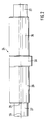
- FIG. 2 shows a schematic side view of a clamping spindle that can be used in the clamping device according to a second embodiment of the invention.
- the illustration of the plate cylinder 1, the insertion channel 2 and the clamping channel 3 and the plate ends of the pressure plate 16 is omitted for the sake of clarity, since this, like the arrangement and the functional principle of the clamping spindle 24, correspond to the corresponding features of the clamping spindle 4 from the first exemplary embodiment correspond.
- the clamping spindle 24 has a spindle body 26, bearing journal 27 and a support section 30 located on the spindle body 26.
- the axis 28 of the spindle body 26 is offset from the axis 29 of the journal 27, so that the clamping spindle 24 acts as an eccentric.
- the approximately in the middle of the spindle body 26 arranged support section 30 is cylindrical, its axis of rotation is identical to the axis 29 of the bearing journal 27 and its diameter is such that the support section 30 is arranged in the clamping channel 3 with a sliding fit, that is, in the clamping channel 3 is rotatably mounted.
- the clamping spindle 24 is correspondingly rotated in the first exemplary embodiment by means of a device known per se, such as a worm gear, in such a way that the eccentrically mounted spindle body 26 detects the two ends of the pressure plate 16 and so on pulls as far as possible into the insertion channel 2 and jams it on the segment 5 of the insertion channel 2 in the form of a segment of a circle.
- a device known per se such as a worm gear
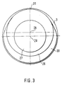
- Fig. 3 shows a schematic representation of an end view of the clamping spindle shown in Fig. 2. This view is shown in a highly schematic manner, in particular to show the flattening of the support section 30.
- the support section 30 is flattened from a reference point 31, at which the circumferential circle of the support section 30 and the circumferential circle of the spindle body 26 touch, from both directions over a range of 90 ° in each case.
Landscapes
- Supply, Installation And Extraction Of Printed Sheets Or Plates (AREA)
Applications Claiming Priority (2)
| Application Number | Priority Date | Filing Date | Title |
|---|---|---|---|
| DE4005093A DE4005093C1 (en) | 1990-02-17 | 1990-02-17 | Forme clamp for printing cylinder - has channel in cylinder with spindle to clamp form eccentrically |
| DE4005093 | 1990-02-17 |
Publications (2)
| Publication Number | Publication Date |
|---|---|
| EP0443350A1 EP0443350A1 (de) | 1991-08-28 |
| EP0443350B1 true EP0443350B1 (de) | 1994-12-21 |
Family
ID=6400437
Family Applications (1)
| Application Number | Title | Priority Date | Filing Date |
|---|---|---|---|
| EP91101248A Expired - Lifetime EP0443350B1 (de) | 1990-02-17 | 1991-01-31 | Vorrichtung zum Aufspannen einer biegsamen Druckform auf einen Zylinder einer Rotationsdruckmaschine |
Country Status (5)
| Country | Link |
|---|---|
| US (1) | US5062363A (ja) |
| EP (1) | EP0443350B1 (ja) |
| JP (1) | JP3001995B2 (ja) |
| CA (1) | CA2034427C (ja) |
| DE (2) | DE4005093C1 (ja) |
Families Citing this family (23)
| Publication number | Priority date | Publication date | Assignee | Title |
|---|---|---|---|---|
| DE4234332A1 (de) * | 1992-10-12 | 1994-04-14 | Heidelberger Druckmasch Ag | Aufspannvorrichtung zum Befestigen einer biegsamen Druckform auf der Mantelfläche eines Zylinders |
| DE4238343C2 (de) * | 1992-11-13 | 2003-03-27 | Kocher & Beck Gmbh & Co Rotati | Spannvorrichtung für ein Klischee |
| DE4401201C2 (de) * | 1994-01-18 | 1996-08-01 | Koenig & Bauer Albert Ag | Einrichtung zum Festhalten eines bogenförmigen Trägers |
| US5485784A (en) * | 1994-06-28 | 1996-01-23 | Walschlaeger, Sr.; Alan R. | Printing plate cylinder with universal lockup apparatus |
| DE19509561C2 (de) * | 1995-03-16 | 1997-10-23 | Koenig & Bauer Albert Ag | Vorrichtung zum Klemmen von Platten auf einem Zylinder |
| IT1282385B1 (it) * | 1995-05-05 | 1998-03-20 | Koenig & Bauer Albert Ag | Dispositivo per fissaggio di una unita' di tessuto gommato su un cilindro di una macchina da stampa rotativa |
| DE19521645C2 (de) * | 1995-06-14 | 1998-07-09 | Koenig & Bauer Albert Ag | Einrichtung für eine schlitzförmige Haltevorrichtung |
| DE19524296C2 (de) * | 1995-07-06 | 1997-05-15 | Koenig & Bauer Albert Ag | Zylinder |
| FR2737149B1 (fr) * | 1995-07-25 | 1997-10-17 | Heidelberg Harris Sa | Dispositif de fixation d'une plaque d'impression sur un cylindre porte-plaque |
| DE19533178C2 (de) * | 1995-09-08 | 1997-06-26 | Koenig & Bauer Albert Ag | Zylinder |
| DE29600845U1 (de) * | 1996-01-19 | 1996-03-07 | MAN Roland Druckmaschinen AG, 63075 Offenbach | Vorrichtung zum Befestigen einer Bespannung auf einem Druckwerkzylinder |
| DE19606744C2 (de) * | 1996-02-23 | 1998-12-10 | Roland Man Druckmasch | Vorrichtung zum Befestigen einer biegsamen Druckplatte |
| US5735211A (en) * | 1996-06-13 | 1998-04-07 | Mark Andy, Inc. | Clamping and tensioning device for printing plates |
| US5749298A (en) * | 1997-06-10 | 1998-05-12 | Reeves Brothers, Inc. | Arrangement for securing a printing blanket to a cylinder |
| US6131513A (en) * | 1998-10-23 | 2000-10-17 | Heidelberger Druckmaschinen Ag | Printing press with simple lock-up plate cylinder |
| US6378430B1 (en) | 1999-10-15 | 2002-04-30 | King Press Corporation | Cylinder with plate gripping device |
| DE10024331B4 (de) * | 2000-05-17 | 2005-08-18 | Koenig & Bauer Ag | Vorrichtung zum Klemmen und/oder Spannen |
| US6739961B2 (en) * | 2001-08-02 | 2004-05-25 | Donald E. Haney | Abrasive band tightening apparatus |
| TWM260360U (en) * | 2004-08-02 | 2005-04-01 | Ruei-Sen Liau | Tightening device for winding emery belt of spindle |
| JP4653981B2 (ja) * | 2004-08-10 | 2011-03-16 | 三菱重工印刷紙工機械株式会社 | 印刷機のブランケット胴 |
| EP2609026B1 (en) * | 2010-08-25 | 2018-08-01 | Hewlett-Packard Development Company, L.P. | Substrate support |
| JP6324076B2 (ja) * | 2014-01-10 | 2018-05-16 | 三菱重工機械システム株式会社 | ブランケット締め付け装置、ブランケット胴、印刷機 |
| US20220168868A1 (en) * | 2020-12-01 | 2022-06-02 | Fortune Extendables Corp. | Abrasive wheel which can be provided with a sandpaper |
Citations (1)
| Publication number | Priority date | Publication date | Assignee | Title |
|---|---|---|---|---|
| US3276365A (en) * | 1964-04-25 | 1966-10-04 | Roland Offsetmaschf | Printing plate clamping device for a printing press |
Family Cites Families (9)
| Publication number | Priority date | Publication date | Assignee | Title |
|---|---|---|---|---|
| US2279204A (en) * | 1940-12-13 | 1942-04-07 | Meisel Press Mfg Company | Printing cylinder |
| DE1196213B (de) * | 1959-11-12 | 1965-07-08 | American Type Founders Co Inc | Biegsame Druckplatte zum Aufspannen auf den Plattenzylinder einer Rotationsdruckmaschine und Biegevorrichtung zur Herstellung dieser Druckplatte |
| US3234694A (en) * | 1963-11-06 | 1966-02-15 | John F Vosburg | Abrasive strip holding and tightening mechanism |
| DE1561005A1 (de) * | 1966-10-01 | 1970-04-16 | Maschf Augsburg Nuernberg Ag | Vorrichtung zum Spannen von biegsamen Druckplatten auf dem Formzylinder von Rotationsdruckmaschinen |
| FR2478538A1 (fr) * | 1980-03-21 | 1981-09-25 | Creusot Loire | Dispositif pour corriger la position d'une plaque portee par un cylindre d'une machine d'impression |
| US4495865A (en) * | 1983-03-15 | 1985-01-29 | Komori Printing Machinery Co., Ltd. | Plate clamping device of web-fed rotary printing press |
| DE3326215C2 (de) * | 1983-07-21 | 1986-04-03 | M.A.N.- Roland Druckmaschinen AG, 6050 Offenbach | Vorrichtung zum Aufspannen einer Druckplatte oder eines Gummituches |
| DE3339185C2 (de) * | 1983-10-28 | 1986-01-30 | M.A.N.- Roland Druckmaschinen AG, 6050 Offenbach | Vorrichtung zum Spannen von Platten auf einen Formzylinder einer Rotationsdruckmaschine |
| EP0330736B2 (en) * | 1988-02-29 | 2000-01-19 | Goss Graphic Systems, Inc. | Tensionless plate lock-up |
-
1990
- 1990-02-17 DE DE4005093A patent/DE4005093C1/de not_active Expired - Lifetime
-
1991
- 1991-01-14 US US07/640,688 patent/US5062363A/en not_active Expired - Fee Related
- 1991-01-17 CA CA002034427A patent/CA2034427C/en not_active Expired - Fee Related
- 1991-01-31 DE DE59103943T patent/DE59103943D1/de not_active Expired - Fee Related
- 1991-01-31 EP EP91101248A patent/EP0443350B1/de not_active Expired - Lifetime
- 1991-02-15 JP JP3022121A patent/JP3001995B2/ja not_active Expired - Lifetime
Patent Citations (1)
| Publication number | Priority date | Publication date | Assignee | Title |
|---|---|---|---|---|
| US3276365A (en) * | 1964-04-25 | 1966-10-04 | Roland Offsetmaschf | Printing plate clamping device for a printing press |
Also Published As
| Publication number | Publication date |
|---|---|
| JP3001995B2 (ja) | 2000-01-24 |
| JPH058375A (ja) | 1993-01-19 |
| EP0443350A1 (de) | 1991-08-28 |
| CA2034427A1 (en) | 1993-08-17 |
| DE59103943D1 (de) | 1995-02-02 |
| US5062363A (en) | 1991-11-05 |
| DE4005093C1 (en) | 1991-06-20 |
| CA2034427C (en) | 1993-08-17 |
Similar Documents
| Publication | Publication Date | Title |
|---|---|---|
| EP0443350B1 (de) | Vorrichtung zum Aufspannen einer biegsamen Druckform auf einen Zylinder einer Rotationsdruckmaschine | |
| EP0161631A2 (de) | Entgrannerplatteneinrichtung | |
| DE3009716C2 (de) | Sicherungselement für eine auf einem Gewindebolzen aufsetzbare Schraubenmutter | |
| CH690426A5 (de) | Vorrichtung zum Klemmen von Platten auf einem Zylinder. | |
| DE60108025T2 (de) | Wickelhülsezentrierbüchse für eine Rolle Bandmaterial | |
| EP0451574B1 (de) | Vorrichtung zum Spannen von Platten auf einen Formzylinder einer Rotationsdruckmaschine | |
| EP1278634A2 (de) | Verfahren und vorrichtungen zum befestigen einer biegsamen platte | |
| DE19541249B4 (de) | Gummizylinder mit einer Gummitucheinheit und mit einer Vorrichtung zum Befestigen der Gummitucheinheit | |
| DE19757895C2 (de) | Seitenregister-Einstellvorrichtung für Druckplatten | |
| DE3884939T3 (de) | Spannungsloser Plattenverschluss. | |
| DE3812137A1 (de) | Vorrichtung zum befestigen einer biegsamen druckplatte | |
| DE10241284B3 (de) | Klemmvorrichtung für eine Druckplatte | |
| DD290627A5 (de) | Vorrichtung zum befestigen einer biegsamen druckplatte | |
| DE4300099C1 (de) | Klemmeinrichtung mit parallelen Klemmflächen | |
| DE60027518T2 (de) | Vorrichtung zum Aufspannen eines Gummituchs einer Druckmaschine | |
| DE20022737U1 (de) | Vorrichtung zum Befestigen eines Aufzuges auf einem Zylinder | |
| DE69104764T2 (de) | Gerät und Verfahren zum Montieren einer Druckplatte auf einen engspaltigen Zylinder. | |
| DE3339185C2 (de) | Vorrichtung zum Spannen von Platten auf einen Formzylinder einer Rotationsdruckmaschine | |
| DE2518060C2 (de) | Sägezahndraht für eine Vorreißerwalze für Offenend-Spinnmaschinen | |
| DD261764A1 (de) | Vorrichtung zum befestigen einer biegsamen druckplatte | |
| DE1489325B1 (de) | Lampenfassung fuer eine Leuchtstoffroehre | |
| DE19509562C1 (de) | Vorrichtung zum Lösen von Platten von einem Zylinder | |
| DD261765A1 (de) | Vorrichtung zum befestigen einer biegsamen druckplatte | |
| DD261768A1 (de) | Vorrichtung zum befestigen einer biegsamen druckplatte | |
| DE9200952U1 (de) | Supportverbindungen zwischen zwei Walzen |
Legal Events
| Date | Code | Title | Description |
|---|---|---|---|
| PUAI | Public reference made under article 153(3) epc to a published international application that has entered the european phase |
Free format text: ORIGINAL CODE: 0009012 |
|
| AK | Designated contracting states |
Kind code of ref document: A1 Designated state(s): CH DE FR GB IT LI |
|
| 17P | Request for examination filed |
Effective date: 19910801 |
|
| 17Q | First examination report despatched |
Effective date: 19930726 |
|
| ITF | It: translation for a ep patent filed | ||
| GRAA | (expected) grant |
Free format text: ORIGINAL CODE: 0009210 |
|
| AK | Designated contracting states |
Kind code of ref document: B1 Designated state(s): CH DE FR GB IT LI |
|
| REF | Corresponds to: |
Ref document number: 59103943 Country of ref document: DE Date of ref document: 19950202 |
|
| GBT | Gb: translation of ep patent filed (gb section 77(6)(a)/1977) |
Effective date: 19950315 |
|
| ET | Fr: translation filed | ||
| PLBE | No opposition filed within time limit |
Free format text: ORIGINAL CODE: 0009261 |
|
| STAA | Information on the status of an ep patent application or granted ep patent |
Free format text: STATUS: NO OPPOSITION FILED WITHIN TIME LIMIT |
|
| 26N | No opposition filed | ||
| PGFP | Annual fee paid to national office [announced via postgrant information from national office to epo] |
Ref country code: GB Payment date: 19991213 Year of fee payment: 10 |
|
| PGFP | Annual fee paid to national office [announced via postgrant information from national office to epo] |
Ref country code: DE Payment date: 19991217 Year of fee payment: 10 Ref country code: CH Payment date: 19991217 Year of fee payment: 10 |
|
| PGFP | Annual fee paid to national office [announced via postgrant information from national office to epo] |
Ref country code: FR Payment date: 19991221 Year of fee payment: 10 |
|
| PG25 | Lapsed in a contracting state [announced via postgrant information from national office to epo] |
Ref country code: LI Free format text: LAPSE BECAUSE OF NON-PAYMENT OF DUE FEES Effective date: 20010131 Ref country code: GB Free format text: LAPSE BECAUSE OF NON-PAYMENT OF DUE FEES Effective date: 20010131 Ref country code: CH Free format text: LAPSE BECAUSE OF NON-PAYMENT OF DUE FEES Effective date: 20010131 |
|
| REG | Reference to a national code |
Ref country code: CH Ref legal event code: PL |
|
| GBPC | Gb: european patent ceased through non-payment of renewal fee |
Effective date: 20010131 |
|
| PG25 | Lapsed in a contracting state [announced via postgrant information from national office to epo] |
Ref country code: FR Free format text: LAPSE BECAUSE OF NON-PAYMENT OF DUE FEES Effective date: 20010928 |
|
| PG25 | Lapsed in a contracting state [announced via postgrant information from national office to epo] |
Ref country code: DE Free format text: LAPSE BECAUSE OF NON-PAYMENT OF DUE FEES Effective date: 20011101 |
|
| REG | Reference to a national code |
Ref country code: FR Ref legal event code: ST |
|
| PG25 | Lapsed in a contracting state [announced via postgrant information from national office to epo] |
Ref country code: IT Free format text: LAPSE BECAUSE OF NON-PAYMENT OF DUE FEES;WARNING: LAPSES OF ITALIAN PATENTS WITH EFFECTIVE DATE BEFORE 2007 MAY HAVE OCCURRED AT ANY TIME BEFORE 2007. THE CORRECT EFFECTIVE DATE MAY BE DIFFERENT FROM THE ONE RECORDED. Effective date: 20050131 |