EP0443350B1 - Device for tensioning a flexible printing plate onto a cylinder of a rotary printing press - Google Patents
Device for tensioning a flexible printing plate onto a cylinder of a rotary printing press Download PDFInfo
- Publication number
- EP0443350B1 EP0443350B1 EP91101248A EP91101248A EP0443350B1 EP 0443350 B1 EP0443350 B1 EP 0443350B1 EP 91101248 A EP91101248 A EP 91101248A EP 91101248 A EP91101248 A EP 91101248A EP 0443350 B1 EP0443350 B1 EP 0443350B1
- Authority
- EP
- European Patent Office
- Prior art keywords
- clamping
- spindle
- channel
- plate
- cylinder
- Prior art date
- Legal status (The legal status is an assumption and is not a legal conclusion. Google has not performed a legal analysis and makes no representation as to the accuracy of the status listed.)
- Expired - Lifetime
Links
Images
Classifications
-
- B—PERFORMING OPERATIONS; TRANSPORTING
- B41—PRINTING; LINING MACHINES; TYPEWRITERS; STAMPS
- B41F—PRINTING MACHINES OR PRESSES
- B41F27/00—Devices for attaching printing elements or formes to supports
- B41F27/12—Devices for attaching printing elements or formes to supports for attaching flexible printing formes
- B41F27/1218—Devices for attaching printing elements or formes to supports for attaching flexible printing formes comprising printing plate tensioning devices
- B41F27/1225—Devices for attaching printing elements or formes to supports for attaching flexible printing formes comprising printing plate tensioning devices moving in the printing plate end substantially rectilinearly
- B41F27/1237—Devices for attaching printing elements or formes to supports for attaching flexible printing formes comprising printing plate tensioning devices moving in the printing plate end substantially rectilinearly by translatory motion substantially perpendicular to support surface
Description
Die Erfindung betrifft eine Vorrichtung zum Aufspannen einer biegsamen Druckplatte auf einen Plattenzylinder einer Rotationsdruckmaschine.The invention relates to a device for clamping a flexible printing plate on a plate cylinder of a rotary printing press.
Aus der DE-AS 1 196 213 ist eine Vorrichtung zum Aufspannen einer biegsamen Druckplatte auf den Plattenzylinder einer Rotationsdruckmaschine bekannt, bei der eine in einer Nut bzw. Grube des Plattenzylinders verdrehbare Wickelstange bzw. Spindel mittels eines in die Spindel eingebrachten Spalts das rückwärtige Ende der Druckplatte erfaßt und bei der die Spindel mit ihrer Mantelfläche das hakenartig abgebogene vordere Ende der Druckplatte am Rand der Grube verklemmt. Das rückwärtige Ende der Druckplatte weist zu diesem Zweck eine doppelte Biegung auf, deren den Plattenrand bildender Abschnitt in den Spalt der Spindel gesteckt wird. Diese Vorrichtung hat den Nachteil, daß der in der Oberfläche des Zylinders gebildete Kanal verhältnismäßig breit sein muß, damit die Druckplatte beim Ausspannen schnell und sicher herausgenommen werden kann. Weiterhin bringt diese Vorrichtung den Nachteil mit sich, daß das rückwärtige Ende der Druckplatte durch die Verwendung einer Wickelstange dauerhaft so stark verformt wird, daß die Druckplatte nicht in jedem Fall mehrfach benutzt werden kann.From DE-AS 1 196 213 a device for clamping a flexible printing plate on the plate cylinder of a rotary printing press is known, in which a rotatable in a groove or pit of the plate cylinder winding rod or spindle by means of a gap introduced into the spindle, the rear end of the Pressure plate detected and in which the spindle with its outer surface jammed the hook-like bent front end of the pressure plate at the edge of the pit. For this purpose, the rear end of the pressure plate has a double bend, the portion of which forming the plate edge is inserted into the gap of the spindle. This device has the disadvantage that the channel formed in the surface of the cylinder must be relatively wide so that the pressure plate can be removed quickly and safely when unclamping. Furthermore, this device has the disadvantage that the rear end of the pressure plate is permanently deformed so much by the use of a winding rod that the pressure plate cannot be used repeatedly in every case.
Bei einer anderen Plattenspannvorrichtung (EP-A-0037754) beherbergt ein zylindrischer Spannkanal eine exzentrisch gelagerte Spannspindel, die mit ihrem Spindelkörper die Plattenenden gegen eine Kanalwand drückt. Das vorlaufende Plattende muß aber abgekantet und in einen Schlitz der Spannspindel eingesteckt werden, damit es zuverlässig erfaßt und beim Spannen gezogen werden kann. Entsprechend breit muß der Spannkanal ausgeführt werden.In another plate clamping device (EP-A-0037754), a cylindrical clamping channel houses an eccentrically mounted clamping spindle which, with its spindle body, presses the plate ends against a channel wall. However, the leading plate end must be folded and inserted into a slot in the clamping spindle so that it can be reliably grasped and pulled during clamping. The clamping channel must be made correspondingly wide.
Gemäß der US-A-4495865 werden die Enden einer flexiblen Druckplatte im Spalt zwischen einer in der Zylindergrube angeordneten Spannspindel und dem Zwischenraum zwischen dieser und der Grubenwand gespannt. Die Spannspindel ist mit Spiel gelagert, um Druckplatten verschiedener Dicke spannen zu können. Aber auch hier ist das vorlaufende Plattenende abgekantet und in einen Schlitz der Spannspindel eingesteckt.According to US-A-4495865, the ends of a flexible pressure plate are tensioned in the gap between a clamping spindle arranged in the cylinder pit and the space between the latter and the pit wall. The clamping spindle is supported with play in order to be able to clamp printing plates of different thicknesses. But here too the leading plate end is folded and inserted into a slot in the clamping spindle.
Gemäß der US-A-2279204 werden die Plattenden von Verzahnungen einer zentrisch gelagerten Spannspindel in Verbindung mit einer zentrischen und tangential auslaufenden Grubenwand erfaßt.According to US-A-2279204, the plate ends are gripped by the teeth of a centrally mounted clamping spindle in connection with a central and tangentially tapering pit wall.
Die US-A-3276365 zeigt eine Plattenspannvorrichtung, bei der das nachlaufende Plattenende von einer Verzahnung einer Spannspindel in Verbindung mit der verschiebbaren Zahnstange erfaßt wird. Die zentrisch gelagerte Spannspindel wird von zwei Stützelementen in der Zylindergrube gegen Durchbiegung gesichert.US-A-3276365 shows a plate clamping device in which the trailing plate end is gripped by a toothing of a clamping spindle in connection with the displaceable toothed rack. The centrally mounted clamping spindle is secured against bending by two support elements in the cylinder pit.
Aufgabe der Erfindung ist es , eine Vorrichtung zum Aufspannen von biegsamen Druckplatten auf Plattenzylinder so auszubilden, daß das rückwärtige Ende der Druckplatte nur einfach und in einem stumpfen Winkel gebogen zu werden braucht, so daß der Einführkanal, in den die beiden Enden der Druckplatte beim Aufspannen gesteckt werden, schmaler ausgebildet werden kann, und daß die Druckplatte nachgespannt werden kann.The object of the invention is to provide a device for clamping flexible printing plates on plate cylinders so that the rear end of the printing plate need only be bent simply and at an obtuse angle, so that the insertion channel into which the two ends of the printing plate during clamping can be inserted, can be made narrower, and that the pressure plate can be tightened.
Diese Aufgabe wird durch eine Vorrichtung mit den Merkmalen des Patentanspruchs 1 gelöst.This object is achieved by a device with the features of
Eine solche Vorrichtung kann zum Aufspannen von Druckplatten und anderen biegsamen Druckformen auf einen Zylinder verwendet werden und weist unabhängig von der jeweiligen Ausführungsform als Vorteil auf, daß
- die Druckplatten am rückwärtigen Ende nur in einem stumpfen Winkel vorgebogen zu werden brauchen,
- die Breite des Einführkanals 2 auf etwas mehr als die doppelte Stärke der Druckplatte reduziert werden kann und die Enden der Druckplatte beim Ausspannen trotzdem sicher aus dem Einführkanal 2 herausgezogen werden können,
- die durch bisher verwendete Aufspannvorrichtungen verursachte extreme Deformation des Endes der Druckplatte entfällt, so daß die Druckplatte mehrfach verwendet werden kann, was insbesondere für den Akzidenzdruck von Bedeutung ist,
- die Druckplatte problemlos nachgespannt werden kann und insbesondere bei jeder erneuten Verwendung einwandfrei gespannt werden kann,
- die rauhe Oberfläche der Spannspindel 4 bzw. 24 ermöglicht, die Druckplatte über einen großen Winkel bereich sicher zu spannen und durch Klemmen im
kreissegmentförmigen Abschnitt 5 zu befestigen, - keine speziellen Druckplatten, wie z.B. solche mit eingerolltem Spanndraht am Ende, erforderlich sind, was eine Kostenreduzierung mit sich bringt, und
- die durch den Einführkanal 2 und der
Spannkanal 3 gebildete Grube im Zylinder einfach herzustellen ist.
- the pressure plates at the rear end only need to be pre-bent at an obtuse angle,
- the width of the insertion channel 2 can be reduced to a little more than twice the thickness of the pressure plate and the ends of the pressure plate can still be safely pulled out of the insertion channel 2 when unclamping,
- the extreme deformation of the end of the printing plate caused by the clamping devices previously used is eliminated, so that the printing plate can be used several times, which is particularly important for commercial printing,
- the printing plate can be easily re-tensioned and in particular can be re-tensioned perfectly each time it is used again,
- The rough surface of the
clamping spindle 4 or 24 enables the pressure plate to be securely clamped over a large angular range and fastened by clamping in thesegment 5 shaped as a segment of a circle, - no special pressure plates, such as those with rolled tension wire at the end, are required, which results in a cost reduction, and
- the pit formed by the insertion channel 2 and the
clamping channel 3 is easy to manufacture in the cylinder.
Vorteilhafte Weiterbildungen der Erfindung sind Gegenstand von Unteransprüchen.Advantageous developments of the invention are the subject of dependent claims.
Weitere Merkmale und Zweckmäßigkeiten der Erfindung ergeben sich aus der Beschreibung von Ausführungsbeispielen anhand der Figuren.Further features and advantages of the invention result from the description of exemplary embodiments with reference to the figures.
Von den Figuren zeigen:
- Fig. 1
- eine schematische Schnittansicht der Spannvorrichtung in einer ersten erfindungsgemäßen Ausführungsform;
- Fig. 2
- die Spannspindel der Spannvorrichtung in einer zweiten erfindungsgemäßen Ausführungsform.
- Fig. 3
- in schematischer Darstellung eine Stirnansicht der in Fig. 2 dargestellten Spannspindel.
- Fig. 1
- is a schematic sectional view of the clamping device in a first embodiment of the invention;
- Fig. 2
- the clamping spindle of the clamping device in a second embodiment according to the invention.
- Fig. 3
- a schematic representation of an end view of the clamping spindle shown in Fig. 2.
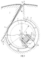
Die in Fig. 1 dargestellte Spannvorrichtung ist im wesentlichen aus einer in einen Plattenzylinder 1 eingebrachten Grube, die einen Einführkanal 2 und einen zur Zylinderachse (nicht dargestellt) parallel verlaufenden zylindrischen Spannkanal 3 aufweist, und einer zum Spannkanal 3 achsparallel angeordneten Spannspindel 4 gebildet. Die wirksame Breite des Einführkanals 2 ist mit dem Bezugszeichen 17 gekennzeichnet. Eine Wand des Einführkanals 2 weist einen kreissegmentförmigen Abschnitt 5 auf, den zugleich ein Kreissegment des Umfangskreises des Spannkanals 3 ist. Die Spannspindel 4 weist einen zylindrischen Spindelkörper 6 und Lagerzapfen 7 auf, wobei die Achse 8 des Spindelkörpers 6 gegenüber der Achse 9 der Lagerzapfen 7 versetzt ist. Die Spannspindel 4 ist im Spannkanal 3 so angeordnet, daß die Achse 9 der Lagerzapfen 7 mit der Achse des Spannkanals 3 identisch ist. Dadurch ergibt sich eine exzentrische Anordnung des Spindelkörpers 6 im Spannkanal 3. In einer Umfangsoberfläche 10 der Spannspindel 4 ist etwa in der Mitte der Spannspindel radial eine Bohrung 11 oder Nut eingebracht, in der ein Abstützelement 12 zum Begrenzen der Durchbiegung der Spannspindel angeordnet ist. Das Abstützelement 12 weist einen Stift 13, eine Mehrzahl von aufeinandergelegten, durch den Stift 13 geführte Federelemente (14) (Tellerfedern) und eine zur Spannspindel 4 achsparallel ausgerichtete Zylinderrolle 15 auf. Die Zylinderrolle 15 wird durch die Federelemente 14 gegen die Wand des Spannkanals 3 gedrückt und wirkt so der Durchbiegung der Spannspindel 4 entgegen. Der Stift 13 begrenzt dabei gleichzeitig die Durchbiegung der Spannspindel 4. Das Abstützelement 12 kann wahlweise auch durch eine Schraubenfeder oder ein anderes elastisches Element und eine direkt auf der Schraubenfeder aufliegende oder in einem auf der Schraubenfeder aufliegenden Rollenkäfig laufende Zylinderrolle oder Kugel gebildet werden. In diesem Falle ergibt sich die Durchbiegungsbegrenzung durch die Länge der vollständig komprimierten Schraubenfeder. Obwohl im vorliegenden Ausführungsbeispiel nur ein einziges Abstützelement erwähnt ist, gilt als selbstverständlich, daß der Fachmann bei der Ausgestaltung einer erfindungsgemäßen Aufspannvorrichtung in Abhängigkeit von der Länge der Spannspindel 4 und den auftretenden Durchbiegekräften und im Hinblick auf einen geringstmöglichen Verschleiß der Zylinderrolle 15 bzw. der Kugel nach eigenem Ermessen festlegt, wieviel Abstützelemente er an der Spannspindel anbringen muß.The clamping device shown in FIG. 1 is essentially formed from a pit introduced into a
Beim Aufspannen einer Druckplatte 16 auf den Plattenzylinder 1 werden das spitzwinklig oder rechtwinklig vorgebogene vordere Ende der Druckplatte 16 und das mit einem stumpfen Winkel vorgebogene hintere Ende der Druckplatte 16 in den Einführkanal 2 hineingesteckt. Dann wird die Spannspindel 4 in an sich bekannter Weise, zum Beispiel mittels eines Schneckengetriebes, so gedreht, daß der Spindelkörper 6 die beiden Enden der Druckplatte 16 erfaßt und gegen den kreissegmentförmigen Abschnitt 5 drückt. Gemäß Fig. 1 wird die Spannspindel 4 also gegen den Uhrzeigersinn gedreht. Bem Drehen der Spannspindel 4 bewirken die Oberflächenrauhigkeit des Spindelkörpers 6 und die Rauhigkeit der beiden Enden der Druckplatte 16 und des kreissegmentförmigen Abschnitts 5, daß die beiden Enden der Druckplatte 16 so weit wie möglich in den Einführkanal 2 hineingezogen und verklemmt werden. Die hierbei erforderliche Oberflächenrauhigkeit des Spindelkörpers 6 kann entweder durch die fertigungsübliche Rauhtiefe oder aber durch einen gesonderten Fertigungsschritt, wie etwa durch Bördeln, sichergestellt sein.When a
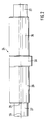
Fig. 2 zeigt in einer schematischen Seitenansicht eine in der Aufspannvorrichtung verwendbare Spannspindel gemäß einer zweiten erfindungsgemäßen Ausführungsform. Auf die Darstellung des Plattenzylinders 1, des Einführkanals 2 und des Spannkanals 3 sowie der Plattenenden der Druckplatte 16 wird der Übersichtlichkeit der Darstellung halber verzichtet, da diese ebenso wie die Anordnung und das Funktionsprinzip der Spannspindel 24 den entsprechenden Merkmalen der Spannspindel 4 aus dem ersten Ausführungsbeispiel entsprechen.2 shows a schematic side view of a clamping spindle that can be used in the clamping device according to a second embodiment of the invention. The illustration of the
Gemäß Fig. 2 weist die Spannspindel 24 einen Spindelkörper 26, Lagerzapfen 27 und einen auf dem Spindelkörper 26 befindlichen Stützabschnitt 30 auf. Die Achse 28 des Spindelkörpers 26 ist gegenüber der Achse 29 der Lagerzapfen 27 versetzt, so daß die Spannspindel 24 wie ein Exzenter wirkt. Der etwa in der Mitte des Spindelkörpers 26 angeordnete Stützabschnitt 30 ist zylinderförmig ausgebildet, wobei seine Drehachse mit der Achse 29 der Lagerzapfen 27 identisch ist und wobei sein Durchmesser so bemessen ist, daß der Stützabschnitt 30 im Spannkanal 3 mit Gleitsitz angeordnet, d.h., im Spannkanal 3 drehbar gelagert ist. Obwohl bereits ein einziger Stützabschnitt 30 eine Durchbiegung der Spannspindel 24 nahezu vollständig verhindert, kann es aufgrund der auftretenden Kräfte vorteilhaft sein, auf der Spannspindel 24 eine Mehrzahl von Stützabschnitten 30 vorzusehen, um den Verschleiß der Stützabschnitte 30 so klein wie möglich zu halten. Dabei kann es dem Fachmann überlassen werden, die Breite der jeweiligen Stützabschnitte 30 in Abhängigkeit von der Anzahl der vorzusehenden Stützabschnitte 30 zu ermitteln.2, the clamping
Beim Aufspannen einer Druckplatte 16 auf den Plattenzylinder 1 wird in dem ersten Ausführungsbeispiel entsprechender Weise die Spannspindel 24 mittels einer an sich bekannten Vorrichtung, wie zum Beispiel einem Schneckengetriebe, derart gedreht, daß der exzentrisch gelagerte Spindelkörper 26 die beiden Enden der Druckplatte 16 erfaßt und so weit wie möglich in den Einführkanal 2 hineinzieht und diese dabei am kreissegmentförmigen Abschnitt 5 des Einführkanals 2 verklemmt. Um dabei die Spannspindel 24 unbegrenzt drehen zu können, d.h. insbesondere, um zu vermeiden, daß der Stützabschnitt 30 mit seinem aus der Oberfläche des Spindelkörpers 26 herausragenden Abschnitt die Enden der Druckplatte 16 verformt oder beschädigt, ist wahlweise eine der beiden folgenden Vorkehrungen zu treffen: Entweder wird in die beiden Enden der Druckplatten 16 jeweils eine Aussparung gestanzt, in die der Stützabschnitt 30 beim Spannen der Druckplatte 16 hineingedreht werden kann, oder der aus der Oberfläche des Spindelkörpers 26 herausragende Abschnitt des Stützabschnitts 30 wird so abgeflacht, daß in den Enden der Druckplatte 16 keine Aussparung erforderlich ist. Bei der Bemessung der Abflachung kann davon ausgegangen werden, daß die Spannspindel 24 beim Spannen und beim Lösen nur etwa um eine Viertelumdrehung in der jeweiligen Richtung gedreht zu werden braucht.When a
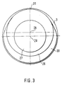
Fig. 3 zeigt in einer schematischen Darstellung eine Stirnansicht der in Fig. 2 dargestellten Spannspindel. Diese Ansicht ist stark schematisiert dargestellt, um insbesondere die Abflachung des Stützabschnitts 30 zu zeigen. Wie aus Fig 3 ersichtlich ist, ist der Stützabschnitt 30 von einer Bezugsstelle 31, an der der Umfangskreis des Stützabschnitts 30 und der Umfangskreis des Spindelkörpers 26 sich berühren, aus nach beiden Richtungen über einen Bereich von jeweils 90° abgeflacht.Fig. 3 shows a schematic representation of an end view of the clamping spindle shown in Fig. 2. This view is shown in a highly schematic manner, in particular to show the flattening of the
Claims (4)
- Device for clamping a flexible printing plate (16) onto the plate cylinder (1) of a rotary printing machine having a groove (2, 3) in the plate cylinder (1) which has an insertion channel (2) and a cylindrical clamping channel (3), in which a clamping spindle (4) is eccentrically rotatably mounted for pressing the ends of the printing plate (16) against a wall of the insertion channel (2) and for clamping the printing plate (16), characterised in that one wall of the groove (2, 3) has an arcuate section (5) which is also a circular segment of the circumferential circle of the clamping channel (3).
- Device according to claim 1, characterised in that the clamping spindle (4) has a support element (12) for limiting its bending which supports the clamping spindle (4) on the wall of the clamping channel (3).
- Device according to claim 1 or 2, characterised in that the clamping spindle (4) has a spindle body (6) and journal pins (7) which are axially parallel to this, and in that the support element (12) is designed as a spring element (14) introduced radially into the spindle body (6) and having a cylindrical roller (15) rolling on the wall of the clamping channel (3).
- Device according to claim 1 or 2, characterised in that the spindle body (26) has a cylindrical support section (30), concentric to the journal pins (27), which is arranged in the clamping channel (3) with sliding fit.
Applications Claiming Priority (2)
| Application Number | Priority Date | Filing Date | Title |
|---|---|---|---|
| DE4005093 | 1990-02-17 | ||
| DE4005093A DE4005093C1 (en) | 1990-02-17 | 1990-02-17 | Forme clamp for printing cylinder - has channel in cylinder with spindle to clamp form eccentrically |
Publications (2)
| Publication Number | Publication Date |
|---|---|
| EP0443350A1 EP0443350A1 (en) | 1991-08-28 |
| EP0443350B1 true EP0443350B1 (en) | 1994-12-21 |
Family
ID=6400437
Family Applications (1)
| Application Number | Title | Priority Date | Filing Date |
|---|---|---|---|
| EP91101248A Expired - Lifetime EP0443350B1 (en) | 1990-02-17 | 1991-01-31 | Device for tensioning a flexible printing plate onto a cylinder of a rotary printing press |
Country Status (5)
| Country | Link |
|---|---|
| US (1) | US5062363A (en) |
| EP (1) | EP0443350B1 (en) |
| JP (1) | JP3001995B2 (en) |
| CA (1) | CA2034427C (en) |
| DE (2) | DE4005093C1 (en) |
Families Citing this family (23)
| Publication number | Priority date | Publication date | Assignee | Title |
|---|---|---|---|---|
| DE4234332A1 (en) * | 1992-10-12 | 1994-04-14 | Heidelberger Druckmasch Ag | Clamping device for attaching a flexible printing form to the outer surface of a cylinder |
| DE4238343C2 (en) * | 1992-11-13 | 2003-03-27 | Kocher & Beck Gmbh & Co Rotati | Cliché fixture |
| DE4401201C2 (en) * | 1994-01-18 | 1996-08-01 | Koenig & Bauer Albert Ag | Device for holding an arcuate support |
| US5485784A (en) * | 1994-06-28 | 1996-01-23 | Walschlaeger, Sr.; Alan R. | Printing plate cylinder with universal lockup apparatus |
| DE19509561C2 (en) * | 1995-03-16 | 1997-10-23 | Koenig & Bauer Albert Ag | Device for clamping plates on a cylinder |
| IT1282385B1 (en) * | 1995-05-05 | 1998-03-20 | Koenig & Bauer Albert Ag | DEVICE FOR FIXING A UNIT OF RUBBERIZED FABRIC ON A CYLINDER OF A ROTARY PRINTING MACHINE |
| DE19521645C2 (en) * | 1995-06-14 | 1998-07-09 | Koenig & Bauer Albert Ag | Device for a slit-shaped holding device |
| DE19524296C2 (en) * | 1995-07-06 | 1997-05-15 | Koenig & Bauer Albert Ag | cylinder |
| FR2737149B1 (en) * | 1995-07-25 | 1997-10-17 | Heidelberg Harris Sa | DEVICE FOR FIXING A PRINTING PLATE ON A PLATE-HOLDING CYLINDER |
| DE19533178C2 (en) * | 1995-09-08 | 1997-06-26 | Koenig & Bauer Albert Ag | cylinder |
| DE29600845U1 (en) * | 1996-01-19 | 1996-03-07 | Roland Man Druckmasch | Device for fastening a covering on a printing unit cylinder |
| DE19606744C2 (en) * | 1996-02-23 | 1998-12-10 | Roland Man Druckmasch | Device for attaching a flexible pressure plate |
| US5735211A (en) * | 1996-06-13 | 1998-04-07 | Mark Andy, Inc. | Clamping and tensioning device for printing plates |
| US5749298A (en) * | 1997-06-10 | 1998-05-12 | Reeves Brothers, Inc. | Arrangement for securing a printing blanket to a cylinder |
| US6131513A (en) * | 1998-10-23 | 2000-10-17 | Heidelberger Druckmaschinen Ag | Printing press with simple lock-up plate cylinder |
| US6378430B1 (en) | 1999-10-15 | 2002-04-30 | King Press Corporation | Cylinder with plate gripping device |
| DE10024331B4 (en) * | 2000-05-17 | 2005-08-18 | Koenig & Bauer Ag | Device for clamping and / or clamping |
| US6739961B2 (en) * | 2001-08-02 | 2004-05-25 | Donald E. Haney | Abrasive band tightening apparatus |
| TWM260360U (en) * | 2004-08-02 | 2005-04-01 | Ruei-Sen Liau | Tightening device for winding emery belt of spindle |
| JP4653981B2 (en) * | 2004-08-10 | 2011-03-16 | 三菱重工印刷紙工機械株式会社 | Printing press blanket cylinder |
| EP2609026B1 (en) * | 2010-08-25 | 2018-08-01 | Hewlett-Packard Development Company, L.P. | Substrate support |
| JP6324076B2 (en) * | 2014-01-10 | 2018-05-16 | 三菱重工機械システム株式会社 | Blanket tightening device, blanket cylinder, printing machine |
| US20220168868A1 (en) * | 2020-12-01 | 2022-06-02 | Fortune Extendables Corp. | Abrasive wheel which can be provided with a sandpaper |
Citations (1)
| Publication number | Priority date | Publication date | Assignee | Title |
|---|---|---|---|---|
| US3276365A (en) * | 1964-04-25 | 1966-10-04 | Roland Offsetmaschf | Printing plate clamping device for a printing press |
Family Cites Families (9)
| Publication number | Priority date | Publication date | Assignee | Title |
|---|---|---|---|---|
| US2279204A (en) * | 1940-12-13 | 1942-04-07 | Meisel Press Mfg Company | Printing cylinder |
| DE1196213B (en) * | 1959-11-12 | 1965-07-08 | American Type Founders Co Inc | Flexible printing plate for mounting on the plate cylinder of a rotary printing press and bending device for producing this printing plate |
| US3234694A (en) * | 1963-11-06 | 1966-02-15 | John F Vosburg | Abrasive strip holding and tightening mechanism |
| DE1561005A1 (en) * | 1966-10-01 | 1970-04-16 | Maschf Augsburg Nuernberg Ag | Device for clamping flexible printing plates on the forme cylinder of rotary printing machines |
| FR2478538A1 (en) * | 1980-03-21 | 1981-09-25 | Creusot Loire | DEVICE FOR CORRECTING THE POSITION OF A PLATE CARRIED BY A CYLINDER OF A PRINTING MACHINE |
| US4495865A (en) * | 1983-03-15 | 1985-01-29 | Komori Printing Machinery Co., Ltd. | Plate clamping device of web-fed rotary printing press |
| DE3326215C2 (en) * | 1983-07-21 | 1986-04-03 | M.A.N.- Roland Druckmaschinen AG, 6050 Offenbach | Device for clamping a printing plate or a rubber blanket |
| DE3339185C2 (en) * | 1983-10-28 | 1986-01-30 | M.A.N.- Roland Druckmaschinen AG, 6050 Offenbach | Device for clamping plates on a forme cylinder of a rotary printing press |
| DE3884939T3 (en) * | 1988-02-29 | 2000-12-28 | Goss Graphic Syst Inc | Tension-free plate lock. |
-
1990
- 1990-02-17 DE DE4005093A patent/DE4005093C1/en not_active Expired - Lifetime
-
1991
- 1991-01-14 US US07/640,688 patent/US5062363A/en not_active Expired - Fee Related
- 1991-01-17 CA CA002034427A patent/CA2034427C/en not_active Expired - Fee Related
- 1991-01-31 EP EP91101248A patent/EP0443350B1/en not_active Expired - Lifetime
- 1991-01-31 DE DE59103943T patent/DE59103943D1/en not_active Expired - Fee Related
- 1991-02-15 JP JP3022121A patent/JP3001995B2/en not_active Expired - Lifetime
Patent Citations (1)
| Publication number | Priority date | Publication date | Assignee | Title |
|---|---|---|---|---|
| US3276365A (en) * | 1964-04-25 | 1966-10-04 | Roland Offsetmaschf | Printing plate clamping device for a printing press |
Also Published As
| Publication number | Publication date |
|---|---|
| DE59103943D1 (en) | 1995-02-02 |
| CA2034427A1 (en) | 1993-08-17 |
| JPH058375A (en) | 1993-01-19 |
| JP3001995B2 (en) | 2000-01-24 |
| DE4005093C1 (en) | 1991-06-20 |
| CA2034427C (en) | 1993-08-17 |
| EP0443350A1 (en) | 1991-08-28 |
| US5062363A (en) | 1991-11-05 |
Similar Documents
| Publication | Publication Date | Title |
|---|---|---|
| EP0443350B1 (en) | Device for tensioning a flexible printing plate onto a cylinder of a rotary printing press | |
| DE1228627B (en) | Device for fastening a flexible printing plate on the forme cylinder of a rotary printing press | |
| DE3009716C2 (en) | Securing element for a screw nut that can be placed on a threaded bolt | |
| CH690426A5 (en) | Device for clamping plates on a cylinder. | |
| DE60108025T2 (en) | Winding core centering bushing for a roll of strip material | |
| EP0451574B1 (en) | Device to tension plates onto a form cylinder of a rotary printing machine | |
| WO2000073067A2 (en) | Method and devices for fastening a flexible plate | |
| DE19541249B4 (en) | Blanket cylinder for rotary printing machine - has pivotable spindle supporting pressure noses turning, together with spindle, so that they act radially outwards to press bent-off legs against one wall of slot | |
| DE19757895C2 (en) | Side register adjustment device for printing plates | |
| DE3812137A1 (en) | DEVICE FOR FASTENING A FLEXIBLE PRINT PLATE | |
| EP1545881A1 (en) | Clamping device for clamping a flexible covering on a cylinder of a printing machine | |
| DE10241284B3 (en) | Clamping device for fixing a plate, especially a printing plate, on the periphery of a cylinder comprises a first clamping element, a pivotably mounted second clamping element | |
| DD290627A5 (en) | DEVICE FOR FIXING A BENDING PRESSURE PLATE | |
| DE202021104272U1 (en) | Spring tensioner | |
| DE4300099C1 (en) | Clamping device with parallel clamping surfaces | |
| DD261770A1 (en) | DEVICE FOR FIXING A BENDING PRESSURE PLATE | |
| DE3339185C2 (en) | Device for clamping plates on a forme cylinder of a rotary printing press | |
| DD261764A1 (en) | DEVICE FOR FIXING A BENDING PRESSURE PLATE | |
| DE60027518T2 (en) | Device for mounting a blanket of a printing machine | |
| DE1489325B1 (en) | Lamp holder for a fluorescent tube | |
| DE10060171C1 (en) | Sleeve retainer for printing cylinder has sprung detent to engage ridge formed on flange at end of the sleeve panel | |
| DE19509562C1 (en) | Device for releasing plates from a cylinder | |
| DD261765A1 (en) | DEVICE FOR FIXING A BENDING PRESSURE PLATE | |
| DD261768A1 (en) | DEVICE FOR FIXING A BENDING PRESSURE PLATE | |
| DE2328910C3 (en) | Screw drive |
Legal Events
| Date | Code | Title | Description |
|---|---|---|---|
| PUAI | Public reference made under article 153(3) epc to a published international application that has entered the european phase |
Free format text: ORIGINAL CODE: 0009012 |
|
| AK | Designated contracting states |
Kind code of ref document: A1 Designated state(s): CH DE FR GB IT LI |
|
| 17P | Request for examination filed |
Effective date: 19910801 |
|
| 17Q | First examination report despatched |
Effective date: 19930726 |
|
| ITF | It: translation for a ep patent filed |
Owner name: BARZANO' E ZANARDO ROMA S.P.A. |
|
| GRAA | (expected) grant |
Free format text: ORIGINAL CODE: 0009210 |
|
| AK | Designated contracting states |
Kind code of ref document: B1 Designated state(s): CH DE FR GB IT LI |
|
| REF | Corresponds to: |
Ref document number: 59103943 Country of ref document: DE Date of ref document: 19950202 |
|
| GBT | Gb: translation of ep patent filed (gb section 77(6)(a)/1977) |
Effective date: 19950315 |
|
| ET | Fr: translation filed | ||
| PLBE | No opposition filed within time limit |
Free format text: ORIGINAL CODE: 0009261 |
|
| STAA | Information on the status of an ep patent application or granted ep patent |
Free format text: STATUS: NO OPPOSITION FILED WITHIN TIME LIMIT |
|
| 26N | No opposition filed | ||
| PGFP | Annual fee paid to national office [announced via postgrant information from national office to epo] |
Ref country code: GB Payment date: 19991213 Year of fee payment: 10 |
|
| PGFP | Annual fee paid to national office [announced via postgrant information from national office to epo] |
Ref country code: DE Payment date: 19991217 Year of fee payment: 10 Ref country code: CH Payment date: 19991217 Year of fee payment: 10 |
|
| PGFP | Annual fee paid to national office [announced via postgrant information from national office to epo] |
Ref country code: FR Payment date: 19991221 Year of fee payment: 10 |
|
| PG25 | Lapsed in a contracting state [announced via postgrant information from national office to epo] |
Ref country code: LI Free format text: LAPSE BECAUSE OF NON-PAYMENT OF DUE FEES Effective date: 20010131 Ref country code: GB Free format text: LAPSE BECAUSE OF NON-PAYMENT OF DUE FEES Effective date: 20010131 Ref country code: CH Free format text: LAPSE BECAUSE OF NON-PAYMENT OF DUE FEES Effective date: 20010131 |
|
| REG | Reference to a national code |
Ref country code: CH Ref legal event code: PL |
|
| GBPC | Gb: european patent ceased through non-payment of renewal fee |
Effective date: 20010131 |
|
| PG25 | Lapsed in a contracting state [announced via postgrant information from national office to epo] |
Ref country code: FR Free format text: LAPSE BECAUSE OF NON-PAYMENT OF DUE FEES Effective date: 20010928 |
|
| PG25 | Lapsed in a contracting state [announced via postgrant information from national office to epo] |
Ref country code: DE Free format text: LAPSE BECAUSE OF NON-PAYMENT OF DUE FEES Effective date: 20011101 |
|
| REG | Reference to a national code |
Ref country code: FR Ref legal event code: ST |
|
| PG25 | Lapsed in a contracting state [announced via postgrant information from national office to epo] |
Ref country code: IT Free format text: LAPSE BECAUSE OF NON-PAYMENT OF DUE FEES;WARNING: LAPSES OF ITALIAN PATENTS WITH EFFECTIVE DATE BEFORE 2007 MAY HAVE OCCURRED AT ANY TIME BEFORE 2007. THE CORRECT EFFECTIVE DATE MAY BE DIFFERENT FROM THE ONE RECORDED. Effective date: 20050131 |