EP0443329A2 - Four de cuisson - Google Patents
Four de cuisson Download PDFInfo
- Publication number
- EP0443329A2 EP0443329A2 EP91100677A EP91100677A EP0443329A2 EP 0443329 A2 EP0443329 A2 EP 0443329A2 EP 91100677 A EP91100677 A EP 91100677A EP 91100677 A EP91100677 A EP 91100677A EP 0443329 A2 EP0443329 A2 EP 0443329A2
- Authority
- EP
- European Patent Office
- Prior art keywords
- guide
- link
- baking oven
- spring
- oven door
- Prior art date
- Legal status (The legal status is an assumption and is not a legal conclusion. Google has not performed a legal analysis and makes no representation as to the accuracy of the status listed.)
- Granted
Links
- 230000000750 progressive effect Effects 0.000 claims description 2
- 238000006073 displacement reaction Methods 0.000 abstract description 4
- 235000013305 food Nutrition 0.000 description 4
- 230000002401 inhibitory effect Effects 0.000 description 4
- 238000000034 method Methods 0.000 description 3
- 230000000694 effects Effects 0.000 description 2
- 230000003068 static effect Effects 0.000 description 2
- 238000004140 cleaning Methods 0.000 description 1
- 230000005574 cross-species transmission Effects 0.000 description 1
- 238000010438 heat treatment Methods 0.000 description 1
- 235000021056 liquid food Nutrition 0.000 description 1
Images


Classifications
-
- F—MECHANICAL ENGINEERING; LIGHTING; HEATING; WEAPONS; BLASTING
- F24—HEATING; RANGES; VENTILATING
- F24C—DOMESTIC STOVES OR RANGES ; DETAILS OF DOMESTIC STOVES OR RANGES, OF GENERAL APPLICATION
- F24C15/00—Details
- F24C15/16—Shelves, racks or trays inside ovens; Supports therefor
- F24C15/162—Co-operating with a door, e.g. operated by the door
Definitions
- the invention relates to an oven according to the preamble of claim 1.
- a spring catch device in which, in the closed position of a drawer-like horizontally displaceable oven door at the end of the sliding path of the push pulls firmly connected to the oven door, a roller connected to a push-pull runs onto a spring-loaded latching roller and after resilient deflection of this locking roller locked behind the same, with the result that the oven door rests with a certain closing force on the muffle flange of the oven muffle.
- the spring catch device causes braking over a relatively short path of approximately 1.5 cm the oven door moving into the closed position and locking the same.
- the invention has for its object to avoid the above disadvantages and to enable a soft but safe closing and opening movement of the oven door.
- a link guide with a support element makes it possible, in particular, to set the start of the inhibiting or braking forces acting on the oven door or its push pulls, as well as the inhibiting or braking forces themselves, so that these forces act clearly before the oven door is in the closed position begin and a smooth, smooth closing movement is guaranteed. Esp. it is possible that if the oven door is not completely closed, it rolls back into the position in which the aforementioned forces begin to act on the oven door, so that the incomplete closing process can be clearly recognized. The same goes for opening the oven door, of course.
- the link guide can be designed in such a way that in order to open the oven door, continuously increasing inhibiting forces have to be overcome in favor of a smooth and jerk-free movement of the oven door.
- the invention is advantageously applicable to ovens of all types, regardless of the heating and of course also for microwave ovens.
- the oven is part of a so-called standing oven 1, which has an oven muffle 2 in the interior of the oven housing, which is open towards the front and is delimited there by an oven flange 2 '.
- a switch panel 3 with, for example, electrical control elements 4 on the front of the stove.
- 6 is a so-called baking cart, consisting of a vertically standing and drawer-like sliding oven door 7, which has a handle 8 and hook-like holding elements 9 on the inside of the door for it has hookable food support 10.
- each push train 11 has a roller 13, while a support roller 14 is arranged in a stationary manner on each sliding track 12.
- a spring catch device consisting of a link guide, generally designated 15, in the form of a closing spring, which will be described below, and a support element in the form of a pair of rollers 16.
- the link guide 15 is arranged in a stationary manner in the sliding track 12, while the rollers 16 are fastened to at least one push pull 11 of the oven door 7.
- the rollers 16 run onto the slotted parts 17 which open slightly and in the direction of the push-pull 11, and these brake the oven 6 with continuously increasing braking force until a maximum braking force has been overcome and the rollers 16 - as explained below - engage in a locking position in which the oven door 7 is pressed onto the muffle flange 2 'with a predetermined force.
- Fig. 2 shows a slightly different geometric arrangement of the spring catch device.
- the figure shows the lower part of the oven muffle 2 with the food container 18 and underneath the rear part of a push-pull 11, which is essentially designed as a hollow profile and has the roller 13 at the end.
- a support element 20, on which the rollers 16 are rotatably mounted, is fastened to the lower limit 19 of the push-pull 11 which can be displaced in the direction of the arrow.
- the link guide is arranged, the two link parts 17 being mounted on a pivot axis 21 fixed to the housing in a scissor-like manner and already being connected to the rollers 16 in the position shown.
- the two link parts 17 are pressed against one another in the direction of the rollers 16 by means of at least one spring 22.
- the link guide is pivoted by 90 ° with respect to the arrangement of the link guide according to FIG. 1.
- FIG. 3 shows a spring catch device as a detail in plan view, only the parts essential for understanding the invention being shown.
- the two identical parts of the link 17a which are arranged in mirror image to one another, are designed as two-armed levers and are pivotably mounted about individually assigned pivot axes 21.
- the longer lever arm of each link part 17a has two guide sections 23 and 24 which are inclined towards one another on both sides of a reversal point 25.
- the guide sections 23 of both link parts 17a initially run with a flat opening angle a and then essentially parallel to the reversal point 25, after which the guide section 24 is at a substantially steeper angle to the horizontal runs.
- the link parts 17a are suspended on springs 22 which press these lever arms in the direction of the arrow and the lever arms having the guide sections. 4, of course, there is also the possibility to arrange a single spring 22 between the shorter lever arms, whereby the same effect is achieved.
- the two freely rotatable rollers 16 run onto the guide sections 23 assigned to them, as a result of which the displacement movement is gently inhibited. This accretion takes place relatively early, namely when the oven door 7 (FIG. 1) is still a relatively large distance of approximately 80 mm from the muffle flange 2 '.
- the two again identical link parts 17b are provided with bearing projections 26 and are pivotably mounted on a common pivot axis 21.
- the guide sections 23 in the rest position of the link guide are inclined towards one another towards the front, so that the rollers 16, not shown, are moved back into the starting position before the link parts 17b are reached if the baking cart 6 is inadvertently not completely in the Locked or closed position is moved.
- the shorter lever arms are attached to corresponding springs.
- the two link parts 17c are each S-shaped as single-armed levers and have a common pivot axis 21.
- the link parts 17c are pressed against one another by a spring 22.
- the two link parts overlap in the area of their reversal points 25.
- Both guide sections 23 and 24 on both sides of the reversal points 25 are designed very flat, so that the rollers 16 after passing over the reversal points 25 very gently along the flat-inclined guide sections 24 in the Closed positions.
- the link parts 17d are arranged rigidly on the housing, the guide sections 23 again striving flatly towards the front of the oven and the guide sections 24 are inclined somewhat more steeply to the horizontal.
- the two rollers 16 of the pair of rollers are resiliently displaceable relative to one another, for example by are easily rotatably mounted on lever arms 39, which lever arms 39 are mounted on a common pivot axis 27.
- a spring 22 pushes the two lever arms 39 and thus also the rollers 16 apart in the direction of their associated guide sections 23, 24 by the distance b.
- the part of the link guide which is fixed to the housing is formed by a one-piece, two-legged closing spring 28, as is indicated in FIG. 1.
- This closing spring 28 is fastened to the housing by means of fastening elements 30 on the round spring part 29.
- the link parts 17 are pressed resiliently against one another (dashed position) and are moved apart against spring force when the rollers arranged at a fixed distance from one another move until the rollers have overcome the reversal points 25 and the rollers in the region of the guide sections 24 on the spring part 29 get into the closed position.
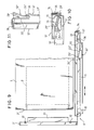
- FIG. 9 again shows an oven muffle 2 with an oven flange 2 ′, which is installed in an oven housing 1.
- the oven door 7 ' is also part of a so-called baking cart 6' which can be moved like a drawer.
- the oven shown in FIG. 9 should have a microwave device of a type known per se;
- a so-called microwave trap in the form of a microwave shield 31 is arranged on the inside of the oven door 7 ', which plunges into the interior of the oven muffle 2 when the oven door 7' is closed.
- a circumferential microwave door seal 32 is arranged on the inside of the door, which lies tightly against the oven flange 2 'in the closed position.
- a fixed component of the baking cart 6 ' are rigidly connected to the oven door 7', horizontal sliding cables 11 ', which are mounted with rollers 13 in horizontal but also stationary tracks or tracks 12' so as to be displaceable in the direction of the arrow.
- rollers 13 ' are also arranged on the running rails 12', so that when the baking trolley 6 'is moved, the sliding trains 11' are supported on the last-mentioned running rollers 13 and the sliding trains 11 'in turn are supported with the running rollers 13 on the running rails 12'.
- a link guide which is fixedly arranged on at least one push-pull 11' and has two guide sections 23 'and 24' which are inclined to the horizontal and are V-shaped with respect to one another, the guide section 23 'relative to the other guide section 24 'is somewhat longer and has a smaller angle of inclination with respect to the horizontal.
- the running rail 12 ' has at the end a detent spring 33 which is hooked and fastened to the vertical end 35 of the running rail 12' at the rear end of the running rail 12 'by means of the U-shaped spring end 34 and which has a freely rotatable locking roller 36 at the free spring end having.
- the detent spring preferably has a progressive spring characteristic, ie the force required to bend the detent spring out of the rest position is initially low and then increases continuously.
- the detent roller 36 of the detent spring 33 When the baking trolley 6 'is moved into the door-closed position, the detent roller 36 of the detent spring 33 initially runs smoothly onto the guide track 23' of the link guide 15 ', a more or less continuous increase in the closing actuating force being achieved depending on the slope of the guide section 23'.
- the reversing guide surface 25 'between the two guide sections 23' and 24 ' e.g. in the form of a gentle curve or a short straight line, this can be followed by a stationary displacement phase with constant closing actuation force.
- the phases are reversed, i.e. After a brief sliding action of the locking roller 36 along the guide section 24 ', after overcoming the reversing surface 25', the baking cart 6 'undergoes an automatic, gentle sliding movement until the locking roller 36 separates from the guide section 23'.
- the detent spring 33 executes a vertical lifting movement during the closing and opening movement of the oven door 7 '
- the detent spring 33' and the link guide 15 '' are pivoted by 90 °, so that the detent spring 33 ' executes a horizontal lifting movement.
- the link guide 15 '' is formed here by a bend 37 by 90 ° at the end of the push pull 11 '', this bend 37 in turn forming guide sections 23 'and 24' on which the locking roller 36 'during the sliding movement of the baking cart 6' Latch spring 33 'slides in the manner described above.
- This detent spring 33 ' is attached to a bent extension 38 of the running rail 12 ', for example welded on.
- the link guide and the detent spring can be arranged at any point in the area of the sliding path of the baking trolley, e.g. from outside of this sliding track.
- the closing actuating force can also be set as desired, e.g. by changing the spring force of the detent spring or the angular inclination of the guide sections.
- the guide arrangement automatically compensates for tolerances in the positions of the oven door and oven flange that are subject to tolerance, i.e. sufficient closing force is ensured in any case when the oven door is closed. Last but not least, you get a low-jerk locking mechanism regardless of the static load on the baking cart.
Landscapes
- Engineering & Computer Science (AREA)
- Chemical & Material Sciences (AREA)
- Combustion & Propulsion (AREA)
- Mechanical Engineering (AREA)
- General Engineering & Computer Science (AREA)
- Furnace Housings, Linings, Walls, And Ceilings (AREA)
- Baking, Grill, Roasting (AREA)
- Electric Ovens (AREA)
Priority Applications (1)
| Application Number | Priority Date | Filing Date | Title |
|---|---|---|---|
| AT91100677T ATE96533T1 (de) | 1990-02-21 | 1991-01-21 | Backofen. |
Applications Claiming Priority (4)
| Application Number | Priority Date | Filing Date | Title |
|---|---|---|---|
| DE4005477 | 1990-02-21 | ||
| DE4005477 | 1990-02-21 | ||
| DE4023949 | 1990-07-27 | ||
| DE4023949A DE4023949A1 (de) | 1990-02-21 | 1990-07-27 | Backofen |
Publications (3)
| Publication Number | Publication Date |
|---|---|
| EP0443329A2 true EP0443329A2 (fr) | 1991-08-28 |
| EP0443329A3 EP0443329A3 (en) | 1992-03-25 |
| EP0443329B1 EP0443329B1 (fr) | 1993-10-27 |
Family
ID=25890385
Family Applications (1)
| Application Number | Title | Priority Date | Filing Date |
|---|---|---|---|
| EP91100677A Expired - Lifetime EP0443329B1 (fr) | 1990-02-21 | 1991-01-21 | Four de cuisson |
Country Status (3)
| Country | Link |
|---|---|
| EP (1) | EP0443329B1 (fr) |
| DE (2) | DE4023949A1 (fr) |
| ES (1) | ES2045959T3 (fr) |
Cited By (13)
| Publication number | Priority date | Publication date | Assignee | Title |
|---|---|---|---|---|
| EP0794389A1 (fr) * | 1996-03-08 | 1997-09-10 | Bosch-Siemens HausgerÀ¤te GmbH | Chariot de four rotatif |
| EP1258685A1 (fr) * | 2001-05-18 | 2002-11-20 | BSH Bosch und Siemens Hausgeräte GmbH | Appareil ménager, en particulier four de cuisson |
| EP1258686A1 (fr) * | 2001-05-18 | 2002-11-20 | BSH Bosch und Siemens Hausgeräte GmbH | Appareil ménager, en particulier four de cuisson |
| DE19738458C2 (de) * | 1997-09-03 | 2003-10-16 | Aeg Hausgeraete Gmbh | Vorrichtung zum Zuhalten einer axial verschiebbaren Ofenmuffeltür |
| US7188619B2 (en) * | 2002-12-19 | 2007-03-13 | Miele & Cie. Kg | Household food warmer |
| EP2093499A1 (fr) | 2008-02-22 | 2009-08-26 | Electrolux Home Products Corporation N.V. | Four de cuisson avec guide rapide |
| EP2093498A1 (fr) * | 2008-02-21 | 2009-08-26 | Electrolux Home Products Corporation N.V. | Four de cuisson |
| DE202009001961U1 (de) | 2009-03-11 | 2010-07-29 | Paul Hettich Gmbh & Co. Kg | Auszugsvorrichtung |
| EP1537365B2 (fr) † | 2002-08-30 | 2016-02-24 | BSH Hausgeräte GmbH | Four a systeme sortant lineaire |
| US10448786B2 (en) | 2013-08-26 | 2019-10-22 | Koninklijke Philips N.V. | Apparatus for preparing food having a drawer with a sliding mechanism |
| CN111850282A (zh) * | 2020-07-23 | 2020-10-30 | 艾亦特工业炉(太仓)有限公司 | 一种水平筒形炉 |
| CN113647842A (zh) * | 2021-08-17 | 2021-11-16 | 东莞市海新金属科技有限公司 | 一种适用于压型内胆的双层拉出滑轨烤架结构 |
| US12035845B1 (en) | 2023-04-26 | 2024-07-16 | Sharkninja Operating Llc | Systems and methods for cooking pizza |
Families Citing this family (10)
| Publication number | Priority date | Publication date | Assignee | Title |
|---|---|---|---|---|
| DE19651225C2 (de) * | 1996-12-10 | 1999-02-18 | Wiesheu Gmbh | Ofen zur Wärmebehandlung von Lebensmitteln |
| DE19828640A1 (de) * | 1998-06-26 | 1999-12-30 | Bsh Bosch Siemens Hausgeraete | Backofen mit eigenbeheiztem Gargutträger |
| DE10203957A1 (de) * | 2002-02-01 | 2003-08-14 | Bsh Bosch Siemens Hausgeraete | Haushaltsgerät, insbesondere Backofen |
| DE10241683A1 (de) * | 2002-09-09 | 2004-03-18 | BSH Bosch und Siemens Hausgeräte GmbH | Schienen- und Teleskopauszug |
| DE10253156A1 (de) | 2002-11-14 | 2004-05-27 | BSH Bosch und Siemens Hausgeräte GmbH | Backofen |
| DE10253157B4 (de) * | 2002-11-14 | 2017-06-22 | BSH Hausgeräte GmbH | Backofen |
| DE10253158B4 (de) * | 2002-11-14 | 2008-01-24 | BSH Bosch und Siemens Hausgeräte GmbH | Backofen |
| DE102005014421A1 (de) * | 2005-03-24 | 2006-10-05 | Electrolux Home Products Corporation N.V. | Auszugssystem für einen Garofen |
| DE202018106399U1 (de) * | 2018-11-12 | 2020-02-13 | Grass Gmbh | Führungsvorrichtung zur Führung eines Gutträgers in einem Gehäuse |
| US11286698B2 (en) | 2019-06-27 | 2022-03-29 | Bsh Home Appliances Corporation | Cooking appliance having a load-bearing door |
Citations (3)
| Publication number | Priority date | Publication date | Assignee | Title |
|---|---|---|---|---|
| DE2036885A1 (de) * | 1970-07-24 | 1972-02-03 | Siemens Elektrogeraete Gmbh | Back- und Bratrohr |
| DE2036889A1 (de) * | 1970-07-24 | 1972-02-03 | Siemens Elektrogeraete Gmbh | Back- und Bratrohr |
| DE8030718U1 (de) * | 1980-11-17 | 1981-03-12 | Bosch-Siemens Hausgeräte GmbH, 7000 Stuttgart | Backofen |
-
1990
- 1990-07-27 DE DE4023949A patent/DE4023949A1/de not_active Withdrawn
-
1991
- 1991-01-21 DE DE91100677T patent/DE59100511D1/de not_active Expired - Fee Related
- 1991-01-21 ES ES91100677T patent/ES2045959T3/es not_active Expired - Lifetime
- 1991-01-21 EP EP91100677A patent/EP0443329B1/fr not_active Expired - Lifetime
Patent Citations (3)
| Publication number | Priority date | Publication date | Assignee | Title |
|---|---|---|---|---|
| DE2036885A1 (de) * | 1970-07-24 | 1972-02-03 | Siemens Elektrogeraete Gmbh | Back- und Bratrohr |
| DE2036889A1 (de) * | 1970-07-24 | 1972-02-03 | Siemens Elektrogeraete Gmbh | Back- und Bratrohr |
| DE8030718U1 (de) * | 1980-11-17 | 1981-03-12 | Bosch-Siemens Hausgeräte GmbH, 7000 Stuttgart | Backofen |
Cited By (15)
| Publication number | Priority date | Publication date | Assignee | Title |
|---|---|---|---|---|
| EP0794389A1 (fr) * | 1996-03-08 | 1997-09-10 | Bosch-Siemens HausgerÀ¤te GmbH | Chariot de four rotatif |
| DE19738458C2 (de) * | 1997-09-03 | 2003-10-16 | Aeg Hausgeraete Gmbh | Vorrichtung zum Zuhalten einer axial verschiebbaren Ofenmuffeltür |
| EP1258685A1 (fr) * | 2001-05-18 | 2002-11-20 | BSH Bosch und Siemens Hausgeräte GmbH | Appareil ménager, en particulier four de cuisson |
| EP1258686A1 (fr) * | 2001-05-18 | 2002-11-20 | BSH Bosch und Siemens Hausgeräte GmbH | Appareil ménager, en particulier four de cuisson |
| EP1537365B2 (fr) † | 2002-08-30 | 2016-02-24 | BSH Hausgeräte GmbH | Four a systeme sortant lineaire |
| US7188619B2 (en) * | 2002-12-19 | 2007-03-13 | Miele & Cie. Kg | Household food warmer |
| EP2093498A1 (fr) * | 2008-02-21 | 2009-08-26 | Electrolux Home Products Corporation N.V. | Four de cuisson |
| EP2093499A1 (fr) | 2008-02-22 | 2009-08-26 | Electrolux Home Products Corporation N.V. | Four de cuisson avec guide rapide |
| DE202009001961U1 (de) | 2009-03-11 | 2010-07-29 | Paul Hettich Gmbh & Co. Kg | Auszugsvorrichtung |
| WO2010102949A1 (fr) * | 2009-03-11 | 2010-09-16 | Paul Hettich Gmbh & Co. Kg | Dispositif d'extraction |
| US9010314B2 (en) | 2009-03-11 | 2015-04-21 | Paul Hettich Gmbh & Co. Kg | Pull-out device |
| US10448786B2 (en) | 2013-08-26 | 2019-10-22 | Koninklijke Philips N.V. | Apparatus for preparing food having a drawer with a sliding mechanism |
| CN111850282A (zh) * | 2020-07-23 | 2020-10-30 | 艾亦特工业炉(太仓)有限公司 | 一种水平筒形炉 |
| CN113647842A (zh) * | 2021-08-17 | 2021-11-16 | 东莞市海新金属科技有限公司 | 一种适用于压型内胆的双层拉出滑轨烤架结构 |
| US12035845B1 (en) | 2023-04-26 | 2024-07-16 | Sharkninja Operating Llc | Systems and methods for cooking pizza |
Also Published As
| Publication number | Publication date |
|---|---|
| DE59100511D1 (de) | 1993-12-02 |
| EP0443329A3 (en) | 1992-03-25 |
| ES2045959T3 (es) | 1994-01-16 |
| DE4023949A1 (de) | 1991-08-22 |
| EP0443329B1 (fr) | 1993-10-27 |
Similar Documents
| Publication | Publication Date | Title |
|---|---|---|
| EP0443329B1 (fr) | Four de cuisson | |
| DE4124512C2 (de) | Schließvorrichtung für Schubladen | |
| EP2760315B1 (fr) | Raccord | |
| EP0717684B1 (fr) | Dispositif permettant de guider une plaque de toit ouvrant de vehicule | |
| DE2941126A1 (de) | Zum schutz eines maschinenbettes bestimmte abdeckung | |
| DE202007007450U1 (de) | Einzugsdämpfung für Schienensystem | |
| DE4227585A1 (de) | Geschirrspülmaschine mit höhenverstellbarem Geschirrkorb | |
| EP2354732A2 (fr) | Porte d'un appareil de réfrigération et/ou de congélation | |
| EP0451737B1 (fr) | Ferrure d'articulation pour meuble d'angle | |
| DE102017211203A1 (de) | Hebesystem für eine Haushaltsgeschirrspülmaschine oder ein Möbel | |
| DE4424002A1 (de) | Wertstoffsammler | |
| DE10253156A1 (de) | Backofen | |
| EP0948674A1 (fr) | Dispositif pour enrouler des bandes textiles | |
| DE10253157B4 (de) | Backofen | |
| DE10253158B4 (de) | Backofen | |
| DE3230228C1 (de) | Ladentheke | |
| DE10105847B4 (de) | Mitnahmevorrichtung für ausziehbaren Möbelboden | |
| DE8515431U1 (de) | Backofen | |
| EP2904939A1 (fr) | Dispositif destiné au guidage d'un élément de poussée et meuble doté d'un tel dispositif | |
| DE4223608A1 (de) | Back- und Bratofen | |
| EP0523424B1 (fr) | Dispositif de guidage pour tiroir | |
| EP2732113B1 (fr) | Fermoir permettant de fermer une porte, plus particulièrement une porte d'appareil | |
| AT385314B (de) | Vorrichtung zum verbinden eines seitlich gefuehrten garagenkipptores mit dem mitnehmer eines torantriebes | |
| CH685167A5 (de) | Schrank mit beidseitig ausziehbarer Lade. | |
| DE10203957A1 (de) | Haushaltsgerät, insbesondere Backofen |
Legal Events
| Date | Code | Title | Description |
|---|---|---|---|
| PUAI | Public reference made under article 153(3) epc to a published international application that has entered the european phase |
Free format text: ORIGINAL CODE: 0009012 |
|
| AK | Designated contracting states |
Kind code of ref document: A2 Designated state(s): AT DE ES FR GB IT NL |
|
| PUAL | Search report despatched |
Free format text: ORIGINAL CODE: 0009013 |
|
| AK | Designated contracting states |
Kind code of ref document: A3 Designated state(s): AT DE ES FR GB IT NL |
|
| 17P | Request for examination filed |
Effective date: 19920918 |
|
| 17Q | First examination report despatched |
Effective date: 19921208 |
|
| GRAA | (expected) grant |
Free format text: ORIGINAL CODE: 0009210 |
|
| AK | Designated contracting states |
Kind code of ref document: B1 Designated state(s): AT DE ES FR GB IT NL |
|
| REF | Corresponds to: |
Ref document number: 96533 Country of ref document: AT Date of ref document: 19931115 Kind code of ref document: T |
|
| GBT | Gb: translation of ep patent filed (gb section 77(6)(a)/1977) |
Effective date: 19931103 |
|
| REF | Corresponds to: |
Ref document number: 59100511 Country of ref document: DE Date of ref document: 19931202 |
|
| REG | Reference to a national code |
Ref country code: ES Ref legal event code: FG2A Ref document number: 2045959 Country of ref document: ES Kind code of ref document: T3 |
|
| ITF | It: translation for a ep patent filed | ||
| ET | Fr: translation filed | ||
| PLBE | No opposition filed within time limit |
Free format text: ORIGINAL CODE: 0009261 |
|
| STAA | Information on the status of an ep patent application or granted ep patent |
Free format text: STATUS: NO OPPOSITION FILED WITHIN TIME LIMIT |
|
| 26N | No opposition filed | ||
| PGFP | Annual fee paid to national office [announced via postgrant information from national office to epo] |
Ref country code: NL Payment date: 20000131 Year of fee payment: 10 |
|
| PG25 | Lapsed in a contracting state [announced via postgrant information from national office to epo] |
Ref country code: NL Free format text: LAPSE BECAUSE OF NON-PAYMENT OF DUE FEES Effective date: 20010801 |
|
| NLV4 | Nl: lapsed or anulled due to non-payment of the annual fee |
Effective date: 20010801 |
|
| REG | Reference to a national code |
Ref country code: GB Ref legal event code: IF02 |
|
| PGFP | Annual fee paid to national office [announced via postgrant information from national office to epo] |
Ref country code: AT Payment date: 20020124 Year of fee payment: 12 |
|
| PGFP | Annual fee paid to national office [announced via postgrant information from national office to epo] |
Ref country code: DE Payment date: 20021217 Year of fee payment: 13 |
|
| PGFP | Annual fee paid to national office [announced via postgrant information from national office to epo] |
Ref country code: GB Payment date: 20030113 Year of fee payment: 13 |
|
| PGFP | Annual fee paid to national office [announced via postgrant information from national office to epo] |
Ref country code: FR Payment date: 20030117 Year of fee payment: 13 |
|
| PG25 | Lapsed in a contracting state [announced via postgrant information from national office to epo] |
Ref country code: AT Free format text: LAPSE BECAUSE OF NON-PAYMENT OF DUE FEES Effective date: 20030121 |
|
| PGFP | Annual fee paid to national office [announced via postgrant information from national office to epo] |
Ref country code: ES Payment date: 20030123 Year of fee payment: 13 |
|
| PG25 | Lapsed in a contracting state [announced via postgrant information from national office to epo] |
Ref country code: GB Free format text: LAPSE BECAUSE OF NON-PAYMENT OF DUE FEES Effective date: 20040121 |
|
| PG25 | Lapsed in a contracting state [announced via postgrant information from national office to epo] |
Ref country code: ES Free format text: LAPSE BECAUSE OF NON-PAYMENT OF DUE FEES Effective date: 20040122 |
|
| PG25 | Lapsed in a contracting state [announced via postgrant information from national office to epo] |
Ref country code: DE Free format text: LAPSE BECAUSE OF NON-PAYMENT OF DUE FEES Effective date: 20040803 |
|
| GBPC | Gb: european patent ceased through non-payment of renewal fee |
Effective date: 20040121 |
|
| PG25 | Lapsed in a contracting state [announced via postgrant information from national office to epo] |
Ref country code: FR Free format text: LAPSE BECAUSE OF NON-PAYMENT OF DUE FEES Effective date: 20040930 |
|
| REG | Reference to a national code |
Ref country code: FR Ref legal event code: ST |
|
| PG25 | Lapsed in a contracting state [announced via postgrant information from national office to epo] |
Ref country code: IT Free format text: LAPSE BECAUSE OF NON-PAYMENT OF DUE FEES;WARNING: LAPSES OF ITALIAN PATENTS WITH EFFECTIVE DATE BEFORE 2007 MAY HAVE OCCURRED AT ANY TIME BEFORE 2007. THE CORRECT EFFECTIVE DATE MAY BE DIFFERENT FROM THE ONE RECORDED. Effective date: 20050121 |
|
| REG | Reference to a national code |
Ref country code: ES Ref legal event code: FD2A Effective date: 20040122 |