EP1537365B2 - Four a systeme sortant lineaire - Google Patents
Four a systeme sortant lineaire Download PDFInfo
- Publication number
- EP1537365B2 EP1537365B2 EP03747912.8A EP03747912A EP1537365B2 EP 1537365 B2 EP1537365 B2 EP 1537365B2 EP 03747912 A EP03747912 A EP 03747912A EP 1537365 B2 EP1537365 B2 EP 1537365B2
- Authority
- EP
- European Patent Office
- Prior art keywords
- oven
- carriage
- oven muffle
- muffle
- sliding carriage
- Prior art date
- Legal status (The legal status is an assumption and is not a legal conclusion. Google has not performed a legal analysis and makes no representation as to the accuracy of the status listed.)
- Expired - Lifetime
Links
- 238000010411 cooking Methods 0.000 abstract description 14
- 238000005096 rolling process Methods 0.000 description 20
- 238000010438 heat treatment Methods 0.000 description 4
- 238000003780 insertion Methods 0.000 description 4
- 230000037431 insertion Effects 0.000 description 4
- 239000000919 ceramic Substances 0.000 description 3
- 238000005524 ceramic coating Methods 0.000 description 3
- 238000010292 electrical insulation Methods 0.000 description 3
- 239000004519 grease Substances 0.000 description 3
- 238000005461 lubrication Methods 0.000 description 3
- 238000005452 bending Methods 0.000 description 2
- 238000000197 pyrolysis Methods 0.000 description 2
- 229910001369 Brass Inorganic materials 0.000 description 1
- 229910052782 aluminium Inorganic materials 0.000 description 1
- XAGFODPZIPBFFR-UHFFFAOYSA-N aluminium Chemical compound [Al] XAGFODPZIPBFFR-UHFFFAOYSA-N 0.000 description 1
- 239000010951 brass Substances 0.000 description 1
- 230000006735 deficit Effects 0.000 description 1
- 238000006073 displacement reaction Methods 0.000 description 1
- 238000004049 embossing Methods 0.000 description 1
- 210000003746 feather Anatomy 0.000 description 1
- 238000009413 insulation Methods 0.000 description 1
- 239000000463 material Substances 0.000 description 1
- 229910052751 metal Inorganic materials 0.000 description 1
- 239000002184 metal Substances 0.000 description 1
- 230000006641 stabilisation Effects 0.000 description 1
- 238000011105 stabilization Methods 0.000 description 1
- 229910001220 stainless steel Inorganic materials 0.000 description 1
- 239000010935 stainless steel Substances 0.000 description 1
- 239000000725 suspension Substances 0.000 description 1
Images


Classifications
-
- F—MECHANICAL ENGINEERING; LIGHTING; HEATING; WEAPONS; BLASTING
- F24—HEATING; RANGES; VENTILATING
- F24C—DOMESTIC STOVES OR RANGES ; DETAILS OF DOMESTIC STOVES OR RANGES, OF GENERAL APPLICATION
- F24C15/00—Details
- F24C15/16—Shelves, racks or trays inside ovens; Supports therefor
- F24C15/168—Shelves, racks or trays inside ovens; Supports therefor with telescopic rail systems
-
- F—MECHANICAL ENGINEERING; LIGHTING; HEATING; WEAPONS; BLASTING
- F24—HEATING; RANGES; VENTILATING
- F24C—DOMESTIC STOVES OR RANGES ; DETAILS OF DOMESTIC STOVES OR RANGES, OF GENERAL APPLICATION
- F24C15/00—Details
- F24C15/16—Shelves, racks or trays inside ovens; Supports therefor
Definitions
- the present invention relates to a baking oven according to the preamble of claim 1.
- An oven with a guided in a baking oven muffle support member which is attached to two horizontally displaceable carriage is according to the preamble of claim 1 of the DE 198 25 323 A1 known.
- the support member is used to hold and hold Gargutträgem that can be moved between a cooking position in the oven muffle and a lying at least partially before the furnace muffle removal position.
- the carriages are each arranged in an upper region of the oven muffle, near a top heat.
- the DE 100 54 954 A1 shows a telescopic extension device for Gargut within the oven of domestic ovens, the movable in different backroom levels Garguty using sliding in guides on ball or roller bearings telescopic rails from the oven can be pulled out.
- An object of the invention is to further improve the oven according to the preamble of claim 1 in terms of stability and compactness of the horizontal guide.
- this object is achieved with a baking oven according to the preamble of patent claim 1 by the features of the characterizing part.
- the two hook rails each extend vertically, so that their longitudinal extension directions are each arranged perpendicular to the extension direction.
- the length of the hook rails is expediently slightly less than the height of the oven muffle. In the extended state of the guide rails one or more Gargutauflagen can be hung in different positions of the hook rails.
- each of the upper and lower heating elements of the oven muffle arrangement of the holding element or its guides is the available Surface for the heating elements of the top heat and the bottom heat in the oven muffle is not affected by arranged nearby guide elements. Rather, approximately the entire width of the oven muffle is available for the arrangement of the upper and lower heating elements.
- the approximately centrally arranged holding element is subject to a lower bending moment when a cooking product support is suspended in an uppermost or a lowermost insertion position.
- Each of the two carriages is arranged in a central region on the side wall of the oven muffle.
- the guide elements continue to have a very low mass and at the same time a high stability.
- the hook rail has in each case a relatively small distance to an upper side and to a bottom surface of the oven muffle.
- the two hook rails are coupled together with a rigid cross bracing or cross connection, so that accidentally one of the two hook rails can not be moved back when hanging a Gargutauflage and must be manually pulled forward again.
- At least in the removal position may conveniently be provided a detent position of the carriage. In this way, the Gargutauflage can be easily hooked into the hook rail and then pushed by slight pressure to overcome the detent in the cooking position.
- Such a latching position can advantageously also be provided in a cooking position.
- Rolling bearings are particularly suitable as bearings for the carriages. These bearings can either have a grease lubrication or run dry. Rolling bodies and / or raceways made of ceramic or with a ceramic coating are particularly suitable for this purpose. Such dry rolling bearings are particularly suitable for a pyrolysis of the oven, since in this case temperatures of up to 500 ° C can be achieved, which would not withstand conventional grease lubrication of rolling bearings.
- an electrical insulation of the carriages and the hook rails from the oven and the oven muffle making it suitable for microwave.
- electrical insulation By electrical insulation, a spark or high voltage flashover on electrical parts in the oven muffle can be avoided.
- An electrical insulation can, for example, be achieved in that the rolling elements consist of electrically insulating ceramic or the like.
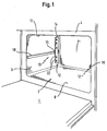
- FIG. 1 shows a furnace muffle 2 of a baking oven in a perspective and schematic representation.
- a lying in the closed position on a front frame 4 and the oven muffle 2 front closing oven door 5 is in an open, horizontally downwardly pivoted position.
- An inventive support member 12 for supporting and guiding a Gargutauflage comprises two holding elements 13, which in the embodiment shown two hook rails 14, which are guided horizontally displaceable on each side walls 6 of the oven muffle on a guide rail 18.
- a respective carriage 16 on each of the two guide rails 18 in slide along the horizontal direction.
- On each carriage 16 a H akenschiene 1 4 is rigidly attached.
- the hook rails 14 which consist of narrow, elongate sheet-metal strips, have a longitudinal extension direction perpendicular to the drawing-out direction and parallel to the side walls 6.
- the hook rails 14 each have a relatively small distance to an upper side 10 and to a bottom surface 8 of the oven muffle 2, so that the cooking product supports can be arranged as needed near or away from the upper or lower heat.
- the guide rails 18 extend expediently over approximately the same length, which corresponds to a depth of the oven muffle 2. In this way, the carriage 16 can be moved with the attached hook rails 14 approximately over the entire depth of the oven muffle 2.
- the guide rails 18 are each arranged in a central region of the side walls 6, so that an impairment of heating elements of a top or bottom heat is given by the guide rail 18 and the carriage 16 and the attached hook rail 14k.
- the support member 12 may be significantly more compact with the same stability.
- each hook rail 14 has in each case five spaced-apart grooves 22, each of which defines an insertion height for a product support.
- they may each have an embossing along their longitudinal direction, which can provide an increase in their flexural rigidity and thus prevent contact with the side walls 6, even if several Gargutauflagen are mounted with correspondingly high loads.
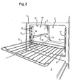
- FIG. 2 shows the hook rails 14 in a front removal position, in which both carriages 16 with the attached hook rails 14 each at a front stop stand near the front frame 4.
- a cooking product support 24 is suspended in a second position from below into the corresponding grooves 22.
- a further development of the mounting part 12 according to the invention may lie in a combination with telescopic extensions.
- a so-called. Full extension can be realized, in which the Gargutauflage 24 can be pulled out into a position in front of the front frame 4.
- the illustrated embodiment with the rail extension only allows a partial extract, in which a rear edge of the Gargutauflage 24 is still in the removal position within the oven muffle 2.
- the guide rails 18 and the carriages sliding thereon are mounted in a corresponding bulged recess of the side wall 6, whereby the space requirement of the holding element 12 is minimized. Possibly. can satisfy a slightly narrower oven muffle for receiving unchanged wide Gargutauflagen.
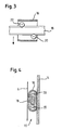
- FIG. 3 shows a first variant of a guide of the carriage 16 on the guide rail 18.
- each two rolling elements 20 are rotatably mounted.
- a rolling element 20 slides on an upper side or on an upper edge of the guide rail 18.
- the other rolling element 20 slides on a lower side or on a lower edge of the guide rail 18.
- the weight exerted by the cooking support supports the weight in FIG FIG. 3 shown arrangement, each with a rolling element 20 above and below the guide rail 18 sufficient.
- the rolling elements 20 are arranged offset from each other in the carriage 16, so that by tilting the carriage 16, this can possibly be unhooked from the guide rail 18 and removed.
- the force exerted by a Gargutauflage weight moment which provides for a stabilization of the carriage 16 is indicated by an arrow.
- at the bottom and / or bottom two rolling elements may be provided, as in FIG. 5 is shown.
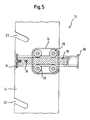
- FIG. 4 shows a sectional view of a holding member 13 of the support member 12 in a viewing direction parallel to the extension direction of the carriage 16.
- the guide rail 18 is firmly anchored in the side wall 6 and has a vertical guide portion with each rounded upper and lower edges, which at the same time the running surfaces for Forming rolling elements 20.
- the rolling elements 20 are each formed in the embodiment shown as einschalige Rotationshyperboloide whose treads grip the running surfaces of the guide rail 18 on both sides.
- the hook rail 14 is rigidly secured.
- FIG. 5 and 6 show in two views or partial sections an alternative embodiment of the support member 12, in which in each carriage 16 each four rolling elements 20 are rotatably mounted.
- Each two spaced rolling elements 20 slide on the upper and on the lower edge of the guide rail 18.
- This has a front stop 34 and a rear stop 36, to which each of the carriage 16 can abut.
- the stops 34, 36 define the maximum travel that the carriage 16 can lay back on the guide rail 18.
- the guide rail 18 is anchored via a plurality of attachment points 38 on the side wall.
- FIG. 5 illustrates an offset mounting of the hook rail 14 on the carriage 16 so that it is moved closer to the front frame of the oven muffle in the removal position. The hanging and removing the Gargutauflage can thereby possibly be facilitated.
- the carriage 16 has a cup-shaped contour with one-sided suspension of the rolling elements 20.
- the hook rail 14 is fixed, while the open side facing the side wall 6 of the oven muffle.
- the carriage 16 largely surrounds the guide rail 18, so that overall a very compact and space-saving unit is formed.
- the rolling elements are formed in the second variant as a symmetrical double cone, each with blunt end faces, the middle edge slides in a corresponding grave-shaped track of the guide rail.
- This alternative embodiment of the carriage and the guide rail is characterized by particular compactness.
- the support member 12 with the two support members 13 may be made particularly narrow and space-saving in this way, so that the width of the oven muffle is hardly increased compared to a furnace muffle provided with conventional inserts.
- the attached to the side walls 6 of the oven muffle 2 guide rail is recessed in a corresponding recess, so that substantially only the hook rail protrudes at a small distance from the side wall 6 of the oven muffle from the side outline. In this way, a further reduction in the width of the furnace muffle can be achieved.
- Gargutauflage 24 illustrates that is located approximately in the middle of the guide rail 18 in a middle insertion position.
- FIG. 7 shows a perspective view of a preferred embodiment of the support member 12, in which the two hook rails 14 are connected by a connecting strut 26 with each other. In this way it can be avoided that one of the hook rails 14 is accidentally pushed back when hanging the Gargutierlage.
- FIG. 8 shows a possible embodiment of a locking device 27, which consists of a spring-loaded ball 30 which can engage in a recess 32 of the guide rail 18.
- the ball 30 is preferably held in the carriage and can engage in a depression 32 located in the front area of the guide rail 18 and thus defining a detent in the removal position. Possibly.
- a further depression may be provided in a rear region of the guide rail 18, which defines a further latching position in the cooking position of the cooking product support.
- the latching positions preferably correspond with the corresponding stops of the carriage (see. FIG. 6 ), so that in practice the maximum displacement of the retaining element is utilized.
- the illustrated rolling bearing of the carriage can not have conventional grease lubrication.
- rolling pairings made of ceramic or with a ceramic coating are particularly suitable.
- Such Wälzproung also offers the further advantage that the support member 12 can be electrically isolated from the oven muffle. This allows a microwave fitness of the oven, thereby the insulation of the holding element no spark and high voltage flashovers are to be feared.
- the carriage and the hook rails comes, for example, aluminum, stainless steel or brass in question, which may optionally have a ceramic coating on the guide rail.
Landscapes
- Engineering & Computer Science (AREA)
- Chemical & Material Sciences (AREA)
- Combustion & Propulsion (AREA)
- Mechanical Engineering (AREA)
- General Engineering & Computer Science (AREA)
- Baking, Grill, Roasting (AREA)
- Electric Ovens (AREA)
- Tunnel Furnaces (AREA)
- Ceramic Capacitors (AREA)
- Fixed Capacitors And Capacitor Manufacturing Machines (AREA)
Claims (4)
- Four comprenant une pièce de support (12) guidée horizontalement dans un moufle de four (2), destinée à loger et maintenir un support pour denrées à cuire (24), laquelle pièce de support est déplaçable entre une position de cuisson dans le moufle de four (2) et une position de retrait située au moins en partie devant celle-là, la pièce de support (12) présentant deux éléments de maintien (13) guidés par un chariot (16), lesquels sont disposés sur des parois latérales opposées (6) et à écart d'un côté supérieur (10) resp. d'un côté inférieur (8) du moufle de four (2), l'élément de maintien (13) comprenant un rail à crochets (14) qui s'étend verticalement de sorte que sa direction d'étendue longitudinale est disposée perpendiculairement à une direction d'extraction, et qui, sur la paroi latérale (6) du moufle de four (2), est guidé de manière déplaçable horizontalement sur un rail de guidage (18), le rail à crochets (14) étant fixé sur le chariot (16) du fait qu'il est fixé de manière rigide sur le chariot (16), et présentant respectivement un écart relativement moindre par rapport à un côté supérieur (10) ainsi qu'à une surface de fond (8) du moufle de four (2), caractérisé en ce que le chariot est disposé sur la paroi latérale (6) du moufle de four (2) respectivement dans une partie médiane en hauteur, les rails de guidage (18) ainsi que les chariots (16) coulissant dessus étant respectivement montés dans un approfondissement des parois latérales (6), bombé de manière correspondante.
- Four selon la revendication 1, caractérisé en ce que les rails à crochets (14) sont couplés entre eux au moins d'un entretoisement transversal (26).
- Four selon l'une quelconque des revendications précédentes, caractérisé par une position d'enclenchement des chariots (16) au moins dans la position de retrait.
- Four selon l'une quelconque des revendications précédentes, caractérisé par un chariot (16) logé dans des paliers à roulement.
Applications Claiming Priority (3)
| Application Number | Priority Date | Filing Date | Title |
|---|---|---|---|
| DE10240146A DE10240146A1 (de) | 2002-08-30 | 2002-08-30 | Backofen mit Linearauszug |
| DE10240146 | 2002-08-30 | ||
| PCT/EP2003/009188 WO2004025187A1 (fr) | 2002-08-30 | 2003-08-19 | Four a systeme sortant lineaire |
Publications (3)
| Publication Number | Publication Date |
|---|---|
| EP1537365A1 EP1537365A1 (fr) | 2005-06-08 |
| EP1537365B1 EP1537365B1 (fr) | 2012-03-07 |
| EP1537365B2 true EP1537365B2 (fr) | 2016-02-24 |
Family
ID=31502182
Family Applications (1)
| Application Number | Title | Priority Date | Filing Date |
|---|---|---|---|
| EP03747912.8A Expired - Lifetime EP1537365B2 (fr) | 2002-08-30 | 2003-08-19 | Four a systeme sortant lineaire |
Country Status (8)
| Country | Link |
|---|---|
| US (1) | US20050241495A1 (fr) |
| EP (1) | EP1537365B2 (fr) |
| AT (1) | ATE548610T1 (fr) |
| AU (1) | AU2003266997A1 (fr) |
| BR (1) | BR0313948A (fr) |
| DE (1) | DE10240146A1 (fr) |
| ES (1) | ES2381035T5 (fr) |
| WO (1) | WO2004025187A1 (fr) |
Cited By (1)
| Publication number | Priority date | Publication date | Assignee | Title |
|---|---|---|---|---|
| CN106235901A (zh) * | 2016-10-19 | 2016-12-21 | 范希波 | 酒类燃料烧烤炉及其烧烤方法 |
Families Citing this family (27)
| Publication number | Priority date | Publication date | Assignee | Title |
|---|---|---|---|---|
| DE102004031723A1 (de) * | 2004-06-30 | 2006-01-26 | BSH Bosch und Siemens Hausgeräte GmbH | Auszugsystem |
| DE102005036990A1 (de) | 2005-08-05 | 2007-02-08 | BSH Bosch und Siemens Hausgeräte GmbH | Hausgeräteauszugsvorrichtung |
| DE102005036987A1 (de) * | 2005-08-05 | 2007-02-08 | BSH Bosch und Siemens Hausgeräte GmbH | Hausgeräteauszugsvorrichtung |
| DE102005036986A1 (de) * | 2005-08-05 | 2007-02-15 | BSH Bosch und Siemens Hausgeräte GmbH | Hausgeräteauszugsvorrichtung |
| DE102005036989A1 (de) | 2005-08-05 | 2007-02-08 | BSH Bosch und Siemens Hausgeräte GmbH | Hausgeräteauszugsvorrichtung |
| DE102005044627A1 (de) * | 2005-09-19 | 2007-03-22 | BSH Bosch und Siemens Hausgeräte GmbH | Gargerät |
| DE102005044643A1 (de) * | 2005-09-19 | 2007-03-29 | BSH Bosch und Siemens Hausgeräte GmbH | Gargerät |
| DE102008010501A1 (de) | 2008-02-22 | 2009-08-27 | BSH Bosch und Siemens Hausgeräte GmbH | Auszugssystem für ein Gargerät und Gargerät |
| DE202008004658U1 (de) | 2008-04-04 | 2009-08-13 | Paul Hettich Gmbh & Co. Kg | Ausziehführung und Backofen |
| DE202008006302U1 (de) | 2008-05-07 | 2009-09-10 | Paul Hettich & Co Kg | Ausziehführung |
| EP2187134B1 (fr) * | 2008-11-18 | 2013-06-05 | Electrolux Home Products Corporation N.V. | Four, plus particulièrement un four ménager |
| DE102009000305B4 (de) * | 2009-01-19 | 2021-05-12 | BSH Hausgeräte GmbH | Pyrolysefeste Gargerätevorrichtung |
| EP2236941A1 (fr) * | 2009-03-28 | 2010-10-06 | Electrolux Home Products Corporation N.V. | Support pour plaques de cuisson extractibles et/ou grilles de cuisson |
| ES2394703B1 (es) * | 2010-12-22 | 2014-02-28 | BSH Electrodomésticos España S.A. | Dispositivo de sujeción de soporte de producto de cocción |
| DE102012217998A1 (de) * | 2012-10-02 | 2014-04-03 | BSH Bosch und Siemens Hausgeräte GmbH | Vorrichtung für einen Gargutträger und Gargerät mit einer derartigen Vorrichtung |
| DE102012222028A1 (de) | 2012-12-03 | 2014-06-05 | BSH Bosch und Siemens Hausgeräte GmbH | Haltevorrichtung für einen Gargutträger sowie Gargerät mit einer derartigen Haltevorrichtung |
| EP2757322B1 (fr) * | 2013-01-18 | 2017-12-13 | Electrolux Home Products Corporation N.V. | Système de grille latérale pour cavité de four |
| DE102013214853A1 (de) * | 2013-07-30 | 2015-02-05 | BSH Bosch und Siemens Hausgeräte GmbH | Auszugsvorrichtung für einen Gargutträger eines Mikrowellengargeräts und Mikrowellengargerät |
| DE102013214852A1 (de) * | 2013-07-30 | 2015-02-05 | BSH Bosch und Siemens Hausgeräte GmbH | Auszugsvorrichtung für einen Gargutträger eines Mikrowellengargeräts und Mikrowellengargerät |
| DE102013225405A1 (de) * | 2013-12-10 | 2015-06-11 | BSH Hausgeräte GmbH | Schienenauszugsvorrichtung für ein Mikrowellengargerät mit spezifisch positionierten Rastelementen zur Verrastung der Schienen |
| DE102014201429A1 (de) | 2014-01-27 | 2015-07-30 | BSH Hausgeräte GmbH | Halte- und Führungsvorrichtung mit einer Schienenauszugseinrichtung mit einem mehrebigen Traggitter und Gargerät mit einer derartigen Vorrichtung |
| DE102014214170A1 (de) * | 2014-07-21 | 2016-02-11 | BSH Hausgeräte GmbH | Laufrolle, Auszugssystem und Haushaltsgargerät |
| DE102014217633A1 (de) * | 2014-09-03 | 2016-03-03 | BSH Hausgeräte GmbH | Auszugssystem und Haushaltsgargerät |
| DE102016218757A1 (de) * | 2016-09-28 | 2018-03-29 | BSH Hausgeräte GmbH | Wälzkörpervorrichtung für eine Schienenauszugsvorrichtung, Schienenauszugsvorrichtung und Haushaltsgerät |
| DE202017006448U1 (de) * | 2017-12-14 | 2019-03-15 | Grass Gmbh | Erhitzungsvorrichtung, insbesondere Ofen |
| DE102018109429A1 (de) * | 2018-04-19 | 2019-10-24 | Paul Hettich Gmbh & Co. Kg | Backofen |
| DE102020215682A1 (de) | 2020-12-10 | 2022-06-15 | BSH Hausgeräte GmbH | Backblech und Gargutträger mit spezifischen Führungssystemen, sowie Gargerät |
Citations (5)
| Publication number | Priority date | Publication date | Assignee | Title |
|---|---|---|---|---|
| US2987363A (en) † | 1957-12-13 | 1961-06-06 | Charles L Morse | Cooking oven |
| EP0443329A2 (fr) † | 1990-02-21 | 1991-08-28 | BOSCH-SIEMENS HAUSGERÄTE GmbH | Four de cuisson |
| DE19824167A1 (de) † | 1998-05-29 | 1999-12-02 | Bsh Bosch Siemens Hausgeraete | Teleskop-Auszugsvorrichtung für Möbel und Hausgeräte |
| DE19825323A1 (de) † | 1998-06-05 | 1999-12-09 | Bsh Bosch Siemens Hausgeraete | Backofen mit einem Laufwagen für ein Halterungsteil für Gargutträger |
| DE19817499C1 (de) † | 1998-04-20 | 1999-12-09 | Bsh Bosch Siemens Hausgeraete | Backofen mit Teleskopauszug |
Family Cites Families (22)
| Publication number | Priority date | Publication date | Assignee | Title |
|---|---|---|---|---|
| US2899255A (en) * | 1959-08-11 | Range with pull-out shelf | ||
| US1063183A (en) * | 1912-01-29 | 1913-06-03 | Stamford R Christian | Withdrawing skeleton oven. |
| US1614167A (en) * | 1926-11-01 | 1927-01-11 | Cribben & Sexton Company | Broiler oven |
| US1998343A (en) * | 1931-12-17 | 1935-04-16 | Teller Stove Designing Corp | Cooking range and stove |
| US2130167A (en) * | 1936-06-05 | 1938-09-13 | Harry C Weiskittel Co Inc | Stove construction |
| US2132737A (en) * | 1937-04-07 | 1938-10-11 | Estate Stove Co | Stove |
| US3106202A (en) * | 1959-01-16 | 1963-10-08 | Arthur A Arduna | Oven with rack operating mechanism |
| US3575484A (en) * | 1969-05-12 | 1971-04-20 | Gen Motors Corp | Convertibel cantilevered shelf |
| US4548193A (en) * | 1984-09-10 | 1985-10-22 | Emmanuel Marogil | Multi-purpose portable outdoor cooking stand |
| CH669509A5 (fr) * | 1986-02-27 | 1989-03-31 | Uniboard Ag | |
| ES1011203Y (es) * | 1989-07-28 | 1990-09-01 | Ulgor, S. Coop. Ltda. | Horno de cocina perfeccionado |
| DE8915017U1 (fr) * | 1989-12-21 | 1990-03-01 | Bosch-Siemens Hausgeraete Gmbh, 8000 Muenchen, De | |
| US5474378A (en) * | 1993-12-03 | 1995-12-12 | Whirlpool Corporation | Adjustable support apparatus for a dishrack |
| US5657878A (en) * | 1995-07-12 | 1997-08-19 | Illinois Tool Works Inc. | Adjustable height mechanism for a dishwasher rack |
| US5860716A (en) * | 1997-03-28 | 1999-01-19 | White Consolidated Industries, Inc. | Dishwasher rack adjustment mechanism |
| DE19737494A1 (de) * | 1997-08-28 | 1999-03-04 | Kueppersbusch | Gargutträger für einen Backofen |
| US6148813A (en) * | 1999-08-17 | 2000-11-21 | Maytag Corporation | Telescoping oven rack assembly |
| DE19949239A1 (de) * | 1999-10-13 | 2001-04-26 | Aeg Hausgeraete Gmbh | Auszugsvorrichtung für Gargutträger im Garraum von Garöfen |
| DE19951267B4 (de) * | 1999-10-25 | 2005-05-12 | Accuride International Gmbh | Gargutträgersystem für einen Backofen |
| PT1158185E (pt) * | 2000-05-26 | 2005-11-30 | Hettich Paul Gmbh & Co | Elemento de fixacao rapida |
| DE10054954B4 (de) | 2000-11-06 | 2004-10-21 | AEG Hausgeräte GmbH | Garofen mit Auszugsvorrichtung für Gargutträger |
| US6938617B2 (en) * | 2002-07-10 | 2005-09-06 | Accuride International Inc. | Oven assembly with slides |
-
2002
- 2002-08-30 DE DE10240146A patent/DE10240146A1/de not_active Withdrawn
-
2003
- 2003-08-19 ES ES03747912.8T patent/ES2381035T5/es not_active Expired - Lifetime
- 2003-08-19 AU AU2003266997A patent/AU2003266997A1/en not_active Abandoned
- 2003-08-19 EP EP03747912.8A patent/EP1537365B2/fr not_active Expired - Lifetime
- 2003-08-19 US US10/525,997 patent/US20050241495A1/en not_active Abandoned
- 2003-08-19 WO PCT/EP2003/009188 patent/WO2004025187A1/fr not_active Application Discontinuation
- 2003-08-19 BR BR0313948-4A patent/BR0313948A/pt not_active Application Discontinuation
- 2003-08-19 AT AT03747912T patent/ATE548610T1/de active
Patent Citations (5)
| Publication number | Priority date | Publication date | Assignee | Title |
|---|---|---|---|---|
| US2987363A (en) † | 1957-12-13 | 1961-06-06 | Charles L Morse | Cooking oven |
| EP0443329A2 (fr) † | 1990-02-21 | 1991-08-28 | BOSCH-SIEMENS HAUSGERÄTE GmbH | Four de cuisson |
| DE19817499C1 (de) † | 1998-04-20 | 1999-12-09 | Bsh Bosch Siemens Hausgeraete | Backofen mit Teleskopauszug |
| DE19824167A1 (de) † | 1998-05-29 | 1999-12-02 | Bsh Bosch Siemens Hausgeraete | Teleskop-Auszugsvorrichtung für Möbel und Hausgeräte |
| DE19825323A1 (de) † | 1998-06-05 | 1999-12-09 | Bsh Bosch Siemens Hausgeraete | Backofen mit einem Laufwagen für ein Halterungsteil für Gargutträger |
Cited By (2)
| Publication number | Priority date | Publication date | Assignee | Title |
|---|---|---|---|---|
| CN106235901A (zh) * | 2016-10-19 | 2016-12-21 | 范希波 | 酒类燃料烧烤炉及其烧烤方法 |
| CN106235901B (zh) * | 2016-10-19 | 2019-01-18 | 范希波 | 酒类燃料烧烤炉及其烧烤方法 |
Also Published As
| Publication number | Publication date |
|---|---|
| EP1537365A1 (fr) | 2005-06-08 |
| BR0313948A (pt) | 2005-07-12 |
| ES2381035T5 (es) | 2016-05-06 |
| ES2381035T3 (es) | 2012-05-22 |
| EP1537365B1 (fr) | 2012-03-07 |
| DE10240146A1 (de) | 2004-03-11 |
| AU2003266997A1 (en) | 2004-04-30 |
| US20050241495A1 (en) | 2005-11-03 |
| ATE548610T1 (de) | 2012-03-15 |
| WO2004025187A1 (fr) | 2004-03-25 |
Similar Documents
| Publication | Publication Date | Title |
|---|---|---|
| EP1537365B2 (fr) | Four a systeme sortant lineaire | |
| EP1540253B1 (fr) | Extension a rails et extension telescopique a rails | |
| EP1761731B1 (fr) | Systeme de guidage lineaire destine a un tiroir | |
| EP3205960B1 (fr) | Appareil frigorifique ménager et procédé pour le montage de l'appareil frigorifique ménager | |
| DE202010008825U1 (de) | Auszugvorrichtung für eine schubladenartige Einrichtung in einem Geräte- oder Möbelkorpus | |
| DE3815440A1 (de) | Teleskopeinschubvorrichtung zur auflage von garguttraegern, insbesondere fuer backoefen | |
| EP3750447A1 (fr) | Agencement des tiroirs | |
| EP3022506A1 (fr) | Appareil électroménager frigorifique pourvu d'une clayette et partie de préhension agencée coulissante sur la clayette | |
| EP1344985B1 (fr) | Four de cuisson et chariot de four | |
| DE10330348A1 (de) | Gargutträgerauszugsystem | |
| EP2994012B1 (fr) | Ensemble support de raccord emboîtable et raccord emboîtable | |
| DE102008018235A1 (de) | Kältegerät | |
| EP2908056A2 (fr) | Dispositif de guidage et de retenue doté d'un dispositif à glissière avec une grille de support à plusieurs niveaux et appareil de cuisson doté d'un tel dispositif | |
| AT520691B1 (de) | Führungssystem | |
| DE102005002156A1 (de) | Küchendunstabzugsvorrichtung | |
| DE102010016594A1 (de) | Auszugsführung für Möbel oder Haushaltsgeräte | |
| DE19706246B4 (de) | Teleskop-Schrankauszug | |
| EP3850986B1 (fr) | Tiroir d'armoire pour un élément d'armoire | |
| EP2719955A2 (fr) | Dispositif à glissière pour un support pour produits de cuisson | |
| DE202018101195U1 (de) | Fachboden und Fachbodenanordnung | |
| DE102012222210A1 (de) | Zur verdeckten Anordnung vorgesehenes Ecklager | |
| DE102016218757A1 (de) | Wälzkörpervorrichtung für eine Schienenauszugsvorrichtung, Schienenauszugsvorrichtung und Haushaltsgerät | |
| EP1750061A2 (fr) | Dispositif d'extraction de plaques pour un appareil ménager | |
| EP1750065A2 (fr) | Système d'extraction pour appareil ménager | |
| DE102005036989A1 (de) | Hausgeräteauszugsvorrichtung |
Legal Events
| Date | Code | Title | Description |
|---|---|---|---|
| PUAI | Public reference made under article 153(3) epc to a published international application that has entered the european phase |
Free format text: ORIGINAL CODE: 0009012 |
|
| 17P | Request for examination filed |
Effective date: 20050330 |
|
| AK | Designated contracting states |
Kind code of ref document: A1 Designated state(s): AT BE BG CH CY CZ DE DK EE ES FI FR GB GR HU IE IT LI LU MC NL PT RO SE SI SK TR |
|
| AX | Request for extension of the european patent |
Extension state: AL LT LV MK |
|
| DAX | Request for extension of the european patent (deleted) | ||
| RIN1 | Information on inventor provided before grant (corrected) |
Inventor name: MALLINGER, PETER Inventor name: SCHILCHER, MICHAEL Inventor name: FELDMANN, KERSTIN Inventor name: GOETZENDORFER, FRANZ Inventor name: ROGENHOFER, HANS Inventor name: MAIER, THOMAS Inventor name: FERNSEBNER, HORST Inventor name: MLOTEK, DIETER |
|
| 17Q | First examination report despatched |
Effective date: 20071010 |
|
| RAP1 | Party data changed (applicant data changed or rights of an application transferred) |
Owner name: BSH BOSCH UND SIEMENS HAUSGERAETE GMBH |
|
| GRAP | Despatch of communication of intention to grant a patent |
Free format text: ORIGINAL CODE: EPIDOSNIGR1 |
|
| GRAS | Grant fee paid |
Free format text: ORIGINAL CODE: EPIDOSNIGR3 |
|
| GRAA | (expected) grant |
Free format text: ORIGINAL CODE: 0009210 |
|
| AK | Designated contracting states |
Kind code of ref document: B1 Designated state(s): AT BE BG CH CY CZ DE DK EE ES FI FR GB GR HU IE IT LI LU MC NL PT RO SE SI SK TR |
|
| REG | Reference to a national code |
Ref country code: GB Ref legal event code: FG4D Free format text: NOT ENGLISH |
|
| REG | Reference to a national code |
Ref country code: AT Ref legal event code: REF Ref document number: 548610 Country of ref document: AT Kind code of ref document: T Effective date: 20120315 Ref country code: CH Ref legal event code: EP |
|
| REG | Reference to a national code |
Ref country code: IE Ref legal event code: FG4D Free format text: LANGUAGE OF EP DOCUMENT: GERMAN |
|
| REG | Reference to a national code |
Ref country code: DE Ref legal event code: R096 Ref document number: 50314252 Country of ref document: DE Effective date: 20120503 |
|
| REG | Reference to a national code |
Ref country code: ES Ref legal event code: FG2A Ref document number: 2381035 Country of ref document: ES Kind code of ref document: T3 Effective date: 20120522 |
|
| REG | Reference to a national code |
Ref country code: NL Ref legal event code: VDEP Effective date: 20120307 |
|
| PG25 | Lapsed in a contracting state [announced via postgrant information from national office to epo] |
Ref country code: NL Free format text: LAPSE BECAUSE OF FAILURE TO SUBMIT A TRANSLATION OF THE DESCRIPTION OR TO PAY THE FEE WITHIN THE PRESCRIBED TIME-LIMIT Effective date: 20120307 |
|
| PG25 | Lapsed in a contracting state [announced via postgrant information from national office to epo] |
Ref country code: GR Free format text: LAPSE BECAUSE OF FAILURE TO SUBMIT A TRANSLATION OF THE DESCRIPTION OR TO PAY THE FEE WITHIN THE PRESCRIBED TIME-LIMIT Effective date: 20120608 Ref country code: FI Free format text: LAPSE BECAUSE OF FAILURE TO SUBMIT A TRANSLATION OF THE DESCRIPTION OR TO PAY THE FEE WITHIN THE PRESCRIBED TIME-LIMIT Effective date: 20120307 |
|
| PG25 | Lapsed in a contracting state [announced via postgrant information from national office to epo] |
Ref country code: CY Free format text: LAPSE BECAUSE OF FAILURE TO SUBMIT A TRANSLATION OF THE DESCRIPTION OR TO PAY THE FEE WITHIN THE PRESCRIBED TIME-LIMIT Effective date: 20120307 |
|
| PG25 | Lapsed in a contracting state [announced via postgrant information from national office to epo] |
Ref country code: SI Free format text: LAPSE BECAUSE OF FAILURE TO SUBMIT A TRANSLATION OF THE DESCRIPTION OR TO PAY THE FEE WITHIN THE PRESCRIBED TIME-LIMIT Effective date: 20120307 Ref country code: RO Free format text: LAPSE BECAUSE OF FAILURE TO SUBMIT A TRANSLATION OF THE DESCRIPTION OR TO PAY THE FEE WITHIN THE PRESCRIBED TIME-LIMIT Effective date: 20120307 Ref country code: CZ Free format text: LAPSE BECAUSE OF FAILURE TO SUBMIT A TRANSLATION OF THE DESCRIPTION OR TO PAY THE FEE WITHIN THE PRESCRIBED TIME-LIMIT Effective date: 20120307 Ref country code: SE Free format text: LAPSE BECAUSE OF FAILURE TO SUBMIT A TRANSLATION OF THE DESCRIPTION OR TO PAY THE FEE WITHIN THE PRESCRIBED TIME-LIMIT Effective date: 20120307 Ref country code: EE Free format text: LAPSE BECAUSE OF FAILURE TO SUBMIT A TRANSLATION OF THE DESCRIPTION OR TO PAY THE FEE WITHIN THE PRESCRIBED TIME-LIMIT Effective date: 20120307 |
|
| PG25 | Lapsed in a contracting state [announced via postgrant information from national office to epo] |
Ref country code: SK Free format text: LAPSE BECAUSE OF FAILURE TO SUBMIT A TRANSLATION OF THE DESCRIPTION OR TO PAY THE FEE WITHIN THE PRESCRIBED TIME-LIMIT Effective date: 20120307 Ref country code: PT Free format text: LAPSE BECAUSE OF FAILURE TO SUBMIT A TRANSLATION OF THE DESCRIPTION OR TO PAY THE FEE WITHIN THE PRESCRIBED TIME-LIMIT Effective date: 20120709 |
|
| PLBI | Opposition filed |
Free format text: ORIGINAL CODE: 0009260 |
|
| PLAX | Notice of opposition and request to file observation + time limit sent |
Free format text: ORIGINAL CODE: EPIDOSNOBS2 |
|
| 26 | Opposition filed |
Opponent name: ELECTROLUX ROTHENBURG GMBH FACTORY AND DEVELOPMENT Effective date: 20121207 |
|
| PG25 | Lapsed in a contracting state [announced via postgrant information from national office to epo] |
Ref country code: DK Free format text: LAPSE BECAUSE OF FAILURE TO SUBMIT A TRANSLATION OF THE DESCRIPTION OR TO PAY THE FEE WITHIN THE PRESCRIBED TIME-LIMIT Effective date: 20120307 |
|
| PLBB | Reply of patent proprietor to notice(s) of opposition received |
Free format text: ORIGINAL CODE: EPIDOSNOBS3 |
|
| BERE | Be: lapsed |
Owner name: BSH BOSCH UND SIEMENS HAUSGERATE G.M.B.H. Effective date: 20120831 |
|
| REG | Reference to a national code |
Ref country code: DE Ref legal event code: R026 Ref document number: 50314252 Country of ref document: DE Effective date: 20121207 |
|
| REG | Reference to a national code |
Ref country code: CH Ref legal event code: PL |
|
| PG25 | Lapsed in a contracting state [announced via postgrant information from national office to epo] |
Ref country code: MC Free format text: LAPSE BECAUSE OF NON-PAYMENT OF DUE FEES Effective date: 20120831 |
|
| GBPC | Gb: european patent ceased through non-payment of renewal fee |
Effective date: 20120819 |
|
| PG25 | Lapsed in a contracting state [announced via postgrant information from national office to epo] |
Ref country code: CH Free format text: LAPSE BECAUSE OF NON-PAYMENT OF DUE FEES Effective date: 20120831 Ref country code: LI Free format text: LAPSE BECAUSE OF NON-PAYMENT OF DUE FEES Effective date: 20120831 |
|
| REG | Reference to a national code |
Ref country code: FR Ref legal event code: ST Effective date: 20130430 |
|
| REG | Reference to a national code |
Ref country code: IE Ref legal event code: MM4A |
|
| PG25 | Lapsed in a contracting state [announced via postgrant information from national office to epo] |
Ref country code: BE Free format text: LAPSE BECAUSE OF NON-PAYMENT OF DUE FEES Effective date: 20120831 |
|
| PG25 | Lapsed in a contracting state [announced via postgrant information from national office to epo] |
Ref country code: IE Free format text: LAPSE BECAUSE OF NON-PAYMENT OF DUE FEES Effective date: 20120819 Ref country code: GB Free format text: LAPSE BECAUSE OF NON-PAYMENT OF DUE FEES Effective date: 20120819 Ref country code: BG Free format text: LAPSE BECAUSE OF FAILURE TO SUBMIT A TRANSLATION OF THE DESCRIPTION OR TO PAY THE FEE WITHIN THE PRESCRIBED TIME-LIMIT Effective date: 20120607 |
|
| PG25 | Lapsed in a contracting state [announced via postgrant information from national office to epo] |
Ref country code: FR Free format text: LAPSE BECAUSE OF NON-PAYMENT OF DUE FEES Effective date: 20120831 |
|
| REG | Reference to a national code |
Ref country code: AT Ref legal event code: MM01 Ref document number: 548610 Country of ref document: AT Kind code of ref document: T Effective date: 20120831 |
|
| PG25 | Lapsed in a contracting state [announced via postgrant information from national office to epo] |
Ref country code: AT Free format text: LAPSE BECAUSE OF NON-PAYMENT OF DUE FEES Effective date: 20120831 |
|
| PG25 | Lapsed in a contracting state [announced via postgrant information from national office to epo] |
Ref country code: LU Free format text: LAPSE BECAUSE OF NON-PAYMENT OF DUE FEES Effective date: 20120819 |
|
| PG25 | Lapsed in a contracting state [announced via postgrant information from national office to epo] |
Ref country code: HU Free format text: LAPSE BECAUSE OF FAILURE TO SUBMIT A TRANSLATION OF THE DESCRIPTION OR TO PAY THE FEE WITHIN THE PRESCRIBED TIME-LIMIT Effective date: 20030819 |
|
| RAP2 | Party data changed (patent owner data changed or rights of a patent transferred) |
Owner name: BSH HAUSGERAETE GMBH |
|
| REG | Reference to a national code |
Ref country code: DE Ref legal event code: R081 Ref document number: 50314252 Country of ref document: DE Owner name: BSH HAUSGERAETE GMBH, DE Free format text: FORMER OWNER: BSH BOSCH UND SIEMENS HAUSGERAETE GMBH, 81739 MUENCHEN, DE Effective date: 20120314 Ref country code: DE Ref legal event code: R081 Ref document number: 50314252 Country of ref document: DE Owner name: BSH HAUSGERAETE GMBH, DE Free format text: FORMER OWNER: BSH BOSCH UND SIEMENS HAUSGERAETE GMBH, 81739 MUENCHEN, DE Effective date: 20150407 |
|
| REG | Reference to a national code |
Ref country code: ES Ref legal event code: PC2A Owner name: BSH HAUSGERATE GMBH Effective date: 20150527 |
|
| PUAH | Patent maintained in amended form |
Free format text: ORIGINAL CODE: 0009272 |
|
| STAA | Information on the status of an ep patent application or granted ep patent |
Free format text: STATUS: PATENT MAINTAINED AS AMENDED |
|
| 27A | Patent maintained in amended form |
Effective date: 20160224 |
|
| AK | Designated contracting states |
Kind code of ref document: B2 Designated state(s): AT BE BG CH CY CZ DE DK EE ES FI FR GB GR HU IE IT LI LU MC NL PT RO SE SI SK TR |
|
| REG | Reference to a national code |
Ref country code: DE Ref legal event code: R102 Ref document number: 50314252 Country of ref document: DE |
|
| REG | Reference to a national code |
Ref country code: ES Ref legal event code: DC2A Ref document number: 2381035 Country of ref document: ES Kind code of ref document: T5 Effective date: 20160506 |
|
| PGFP | Annual fee paid to national office [announced via postgrant information from national office to epo] |
Ref country code: DE Payment date: 20160831 Year of fee payment: 14 Ref country code: IT Payment date: 20160823 Year of fee payment: 14 |
|
| PGFP | Annual fee paid to national office [announced via postgrant information from national office to epo] |
Ref country code: ES Payment date: 20160829 Year of fee payment: 14 Ref country code: TR Payment date: 20160809 Year of fee payment: 14 |
|
| REG | Reference to a national code |
Ref country code: DE Ref legal event code: R119 Ref document number: 50314252 Country of ref document: DE |
|
| PG25 | Lapsed in a contracting state [announced via postgrant information from national office to epo] |
Ref country code: DE Free format text: LAPSE BECAUSE OF NON-PAYMENT OF DUE FEES Effective date: 20180301 |
|
| PG25 | Lapsed in a contracting state [announced via postgrant information from national office to epo] |
Ref country code: IT Free format text: LAPSE BECAUSE OF NON-PAYMENT OF DUE FEES Effective date: 20170819 |
|
| REG | Reference to a national code |
Ref country code: ES Ref legal event code: FD2A Effective date: 20181025 |
|
| PG25 | Lapsed in a contracting state [announced via postgrant information from national office to epo] |
Ref country code: ES Free format text: LAPSE BECAUSE OF NON-PAYMENT OF DUE FEES Effective date: 20170820 |
|
| PG25 | Lapsed in a contracting state [announced via postgrant information from national office to epo] |
Ref country code: TR Free format text: LAPSE BECAUSE OF NON-PAYMENT OF DUE FEES Effective date: 20170819 |