EP0431160B1 - VERFAHREN ZUR HERSTELLUNG EINES DüNNSCHICHTOXYDSUPRALEITERS - Google Patents
VERFAHREN ZUR HERSTELLUNG EINES DüNNSCHICHTOXYDSUPRALEITERS Download PDFInfo
- Publication number
- EP0431160B1 EP0431160B1 EP89903216A EP89903216A EP0431160B1 EP 0431160 B1 EP0431160 B1 EP 0431160B1 EP 89903216 A EP89903216 A EP 89903216A EP 89903216 A EP89903216 A EP 89903216A EP 0431160 B1 EP0431160 B1 EP 0431160B1
- Authority
- EP
- European Patent Office
- Prior art keywords
- discharge
- substrate
- oxygen
- thin film
- ozone
- Prior art date
- Legal status (The legal status is an assumption and is not a legal conclusion. Google has not performed a legal analysis and makes no representation as to the accuracy of the status listed.)
- Revoked
Links
- 239000010409 thin film Substances 0.000 title claims abstract description 67
- 239000002887 superconductor Substances 0.000 title claims abstract description 65
- 238000000034 method Methods 0.000 title claims description 46
- QVGXLLKOCUKJST-UHFFFAOYSA-N atomic oxygen Chemical compound [O] QVGXLLKOCUKJST-UHFFFAOYSA-N 0.000 claims abstract description 105
- 239000001301 oxygen Substances 0.000 claims abstract description 68
- 229910052760 oxygen Inorganic materials 0.000 claims abstract description 68
- 238000000151 deposition Methods 0.000 claims abstract description 41
- 239000000758 substrate Substances 0.000 claims description 104
- 239000007789 gas Substances 0.000 claims description 40
- CBENFWSGALASAD-UHFFFAOYSA-N Ozone Chemical compound [O-][O+]=O CBENFWSGALASAD-UHFFFAOYSA-N 0.000 claims description 37
- 230000008021 deposition Effects 0.000 claims description 26
- MYMOFIZGZYHOMD-UHFFFAOYSA-N Dioxygen Chemical compound O=O MYMOFIZGZYHOMD-UHFFFAOYSA-N 0.000 claims description 23
- 229910001882 dioxygen Inorganic materials 0.000 claims description 23
- 238000000427 thin-film deposition Methods 0.000 claims description 19
- 238000004519 manufacturing process Methods 0.000 claims description 9
- 239000000470 constituent Substances 0.000 claims description 6
- 238000010884 ion-beam technique Methods 0.000 claims description 6
- 239000002245 particle Substances 0.000 claims description 6
- 239000002994 raw material Substances 0.000 claims description 6
- 238000005229 chemical vapour deposition Methods 0.000 claims description 5
- 230000007935 neutral effect Effects 0.000 claims description 4
- 238000005268 plasma chemical vapour deposition Methods 0.000 claims description 3
- 238000002230 thermal chemical vapour deposition Methods 0.000 claims description 3
- 238000010894 electron beam technology Methods 0.000 claims description 2
- 239000013078 crystal Substances 0.000 abstract description 8
- 125000004430 oxygen atom Chemical group O* 0.000 abstract description 6
- 230000001678 irradiating effect Effects 0.000 abstract description 2
- 239000000126 substance Substances 0.000 abstract 1
- 239000000203 mixture Substances 0.000 description 10
- 238000004544 sputter deposition Methods 0.000 description 9
- 230000008020 evaporation Effects 0.000 description 8
- 238000001704 evaporation Methods 0.000 description 8
- 230000015572 biosynthetic process Effects 0.000 description 7
- 239000000463 material Substances 0.000 description 4
- XUIMIQQOPSSXEZ-UHFFFAOYSA-N Silicon Chemical compound [Si] XUIMIQQOPSSXEZ-UHFFFAOYSA-N 0.000 description 3
- 238000010438 heat treatment Methods 0.000 description 3
- 239000004065 semiconductor Substances 0.000 description 3
- 229910052710 silicon Inorganic materials 0.000 description 3
- 239000010703 silicon Substances 0.000 description 3
- 238000005245 sintering Methods 0.000 description 3
- XKRFYHLGVUSROY-UHFFFAOYSA-N Argon Chemical compound [Ar] XKRFYHLGVUSROY-UHFFFAOYSA-N 0.000 description 2
- 229910002480 Cu-O Inorganic materials 0.000 description 2
- 239000004593 Epoxy Substances 0.000 description 2
- XAGFODPZIPBFFR-UHFFFAOYSA-N aluminium Chemical compound [Al] XAGFODPZIPBFFR-UHFFFAOYSA-N 0.000 description 2
- 229910052782 aluminium Inorganic materials 0.000 description 2
- 239000010949 copper Substances 0.000 description 2
- 238000007599 discharging Methods 0.000 description 2
- 230000000694 effects Effects 0.000 description 2
- 230000005284 excitation Effects 0.000 description 2
- 239000010408 film Substances 0.000 description 2
- 239000011521 glass Substances 0.000 description 2
- 238000002156 mixing Methods 0.000 description 2
- 239000012254 powdered material Substances 0.000 description 2
- 229910052727 yttrium Inorganic materials 0.000 description 2
- 229910015901 Bi-Sr-Ca-Cu-O Inorganic materials 0.000 description 1
- 0 C=C1*CCCC1 Chemical compound C=C1*CCCC1 0.000 description 1
- RYGMFSIKBFXOCR-UHFFFAOYSA-N Copper Chemical compound [Cu] RYGMFSIKBFXOCR-UHFFFAOYSA-N 0.000 description 1
- 229910052692 Dysprosium Inorganic materials 0.000 description 1
- 229910052691 Erbium Inorganic materials 0.000 description 1
- 229910052693 Europium Inorganic materials 0.000 description 1
- 229910052688 Gadolinium Inorganic materials 0.000 description 1
- 229910052689 Holmium Inorganic materials 0.000 description 1
- 229910052779 Neodymium Inorganic materials 0.000 description 1
- 229910052772 Samarium Inorganic materials 0.000 description 1
- 229910052775 Thulium Inorganic materials 0.000 description 1
- 229910009203 Y-Ba-Cu-O Inorganic materials 0.000 description 1
- 229910052769 Ytterbium Inorganic materials 0.000 description 1
- 229910052786 argon Inorganic materials 0.000 description 1
- 229910052788 barium Inorganic materials 0.000 description 1
- DSAJWYNOEDNPEQ-UHFFFAOYSA-N barium atom Chemical compound [Ba] DSAJWYNOEDNPEQ-UHFFFAOYSA-N 0.000 description 1
- 239000000919 ceramic Substances 0.000 description 1
- 239000011248 coating agent Substances 0.000 description 1
- 238000000576 coating method Methods 0.000 description 1
- 238000007796 conventional method Methods 0.000 description 1
- 229910052802 copper Inorganic materials 0.000 description 1
- 230000007547 defect Effects 0.000 description 1
- 230000002950 deficient Effects 0.000 description 1
- 229910052746 lanthanum Inorganic materials 0.000 description 1
- 125000002524 organometallic group Chemical group 0.000 description 1
- 150000002926 oxygen Chemical class 0.000 description 1
- 150000002927 oxygen compounds Chemical class 0.000 description 1
- 229910052706 scandium Inorganic materials 0.000 description 1
- 239000002002 slurry Substances 0.000 description 1
- 239000002904 solvent Substances 0.000 description 1
- VEALVRVVWBQVSL-UHFFFAOYSA-N strontium titanate Chemical compound [Sr+2].[O-][Ti]([O-])=O VEALVRVVWBQVSL-UHFFFAOYSA-N 0.000 description 1
- XLYOFNOQVPJJNP-UHFFFAOYSA-N water Substances O XLYOFNOQVPJJNP-UHFFFAOYSA-N 0.000 description 1
- VWQVUPCCIRVNHF-UHFFFAOYSA-N yttrium atom Chemical compound [Y] VWQVUPCCIRVNHF-UHFFFAOYSA-N 0.000 description 1
Images


Classifications
-
- C—CHEMISTRY; METALLURGY
- C23—COATING METALLIC MATERIAL; COATING MATERIAL WITH METALLIC MATERIAL; CHEMICAL SURFACE TREATMENT; DIFFUSION TREATMENT OF METALLIC MATERIAL; COATING BY VACUUM EVAPORATION, BY SPUTTERING, BY ION IMPLANTATION OR BY CHEMICAL VAPOUR DEPOSITION, IN GENERAL; INHIBITING CORROSION OF METALLIC MATERIAL OR INCRUSTATION IN GENERAL
- C23C—COATING METALLIC MATERIAL; COATING MATERIAL WITH METALLIC MATERIAL; SURFACE TREATMENT OF METALLIC MATERIAL BY DIFFUSION INTO THE SURFACE, BY CHEMICAL CONVERSION OR SUBSTITUTION; COATING BY VACUUM EVAPORATION, BY SPUTTERING, BY ION IMPLANTATION OR BY CHEMICAL VAPOUR DEPOSITION, IN GENERAL
- C23C14/00—Coating by vacuum evaporation, by sputtering or by ion implantation of the coating forming material
- C23C14/0021—Reactive sputtering or evaporation
-
- C—CHEMISTRY; METALLURGY
- C23—COATING METALLIC MATERIAL; COATING MATERIAL WITH METALLIC MATERIAL; CHEMICAL SURFACE TREATMENT; DIFFUSION TREATMENT OF METALLIC MATERIAL; COATING BY VACUUM EVAPORATION, BY SPUTTERING, BY ION IMPLANTATION OR BY CHEMICAL VAPOUR DEPOSITION, IN GENERAL; INHIBITING CORROSION OF METALLIC MATERIAL OR INCRUSTATION IN GENERAL
- C23C—COATING METALLIC MATERIAL; COATING MATERIAL WITH METALLIC MATERIAL; SURFACE TREATMENT OF METALLIC MATERIAL BY DIFFUSION INTO THE SURFACE, BY CHEMICAL CONVERSION OR SUBSTITUTION; COATING BY VACUUM EVAPORATION, BY SPUTTERING, BY ION IMPLANTATION OR BY CHEMICAL VAPOUR DEPOSITION, IN GENERAL
- C23C14/00—Coating by vacuum evaporation, by sputtering or by ion implantation of the coating forming material
- C23C14/06—Coating by vacuum evaporation, by sputtering or by ion implantation of the coating forming material characterised by the coating material
- C23C14/08—Oxides
- C23C14/087—Oxides of copper or solid solutions thereof
-
- C—CHEMISTRY; METALLURGY
- C23—COATING METALLIC MATERIAL; COATING MATERIAL WITH METALLIC MATERIAL; CHEMICAL SURFACE TREATMENT; DIFFUSION TREATMENT OF METALLIC MATERIAL; COATING BY VACUUM EVAPORATION, BY SPUTTERING, BY ION IMPLANTATION OR BY CHEMICAL VAPOUR DEPOSITION, IN GENERAL; INHIBITING CORROSION OF METALLIC MATERIAL OR INCRUSTATION IN GENERAL
- C23C—COATING METALLIC MATERIAL; COATING MATERIAL WITH METALLIC MATERIAL; SURFACE TREATMENT OF METALLIC MATERIAL BY DIFFUSION INTO THE SURFACE, BY CHEMICAL CONVERSION OR SUBSTITUTION; COATING BY VACUUM EVAPORATION, BY SPUTTERING, BY ION IMPLANTATION OR BY CHEMICAL VAPOUR DEPOSITION, IN GENERAL
- C23C16/00—Chemical coating by decomposition of gaseous compounds, without leaving reaction products of surface material in the coating, i.e. chemical vapour deposition [CVD] processes
- C23C16/22—Chemical coating by decomposition of gaseous compounds, without leaving reaction products of surface material in the coating, i.e. chemical vapour deposition [CVD] processes characterised by the deposition of inorganic material, other than metallic material
- C23C16/30—Deposition of compounds, mixtures or solid solutions, e.g. borides, carbides, nitrides
- C23C16/40—Oxides
- C23C16/408—Oxides of copper or solid solutions thereof
-
- H—ELECTRICITY
- H10—SEMICONDUCTOR DEVICES; ELECTRIC SOLID-STATE DEVICES NOT OTHERWISE PROVIDED FOR
- H10N—ELECTRIC SOLID-STATE DEVICES NOT OTHERWISE PROVIDED FOR
- H10N60/00—Superconducting devices
- H10N60/01—Manufacture or treatment
- H10N60/0268—Manufacture or treatment of devices comprising copper oxide
- H10N60/0296—Processes for depositing or forming copper oxide superconductor layers
- H10N60/0521—Processes for depositing or forming copper oxide superconductor layers by pulsed laser deposition, e.g. laser sputtering
-
- Y—GENERAL TAGGING OF NEW TECHNOLOGICAL DEVELOPMENTS; GENERAL TAGGING OF CROSS-SECTIONAL TECHNOLOGIES SPANNING OVER SEVERAL SECTIONS OF THE IPC; TECHNICAL SUBJECTS COVERED BY FORMER USPC CROSS-REFERENCE ART COLLECTIONS [XRACs] AND DIGESTS
- Y10—TECHNICAL SUBJECTS COVERED BY FORMER USPC
- Y10S—TECHNICAL SUBJECTS COVERED BY FORMER USPC CROSS-REFERENCE ART COLLECTIONS [XRACs] AND DIGESTS
- Y10S505/00—Superconductor technology: apparatus, material, process
- Y10S505/725—Process of making or treating high tc, above 30 k, superconducting shaped material, article, or device
- Y10S505/729—Growing single crystal, e.g. epitaxy, bulk
-
- Y—GENERAL TAGGING OF NEW TECHNOLOGICAL DEVELOPMENTS; GENERAL TAGGING OF CROSS-SECTIONAL TECHNOLOGIES SPANNING OVER SEVERAL SECTIONS OF THE IPC; TECHNICAL SUBJECTS COVERED BY FORMER USPC CROSS-REFERENCE ART COLLECTIONS [XRACs] AND DIGESTS
- Y10—TECHNICAL SUBJECTS COVERED BY FORMER USPC
- Y10S—TECHNICAL SUBJECTS COVERED BY FORMER USPC CROSS-REFERENCE ART COLLECTIONS [XRACs] AND DIGESTS
- Y10S505/00—Superconductor technology: apparatus, material, process
- Y10S505/725—Process of making or treating high tc, above 30 k, superconducting shaped material, article, or device
- Y10S505/73—Vacuum treating or coating
- Y10S505/731—Sputter coating
-
- Y—GENERAL TAGGING OF NEW TECHNOLOGICAL DEVELOPMENTS; GENERAL TAGGING OF CROSS-SECTIONAL TECHNOLOGIES SPANNING OVER SEVERAL SECTIONS OF THE IPC; TECHNICAL SUBJECTS COVERED BY FORMER USPC CROSS-REFERENCE ART COLLECTIONS [XRACs] AND DIGESTS
- Y10—TECHNICAL SUBJECTS COVERED BY FORMER USPC
- Y10S—TECHNICAL SUBJECTS COVERED BY FORMER USPC CROSS-REFERENCE ART COLLECTIONS [XRACs] AND DIGESTS
- Y10S505/00—Superconductor technology: apparatus, material, process
- Y10S505/725—Process of making or treating high tc, above 30 k, superconducting shaped material, article, or device
- Y10S505/73—Vacuum treating or coating
- Y10S505/732—Evaporative coating with superconducting material
-
- Y—GENERAL TAGGING OF NEW TECHNOLOGICAL DEVELOPMENTS; GENERAL TAGGING OF CROSS-SECTIONAL TECHNOLOGIES SPANNING OVER SEVERAL SECTIONS OF THE IPC; TECHNICAL SUBJECTS COVERED BY FORMER USPC CROSS-REFERENCE ART COLLECTIONS [XRACs] AND DIGESTS
- Y10—TECHNICAL SUBJECTS COVERED BY FORMER USPC
- Y10S—TECHNICAL SUBJECTS COVERED BY FORMER USPC CROSS-REFERENCE ART COLLECTIONS [XRACs] AND DIGESTS
- Y10S505/00—Superconductor technology: apparatus, material, process
- Y10S505/725—Process of making or treating high tc, above 30 k, superconducting shaped material, article, or device
- Y10S505/734—From organometallic precursors, e.g. acetylacetonates
Definitions
- the present invention relates to a method for manufacturing an oxide superconductor thin film as a high-temperature superconductor.
- oxide superconductors including a high-temperature superconductor such as a Y-Ba-Cu-O system superconductor
- a high-temperature superconductor such as a Y-Ba-Cu-O system superconductor
- sintering a resultant blend at high temperature and holding it at high temperature in an oxygen atmosphere or blending together powdered materials and sintering a blend directly at high temperature in an oxygen atmosphere.
- the oxide superconductor thus manufactured is usually block-like in configuration.
- the oxide superconductor needs to be formed into a wire, a ribbon, a thin film, an element and so on. However, it is substantially not possible to form these products from the aforementioned block-like unit.
- This thin-film forming technique includes a plasma CVD, a thermal CVD, a sputtering, laser sputtering, and a technique for coating a slurry, that is a mixture of raw materials with a solvent such as water, on a substrate.
- a plasma CVD a thermal CVD
- a sputtering a sputtering
- laser sputtering a technique for coating a slurry, that is a mixture of raw materials with a solvent such as water, on a substrate.
- Various attempts have been made to apply the thin-film forming technique to, for example, various elements. For example, J. Narayan et al. Appl. Phys. Lett. 51(22) PP. 1845(1987) and D. Dijkkamp et al. Appl. Phys. Lett.
- 51(8) PP 619(1987) disclose a method for forming an oxide superconductor by a laser sputtering in a vacuum atmosphere.
- this method it is necessary to, subsequent to forming a thin film on a substrate, heat-treat it at a temperature as high as above 800°C in an oxygen atmosphere so that oxygen may be incorporated into a resultant crystal structure.
- the substrate prepared will be broken or oxidized so that it cannot be used in a practical application.
- Other thin-film forming methods also involves this problem, thus restricting the use of the substrate material in the formation of an oxide superconductor thin film.
- an epoxy substrate for interconnection, an aluminum ribbon, a semiconductor substrate and an element-formed silicon substrate upon being exposed to a high-temperature oxygen atmosphere, cannot be employed, failing to prepare an oxide superconductor thin film.
- Forming an oxide superconductor thin film on a substrate if possible, will find an extended application range for the oxide superconductor and offer a step forward to a further practical application.
- a method for manufacturing an oxide superconductor thin film comprising the steps of: preparing a substrate; depositing an oxide superconductor thin film on said substrate; and supplying atomic oxygen, ozone or excited oxygen molecules to or near a thin film deposition site on said substrate during the deposition of said thin film, said atomic oxygen, ozone or excited oxygen molecules is produced by means of generating a discharge in a oxygen gas or oxygen-containing mixed gas.
- the present invention since atomic oxygen, ozone, or excited oxygen molecules is or are supplied to or near the thin film deposition site on the substrate, an adequate amount of oxygen is incorporated in the thin film deposited. It is, therefore, not necessary to expose the thin film and substrate to an oxygen atmosphere at high temperature. Thus a better oxide superconductor thin film can be formed on the substrate regardless of the kinds of substrates.
- the oxide superconductor thin film may be formed with any conventional oxide superconductors.
- the oxide superconductor use may be made of, for example, an La-Ba-Cu-O system layered perovskite oxide-superconductor (critical temperature: about 40 K or more), a defective perovskite system (critical temperature: about 90 K or more) represented by LnBa2Cu3O7-w (Ln denotes at least one kind selected from the group consisting of Y, La, Sc, Nd, Sm, Eu, Gd, Dy, Ho, Er, Tm, Yb and Ln; w denotes an oxygen defect of usually 1 or below; and a portion of Ba may be replaced with, for example, Sr), a Bi-Sr-Ca-Cu-O system and a TP-Ba-Ca-Cu-O system (critical temperature: about 105 K).
- the substrate used may include not only a heat-resistant substrate such as ceramics and glass, but also a non-heat-resistant substrate such as an epoxy substrate for interconnection, aluminum ribbon, semiconductor substrate and element-formed silicon substrate.
- the substrate can take various forms, such as a sheet, wire and sphere, according to use which it is put to.
- the way of depositing an oxide superconductor thin film on a substrate may be done by any thin-film forming method, but the following methods are preferable; a beam sputtering method for irradiating a target with a laser beam, electron beam, ion beam or neutral particle beam to allow an irradiated target portion to be evaporated, sublimated or activated into a plasma phase for deposition on a substrate; a CVD method such as a plasma CVD, light CVD and a thermal CVD; and a beam deposition method for depositing an oxide superconductor on a substrate with the use of a beam such as an ion beam, a neutral particle beam, a molecular beam, a cluster beam and cluster ion beam.
- a beam sputtering method for irradiating a target with a laser beam, electron beam, ion beam or neutral particle beam to allow an irradiated target portion to be evaporated, sublimated or activated into a plasma phase for deposition
- a target In the case of forming a thin film on the substrate by the beam sputtering method, a target needs only to contain constituent elements of which the oxide superconductor is composed. That is, the target may be composed of an oxide superconductor only or row materials for the oxide superconductor component. As an oxide superconductor source, use may be made of one or more targets.
- the type of discharge is not particularly restricted according to the present invention.
- oxygen may be excited in a radio-frequency discharge and supplied to the aforementioned site.
- an oxygen gas or an oxygen-containing gas may be supplied to a thin film deposition apparatus to fill it with the gas in which case it is converted into atomic oxygen, ozone or excited oxygen molecules by a high-frequency discharge.
- the oxygen is used in the form of atomic oxygen, ozone, or excited oxygen molecules, or a mixture thereof.
- the substrate temperature upon the formation of a thin film on the substrate is not set to a particular level and may be determined depending upon the kinds of substrates used. According to the present invention, a better thin film can be formed at an ordinary temperature on the substrate, but there is a tendency of the thin film to have much better characteristic at a higher substrate temperature. It is, therefore, better to set the substrate in a higher temperature range within which no bad effect is exerted upon the substrate used. Even in this case, it is not necessary to increase the substrate above 650°C.
- An oxide superconductor thin film being formed by such a method on the substrate, reveals a better superconductive characteristic and it is not necessary to conduct a heat treatment subsequent to the formation of the thin film.
- the conventional method since no adequate superconductor thin film is obtained due to oxygen evolved from the thin film during film formation, it is necessarily required that a heat treatment be carried out in an oxygen atmosphere.
- atomic oxygen, ozone or excited oxygen molecules is or are supplied to the thin film deposition site or its neighborhood, allowing an adequate amount of oxygen to be incorporated into the thin film. It is thus possible to obtain a better superconductor thin film without the need to conduct a heat treatment in the oxygen atmosphere.
- the first to third embodiments of the present invention are directed to depositing a thin film on a substrate by means of a beam sputtering method.
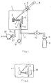
- Fig. 1 is a diagrammatic view showing an apparatus which is applied to the first embodiment of the present invention.
- a substrate 3 is set opposite to a target 2 made of an oxide superconductor or a raw material for the oxide superconductor.
- the target 2 is made of raw materials containing constituent elements for the oxide superconductor, a mixture of power-like raw materials in a proper ratio (for example, the ratio of yttrium, barium and copper is 1:2:3) or a sintered body made by sintering the mixture can be used.
- a beam entry window 7 is provided at the top wall of the evaporation chamber 1 and laser beam 5 is output to a beam generation source, not shown, which is located outside the evaporation chamber 1.
- the laser beam is focused by a lens 6 onto the target 2 via the beam entry window 7.
- a sputtering vapor 4 is emitted from an irradiated portion on the target 2.
- the laser beam 5 may be either pulse-like or continuous.
- An exhaust pipe 19 is provided at the bottom wall of the evaporation chamber 1 such that it is connected via a valve 18 to an exhaust pump 20 by which the interior of the evaporation chamber is exhausted to a desired vacuum level.
- One end of a pipe 11 is connected to the bottom of the evaporation chamber 1 and a nozzle 14 for emitting a jet of excited oxygen molecules extends into the neighborhood of the substrate 3.
- the other end of the pipe 11 is connected to a gas container 8 which contains oxygen, a mixture of oxygen and a gas such as a rare gas, or a gas containing an oxygen compound emitting excited oxygen molecules when it is subjected to a discharge or light irradiation.
- the gas in the gas container 8 is supplied via the pipe 11 to the substrate surface 3.
- a pressure-reducing valve 9 is provided relative to the container 8 and a valve 10 is provided partway of the pipe 11.
- a coil 13 is mounted around that portion of the nozzle 14 which is located near the substrate 3.
- a radio frequency (RF) power supply 12 is connected to the coil 13.
- An oxide superconductor thin film is formed on the aforementioned apparatus as will be set forth below.
- the oxygen gas being supplied toward the substrate is activated by such a discharge into one of atomic oxygen, ozone, and excited oxygen molecules or into a mixture thereof. As a result, oxygen atoms are incorporated into a deposited thin film crystal structure to form an oxide superconductor thin film on the substrate 3.
- the pressure in the evaporation chamber 1 may be above 10 ⁇ 5 Torr (1.33322 x 10 ⁇ 3 Pa), preferably in a range of 0.1 to 1000 m Torr (0.133322 to 133322 x 10 ⁇ 1 Pa) and more preferably about 1 to 100 m Torr (1.33322 to 133.322 x 10 ⁇ 1 Pa).
- the substrate temperature during a thin film deposition step is not particularly limited but, if the substrate needs to be heated, a heater 30 may be provided near the substrate 3 as shown in Fig. 2.
- the atomic oxygen, ozone or excited oxygen molecules can be obtained utilizing not only the aforementioned RF discharge but also a DC discharge, AC discharge and microwave discharge.
- the present invention it is possible to use not only a electrodeless discharge using the aforementioned coil, etc. as well as a discharge using electrodes, silent discharge, microwave discharge using a waveguide, and electron cyclotron resonance.
- the discharge as set out above may be continuous or, if the beam 5 for irradiation is pulse-like, a discharge may be developed in synchronization with the pulse.
- Fig. 3 shows a thin film manufacturing apparatus which evolves excited oxygen by aforementioned silent discharge.
- the apparatus of Fig. 3 is the same as that of Fig. 1 except that the coil 13 of Fig. 1 is replaced with an electrode 22 covered with a dielectric. If a pipe 11 is made of a dielectric such as glass, then it is not necessary to provide the dielectric around the electrode.
- Fig. 4 shows a thin film manufacturing apparatus of a type in which atomic oxygen, ozone or excited oxygen molecules is evolved by a pulse-like DC discharge.
- the apparatus is the same as the apparatus of Fig. 1 except for the oxygen generating mechanism alone. That is, an electrode 24 is provided near a substrate 3 and a DC power supply 23 is connected between the electrode 24 and the substrate whereby a discharge occurs between the electrode 24 and the substrate 3.
- a trigger is supplied from a trigger device 25 to the DC power supply 23 such that it synchronizes with a pulse cycle of a beam 5.
- the trigger signal from the trigger device 25 may be delivered simultaneously with an irradiation beam pulse or either a little before or a little after the irradiation beam pulse.
- Fig. 5 shows a thin film manufacturing apparatus of such a type that atomic oxygen, ozone or excited oxygen molecules is generated by a microwave discharge resulting from an electron cyclotron resonance.
- the apparatus of Fig. 5 is also the that of Fig. 1 except for the oxygen generation mechanism alone. That is, a microwave power supply 26 is provided below a deposition chamber 1 and a waveguide 27 is connected to the power supply 26 such that it extends to the bottom of the deposition chamber 1.
- a discharge tube 28 is located on the bottom of the deposition chamber 1 in a manner to be continuous with the waveguide 27.
- a coil 29 is provided around the discharge tube 28.
- a pipe 11 for oxygen gas supply is connected to the discharge tube 28 to supply an oxygen gas into the discharge tube 28.
- the power supply 26 is operated, for example, in an oxygen gas stream in the discharge tube 28, generating a microwave's discharge in the discharge tube 28 and hence atomic oxygen, ozone or excited oxygen molecules.
- the atomic oxygen, ozone or excited oxygen molecules is supplied to a thin film deposition surface of a substrate 3.
- the coil 29 can be replaced with other magnetic field generators, such as a permanent magnet.
- Fig. 7 is a diagrammatic view showing an apparatus according to the second embodiment of the present invention.
- This apparatus is the same as that of Fig. 1 except that there exists no nozzle.
- the way of supplying atomic oxygen, ozone or excited oxygen molecules is different from that according to the first embodiment of the present invention. That is, in the apparatus shown in Fig. 1, a coil 13 is energized to develop a discharge in an oxygen gas or an oxygen-containing gas of proper pressure in a deposition chamber 1.
- atomic oxygen, ozone or excited oxygen molecules is developed in the neighborhood of a substrate 3 and supplied to a thin film deposition surface of the substrate 3 or near it.
- oxygen atoms are incorporated into a crystal structure of a resultant thin film to form an oxide superconductor thin film.
- the pressure of an O2 gas in the deposition chamber 1 may be 10 ⁇ 5 Torr (1.33322 x 10 ⁇ 3 Pa), but is preferably in a range of 0.1 to 1000 m Torr (0.133322 to 1333.22 x 10 ⁇ 1 Pa) or more preferably in a range of nearly 1 to 100 m Torr (1.33322 to 133.322 x 10 ⁇ 1 Pa).
- a third embodiment of the present invention will be explained below.
- the third and fourth embodiments of the present invention will be explained below in connection with depositing a thin film on the substrate by a CVD method.
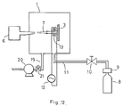
- Fig. 8 is a view showing an apparatus which is applied to the third embodiment.
- a deposition chamber 1 exhaust system, oxygen gas supply system and atomic oxygen, ozone or excited oxygen molecules forming means are given the same reference numerals employed to designate parts or elements corresponding to those shown in Fig. 1, and not explained.
- One end of a pipe 31 is connected to the top surface of a deposition chamber 1 and a gas jet nozzle 34 is connected to the pipe 31 such that it extends toward the neighborhood of a substrate 3.
- a gas container 38 which is held with a feed gas of an oxide superconductor is connected to the other end of the pipe 31.
- a gas in the gas container 38 is supplied to the substrate 3 via the pipe 31.
- a vacuum valve 39 is provided for the container 39 and a valve 40 is provided for the pipe 31.
- a coil 33 is provided around that portion of the nozzle 34 which is situated near the substrate 3.
- An RF power supply 32 is connected to the coil 33.
- air in the deposition chamber 1 is exhausted by a pump 20 and, with electric current flowing from the power supply 32 to the coil 33, a feed gas for oxide superconductor is supplied from the container 38 via the pipe 31 and nozzle 34 onto the surface of the substrate 3.
- a discharge occurs in the feed gas, causing atomic oxygen, ozone or excited oxygen molecules to be produced to allow a corresponding thin film to be deposited on the substrate.
- the oxygen gas or its mixed gas which is jetted from the nozzle 14 is excited with electric current flowing through the coil, supplying it to a thin film deposition site on the substrate 3.
- oxygen atoms are incorporated into a crystal structure of a resultant thin film on the substrate 3. It is thus possible to obtain an oxide superconductor thin film.
- the supply of the feed gas for oxide superconductor and that of an oxygen gas may be alternately or simultaneously carried out.
- the various methods as set out above can be employed, such as a DC discharge or AC discharge. Even in the excitation of the feed gas, various discharging methods can be used as in the case of producing atomic oxygen, ozone or excited oxygen molecules. The aforementioned excitation can be achieved using a light beam and heat.
- organometallic gas is preferable, but the present invention is not restricted thereto. Any material may be used so long as it can be employed as a feedstock for an oxide superconductor.
- the pressure in the deposition chamber 1 is held in a value range as set forth in the first and second embodiments.
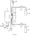
- Fig. 9 is a view showing a diagrammatic arrangement of an apparatus according to a fourth embodiment of the present invention.
- This apparatus is different from that according to the third embodiment in the way of supplying atomic oxygen, ozone or excited oxygen molecules.
- a feed gas for oxide superconductor is supplied from a container 38 via a pipe 31 into a deposition chamber 1 under a proper pressure, while on the other hand a discharge is produced near a substrate 3 with electric current flowing through a coil 13. By doing so, thin film is deposited on the surface of the substrate.
- the feed gas for oxide superconductor is evacuated by a pump 20 and an oxygen gas or mixed gas is supplied from the container 8 via the pipe 11 into the deposition chamber 1 and held in the deposition chamber under a proper pressure.
- the feed gas is excited due to production of a discharge in the neighborhood of the substrate resulting from a flow of electric current through a coil 13.
- atomic oxygen, ozone or excited oxygen molecules is supplied to a thin film deposition spot on the substrate 3.
- oxygen atoms are incorporated into a crystal structure of a resultant thin film to form an oxide superconductor thin film on the substrate.
- An oxide superconductor thin film of a required thickness can be formed on the substrate by repeating the aforementioned two steps a proper number of times.
- the alternate supply of the aforementioned feed gas and oxygen gas is preferable from the standpoint of preventing a possible bad effect caused by a reaction of the oxygen gas with the feed gas.
- the feed gas and oxygen gas if being in coexistence, may simultaneously be introduced into the deposition chamber and converted there to atomic oxygen, ozone or excited oxygen molecules.
- the pressure of the feed gas and oxygen gas in the deposition chamber 1 may be within a range of above 10 ⁇ 5 Torr (1.33322 x 10 ⁇ 3 Pa), preferably within a range of 0.1 to 1000 m Torr (0.1333322 to 1333.22 Pa) and more preferably within a range of about 1 to 100 m Torr (1.333322 to 133.3322 x 10 ⁇ 1 Pa).
- a fifth embodiment of the present invention will be explained below.
- the formation of a thin film on the substrate by an irradiation with a beam containing an oxide superconductor or particles of raw material for the oxide superconductor will be explained below.
- Fig. 10 is a diagrammatic view showing an arrangement of an apparatus as used in a fifth embodiment of the present invention.
- This apparatus is basically similar to that shown in Fig. 7.
- An exhaust system, oxygen gas supply system and atomic oxygen, ozone or excited oxygen molecules forming means in Fig. 12 are the same as those of in Fig. 7.
- a beam emitting device 6 is provided outside a deposition chamber 1, and a substrate 3 set in the deposition chamber 1 is irradiated with a beam which is emitted from the beam emitting device 6 and contains materials for oxide superconductor. Thus, a thin film is formed on the substrate 3.
- atomic oxygen, ozone or excited oxygen molecules is generated near the substrate 3, as in the apparatus shown in Fig. 7, due to the occurrence of a discharge resulting from the flow of electric current through a coil 13.
- the excited oxygen is supplied to or near a thin film deposition site on the substrate 3.
- oxygen atoms are incorporated in a crystal structure of a resultant thin film to form an oxide superconductor thin film on the substrate.
- the pressure of an oxygen gas in the deposition chamber 1 may be within a range of above 10 ⁇ 5 Torr (1.33322 x 10 ⁇ 3 Pa) as in the case of the first to third embodiments, preferably within a range of 0.1 to 1000 m Torr and more preferably within a range of about 1 to 100 m Torr (1.33322 to 133.322 x 10 ⁇ 1 Pa).
- an oxide superconductor thin film pattern can be formed on the substrate by placing a mask pattern on a thin film deposition surface of the substrate in the deposition chamber 1.
- a superconductor thin film can be incorporated into an electronic element with the use of a semiconductor substrate, such as a silicon wafer, and can also be employed to form a wiring layer in the electronic element.
Landscapes
- Chemical & Material Sciences (AREA)
- Engineering & Computer Science (AREA)
- Mechanical Engineering (AREA)
- Chemical Kinetics & Catalysis (AREA)
- Materials Engineering (AREA)
- Metallurgy (AREA)
- Organic Chemistry (AREA)
- General Chemical & Material Sciences (AREA)
- Inorganic Chemistry (AREA)
- Physics & Mathematics (AREA)
- Optics & Photonics (AREA)
- Manufacturing & Machinery (AREA)
- Superconductor Devices And Manufacturing Methods Thereof (AREA)
- Inorganic Compounds Of Heavy Metals (AREA)
- Superconductors And Manufacturing Methods Therefor (AREA)
Claims (25)
- Ein Verfahren zur Herstellung einer Oxidsupraleiter-Dünnschicht, das die Schritte umfaßt, daß:
ein Substrat vorbereitet wird;
eine Oxidsupraleiter-Dünnschicht auf dem Substrat abgelagert wird; und
atomarer Sauerstoff, Ozon oder angeregte Sauerstoffmoleküle einer Dünnschicht-Ablagerungsstelle auf dem Substrat oder in ihre Nähe während der Ablagerung der Dünnschicht zugeführt werden, wobei der atomare Sauerstoff, das Ozon oder die angeregten Sauerstoffmoleküle durch Erzeugen einer Entladung in einem Sauerstoffgas oder einem sauerstoffhaltigen Mischgas erzeugt werden. - Das Verfahren nach Anspruch 1, worin der Ablagerungsschritt ausgeführt wird, indem ein Strahl auf ein Ziel, das Elementarbestandteile eines Oxidsupraleiters enthält, gerichtet wird, um einen mit dem Strahl bestrahlten Zielfleck abzutragen, und verdampfte Materie auf dem Substrat abgelagert wird.
- Das Verfahren nach Anspruch 2, worin der Strahl aus der aus einem Laserstrahl, Elektronenstrahl, Ionenstrahl und Neutralteilchenstrahl bestehenden Gruppe ausgewählt wird.
- Das Verfahren nach Anspruch 2, worin das Ziel einen Oxidsupraleiter oder ein Roh- bzw. Ausgangsmaterial davon enthält.
- Das Verfahren nach Anspruch 1, worin der atomare Sauerstoff, das Ozon oder die angeregten Sauerstoffmoleküle auf eine Dünnschicht-Ablagerungsstelle auf dem Substrat zu oder in ihre Nähe geblasen werden.
- Das Verfahren nach Anspruch 1, worin der atomare Sauerstoff, das Ozon oder die angeregten Sauerstoffmoleküle durch Erzeugen einer Entladung in einem Sauerstoffgas oder einer sauerstoffhaltigen Mischgasatmosphäre in einer Ablagerungskammer erzeugt und der Dünnschicht-Ablagerungsstelle auf dem Substrat oder in ihre Nähe zugeführt werden.
- Das Verfahren nach Anspruch 1, worin die Entladung aus der aus einer Gleichstrom-Entladung, Wechselstrom-Entladung, Hochfrequenz-Entladung und Mikrowellen-Entladung bestehenden Gruppe ausgewählt wird.
- Das Verfahren nach Anspruch 1, worin die Entladung in einer impulsartigen oder kontinuierlichen Weise erzeugt wird.
- Das Verfahren nach Anspruch 2, worin der Strahl eine Substratoberfläche oder ihre Umgebung bestrahlt.
- Das Verfahren nach Anspruch 1, worin der Ablagerungsschritt durch eine Gasphasenabscheidung nach chemischem Verfahren (CVD) ausgeführt wird.
- Das Verfahren nach Anspruch 10, worin der Ablagerungsschritt durch ein Plasma-CVD-, Licht-CVD- oder thermisches CVD-Verfahren ausgeführt wird.
- Das Verfahren nach Anspruch 10, worin der Ablagerungsschritt ausgeführt wird, indem ein Gas, das Elementarbestandteile eines Oxidsupraleiters enthält, angeregt wird, um atomaren Sauerstoff, Ozon oder angeregte Sauerstoffmoleküle auf dem Substrat abzulagern.
- Das Verfahren nach Anspruch 10, worin der atomare Sauerstoff, das Ozon oder die angeregten Sauerstoffmoleküle auf das Substrat zu geblasen werden, um sie dieser Substratoberfläche zuzuführen.
- Das Verfahren nach Anspruch 10, worin der atomare Sauerstoff, das Ozon oder die angeregten Sauerstoffmoleküle durch Erzeugen einer Entladung in einer Gasatmosphäre, die Elementarbestandteile eines Oxidsupraleiters enthält, in einer Ablagerungskammer erzeugt und einer Substratoberfläche zugeführt werden.
- Das Verfahren nach Anspruch 10, worin die Entladung aus der aus einer Gleichstrom-Entladung, Wechselstrom-Entladung, Hochfrequenz-Entladung und Mikrowellen-Entladung bestehenden Gruppe ausgewählt wird.
- Das Verfahren nach Anspruch 12, worin der atomare Sauerstoff, das Ozon oder die angeregten Sauerstoffmoleküle auf ein Substrat zu geblasen werden, um sie einer Substratoberfläche oder in ihre Nähe zuzuführen.
- Das Verfahren nach Anspruch 12, worin der atomare Sauerstoff, das Ozon oder die angeregten Sauerstoffmoleküle durch Erzeugen einer Entladung in einem Sauerstoffgas oder einer sauerstoffhaltigen Gasatmosphäre in einer Ablagerungskammer erzeugt und einer Dünnschicht-Ablagerungsstelle auf einem Substrat oder in ihre Nähe zugeführt werden.
- Das Verfahren nach Anspruch 12, worin die Entladung aus der aus einer Gleichstrom-Entladung, Wechselstrom-Entladung, Hochfrequenz-Entladung und Mikrowellen-Entladung bestehenden Gruppe ausgewählt wird.
- Das Verfahren nach Anspruch 12, worin der Ablagerungsschritt und der Zufuhrschritt für atomaren Sauerstoff, Ozon oder angeregte Sauerstoffmoleküle abwechselnd ausgeführt werden.
- Das Verfahren nach Anspruch 1, worin der Ablagerungsschritt ausgeführt wird, indem ein Strahl, der Elementarbestandteile eines Oxidsupraleiters enthält, zu dem Substrat geleitet wird.
- Das Verfahren nach Anspruch 20, worin der Strahl aus der aus einem Ionenstrahl, Neutralteilchenstrahl, Molekularstrahl, Cluster-Strahl und Cluster-Ionenstrahl bestehenden Gruppe ausgewählt wird.
- Das Verfahren nach Anspruch 20, worin der atomare Sauerstoff, das Ozon oder die angeregten Sauerstoffmoleküle auf ein Substrat zu geblasen werden, um sie einer Dünnschicht-Ablagerungsstelle auf dem Substrat oder in ihre Nähe zuzuführen.
- Das Verfahren nach Anspruch 20, worin der atomare Sauerstoff, das Ozon oder die angeregten Sauerstoffmoleküle durch Erzeugen einer Entladung in einem Sauerstoffgas oder einer sauerstoffhaltigen Gasatmosphäre in einer Ablagerungskammer erzeugt und einer Dünnschicht-Ablagerungsstelle auf einem Substrat oder in ihre Nähe zugeführt werden.
- Das Verfahren nach Anspruch 20, worin die Entladung aus der aus einer Gleichstrom-Entladung, Wechselstrom-Entladung, Hochfrequenz-Entladung und Mikrowellen-Entladung bestehenden Gruppe ausgewählt wird.
- Das Verfahren nach Anspruch 20, worin die Entladung in einer impulsartigen oder kontinuierlichen Weise erzeugt wird.
Applications Claiming Priority (3)
| Application Number | Priority Date | Filing Date | Title |
|---|---|---|---|
| JP6030888 | 1988-03-16 | ||
| JP60308/88 | 1988-03-16 | ||
| PCT/JP1989/000277 WO1989008605A1 (en) | 1988-03-16 | 1989-03-15 | Process for producing thin-film oxide superconductor |
Publications (3)
| Publication Number | Publication Date |
|---|---|
| EP0431160A4 EP0431160A4 (de) | 1991-03-18 |
| EP0431160A1 EP0431160A1 (de) | 1991-06-12 |
| EP0431160B1 true EP0431160B1 (de) | 1995-05-17 |
Family
ID=13138402
Family Applications (1)
| Application Number | Title | Priority Date | Filing Date |
|---|---|---|---|
| EP89903216A Revoked EP0431160B1 (de) | 1988-03-16 | 1989-03-15 | VERFAHREN ZUR HERSTELLUNG EINES DüNNSCHICHTOXYDSUPRALEITERS |
Country Status (4)
| Country | Link |
|---|---|
| US (3) | US5158931A (de) |
| EP (1) | EP0431160B1 (de) |
| DE (1) | DE68922734T2 (de) |
| WO (1) | WO1989008605A1 (de) |
Cited By (1)
| Publication number | Priority date | Publication date | Assignee | Title |
|---|---|---|---|---|
| DE19631101C2 (de) * | 1996-08-02 | 1999-05-20 | Siemens Ag | Beschichtungsapparatur für oxidische Materialien |
Families Citing this family (37)
| Publication number | Priority date | Publication date | Assignee | Title |
|---|---|---|---|---|
| DE69020409T2 (de) * | 1989-04-10 | 1995-11-16 | Imec Inter Uni Micro Electr | Verfahren zum Aufbringen einer Schicht aus supraleitenden Materialien und geeignete Anordnung. |
| JPH02310363A (ja) * | 1989-05-24 | 1990-12-26 | Mitsubishi Electric Corp | レーザ蒸着装置 |
| US5260267A (en) * | 1989-07-24 | 1993-11-09 | Sumitomo Electric Industries, Ltd. | Method for forming a Bi-containing superconducting oxide film on a substrate with a buffer layer of Bi2 O3 |
| US5571169A (en) | 1993-06-07 | 1996-11-05 | Endovascular Instruments, Inc. | Anti-stenotic method and product for occluded and partially occluded arteries |
| JPH06502450A (ja) * | 1990-10-16 | 1994-03-17 | スーパーコンダクター・テクノロジーズ・インコーポレイテッド | 超伝導膜の現場成長法 |
| US5779802A (en) * | 1990-12-10 | 1998-07-14 | Imec V.Z.W. | Thin film deposition chamber with ECR-plasma source |
| CN1037793C (zh) * | 1992-01-28 | 1998-03-18 | 华中理工大学 | 激光沉积大面积超导膜的方法及其装置 |
| JPH05302163A (ja) * | 1992-04-27 | 1993-11-16 | Sumitomo Electric Ind Ltd | 複合酸化物超電導薄膜の成膜方法 |
| DE4229399C2 (de) * | 1992-09-03 | 1999-05-27 | Deutsch Zentr Luft & Raumfahrt | Verfahren und Vorrichtung zum Herstellen einer Funktionsstruktur eines Halbleiterbauelements |
| JP3255469B2 (ja) * | 1992-11-30 | 2002-02-12 | 三菱電機株式会社 | レーザ薄膜形成装置 |
| GB2300000A (en) * | 1992-11-30 | 1996-10-23 | Mitsubishi Electric Corp | Thin film forming using laser and activated oxidising gas |
| US5733609A (en) * | 1993-06-01 | 1998-03-31 | Wang; Liang | Ceramic coatings synthesized by chemical reactions energized by laser plasmas |
| AU8070294A (en) * | 1993-07-15 | 1995-02-13 | President And Fellows Of Harvard College | Extended nitride material comprising beta -c3n4 |
| KR0168699B1 (ko) * | 1993-09-27 | 1999-02-01 | 사토 후미오 | 여기산소 또는 여기가스의 생성방법 및 공급방법 |
| US5411772A (en) * | 1994-01-25 | 1995-05-02 | Rockwell International Corporation | Method of laser ablation for uniform thin film deposition |
| US5443863A (en) * | 1994-03-16 | 1995-08-22 | Auburn University | Low-temperature oxidation at surfaces using ozone decomposition products formed by microwave discharge |
| US5490912A (en) * | 1994-05-31 | 1996-02-13 | The Regents Of The University Of California | Apparatus for laser assisted thin film deposition |
| DE19510318B4 (de) * | 1995-03-22 | 2004-02-19 | Deutsches Zentrum für Luft- und Raumfahrt e.V. | Verfahren und Vorrichtung zur Herstellung epitaktischer Schichten |
| JP3073906B2 (ja) * | 1995-03-27 | 2000-08-07 | 財団法人国際超電導産業技術研究センター | 超電導デバイスの製造方法 |
| US6652922B1 (en) * | 1995-06-15 | 2003-11-25 | Alliedsignal Inc. | Electron-beam processed films for microelectronics structures |
| JP3704258B2 (ja) * | 1998-09-10 | 2005-10-12 | 松下電器産業株式会社 | 薄膜形成方法 |
| US20010052323A1 (en) * | 1999-02-17 | 2001-12-20 | Ellie Yieh | Method and apparatus for forming material layers from atomic gasses |
| EP1214759A2 (de) * | 1999-08-27 | 2002-06-19 | Alan E. Hill | Elektrischer laser auf jod- und sauerstoff-basis |
| US6826222B2 (en) | 1999-08-27 | 2004-11-30 | Alan E. Hill | Electric oxygen iodine laser |
| US7215697B2 (en) * | 1999-08-27 | 2007-05-08 | Hill Alan E | Matched impedance controlled avalanche driver |
| US6638857B1 (en) * | 2000-03-30 | 2003-10-28 | Triquint Technology Holding Co. | E-beam deposition method and apparatus for providing high purity oxide films |
| US20030054105A1 (en) * | 2001-08-14 | 2003-03-20 | Hammond Robert H. | Film growth at low pressure mediated by liquid flux and induced by activated oxygen |
| US20030157269A1 (en) * | 2002-02-20 | 2003-08-21 | University Of Washington | Method and apparatus for precision coating of molecules on the surfaces of materials and devices |
| JP3910466B2 (ja) * | 2002-02-26 | 2007-04-25 | 独立行政法人科学技術振興機構 | 半導体又は絶縁体/金属・層状複合クラスタの作製方法及び製造装置 |
| US8182862B2 (en) * | 2003-06-05 | 2012-05-22 | Superpower Inc. | Ion beam-assisted high-temperature superconductor (HTS) deposition for thick film tape |
| JP5273495B2 (ja) * | 2005-12-13 | 2013-08-28 | 独立行政法人産業技術総合研究所 | クラスター成膜装置及び成膜方法、並びにクラスター生成装置及び生成方法 |
| KR100772014B1 (ko) * | 2006-07-14 | 2007-10-31 | 한국전기연구원 | 보조 클러스트빔 분사에 의한 고온 초전도막 제조방법,제조장치, 이 방법에 의해 제조되는 고온 초전도막 |
| DE102008028542B4 (de) * | 2008-06-16 | 2012-07-12 | Fraunhofer-Gesellschaft zur Förderung der angewandten Forschung e.V. | Verfahren und Vorrichtung zum Abscheiden einer Schicht auf einem Substrat mittels einer plasmagestützten chemischen Reaktion |
| JP5866815B2 (ja) * | 2011-06-21 | 2016-02-24 | 株式会社アルバック | 成膜方法 |
| RU2508576C1 (ru) * | 2012-07-26 | 2014-02-27 | Федеральное государственное бюджетное образовательное учреждение высшего профессионального образования Поволжский государственный технологический университет | Способ электроискрового формирования тонкопленочной втсп схемы |
| RU2676720C1 (ru) * | 2018-03-28 | 2019-01-10 | Федеральное государственное бюджетное учреждение науки Институт электрофизики Уральского отделения Российской академии наук | Способ вакуумного ионно-плазменного низкотемпературного осаждения нанокристаллического покрытия из оксида алюминия |
| CN112899617B (zh) * | 2019-12-04 | 2023-03-31 | 中微半导体设备(上海)股份有限公司 | 形成耐等离子体涂层的方法、装置、零部件和等离子体处理装置 |
Family Cites Families (17)
| Publication number | Priority date | Publication date | Assignee | Title |
|---|---|---|---|---|
| GB2085482B (en) * | 1980-10-06 | 1985-03-06 | Optical Coating Laboratory Inc | Forming thin film oxide layers using reactive evaporation techniques |
| JPS5773178A (en) * | 1980-10-23 | 1982-05-07 | Hitachi Ltd | Production of oxide |
| JPS63192857A (ja) * | 1987-02-05 | 1988-08-10 | Sumitomo Electric Ind Ltd | 超電導薄膜の作製法 |
| JPS63241823A (ja) * | 1987-03-27 | 1988-10-07 | Nissin Electric Co Ltd | 超電導薄膜の製造方法 |
| JPS63239151A (ja) * | 1987-03-27 | 1988-10-05 | Sumitomo Electric Ind Ltd | 超電導セラミツクスの形成方法 |
| JPS63239742A (ja) * | 1987-03-27 | 1988-10-05 | Matsushita Electric Ind Co Ltd | 薄膜超電導体の製造方法 |
| CA1332324C (en) * | 1987-03-30 | 1994-10-11 | Jun Shioya | Method for producing thin film of oxide superconductor |
| EP0288001B1 (de) * | 1987-04-20 | 1993-01-13 | Nissin Electric Company, Limited | Verfahren zur Herstellung einer supraleitenden dünnen Schicht und Anordnung zu seiner Durchführung |
| DE3886586T2 (de) * | 1987-05-26 | 1994-04-28 | Sumitomo Electric Industries | Verfahren zur Herstellung einer dünnen Schicht aus supraleitendem Mischoxid. |
| JPS6421973A (en) * | 1987-07-16 | 1989-01-25 | Nissin Electric Co Ltd | Device for manufacturing superconductive material |
| JPS6439783A (en) * | 1987-08-06 | 1989-02-10 | Matsushita Electric Ind Co Ltd | Manufacture of superconducting element |
| KR910007382B1 (ko) * | 1987-08-07 | 1991-09-25 | 가부시기가이샤 히다찌세이사꾸쇼 | 초전도 재료 및 초전도 박막의 제조방법 |
| JPH0791152B2 (ja) * | 1987-08-31 | 1995-10-04 | 松下電器産業株式会社 | 超伝導体薄膜の製造方法 |
| CA1338202C (en) * | 1988-02-10 | 1996-04-02 | Robert George Charles | Chemical vapor deposition of oxide films containing alkaline earth metals from metal-organic sources |
| US4882023A (en) * | 1988-03-14 | 1989-11-21 | Motorola, Inc. | Method and system for producing thin films |
| US4874741A (en) * | 1988-04-14 | 1989-10-17 | The Research Foundation Of State University Of New York | Non-enhanced laser evaporation of oxide superconductors |
| JPH04500198A (ja) * | 1988-08-19 | 1992-01-16 | リージェンツ・オブ・ザ・ユニバーシティ・オブ・ミネソタ | オゾンを用いた超電導セラミック酸化物の調製 |
-
1989
- 1989-03-15 US US07/439,388 patent/US5158931A/en not_active Expired - Lifetime
- 1989-03-15 WO PCT/JP1989/000277 patent/WO1989008605A1/ja not_active Application Discontinuation
- 1989-03-15 DE DE68922734T patent/DE68922734T2/de not_active Revoked
- 1989-03-15 EP EP89903216A patent/EP0431160B1/de not_active Revoked
-
1992
- 1992-06-23 US US07/888,627 patent/US5284824A/en not_active Expired - Lifetime
-
1993
- 1993-10-25 US US08/140,398 patent/US5374613A/en not_active Expired - Lifetime
Non-Patent Citations (1)
| Title |
|---|
| Japanese Journal of Applied Physics, Vol. 26, No. 7 (July 1987) (Syntheses of Y-Ba-Cu-O Thin Films of Sapphire Substrates by RF Magnetron Sputtering) p L1199-L1201 * |
Cited By (1)
| Publication number | Priority date | Publication date | Assignee | Title |
|---|---|---|---|---|
| DE19631101C2 (de) * | 1996-08-02 | 1999-05-20 | Siemens Ag | Beschichtungsapparatur für oxidische Materialien |
Also Published As
| Publication number | Publication date |
|---|---|
| DE68922734T2 (de) | 1995-09-14 |
| EP0431160A1 (de) | 1991-06-12 |
| WO1989008605A1 (en) | 1989-09-21 |
| EP0431160A4 (de) | 1991-03-18 |
| US5158931A (en) | 1992-10-27 |
| DE68922734D1 (de) | 1995-06-22 |
| US5374613A (en) | 1994-12-20 |
| US5284824A (en) | 1994-02-08 |
Similar Documents
| Publication | Publication Date | Title |
|---|---|---|
| EP0431160B1 (de) | VERFAHREN ZUR HERSTELLUNG EINES DüNNSCHICHTOXYDSUPRALEITERS | |
| JP3192666B2 (ja) | 酸化物超電導膜の製造方法および装置 | |
| JP2854648B2 (ja) | 酸化物超伝導膜の製造方法 | |
| JPH05320882A (ja) | 蒸着薄膜の作製法 | |
| EP0349341A2 (de) | Verfahren zur Verbesserung und/oder zur Herstellung von supreilentenden Oxiden | |
| JPH0992133A (ja) | プラズマディスプレイパネルの製造方法 | |
| US5731270A (en) | Oxide superconductor and method and apparatus for fabricating the same | |
| EP0433294B1 (de) | Verfahren zur herstellung eines halbleiterelements mit supraleitendem material | |
| JP2007063618A (ja) | 酸化物薄膜成長装置 | |
| JP2742418B2 (ja) | 酸化物超電導薄膜の製造方法 | |
| GB2300000A (en) | Thin film forming using laser and activated oxidising gas | |
| JPH06291375A (ja) | 薄膜超電導体の製造方法及びその製造装置 | |
| JP3452458B2 (ja) | 薄膜形成装置 | |
| JP3169278B2 (ja) | 薄膜形成方法及び薄膜形成装置 | |
| JPH01298007A (ja) | 酸化物系超電導体の製造方法 | |
| JP2848977B2 (ja) | 高温酸化物超伝導体薄膜の製造方法及び製造装置 | |
| JPH03197306A (ja) | 酸化物超電導薄膜を作製する装置および方法 | |
| JPH0818913B2 (ja) | 薄膜超電導体の製造方法 | |
| JPS6034013A (ja) | 固体薄膜の製造方法 | |
| JPH02133316A (ja) | 超伝導材料の製造方法 | |
| JPS6116731B2 (de) | ||
| RU2055421C1 (ru) | Способ изготовления пленок высокотемпературных сверхпроводников в едином вакуумном цикле | |
| JPH07243035A (ja) | 化合物薄膜作製方法および装置 | |
| JP2004002907A (ja) | 酸化ケイ素薄膜の形成方法 | |
| JPH01198469A (ja) | 酸化物超伝導薄膜の製造方法 |
Legal Events
| Date | Code | Title | Description |
|---|---|---|---|
| PUAI | Public reference made under article 153(3) epc to a published international application that has entered the european phase |
Free format text: ORIGINAL CODE: 0009012 |
|
| 17P | Request for examination filed |
Effective date: 19891117 |
|
| AK | Designated contracting states |
Kind code of ref document: A1 Designated state(s): DE FR GB |
|
| 17Q | First examination report despatched |
Effective date: 19920715 |
|
| GRAA | (expected) grant |
Free format text: ORIGINAL CODE: 0009210 |
|
| AK | Designated contracting states |
Kind code of ref document: B1 Designated state(s): DE FR GB |
|
| REF | Corresponds to: |
Ref document number: 68922734 Country of ref document: DE Date of ref document: 19950622 |
|
| ET | Fr: translation filed | ||
| PLBI | Opposition filed |
Free format text: ORIGINAL CODE: 0009260 |
|
| PLBF | Reply of patent proprietor to notice(s) of opposition |
Free format text: ORIGINAL CODE: EPIDOS OBSO |
|
| 26 | Opposition filed |
Opponent name: SIEMENS AG Effective date: 19960126 |
|
| PLBF | Reply of patent proprietor to notice(s) of opposition |
Free format text: ORIGINAL CODE: EPIDOS OBSO |
|
| RDAH | Patent revoked |
Free format text: ORIGINAL CODE: EPIDOS REVO |
|
| APAC | Appeal dossier modified |
Free format text: ORIGINAL CODE: EPIDOS NOAPO |
|
| APAE | Appeal reference modified |
Free format text: ORIGINAL CODE: EPIDOS REFNO |
|
| APAC | Appeal dossier modified |
Free format text: ORIGINAL CODE: EPIDOS NOAPO |
|
| REG | Reference to a national code |
Ref country code: GB Ref legal event code: 746 Effective date: 19981008 |
|
| REG | Reference to a national code |
Ref country code: FR Ref legal event code: D6 |
|
| PGFP | Annual fee paid to national office [announced via postgrant information from national office to epo] |
Ref country code: DE Payment date: 19991231 Year of fee payment: 12 |
|
| PGFP | Annual fee paid to national office [announced via postgrant information from national office to epo] |
Ref country code: GB Payment date: 20000315 Year of fee payment: 12 |
|
| APAC | Appeal dossier modified |
Free format text: ORIGINAL CODE: EPIDOS NOAPO |
|
| RDAG | Patent revoked |
Free format text: ORIGINAL CODE: 0009271 |
|
| STAA | Information on the status of an ep patent application or granted ep patent |
Free format text: STATUS: PATENT REVOKED |
|
| 27W | Patent revoked |
Effective date: 20000503 |
|
| GBPR | Gb: patent revoked under art. 102 of the ep convention designating the uk as contracting state |
Free format text: 20000503 |
|
| PGFP | Annual fee paid to national office [announced via postgrant information from national office to epo] |
Ref country code: FR Payment date: 20040309 Year of fee payment: 16 |
|
| APAH | Appeal reference modified |
Free format text: ORIGINAL CODE: EPIDOSCREFNO |