EP0418699A1 - Appareil d'étanchéité de joints de reprise de bétonnage et procédé pour remplir l'appareil - Google Patents
Appareil d'étanchéité de joints de reprise de bétonnage et procédé pour remplir l'appareil Download PDFInfo
- Publication number
- EP0418699A1 EP0418699A1 EP90117399A EP90117399A EP0418699A1 EP 0418699 A1 EP0418699 A1 EP 0418699A1 EP 90117399 A EP90117399 A EP 90117399A EP 90117399 A EP90117399 A EP 90117399A EP 0418699 A1 EP0418699 A1 EP 0418699A1
- Authority
- EP
- European Patent Office
- Prior art keywords
- sealing device
- sealing
- profile
- concrete surface
- concrete
- Prior art date
- Legal status (The legal status is an assumption and is not a legal conclusion. Google has not performed a legal analysis and makes no representation as to the accuracy of the status listed.)
- Granted
Links
Images


Classifications
-
- E—FIXED CONSTRUCTIONS
- E04—BUILDING
- E04B—GENERAL BUILDING CONSTRUCTIONS; WALLS, e.g. PARTITIONS; ROOFS; FLOORS; CEILINGS; INSULATION OR OTHER PROTECTION OF BUILDINGS
- E04B1/00—Constructions in general; Structures which are not restricted either to walls, e.g. partitions, or floors or ceilings or roofs
- E04B1/62—Insulation or other protection; Elements or use of specified material therefor
- E04B1/66—Sealings
- E04B1/68—Sealings of joints, e.g. expansion joints
-
- E—FIXED CONSTRUCTIONS
- E02—HYDRAULIC ENGINEERING; FOUNDATIONS; SOIL SHIFTING
- E02D—FOUNDATIONS; EXCAVATIONS; EMBANKMENTS; UNDERGROUND OR UNDERWATER STRUCTURES
- E02D29/00—Independent underground or underwater structures; Retaining walls
- E02D29/16—Arrangement or construction of joints in foundation structures
-
- E—FIXED CONSTRUCTIONS
- E04—BUILDING
- E04B—GENERAL BUILDING CONSTRUCTIONS; WALLS, e.g. PARTITIONS; ROOFS; FLOORS; CEILINGS; INSULATION OR OTHER PROTECTION OF BUILDINGS
- E04B1/00—Constructions in general; Structures which are not restricted either to walls, e.g. partitions, or floors or ceilings or roofs
- E04B1/62—Insulation or other protection; Elements or use of specified material therefor
- E04B1/66—Sealings
- E04B1/68—Sealings of joints, e.g. expansion joints
- E04B1/6812—Compressable seals of solid form
-
- E—FIXED CONSTRUCTIONS
- E04—BUILDING
- E04B—GENERAL BUILDING CONSTRUCTIONS; WALLS, e.g. PARTITIONS; ROOFS; FLOORS; CEILINGS; INSULATION OR OTHER PROTECTION OF BUILDINGS
- E04B1/00—Constructions in general; Structures which are not restricted either to walls, e.g. partitions, or floors or ceilings or roofs
- E04B1/62—Insulation or other protection; Elements or use of specified material therefor
- E04B1/66—Sealings
- E04B1/68—Sealings of joints, e.g. expansion joints
- E04B1/6813—Compressable seals of hollow form
-
- E—FIXED CONSTRUCTIONS
- E04—BUILDING
- E04B—GENERAL BUILDING CONSTRUCTIONS; WALLS, e.g. PARTITIONS; ROOFS; FLOORS; CEILINGS; INSULATION OR OTHER PROTECTION OF BUILDINGS
- E04B1/00—Constructions in general; Structures which are not restricted either to walls, e.g. partitions, or floors or ceilings or roofs
- E04B1/62—Insulation or other protection; Elements or use of specified material therefor
- E04B1/66—Sealings
- E04B1/68—Sealings of joints, e.g. expansion joints
- E04B1/6816—Porous tubular seals for injecting sealing material
Definitions
- the invention relates to a sealing device for concrete joints according to the preambles of claims 1 and 33 and a method for introducing a sealing medium into sealing devices, as described in claim 49.
- a sealing device in the form of a porous tube is known from CH-PS 600 077.
- This hose consists of a support body in the form of a helical spring, which is surrounded by a first, braided hose, which in turn is surrounded by an outer, mesh-like, porous hose.
- the sealing device according to DE-GM 83 35 231 tries to remedy the disadvantage of the hose body becoming blocked by introducing a non-woven material between the support body in the form of a helical spring and the outer network-like hose, which material is permeable to liquid but impermeable to fine concrete particles .
- sealing medium is pressed directly into the beginning or end of the hose.
- the start and end of the hose must be freely accessible from the outside after completion of the concreting measures in the joint area.
- sealing medium can be introduced into sealing devices, in particular of the proposed type, in a simple, safe and inexpensive manner.
- the proposed sealing device is completely detached from the previous use of hose-like sealing devices and suggests the use of a profile which is open in cross-section and is hood-shaped.
- the profile is mounted with the free longitudinal edges of its side areas or side walls seated on the concrete surface, so that the free passage or flow channel is formed between the profile and the concrete surface, the sealing medium between the free longitudinal edges of the profile and the concrete surface in the joint area can leak.
- profiles can be produced quickly and inexpensively by injection or extrusion and can be laid in a simple manner will.
- silicates or hardening one- or multi-component plastics in liquid consistency are used as the sealing medium.
- Synthetic resin in particular 2-component acrylic resin, is also used as a sealing medium, as are bentonite and / or cement mixtures.
- the profile seen in cross section, is a U-shaped profile with a top wall and two side walls extending vertically therefrom.
- the stackability of the profiles during storage can be improved in that the profiles have a trapezoidal or arched cross section.
- An advantageous fastening of the profile is carried out by one or more screws, pins or nails, which encompass the transverse axis of the profile and encase it in the concrete.
- the fastening of the profiles can preferably be increased in that the screw or the nail is supported by their heads, preferably via a washer, on the ceiling area or the ceiling wall of the profile, with the shaft reaching through a hole in the ceiling wall and into the concrete surface , if necessary, enclose in a dowel inserted therein.
- a quick assembly of the profile is advantageously possible by shooting in the pin or the nail.
- Supporting the ceiling wall is made possible by clamping the ceiling wall between the head and the shaft.
- the clamping is preferably carried out via a lock nut on the screw, pin or nail.
- Another advantageous way of supporting the ceiling wall is via a spacer, which is between the concrete surface che and the inner surface of the ceiling wall is arranged.
- the production of the profiles is also particularly favorable because the entire profile consists of one and the same material.
- sealing lips preferably in one piece, can also be formed on the longitudinal edges, which also facilitate the escape of the sealing medium.
- the sealing lips are preferably elastic, in particular made of soft plastic or rubber or the like, which also facilitates the escape of the sealing medium.
- the profiles can also be attached to the concrete surface in the area of the web surface using suitable holding means.
- the interior of the profile is filled with an open through-pored plastic foam (filter foam), the sealing medium in the flow channel being conductive through the through-pores of the plastic foam.
- the plastic foam also supports the cross-sectional shape of the profile and ensures that the consumption of the sealing medium used is significantly reduced.
- the plastic foam is chosen so that it has enough large and large passage pores to prevent the sealing medium from entering not to hinder and even prevent.
- the interior of the profile can also be foamed with plastic foam or a plastic foam strip can be fitted into the interior.
- the interior can be filled quickly and inexpensively with the plastic foam.
- the plastic foam or the plastic foam strip advantageously has a protrusion beyond the longitudinal edges of the profiles. This protrusion ensures an enlarged cross section of the sealant from the profile.
- a free passage channel is provided in the longitudinal direction of the profile below the ceiling wall with a bottom wall arranged approximately in the middle of the height of the side walls, which has a longitudinal slot or similar passages, the flow channel being filled with plastic foam below the bottom wall.
- This configuration of the profile forms a free flow channel in which the sealing medium can initially enter and distribute unhindered, and then exit through the longitudinal cut into the plastic foam and from there into the joint area.
- the passage channel can preferably also be formed in that a groove running in the longitudinal direction of the profile is arranged in the inner surface of the profile facing the flow channel, preferably in the inner surface of the ceiling wall.
- connecting elements having the same cross-sectional shape of the profiles, preferably also made of plastic, are provided. With the help of such connecting elements, the profiles can be placed in any direction on the concrete surface che be arranged.
- the connecting elements are preferably straight connecting pieces, flat corner angles, upright corner angles, T-pieces or crossing pieces. With the help of the proposed connecting elements, the most important changes in direction can be made when laying the profiles.
- the connecting elements can be slipped onto the profiles and are preferably held thereon in a positive and non-positive manner.
- the connection of the individual profiles via the connecting elements is thus carried out in a simple manner and the proposed connection ensures that no sealing medium can emerge from the profiles in the joint area.
- the connecting elements can advantageously be screwed onto the concrete surface together with the profiles. Thus, only a bracket for profile and connecting element must be used at the joint.
- an impermeable adhesive tape is provided at the joints to prevent cement slurries and other particles from entering the profiles in the joint area during the concreting process and on the other hand the sealing medium escaping from the ceiling and side wall area. since it is actually not needed there.
- the adhesive tape is applied in the ceiling and side wall area of the joint and can also end before the free longitudinal edges are closed, since increased emergence in the lower area of the side walls may well be desirable.
- the butt joints can preferably also be welded.
- the profile or the connecting elements for injecting the sealing medium have a connection, in particular in the form of a tube or a non-porous hose, which with its free end is arranged outside the joint area or a formwork. Accordingly, certain elements of the sealing device can already be provided with such a connection, so that such a connection point no longer has to be created on site.
- the method for introducing the sealing medium described later can be used with particular advantage.
- the profiles or connecting elements in the side walls have notches with their corners or notch tips on the ceiling wall or just before the ceiling wall end up.
- the profiles or connecting elements are bent around their longitudinal axis and fastened on a curved concrete surface or on an arched or circular body, for example a pipe, the side edges of the notches abutting one another and the notches thus being closed, if the longitudinal edges of the side walls lie on the concrete surface or the body.
- the sealing device can be arranged not only on curved concrete surfaces, but even on curved or circular bodies. It is important that the notches are completely closed when the longitudinal edges lie against the concrete surface or the surface of the corresponding body.
- the notches can also be sealed with an adhesive tape.
- An advantageous way of fastening the profile is that the profile and / or a connecting elements are held by a tubular clamp-shaped bracket.
- the attachment for example to a reinforcement bar, is preferably carried out by the bracket at the free end of itself approximately parallel or slightly inclined to the concrete surface extending arm has a plug-in device for plugging, for example on a reinforcing bar.
- the plug-in device is formed by a bending of the holding arm by approximately 360 ° with an oblique course, preferably to the side of the support arm formed in this way, the side facing away from the profile to be held, the bending diameter and the distance of the starting area from the end area of the bend being greater than the diameter of the reinforcing bar.
- the proposed holding device can thus be arranged safely and immovably in a simple manner.
- the spring clip is preferably made of elastically bendable material, in particular spring steel, in order to be able to compensate for any tolerances.
- the bracket is bent from round wire, which can be easily and easily brought into the desired shape.
- the sealing device consists of a preferably cross-sectionally rectangular body made of a passage pores foam (filter foam) or a foam tape, which is placed on the concrete surface and mounted there, so that the passage or flow channel through the body itself is formed and that Sealing medium emerges from the passage pores into the joint area.
- a passage pores foam filter foam
- a foam tape which is placed on the concrete surface and mounted there, so that the passage or flow channel through the body itself is formed and that Sealing medium emerges from the passage pores into the joint area.
- the body can also have other shapes, for example a trapezoidal shape or a curved or a circular segment shape.
- the fact that the sealing medium A high degree of sealing in the area of the concrete joint is achieved not only in the area of the contact area of the foam tape in the joint area, but also from its side and ceiling area.
- a hose-like hollow body can be provided as the inlet opening for the sealing medium, for example, which is inserted into the body at one end and is arranged at the other end outside the second concreting section or its formwork.
- the method for introducing the sealing medium described later can be used with particular advantage.
- the foam or the foam tape used on the one hand has sufficient porosity for the passage of the sealing medium and on the other hand is of a consistency that largely avoids compression of the foam or the foam tape by the applied concrete.
- silicates or hardening single- or multi-component plastic in liquid consistency are used as sealing medium.
- Synthetic resin, in particular 2-component acrylic resin, is also used as a sealing medium, as are bentonite and / or cement mixtures.
- the body is advantageously fastened to the concrete surface by means of one or more pins, screws or nails which extend transversely to its longitudinal axis and surround the concrete and preferably have washers.
- the introduction of dowels in the concrete surface or by a predetermined setting of shooting devices ensures that the above-mentioned holding means only engage in the concrete surface to such an extent that their head region lies approximately in a plane with the surface of the body after the introduction.
- the desired end position of the pins, screws or nails can be achieved by using tubular spacers which encompass the holding means, the length of the spacers being approximately the cross-sectional height of the body corresponds. The spacer then ensures that the holding means do not penetrate too deep into the body.
- Another preferred mounting of the body can also be carried out by mounting profiles comprising it, which are mounted on the concrete surface.
- the support profiles can be metal or plastic straps that completely or partially encompass the cross-sectional circumference of the body, the support profiles being arranged with a free end on the concrete surface, so that the support device holds or clamps the body on the concrete surface without significantly reducing the cross section of the body at the bus stop.
- a continuous recess running in the longitudinal direction can be provided in the cross-sectional interior of the body and serves as a through-channel for the sealing medium.
- the through-channel is first filled and then the sealing medium penetrates the body until it emerges into the concrete area, closing off the existing joints.
- connection of at least two bodies on the abutting edges of the same is advantageously carried out by the same cross-sectional shape and made of the same material connecting elements.
- These connecting elements can be straight connecting pieces, flat corner brackets, upright corner brackets, T-pieces or crossing pieces, so that changes in direction can be easily taken into account when laying the body.
- An adhesive tape is preferably provided to connect the bodies to one another or the body to the connecting elements at the joints.
- the tape is used primarily for Securing the position of the body and can preferably be attached only on the side of the body facing away from the concrete surface and in the upper region of the side parts of the body, so that sufficient sealing material can escape even at the joint, despite adhesive tape.
- V-shaped, notch-like incisions are provided, extending over their entire cross-sectional width, the notch tips slightly below that Cross-sectional height of the body or the connecting elements are arranged.
- the notch-like incisions should therefore only be made to such an extent that the body still forms a coherent body.
- the bodies or fasteners are bent about their longitudinal axis and secured on a curved concrete surface or on an arc or circular element, for example a pipe, the side edge surfaces of the notches abutting one another and the notches thus being closed when the underside of the body is on the Concrete surface or the element.
- the foam strips can also follow curved or curved courses.
- the bodies or connecting elements are also advantageously possible to bend the bodies or connecting elements about their longitudinal axis in order to fix them on a curved concrete surface or on an arcuate or circular element, for example a pipe, without providing notch-like incisions.
- the body consisting of the foam or filter foam will compress in the area facing the curved or curved surface, but this compression does not prevent the sealing material from escaping. This is because the material intended for the body is of such a nature is that even with a stronger compression of the material, the passage pores required for the passage of the sealing medium are still present.
- the bodies and / or connecting elements are advantageously held on the circular element with an endless rubber band, in that the rubber band is stretched over the top of the bodies or connecting elements.
- This simple and quick way of fastening the body and / or the connecting elements ensures a firm fit on circular or curved elements without having to use other mounting means.
- the rubber bands can preferably have a cross-sectional width that is smaller or substantially smaller than the cross-sectional width of the body or bodies, so that leakage of the sealing medium is also not significantly hindered on the top of the body.
- the body has on its top surface facing away from the concrete surface and its side surfaces a type of coating or coating of harder foam, which is preferably impermeable to the sealing medium, the coating in the area of the Side surfaces preferably end in front of the underside or standing surface of the body, so that the through-pored foam or filter foam in the lower side areas is without the coating.
- the body should therefore have a second, outer layer by means of the additional coating to be arranged in parts of its side areas and above all on its surface, which on the one hand represents a support effect for the body and on the other hand a leakage of the sealing medium injected into the body from the Prevents areas that have the coating.
- the sealing medium should in particular seal the joint area, ie the area of the base of the body. Because the coating in the side areas is not up to the footprint of the body is pulled down, but ends in front of this and thus in front of the concrete surface, a sufficiently large exit surface for the sealing medium is created in the lower side areas in the standing area of the body.
- the coating can be applied subsequently to the body or can be produced together with the body. It does not matter whether the body, seen in cross section, has a linear side edge or a crack due to the application of the coating.
- the foam or the filter foam of the body is of a material which prevents the body from being compressed too much, even at high pressures, so that there is always a sufficiently large outlet space for the sealing medium.
- the body according to the invention consisting of foam or foam tape, is advantageously used for sealing a groundwater relief connection.
- Groundwater relief ports which penetrate floor slabs, for example, with the groundwater level above the level of the floor slab, are wrapped or wrapped around the body at the base plate / discharge port connection point, so that after the sealing medium has been introduced into the body, a secure seal against rising groundwater at the aforementioned connection point is guaranteed.
- the proposed body can advantageously be used to seal a joint area between a body, for example a pipe, and a concrete section, in particular if liquids are constantly or occasionally present on one side of the concrete section.
- a body for example a pipe
- a concrete section in particular if liquids are constantly or occasionally present on one side of the concrete section.
- water-filled concrete pools in the concrete walls have pipe openings or other devices, such as headlights or the like, whereby the joint area between the concrete walls and the bodies used therein must be carefully sealed in order to prevent water from penetrating into this area with the proposed Body and a subsequent injection of the sealant can be done safely and reliably.
- the proposed body can be used to seal a connection point between two pipes, even with a pipe socket connection point.
- the body is arranged in the area of the gap between the two pipes connected to one another by being placed around this area and forming a ring around the connection point, as in the relief connection. After the sealing medium has been introduced into the body, the connection point is secured in such a way that any escaping liquid can be safely retained from the connection point.
- An essential basic idea here is the knowledge that one or more external connections for introducing the sealing medium, which are arranged outside the second concreting section or the formwork, can be dispensed with, i.e. the sealing device without a connection to the outside in the joint area between the two concreting sections is arranged.
- All previously known sealing devices and in particular the sealing devices according to claims 1 and 33 can be filled with a sealing medium by a subsequent connection between an outside of the concrete or the second concreting section and the sealing devices.
- the sealing medium is e.g. for silicates or hardening one- or multi-component plastics in liquid or compressible consistency.
- Synthetic resin, in particular 2-component acrylic resin can also be used as a sealing medium, as can bentonite and / or cement mixtures.
- connection is made, for example, in particular by drilling into the hardened concrete between an outer sieve te of the concrete and the sealing devices. It goes without saying that the bore must be made so far that the flow channel or the passage of the sealing device is accessible.
- the sealing medium is then introduced or pressed in through the connection or the borehole.
- a further connection to the sealing device is advantageously created, through which the air can escape during the press-in process and which also serves as a control point as to whether the sealing medium has also penetrated the entire sealing device. It is also conceivable to create a larger number of such connections and then to seal them when the sealing medium emerges from the connection points.
- connection points serving as control points should be arranged at the beginning or at the end of the joint in order to check that the sealing medium also extends into the end regions of the sealing device has penetrated.
- connection can be made horizontally or from obliquely above or obliquely below in the direction of the sealing device.
- the connection points are preferably made at predetermined positions, it being possible to determine beforehand at what height or at what angle and above all how long the connection point must be created, in order to ensure that the sealing device is also hit or drilled in the desired manner .
- the proposed method for introducing the sealing medium into sealing devices prevents the formwork from having one or more openings for previously laid connection openings or connecting pieces. It also prevents these previously created connection points from being torn or destroyed during formwork or concreting.
- the load-bearing capacity or safety of the pierced concrete is not reduced by the arrangement of several connection points.
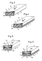
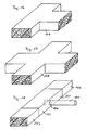
- the plastic profile 2 is mounted on the concrete surface 1 such that the free longitudinal edges 5 of the side walls 3 sit on the concrete surface 1, so that a flow channel 6 between the concrete surface che 1 and the profile 2 is formed.
- the profile 2 can be fastened to the concrete surface 1 using brackets or the like.
- a simple screw connection is preferably provided, in which a screw 7 is supported with its screw head 8, possibly via a washer (not shown), on the ceiling wall 4, with its shaft engages through a hole in the ceiling wall 4 and e.g. is screwed into a dowel arranged in the concrete.
- a pin or nail (not shown) can also be used, which is hammered into the concrete or shot in by means of a shooting device, the pin or nail also being able to secure the profile 2 with or without a head. The latter in particular when he grips the profile 2 (shoots through).
- the sealing device according to the invention is thus fixed in place and cannot be displaced by the fresh concrete of the second concreting section.
- the profile 2 is made sufficiently stiff that it is not deformed or crushed deleteriously by the fresh concrete applied or by the action of the forces occurring when using a concrete vibrator.
- the sealing medium is introduced, which can not escape through the walls of the profile 2, because its walls are impermeable to the sealing medium.
- the sealing medium can penetrate to the outside between the longitudinal edges 5 of the profile 2 and the concrete surface 1, sealing in the respective environment, in each case in the areas of the wall connection points or the connection points of the profile 2, leaky areas or areas capable of receiving the sealing medium.
- the roughness of the concrete surface is usually sufficient to provide enough cut-out points for the sealing medium.
- FIG. 2a shows a profile 42 with a trapezoidal cross section
- the profile 52 shown in FIG. 2b has an arcuate cross section.
- the two profiles 42, 52 and the additional arrangement of the sealing lips shown in FIG. 2 are fastened in an analogous manner.
- the advantage of the cross-sectional shapes of the profiles 42, 52 can be seen, inter alia, in the fact that profiles 42, 52 designed in this way are substantially increased in stackability, so that space for storage can be saved.
- the side walls 43 and 53 can consist of a more elastic material than the corresponding ceiling walls 44 and 54.
- a profile with a U-shaped cross section is always shown as an exemplary embodiment. It should be noted at this point that the advantageous configurations, which are explained in the following figures, can also be used for other cross-sectional shapes of the profile, in particular for the cross-sectional shapes of the profiles 42, 52.
- the flow channel 6 is in each case foamed with a plastic strip or a plastic foam 10 which has open passage pores, so that the sealing medium in the flow channel 6 is passed through the passage pores of the plastic foam 10.
- a profile 12 can expediently be used, into which the plastic foam in the form of a plastic foam strip is fitted, preferably glued.
- An overhang 10a is advantageous in which the plastic foam 10 or the plastic foam strip protrudes beyond the longitudinal edges 5 of the profile 12. The projection 10a ensures that the longitudinal edges 5 on the concrete surface 1 are slightly spaced remain so that a larger amount of sealing medium can escape in this area.
- the plastic foam may compress somewhat in the region of the protrusion 10a, but the longitudinal edges of the profile 12 will still be spaced apart from the concrete surface 1.
- a profile 12 filled in this way can also be provided with sealing lips 9 with or without an overhang 10a. Larger unevenness of the concrete surface 1 can also be compensated with the protrusion 10a or the sealing lips 9, so that a particularly smooth or flat concrete surface 1 is not required before the sealing device is installed.
- FIGS. 5 and 6 A variant of the sealing device is shown in FIGS. 5 and 6, wherein in the longitudinal direction of the profile 22 below the ceiling wall 4 a free through channel 6a is provided with a bottom wall 11 arranged approximately in the middle of the height of the side walls 3 and having a longitudinal slot 13 .
- the flow channel 6 is foamed with a plastic foam 10 or has a plastic foam strip, as is also shown in FIGS. 3 and 4.
- an overhang 10a of the plastic foam 10 or the plastic strip and / or a sealing lip 9 can be provided.
- a slot 13 or in combination with a slot 13 holes or similar openings can also be provided in the bottom wall 11.
- the sealing medium is first introduced or pressed or pressed into the passage 6a and passes through the slots 13 or holes provided in the bottom wall 11 into the plastic foam 10 in the flow channel 6 and from there under the longitudinal edges in the for the sealing medium receptive and to be sealed area in the joint between the first and second concreting section, for example a wall connection.
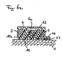
- Fig. 6a shows in cross section a further alternative of a profile 62.
- the through channel 6a is formed in that in the inner surface of the ceiling wall 4 facing the flow channel 6 there is arranged a groove running in the longitudinal direction of the profile 62, which is the free through channel 6a.
- the sealing medium is first introduced into this free passage 6a.
- the provided plastic foam 10 is impregnated with the sealing medium and then emerges in the region of the free longitudinal edges 5 in the desired manner.
- a web 46 can be provided as a horizontal extension of the side wall 3, a foam tape 47 being provided below the web, facing the concrete surface 1. This foam tape 47 is compressed somewhat when the profile 62 is fastened, but remains porous enough so that the sealing medium can escape through the foam tape 47 at the free end.
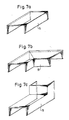
- the proposed sealing device is of a particularly simple construction and should therefore also provide correspondingly simple connecting elements between the abutting edges of two profiles 2, 12, 22, 42, 52, 62.
- Connecting elements can be connected, the dimensions of which are selected such that they can be put onto the profiles 2, 12, 22, 42, 52, 62 for example in a form-fitting and / or non-positive manner.
- FIG. 7a to 7e illustrate that straight connecting pieces 14 (FIG. 7a), flat corner brackets 15 (FIG. 7b), upright corner brackets 16 (FIG. 7c), T-pieces 17 (FIG. 7d), crossing pieces 18 ( 7e) are usable.
- the connecting elements can be fastened in the manner described above by means of screws, pins, nails or the like, preferably together with the profiles 2, 12, 22, 42, 52, 62 on the concrete surface 1 or on the profiles 2, 12, 22, 42, 52, 62 glued or held on it with locking means.
- connection elements are selected which have exactly the shape of the profiles 2, 12, 22, 42, 52, 62 in their cross-sectional shape.
- the profiles 2, 12, 22, 42, 52, 62 are then simply attached to the connecting elements, i.e. laid with them on bump.
- the connection point imaginable as a cross section can then simply be covered with an adhesive tape, so that the sealing device is prevented from slipping.
- the individual profiles 2, 12, 22, 42, 52, 62 and the connecting elements can be fastened in the usual manner.
- the adhesive tape can also be guided in multiple layers over the joint, the adhesive tape should extend up to the area of the free longitudinal edges 5 at the joint or shortly before. It is not recommended to completely wrap the joint or joint, as this would prevent the sealant from escaping in this area.
- Fig. 8 shows that for a particularly simple connection point for the pressing of the sealing medium in the sealing device, the abutting edge 19 of two profiles 2, 12, 22 can be arranged at a distance and that the dimensions of the profiles 2, 12 over the abutting edge region , 22 adapted press-in connector 23 is set in a form-fitting and / or non-positive manner, which can have, for example, the three-dimensional shape of the connecting piece 14, a movable, load-bearing, non-porous hose 21 being arranged on a hole 24 or, for example on a side wall 20 of the press-in connector 23 a connecting piece attached there is used, which is located in the area between the Butt edges 19 is located.
- profiles 42, 52, 62 can have a connection point designed according to FIG. 8, and that it is in particular also possible to use profiles 2, 12, 22 shown to be abutted directly onto the press-in connector 23 if the press-in connector 23 has the cross-sectional shape of the profiles 2, 12, 22 in an identical manner.
- the profiles 2, 12, 22 can be laid not only on flat surfaces 1, but also on curved or curved or round surfaces, e.g. of pipes or tubes which are surrounded or wrapped like a sleeve with the profiles 2, 12, 22.
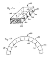
- notches 25 are punched out of the side walls 3 of the profiles 2, 12, 22 or are omitted in the shaping of the profiles 2, 12, 22, which end with their notch tips 26 on the top wall 4 or shortly before the top wall 4, such as this is shown in Fig. 9a.
- Such a profile 2, 12, 22 can, according to FIG. 9b, be bent at least into an arc, preferably into a ring (not shown), because the material of the profiles 2, 12, 22, which preferably consists of plastic, is sufficiently flexible.
- the profile 2, 12, 22 is placed against the jacket surface, for example a pipe (not shown), and is bent accordingly and fastened on the pipe. It is expediently provided that the side edges 27 of the notches 25 abut against one another.
- a second concreting section is then concreted in the area of the profiles 2, 12, 22 around the pipe.
- the sealing medium is then fed into the interior of the profiles 2, 12, 22 via supply means (not shown), from which it can penetrate under the longitudinal edges 5 and / or through the abutting edge slots of the notches 25 into receivable cavities.
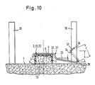
- the profiles 2, 12, 22, 42, 52, 62, the connecting elements 7a to 7e and the press-in connector can advantageously also be held on the concrete surface 1 by means of a bracket 31, a clamping bracket preferably being used which has a certain prestress against the profiles 2 , 12, 22, 42, 52, 62 or the connecting elements 7a to 7e or the press-in connector and thus prestressing them against the concrete surface 1.
- a bracket 31 can be designed in the form of a conventional pipe clamp, so that there is also a lateral fixation.
- the bracket 31 can be fastened to the concrete or to the concrete surface 1 by means of a fastening element encompassing its fastening tab, in particular a washer, a pin or a nail - as shown or described for the fastening for the profiles 2, 12, 22.
- a bracket holder is preferred, in which the bracket 31 is secured by inserting it into a form-fitting holder.
- An exemplary embodiment of this is shown in FIG. 10, the profiles 2, 12, 22 being shown by way of example, but the other profiles 52, 42, 62, the connecting elements 7a to 7e and the press-in connector 23 can also be secured in the same way.
- the bracket 31 engages over the profile 2, 12, 22 in the form of a pipe clamp and is bent approximately at the end of its bracket for this purpose so that the profile 2, 12, 22 is also held laterally.
- a holding arm 33 From the U-shaped mounting part 32 extends at a distance a from the concrete surface 1 horizontally or somewhat inclined, a holding arm 33 which continues into a support arm 34 which wraps around a reinforcing bar 35 extending here perpendicular to the concrete surface 1 and, preferably obliquely to Holding arm 33 extending, which, the profile 2,12,22 facing side of the reinforcing bar 35 also wraps. So the one across Wrap points 36, 37 having a distance b from one another to the concrete surface 1 represent abutments which secure the bracket 31 against lifting off from the profile 2, 12, 22.
- the bracket 31 is made of an elastic material, in particular spring steel, the holding and supporting arm 33, 34 being arranged at such a distance from the concrete surface 1 and the reinforcing bar 35 that the holding arm 33 is prestressed against the concrete surface 1.
- a distance c is provided between the end part 38 of the support arm 34 and the holding arm 33, which is greater than the cross-sectional dimension or the diameter of the reinforcing bar 35. This configuration makes it possible to thread the support arm 34 into the illustrated mounting point by reaching around and tilting it.
- the bracket 31 is preferably made of a round wire.
- the sealing device or the profile 2, 12, 22 is preferably arranged centrally between the reinforcing bars 35 shown. It is thus possible, alternatively or alternatively, to hold the same bracket 31 on the reinforcing bar 35 shown on the left in FIG. 10 in a positive and / or non-positive manner.
- FIG. 11 An alternative sealing device according to the invention is shown in FIG. 11, wherein a body 102 made of foam or a foam tape is used as the sealing device.
- the underside of the body 102 is placed on a hardened concrete surface 101 and mounted there.
- the assembly can be carried out using various mounting devices, an attachment using a screw 107 being shown as an alternative in FIG. 11.
- pins or nails can also be used, preferably together with washers.
- the screw head 108 should be of large area so that the largest possible part of the body 102 can be fixed via the screw head 108.
- the bracket The device is only inserted into the concrete surface 1 until its free end directed upwards, for example the screw head 108, comes to lie approximately in one plane with the upper side 104 of the body 102.
- the required passage or flow channel for the sealing medium is formed by the body 102 itself, the sealing medium being able to pass through its through pores and to exit into the joint area due to the porous nature of the body 102.
- the sealing medium emerges both in the area between the concrete surface 101 and the underside 105 of the body 102 and from its top 104 and its side surfaces 103 into the joint area.
- the body 102 can have a kind of coating or coating made of harder foam on its surface and its side surfaces 103, which is impermeable to the sealing medium.
- this coating is preferably not provided up to the underside 105, but ends shortly before.
- a type of exit area for the sealing medium is thereby created between the underside 105 and the end of the coating in the area of the side surfaces 103.
- the sealing medium can therefore no longer emerge in the areas that have the coating, but only in a lower area of the side surfaces 103, which is sufficient to seal the joint area.
- the body 102 can also advantageously be fastened with the aid of the mounting device described in FIG. 10, the function and design of which is to be expressly referred to here.
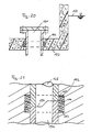
- FIG. 12 further, alternative mounting devices for the body 102 are shown.
- the screw 107 shown as well as pins or nails can be encompassed by a tubular spacer 110 in the shaft area, the length of which Cross-sectional height of the body 102 corresponds.
- a holder can also be made via a holder profile 109, which is U-shaped in cross section in the area of the body 102 and engages around the side surfaces 103 and the underside 104 of the body 102.
- a side leg of the support profile 109 is guided up to the concrete surface 101 and there bends approximately at right angles to form a web area which rests on the concrete surface 101. In this area, the mounting profile 109 can then be attached to the concrete surface 101, for example by means of a shot-in pin or nail.
- FIG. 12 also shows that the body 102 has a longitudinally extending, continuous recess in its cross-sectional interior, which serves as a free through channel 106a for the sealing medium.
- the sealing medium introduced into the body 102 will thus first fill the free through channel 106a of the body 102 and then exit through the porous material of the body 102 into the joint area.
- the cross-sectional interior of the body 102 can also have a plurality of continuous recesses running next to one another.
- FIGS. 11 and 12 show a preferred cross-sectional shape of the body 102 in the form of a cuboid and thus having a rectangular cross-section.
- the same advantageous properties of this sealing device can, however, also be achieved with bodies which have, for example, a trapezoidal or circular section-like cross section or also cross sections of any other design.
- a separate representation of alternative cross-sectional shapes of the sealing device was omitted. This possibility of alternatives Cross-sectional shapes of the sealing device also relate to the connecting elements subsequently described in FIGS. 13 to 17 and to the press-in connector body 123 shown in FIG. 18.
- connecting elements having the same cross-sectional shape and made of the same material are provided between their abutting edges, which are shown in FIGS. 13 to 17 and represent a non-exhaustive selection of preferred connecting elements.
- the task of these connection elements is not only the aforementioned connection of two bodies 102, but also the possibility of a change of direction with the aid of such connection elements.
- the bodies 102 are simply attached to the connecting elements so that their free connection ends lie flush against one another.
- 13 to 17 illustrate that straight connecting pieces 114 (FIG. 13), flat corner brackets 115 (FIG. 14), upright corner brackets 116 (FIG. 15), T-pieces 117 (FIG. 16) and crossing pieces 118 (FIG. 17) can be used, for example.
- the connecting elements are fastened in the manner already described by means of screws, pins, nails or mounting profiles, as are the bodies 102 on the concrete surface 1.
- connection of the bodies 102 to one another or the bodies 102 to the connecting elements at the respective joints is preferably carried out with the aid of an adhesive tape which is placed over the joint, the adhesive tape preferably covering only the top 104 and the side surfaces 103, the adhesive tape on the Side surfaces 103 can end at a distance from the concrete surface 101, so that the sealing medium can also emerge from the area of the joint in this area.
- the adhesive tape also serves primarily to prevent cement slurry and small particles from penetrating into the joint area during the concreting process.
- a Einpreßstutz stresses 123 is shown, on the an elastic, load-bearing, non-porous hose 121 is arranged in the area 124 on one side surface 102.
- This hose 121 serves as a filler neck for the sealing medium and is arranged outside the second concrete section or outside its formwork with its free end.
- the hose 121 preferably ends in the cross-sectional interior of the press-fit connector body 123 or in a free through channel 106a, if such should be provided.
- the sealing device will preferably have a further press-in connector 123 at another point, in particular in the end region of the sealing device, with which it can be checked whether the sealing medium has also penetrated the entire sealing device during the pressing in. In order to have several control points or press-in points for the sealing medium, a plurality of such press-in connector bodies 123 can also be provided.
- the body 102 can not only be laid on flat concrete surfaces, but also curved or circular surfaces, e.g. surrounded by pipes or tubes, cuff-like or follow curved concrete surfaces.
- curved or circular surfaces e.g. surrounded by pipes or tubes, cuff-like or follow curved concrete surfaces.
- V-shaped, notch-like incisions extending over their entire cross-sectional width are provided, as shown in FIG. 19a. These incisions represent notches 125, with their respective notch tip 126 ending somewhat below the cross-sectional height or the top 104 of the body 102.
- Such a body 102 having notches 125 can then, as shown in FIG. 19b, either follow an arcuate course or be bent into a ring (not shown) since the body 102 is sufficiently flexible.
- the body 102 is then placed, for example, against the lateral surface of a tube (not shown) and bent accordingly and then also fastened on the tube.
- the notch edge surfaces 127 touch or abut each other when the underside 105 abuts, for example, the pipe surface. This ensures that the then ring-shaped body 102 continues to be a continuous foam tape and has no imperfections into which the concrete of the second concreting section can penetrate and would thus prevent the sealing medium from penetrating.
- the body 102 without arranging notches 125 in order to adapt it to curved concrete surfaces 101 or to place it in a ring or cuff-like manner around circular bodies.
- the foam or the filter foam of the body 102 can be compressed for this bend without the passage pores required for the passage of the sealing medium being closed by the compression of the body 102.
- the sealing medium is fed or pressed into the body 102 via supply means, not shown, from which it can then penetrate into the cavities of the joint area to be filled in a sealing manner.
- a preferred attachment of the body 102 or the connecting elements or the press-fit connector body 123 is carried out on circular elements with an endless rubber band, in that the rubber band is stretched over the upper side, for example of the body 102 or other elements mentioned.
- the rubber band then ensures a tight hold of the ring-shaped sealing device on the corresponding circular element.
- the width of the rubber band can preferably be less than the cross-sectional width of the top 104 of the body 102, so that sufficient sealing medium can also escape into the joint area to be sealed in the area of the top 104.
- FIG. 20 shows a preferred use of the body 102 and / or its connecting elements or the press-in connector body 123 for sealing a groundwater relief connector 131.
- the body 102 is provided with notches 125 in the manner shown in FIGS. 19a and 19b.
- the body 102 surrounds the groundwater relief nozzle 131 in a ring-like manner the area in which the groundwater relief port 131 penetrates the bottom plate 132, which is made of concrete. This location in the base plate 132 is particularly at risk from penetrating groundwater or moisture, in particular if, as shown, the groundwater level 133 lies above the base plate 132.
- the body 102 Before concreting the floor slab 132 - with an artificially lowered groundwater table 133 - the body 102 is placed in a ring around the groundwater relief connection 131 and fastened there, for example, with the rubber band mentioned. After the base plate 132 has been concreted, the sealing medium is pressed into the body 102 via previously arranged filling devices or with the aid of the method according to claim 46. The joint area between the groundwater relief connection 131 and the base plate 132 is completely sealed after the sealing medium has emerged from the body 102 into the cavities present there.
- Another preferred use of the body arises when sealing a joint area between a body, for example a pipe and a concrete section, if liquids are constantly or occasionally present on one side of the concrete section, as is the case, for example, in water basins with concrete walls.
- Pipes or other devices that are present on the water side can be surrounded by the body 102 and, by subsequently injecting the sealing medium into the body 102, securely seal the joint area which is susceptible to the ingress of water.
- FIG. 21 A further preferred use of the body 102 and / or the connecting elements and the press-in connector 123 is shown in FIG. 21, the body 102 serving there to seal a connection point between two pipes 134, 135.
- the tubes 134, 135 are placed against one another via a Z-shaped connection point 136.
- This connection point 136 is a weak point in pipelines with regard to the escape of media carried in the pipelines.
- the body 102 is attached directly to the connection point 136 so that it encompasses this connection point 136 in a ring-like manner.
- the body 102 is designed prior to attachment to the connection point 136 as shown in FIGS. 19a and 19b, or - without being provided with notches 125 - simply bent correspondingly in a ring-like manner.
- the body 102 is preferably attached to the connection point 136 using the rubber band mentioned.
- the pipe connection point 136 shown is generally surrounded by a medium, for example mortar or soil or the like.
- the connection point is sealed, ie the sealing medium is introduced into the body 102, preferably after the entire pipe connection has been completed, so that the connection point 136 may already be surrounded by a specific medium.
- the sealing medium is introduced into the body 102 in the manner explained for FIG. 20. Since in this case a seal is only necessary at the connection point 136 of the two pipes 134, 135, the top 104 and the side surfaces 103 can be sealed with, for example, an adhesive tape, since it is evident that an escape of the sealing medium is only necessary in the direction of the two pipes 134, 135.
- the upper side 104 can preferably be sealed by the arrangement of the rubber band.
- the body 102 is also advantageously suitable for sealing a pipe socket connection point, wherein the body 102 is preferably arranged obliquely to the pipe socket or its cross section is adapted to the pipe socket connection point, for example has a triangular cross section.
- sealing device 138 is shown schematically in the joint area, which was applied to the concrete surface 101 before the concrete wall 137 was encased and concreted. Instead of previously arranged filler necks, which as a rule produce hose-like connections to the sealing device, in the method according to the invention the sealing device 138 is concreted in without such or a similarly designed connection.
- connection points or bores 139 are preferably provided, so that the sealing medium can be introduced at several points and control points are present at which it can be checked whether the sealing medium also penetrates the entire sealing device.
- Control or entry points in the form of bores 139 are preferably arranged at the start or end area of the joint, as seen in the longitudinal direction. It is up to the local conditions whether the connection is preferably led horizontally or obliquely to the sealing device 138.
Priority Applications (3)
| Application Number | Priority Date | Filing Date | Title |
|---|---|---|---|
| EP94107063A EP0629751A3 (fr) | 1989-09-08 | 1990-09-10 | Procédé pour introduire un produit d'étanchéisation dans un joint. |
| EP94107062A EP0629750B1 (fr) | 1989-09-08 | 1990-09-10 | Procédé pour l'étanchéification d'un joint par injection d'un milieu d'étanchéité |
| GR970401201T GR3023550T3 (en) | 1989-09-08 | 1997-05-23 | Sealing device for concrete joints, its use and realisation process. |
Applications Claiming Priority (2)
| Application Number | Priority Date | Filing Date | Title |
|---|---|---|---|
| DE8910744U DE8910744U1 (fr) | 1989-09-08 | 1989-09-08 | |
| DE8910744U | 1989-09-08 |
Related Child Applications (2)
| Application Number | Title | Priority Date | Filing Date |
|---|---|---|---|
| EP94107063.3 Division-Into | 1990-09-10 | ||
| EP94107062.5 Division-Into | 1990-09-10 |
Publications (2)
| Publication Number | Publication Date |
|---|---|
| EP0418699A1 true EP0418699A1 (fr) | 1991-03-27 |
| EP0418699B1 EP0418699B1 (fr) | 1995-02-22 |
Family
ID=6842678
Family Applications (3)
| Application Number | Title | Priority Date | Filing Date |
|---|---|---|---|
| EP94107063A Withdrawn EP0629751A3 (fr) | 1989-09-08 | 1990-09-10 | Procédé pour introduire un produit d'étanchéisation dans un joint. |
| EP90117399A Expired - Lifetime EP0418699B1 (fr) | 1989-09-08 | 1990-09-10 | Appareil d'étanchéité de joints de reprise de bétonnage et procédé pour remplir l'appareil |
| EP94107062A Expired - Lifetime EP0629750B1 (fr) | 1989-09-08 | 1990-09-10 | Procédé pour l'étanchéification d'un joint par injection d'un milieu d'étanchéité |
Family Applications Before (1)
| Application Number | Title | Priority Date | Filing Date |
|---|---|---|---|
| EP94107063A Withdrawn EP0629751A3 (fr) | 1989-09-08 | 1990-09-10 | Procédé pour introduire un produit d'étanchéisation dans un joint. |
Family Applications After (1)
| Application Number | Title | Priority Date | Filing Date |
|---|---|---|---|
| EP94107062A Expired - Lifetime EP0629750B1 (fr) | 1989-09-08 | 1990-09-10 | Procédé pour l'étanchéification d'un joint par injection d'un milieu d'étanchéité |
Country Status (7)
| Country | Link |
|---|---|
| US (3) | US5249401A (fr) |
| EP (3) | EP0629751A3 (fr) |
| AT (2) | ATE118854T1 (fr) |
| DE (4) | DE8910744U1 (fr) |
| DK (2) | DK0418699T3 (fr) |
| ES (2) | ES2068958T3 (fr) |
| GR (1) | GR3023550T3 (fr) |
Cited By (13)
| Publication number | Priority date | Publication date | Assignee | Title |
|---|---|---|---|---|
| WO1992020879A1 (fr) * | 1991-05-17 | 1992-11-26 | Rascor Spezialbau Gmbh | Procede et element d'etanchement d'un joint dans un element de construction |
| US5249401A (en) * | 1989-09-08 | 1993-10-05 | Schmid Rene P | Sealing device for concrete joints and process for the introducing of a sealing medium into sealing devices |
| WO1994002694A1 (fr) * | 1992-07-20 | 1994-02-03 | Rascor Spezialbau Gmbh | Dispositif et procede pour injecter un coulis d'injection dans des systemes de jointement de betonnage |
| WO1994018398A1 (fr) * | 1993-02-01 | 1994-08-18 | Bjarne Sem | Systeme d'injection permettant d'obturer des joints dans des structures en beton |
| EP0679772A1 (fr) * | 1993-11-12 | 1995-11-02 | Asahi Denka Kogyo Kabushiki Kaisha | Plaque decoupee se dilatant dans l'eau |
| DE4422648A1 (de) * | 1994-06-28 | 1996-01-11 | Rene P Schmid | Sollriß-Fugenschiene |
| WO1996022429A1 (fr) * | 1995-01-18 | 1996-07-25 | Agrar Chemie Ag. | Systeme d'etancheite pour rendre des joints de beton etanches |
| EP0725195A2 (fr) * | 1992-05-13 | 1996-08-07 | Rascor Spezialbau Gmbh | Méthode et dispositif pour la construction de murs en béton avec emploi de coffrages tendus |
| DE4244972C2 (de) * | 1992-10-22 | 2002-06-13 | Roland Wolf Gmbh | Vorrichtung zur Abdichtung von Trennfugen, insbesondere Betonier fugen |
| DE10107745A1 (de) * | 2001-02-16 | 2002-09-19 | Stekox Gmbh | Verpressschlauch zum Herstellen von wasserundurchlässigen oder nur gering wasserdurchlässigen, gasdichten und/oder kraftschlüssigen Bauwerksfugen |
| CN100357536C (zh) * | 2003-08-07 | 2007-12-26 | 农用化学公开股份有限公司 | 用于密封接缝的密封装置 |
| ITMI20120470A1 (it) * | 2012-03-26 | 2013-09-27 | Tecnochem Italiana S P A | Giunto per ripresa di getto, particolarmente per strutture in cemento armato a tenuta d'acqua. |
| WO2022043216A1 (fr) * | 2020-08-24 | 2022-03-03 | Hilti Aktiengesellschaft | Profilé d'étanchéité pour joint de bord, cloison sèche et procédé de fixation |
Families Citing this family (61)
| Publication number | Priority date | Publication date | Assignee | Title |
|---|---|---|---|---|
| GB9014990D0 (en) * | 1990-07-06 | 1990-08-29 | Nicolaidis Raphael | A constructional element and a process for its production |
| US5596860A (en) * | 1994-09-09 | 1997-01-28 | Insu-Form Incorporated | Foamed cement insulated metal frame building system |
| US5609006A (en) * | 1995-10-17 | 1997-03-11 | Boyer; Robert W. | Wall stud |
| US6412249B1 (en) | 1995-10-17 | 2002-07-02 | Boyer Building Products, Inc. | Wall stud |
| US5953871A (en) * | 1998-02-03 | 1999-09-21 | Design Board Industries Inc | Modular wall panel |
| US20030072905A1 (en) * | 2001-10-15 | 2003-04-17 | Ube Industries, Ltd. | Reinforced structure of metallic member |
| SE524524C2 (sv) * | 2001-11-26 | 2004-08-24 | Atlas Copco Tools Ab | Pneumatisk kraftverktyg med avloppsluftdeflektor |
| DE102004017008B4 (de) * | 2004-04-02 | 2009-10-22 | Aloys Wobben | Verfahren zum Errichten eines Turmes |
| DE102004017006B4 (de) * | 2004-04-02 | 2012-03-29 | Aloys Wobben | Verfahren zum Errichten eines Turmes |
| DE102004020530A1 (de) * | 2004-04-27 | 2005-11-24 | Roland Wolf | Bauwerkteil und Verfahren zur Herstellung eines solchen Bauwerkteils sowie Schalelement hierfür |
| CN101048557A (zh) * | 2004-08-03 | 2007-10-03 | 农用化学公开股份有限公司 | 用中空的异型挤出体密封两建筑体之间的接缝的密封装置 |
| US20100043335A1 (en) | 2005-06-22 | 2010-02-25 | O'connor Daniel | Stacking masonry block system with transition block and utility groove running therethrough |
| US7610730B2 (en) * | 2005-06-22 | 2009-11-03 | O'connor Daniel | Stacking masonry block system with locking starter device |
| US9637915B1 (en) | 2008-11-20 | 2017-05-02 | Emseal Joint Systems Ltd. | Factory fabricated precompressed water and/or fire resistant expansion joint system transition |
| US8365495B1 (en) | 2008-11-20 | 2013-02-05 | Emseal Joint Systems Ltd. | Fire and water resistant expansion joint system |
| US9670666B1 (en) | 2008-11-20 | 2017-06-06 | Emseal Joint Sytstems Ltd. | Fire and water resistant expansion joint system |
| US9739050B1 (en) | 2011-10-14 | 2017-08-22 | Emseal Joint Systems Ltd. | Flexible expansion joint seal system |
| US10851542B2 (en) | 2008-11-20 | 2020-12-01 | Emseal Joint Systems Ltd. | Fire and water resistant, integrated wall and roof expansion joint seal system |
| US9200437B1 (en) | 2008-12-11 | 2015-12-01 | Emseal Joint Systems Ltd. | Precompressed foam expansion joint system transition |
| US10316661B2 (en) | 2008-11-20 | 2019-06-11 | Emseal Joint Systems, Ltd. | Water and/or fire resistant tunnel expansion joint systems |
| US11180995B2 (en) | 2008-11-20 | 2021-11-23 | Emseal Joint Systems, Ltd. | Water and/or fire resistant tunnel expansion joint systems |
| US9631362B2 (en) | 2008-11-20 | 2017-04-25 | Emseal Joint Systems Ltd. | Precompressed water and/or fire resistant tunnel expansion joint systems, and transitions |
| US10066387B2 (en) | 2008-12-11 | 2018-09-04 | Emseal Joint Systems, Ltd. | Precompressed foam expansion joint system transition |
| US8341908B1 (en) | 2009-03-24 | 2013-01-01 | Emseal Joint Systems Ltd. | Fire and water resistant expansion and seismic joint system |
| US8813450B1 (en) | 2009-03-24 | 2014-08-26 | Emseal Joint Systems Ltd. | Fire and water resistant expansion and seismic joint system |
| US9068297B2 (en) | 2012-11-16 | 2015-06-30 | Emseal Joint Systems Ltd. | Expansion joint system |
| JP6156977B2 (ja) * | 2013-03-14 | 2017-07-05 | 住友ゴム工業株式会社 | 可撓性継手の固定構造 |
| US10480654B2 (en) | 2014-02-28 | 2019-11-19 | Schul International Co., Llc | Joint seal system having internal barrier and external wings |
| US9404581B1 (en) | 2014-02-28 | 2016-08-02 | Schul International Company, LLC | Joint seal system |
| US10087621B1 (en) | 2015-03-10 | 2018-10-02 | Schul International Company, LLC | Expansion joint seal system with isolated temperature-activated fire retarding members |
| US9206596B1 (en) | 2015-03-10 | 2015-12-08 | Schul International, Inc. | Expansion joint seal system |
| US10060122B2 (en) | 2015-03-10 | 2018-08-28 | Schul International Company, LLC | Expansion joint seal system |
| US9745738B2 (en) | 2015-12-30 | 2017-08-29 | Schul International Company, LLC | Expansion joint for longitudinal load transfer |
| US10066386B2 (en) | 2015-12-30 | 2018-09-04 | Schul International Company, LLC | Expansion joint seal with surface load transfer and intumescent |
| US9982428B2 (en) | 2015-12-30 | 2018-05-29 | Schul International Company, LLC | Expansion joint seal with surface load transfer, intumescent, and internal sensor |
| US10213962B2 (en) | 2015-12-30 | 2019-02-26 | Schul International Company, LLC | Expansion joint seal with load transfer and flexion |
| US10352039B2 (en) | 2016-03-07 | 2019-07-16 | Schul International Company, LLC | Durable joint seal system with cover plate and ribs |
| US10352003B2 (en) | 2016-03-07 | 2019-07-16 | Schul International Company, LLC | Expansion joint seal system with spring centering |
| US9765486B1 (en) | 2016-03-07 | 2017-09-19 | Schul International Company, LLC | Expansion joint seal for surface contact applications |
| US10240302B2 (en) | 2016-03-07 | 2019-03-26 | Schul International Company, LLC | Durable joint seal system with detachable cover plate and rotatable ribs |
| US9915038B2 (en) | 2016-03-07 | 2018-03-13 | Schul International Company, LLC | Durable joint seal system with detachable cover plate and rotatable ribs |
| US9803357B1 (en) | 2016-07-22 | 2017-10-31 | Schul International Company, LLC | Expansion joint seal system providing fire retardancy |
| US10280611B1 (en) | 2016-07-22 | 2019-05-07 | Schul International Company, LLC | Vapor permeable water and fire-resistant expansion joint seal |
| US10323407B1 (en) | 2016-07-22 | 2019-06-18 | Schul International Company, LLC | Water and fire-resistant expansion joint seal |
| US10323408B1 (en) | 2016-07-22 | 2019-06-18 | Schul International Company, LLC | Durable water and fire-resistant tunnel expansion joint seal |
| US10081939B1 (en) | 2016-07-22 | 2018-09-25 | Schul International Company, LLC | Fire retardant expansion joint seal system with internal resilient members and intumescent members |
| US10344471B1 (en) | 2016-07-22 | 2019-07-09 | Schull International Company, LLC | Durable water and fire-resistant expansion joint seal |
| US10087620B1 (en) | 2016-07-22 | 2018-10-02 | Schul International Company, LLC | Fire retardant expansion joint seal system with elastically-compressible body members, resilient members, and fire retardants |
| US10125490B2 (en) | 2016-07-22 | 2018-11-13 | Schul International Company, LLC | Expansion joint seal system with internal intumescent springs providing fire retardancy |
| US10358813B2 (en) | 2016-07-22 | 2019-07-23 | Schul International Company, LLC | Fire retardant expansion joint seal system with elastically-compressible body members, internal spring members, and connector |
| US10280610B1 (en) | 2016-07-22 | 2019-05-07 | Schul International Company, LLC | Vapor-permeable water and fire-resistant expansion joint seal |
| US10087619B1 (en) | 2016-07-22 | 2018-10-02 | Schul International Company, LLC | Fire retardant expansion joint seal system with elastically-compressible members and resilient members |
| US10227734B1 (en) | 2017-12-26 | 2019-03-12 | Veloxion, Inc. | Helically-packaged expansion joint seal system |
| US10385565B2 (en) * | 2017-12-26 | 2019-08-20 | Schul International Co., Llc | Helically packaged expansion joint seal system prepared for change in direction |
| US20190218796A1 (en) * | 2018-01-18 | 2019-07-18 | Edgeban, LLC | Edging Forms for Producing Self-Leveling Floors and Methods of Use |
| US10851541B2 (en) | 2018-03-05 | 2020-12-01 | Schul International Co., Llc | Expansion joint seal for surface contact with offset rail |
| US10323409B1 (en) | 2018-07-12 | 2019-06-18 | Schul International Company, LLC | Expansion joint system with flexible sheeting |
| NL2023031B1 (en) * | 2019-04-30 | 2020-11-23 | Trelleborg Ridderkerk B V | Waterstop joint and method of installing a waterstop joint |
| CN112854493B (zh) * | 2021-01-07 | 2022-05-17 | 刘闪闪 | 装配式混凝土建筑预制外墙拼缝排水管施工方法 |
| US11459746B1 (en) * | 2021-02-02 | 2022-10-04 | Schul International Co., Llc | Foam-based seal for angular expansion joint segments |
| FR3138922A1 (fr) * | 2022-08-22 | 2024-02-23 | Dagard | Dispositif de liaison pour panneaux plans de salle propre. |
Citations (10)
| Publication number | Priority date | Publication date | Assignee | Title |
|---|---|---|---|---|
| US2156681A (en) * | 1936-06-18 | 1939-05-02 | Goodrich Co B F | Sealing strip |
| CH338337A (fr) * | 1955-08-18 | 1959-05-15 | Grandvoinet Pierre | Gaine isolante hélicoïdale et procédé de fabrication de cette gaine |
| GB961664A (en) * | 1959-07-10 | 1964-06-24 | Servicised Products Corp | Waterstop connector |
| GB1289550A (fr) * | 1969-12-30 | 1972-09-20 | ||
| CH574023A5 (en) * | 1973-07-24 | 1976-03-31 | Schmitter Adolf | Junction seal for channels or conduits - has ring expansion member anchored to one channel inflated to force ends apart |
| FR2332373A1 (fr) * | 1975-11-20 | 1977-06-17 | Mat Inter Sa | Procede d'etancheification d'un joint de reprise de betonnage |
| CH600077A5 (en) * | 1976-04-06 | 1978-06-15 | Peter Kaufmann | Seal for gaps in concrete structures |
| FR2538077A1 (fr) * | 1982-12-17 | 1984-06-22 | Hutchinson Sa | Nouveaux materiaux d'isolation thermique et tuyauteries soumises a des contraintes thermiques, hydrostatiques et mecaniques et procedes d'isolation thermique de ces tuyauteries en utilisant lesdits materiaux |
| DE8525266U1 (de) * | 1985-09-04 | 1986-01-02 | Max Frank Gmbh & Co Kg, 8441 Leiblfing | Injektionsschlauch für Betonfugen |
| DE8708424U1 (fr) * | 1987-06-15 | 1987-08-06 | Tiletschke, Lothar, 4904 Enger, De |
Family Cites Families (27)
| Publication number | Priority date | Publication date | Assignee | Title |
|---|---|---|---|---|
| US1243001A (en) * | 1916-04-06 | 1917-10-16 | Gertrude F Stewart | Protected metal structure. |
| US1716994A (en) * | 1926-08-09 | 1929-06-11 | George M Wehrle | Method of joint sealing |
| US1691402A (en) * | 1926-09-29 | 1928-11-13 | Oden Eugene Robert | Means for sealing expansion joints |
| US2277286A (en) * | 1936-11-05 | 1942-03-24 | American Colloid Co | Method and means for impeding the seepage or flow of water |
| US2178388A (en) * | 1939-04-21 | 1939-10-31 | Beckman Lawrence | Binder canvas slat protector |
| FR985002A (fr) * | 1949-02-15 | 1951-07-13 | Pièces élémentaires de formes spéciales combinables entre elles pour obtenir desparois à dispositions multiples | |
| US2908157A (en) * | 1953-10-30 | 1959-10-13 | Foster Wheeler Corp | Composite firebrick |
| US3111069A (en) * | 1962-08-13 | 1963-11-19 | Allied Chem | Paving joint construction |
| US3381432A (en) * | 1966-09-19 | 1968-05-07 | Inventor S Group | Stressed-skin span structure |
| US3629986A (en) * | 1969-12-22 | 1971-12-28 | Mfg Associates Inc | Expansion joint filler |
| GB1300143A (en) * | 1970-01-29 | 1972-12-20 | Silent Channel Prod Ltd | Improvements in or relating to a method and means for the sealing of roof or other structures |
| USRE29377E (en) * | 1972-11-16 | 1977-08-30 | Frangible concrete-joint sealant package | |
| US3903587A (en) * | 1973-07-20 | 1975-09-09 | Boiardi Products Corp | Method of installing a divider strip in a terrazzo floor |
| US4346544A (en) * | 1978-10-11 | 1982-08-31 | Larssen Jens Frederik | Lightweight building elements with high carrying capacity |
| US4346542A (en) * | 1979-07-09 | 1982-08-31 | Kohkichi Tateno | Joint for use in concrete deposit |
| CH643623A5 (de) * | 1980-03-05 | 1984-06-15 | Aquarius Fuer Dichte Bauten Ag | Schlauchartige dichtungsvorrichtung fuer betonfugen. |
| JPS5789068A (en) * | 1980-11-20 | 1982-06-03 | Sho Bond Const | Injection of adhesive |
| US4486994A (en) * | 1981-03-09 | 1984-12-11 | Industrial Sheet Metal & Mechanical Corp. | Panel wall construction having airtight joint and method of forming same |
| US4486995A (en) * | 1982-04-05 | 1984-12-11 | Allen Robert L | Insulating panel |
| DE3315632C2 (de) * | 1983-04-29 | 1986-05-07 | Siegfried 7135 Wiernsheim Fricker | Ankerschiene für Bautechnik |
| DE8335231U1 (de) * | 1983-12-08 | 1984-03-08 | De Neef Chemie S.A. N.V., 3100 Heist o/d Berg | Betonfugen-Dichtungsvorrichtung |
| US4653956A (en) * | 1984-12-12 | 1987-03-31 | Lang Frederic A | Highway pavement |
| DE8608396U1 (de) * | 1986-03-27 | 1986-05-28 | Max Frank GmbH & Co KG, 8448 Leiblfing | Injektionsschlauch für Betonfugen |
| US4733513A (en) * | 1986-10-21 | 1988-03-29 | Schrader Ernest K | Tying bar for concrete joints |
| DE3936040A1 (de) * | 1989-09-07 | 1991-05-29 | Fischer Artur Werke Gmbh | Injektionspacker zum injizieren von kunstharz in betonrisse |
| DE8910744U1 (fr) * | 1989-09-08 | 1991-01-17 | Schmidt, Rene P., Oberweningen, Ch | |
| US5257486A (en) * | 1991-04-23 | 1993-11-02 | Adhesives Technology Corporation 1987 | Nozzle for injecting a sealant into a crack |
-
1989
- 1989-09-08 DE DE8910744U patent/DE8910744U1/de not_active Expired - Lifetime
-
1990
- 1990-09-05 US US07/578,830 patent/US5249401A/en not_active Expired - Lifetime
- 1990-09-10 DE DE59010719T patent/DE59010719D1/de not_active Expired - Lifetime
- 1990-09-10 EP EP94107063A patent/EP0629751A3/fr not_active Withdrawn
- 1990-09-10 ES ES90117399T patent/ES2068958T3/es not_active Expired - Lifetime
- 1990-09-10 EP EP90117399A patent/EP0418699B1/fr not_active Expired - Lifetime
- 1990-09-10 ES ES94107062T patent/ES2103518T3/es not_active Expired - Lifetime
- 1990-09-10 DK DK90117399.7T patent/DK0418699T3/da active
- 1990-09-10 DE DE59008512T patent/DE59008512D1/de not_active Expired - Lifetime
- 1990-09-10 DK DK94107062.5T patent/DK0629750T3/da active
- 1990-09-10 AT AT90117399T patent/ATE118854T1/de not_active IP Right Cessation
- 1990-09-10 EP EP94107062A patent/EP0629750B1/fr not_active Expired - Lifetime
- 1990-09-10 DE DE9017874U patent/DE9017874U1/de not_active Expired - Lifetime
- 1990-09-10 AT AT94107062T patent/ATE153411T1/de not_active IP Right Cessation
-
1993
- 1993-07-06 US US08/086,093 patent/US5377469A/en not_active Expired - Fee Related
- 1993-07-06 US US08/085,837 patent/US5327693A/en not_active Expired - Lifetime
-
1997
- 1997-05-23 GR GR970401201T patent/GR3023550T3/el unknown
Patent Citations (10)
| Publication number | Priority date | Publication date | Assignee | Title |
|---|---|---|---|---|
| US2156681A (en) * | 1936-06-18 | 1939-05-02 | Goodrich Co B F | Sealing strip |
| CH338337A (fr) * | 1955-08-18 | 1959-05-15 | Grandvoinet Pierre | Gaine isolante hélicoïdale et procédé de fabrication de cette gaine |
| GB961664A (en) * | 1959-07-10 | 1964-06-24 | Servicised Products Corp | Waterstop connector |
| GB1289550A (fr) * | 1969-12-30 | 1972-09-20 | ||
| CH574023A5 (en) * | 1973-07-24 | 1976-03-31 | Schmitter Adolf | Junction seal for channels or conduits - has ring expansion member anchored to one channel inflated to force ends apart |
| FR2332373A1 (fr) * | 1975-11-20 | 1977-06-17 | Mat Inter Sa | Procede d'etancheification d'un joint de reprise de betonnage |
| CH600077A5 (en) * | 1976-04-06 | 1978-06-15 | Peter Kaufmann | Seal for gaps in concrete structures |
| FR2538077A1 (fr) * | 1982-12-17 | 1984-06-22 | Hutchinson Sa | Nouveaux materiaux d'isolation thermique et tuyauteries soumises a des contraintes thermiques, hydrostatiques et mecaniques et procedes d'isolation thermique de ces tuyauteries en utilisant lesdits materiaux |
| DE8525266U1 (de) * | 1985-09-04 | 1986-01-02 | Max Frank Gmbh & Co Kg, 8441 Leiblfing | Injektionsschlauch für Betonfugen |
| DE8708424U1 (fr) * | 1987-06-15 | 1987-08-06 | Tiletschke, Lothar, 4904 Enger, De |
Cited By (25)
| Publication number | Priority date | Publication date | Assignee | Title |
|---|---|---|---|---|
| US5249401A (en) * | 1989-09-08 | 1993-10-05 | Schmid Rene P | Sealing device for concrete joints and process for the introducing of a sealing medium into sealing devices |
| WO1992020879A1 (fr) * | 1991-05-17 | 1992-11-26 | Rascor Spezialbau Gmbh | Procede et element d'etanchement d'un joint dans un element de construction |
| EP0725195A2 (fr) * | 1992-05-13 | 1996-08-07 | Rascor Spezialbau Gmbh | Méthode et dispositif pour la construction de murs en béton avec emploi de coffrages tendus |
| MD1885C2 (ro) * | 1992-05-13 | 2002-10-31 | Раскор Спезиалбау Гмбх | Procedeu de ridicare a peretelui de beton utilizând cofrajul, distanţier tubular pentru fixarea panourilor cofrajului la ridicarea peretelui de beton şi dispozitiv pentru realizarea acestui procedeu |
| US6159399A (en) * | 1992-05-13 | 2000-12-12 | Rascor Spezialbau Gmbh | Procedure for the erection of concrete walls using braced boardings and device to carry out the same |
| EP0725195A3 (fr) * | 1992-05-13 | 1996-11-13 | Rascor Spezialbau Gmbh | Méthode et dispositif pour la construction de murs en béton avec emploi de coffrages tendus |
| WO1994002694A1 (fr) * | 1992-07-20 | 1994-02-03 | Rascor Spezialbau Gmbh | Dispositif et procede pour injecter un coulis d'injection dans des systemes de jointement de betonnage |
| US5643402A (en) * | 1992-07-20 | 1997-07-01 | Rascor Spezialbau Gmbh | Method and device for pressing injection material into the joints between concrete bodies |
| DE4244972C2 (de) * | 1992-10-22 | 2002-06-13 | Roland Wolf Gmbh | Vorrichtung zur Abdichtung von Trennfugen, insbesondere Betonier fugen |
| DE4244972C5 (de) * | 1992-10-22 | 2006-04-13 | Roland Wolf Gmbh | Vorrichtung zur Abdichtung von Trennfugen, insbesondere Betonier fugen |
| WO1994018398A1 (fr) * | 1993-02-01 | 1994-08-18 | Bjarne Sem | Systeme d'injection permettant d'obturer des joints dans des structures en beton |
| EP0679772A1 (fr) * | 1993-11-12 | 1995-11-02 | Asahi Denka Kogyo Kabushiki Kaisha | Plaque decoupee se dilatant dans l'eau |
| EP0679772A4 (fr) * | 1993-11-12 | 1996-03-27 | Asahi Denka Kogyo Kk | Plaque decoupee se dilatant dans l'eau. |
| LT4229B (en) | 1994-06-28 | 1997-10-27 | Rascor Spezialbau Gmbh | Contraction joint rail |
| DE4422648C2 (de) * | 1994-06-28 | 1998-09-03 | Rene P Schmid | Sollriß-Fugenschiene |
| DE4422648A1 (de) * | 1994-06-28 | 1996-01-11 | Rene P Schmid | Sollriß-Fugenschiene |
| WO1996000822A1 (fr) * | 1994-06-28 | 1996-01-11 | Rascor Spezialbau Gmbh | Rail de joint de retrait |
| EP0922814A3 (fr) * | 1995-01-18 | 1999-06-30 | Agrar Chemie AG | Système d'étanchéité pour rendre les joints de béton étanches |
| DE19501384C2 (de) * | 1995-01-18 | 2001-10-04 | Rene P Schmid | Dichtungsvorrichtung zum Abdichten von Betonierfugen |
| WO1996022429A1 (fr) * | 1995-01-18 | 1996-07-25 | Agrar Chemie Ag. | Systeme d'etancheite pour rendre des joints de beton etanches |
| DE19501384A1 (de) * | 1995-01-18 | 1996-08-08 | Rene P Schmid | Dichtungsvorrichtung zum Abdichten von Betonfugen |
| DE10107745A1 (de) * | 2001-02-16 | 2002-09-19 | Stekox Gmbh | Verpressschlauch zum Herstellen von wasserundurchlässigen oder nur gering wasserdurchlässigen, gasdichten und/oder kraftschlüssigen Bauwerksfugen |
| CN100357536C (zh) * | 2003-08-07 | 2007-12-26 | 农用化学公开股份有限公司 | 用于密封接缝的密封装置 |
| ITMI20120470A1 (it) * | 2012-03-26 | 2013-09-27 | Tecnochem Italiana S P A | Giunto per ripresa di getto, particolarmente per strutture in cemento armato a tenuta d'acqua. |
| WO2022043216A1 (fr) * | 2020-08-24 | 2022-03-03 | Hilti Aktiengesellschaft | Profilé d'étanchéité pour joint de bord, cloison sèche et procédé de fixation |
Also Published As
| Publication number | Publication date |
|---|---|
| DE9017874U1 (fr) | 1992-09-10 |
| GR3023550T3 (en) | 1997-08-29 |
| DE8910744U1 (fr) | 1991-01-17 |
| EP0418699B1 (fr) | 1995-02-22 |
| ES2103518T3 (es) | 1997-09-16 |
| EP0629750A2 (fr) | 1994-12-21 |
| DK0629750T3 (da) | 1997-08-25 |
| US5249401A (en) | 1993-10-05 |
| ATE118854T1 (de) | 1995-03-15 |
| DE59008512D1 (de) | 1995-03-30 |
| DE59010719D1 (de) | 1997-06-26 |
| EP0629750A3 (en) | 1995-01-18 |
| ES2068958T3 (es) | 1995-05-01 |
| EP0629751A2 (fr) | 1994-12-21 |
| ATE153411T1 (de) | 1997-06-15 |
| US5377469A (en) | 1995-01-03 |
| EP0629750B1 (fr) | 1997-05-21 |
| US5327693A (en) | 1994-07-12 |
| EP0629751A3 (fr) | 1995-02-15 |
| DK0418699T3 (da) | 1995-03-27 |
Similar Documents
| Publication | Publication Date | Title |
|---|---|---|
| EP0418699B1 (fr) | Appareil d'étanchéité de joints de reprise de bétonnage et procédé pour remplir l'appareil | |
| EP0642620B1 (fr) | Procede pour edifier des murs en beton avec des coffrages precontraints, ecarteur tubulaire et dispositif permettant la mise en oeuvre dudit procede | |
| EP0804656B1 (fr) | Systeme d'etancheite pour rendre des joints de beton etanches | |
| DE19501384C9 (de) | Dichtungsvorrichtung zum Abdichten von Betonierfugen | |
| DE19722449A1 (de) | Abschalelement | |
| DE102005005525A1 (de) | Fugendichtungselement und Halter für Fugendichtungselemente | |
| DE4422648C2 (de) | Sollriß-Fugenschiene | |
| EP3452668B1 (fr) | Dispositif de stabilisation ultérieure de fissures de cavité de joint perméables à l'eau dans des ponts, tunnels et bâtiments | |
| DE1277541B (de) | Verfahren und Vorrichtung zum Anbringen von Verkleidungsplatten an einer Rohbauwand | |
| DE102018004529A1 (de) | Ankerschiene | |
| EP0952252B1 (fr) | Coffrage pour l'encastrement d'un rail | |
| CH687471A5 (de) | Verfahren zum Setzen eines Anschlag- oder Distanzhalters. | |
| DE19618138A1 (de) | Raumhohe Absperrvorrichtung | |
| DE8608396U1 (de) | Injektionsschlauch für Betonfugen | |
| DE19755603C2 (de) | Verpreßsystem zum Abdichten einer Arbeitsfuge zwischen zwei Baukörpern | |
| DE202007000445U1 (de) | Schalung zum Erzeugen einer Sollrissstelle | |
| EP2096223B1 (fr) | Dispositif de positionnement et d'ancrage à position et angle précis d'une barre de tension | |
| EP1229177A2 (fr) | Procédé d'étanchéification d'un joint de bétonnage et joint d'étanchéité correspondant | |
| DE19803438A1 (de) | Verankerungsvorrichtung und Anordnung zum Abschalen der Stirnseite einer Decke | |
| DE102004026429B3 (de) | Fugenbandhalterung sowie Herstellungsverfahren für Betonierungsabschnitte | |
| DE202004017823U1 (de) | Vorrichtung zum Abdichten von Betonfugen | |
| AT403716B (de) | Schalung für die herstellung einer leistenförmigen betonnase | |
| DE2309723C3 (de) | Verfahren und Vorrichtung zur Justierung von Fertigteilwänden und -stützen von Gebäuden | |
| EP1347122B1 (fr) | Dispositif d'injection sous pression et méthode d'insertion de ce dispositif dans un élément de construction | |
| AT525787A1 (de) | Abschalung hbv decke |
Legal Events
| Date | Code | Title | Description |
|---|---|---|---|
| PUAI | Public reference made under article 153(3) epc to a published international application that has entered the european phase |
Free format text: ORIGINAL CODE: 0009012 |
|
| AK | Designated contracting states |
Kind code of ref document: A1 Designated state(s): AT BE CH DE DK ES FR GB GR IT LI LU NL SE |
|
| 17P | Request for examination filed |
Effective date: 19910517 |
|
| 17Q | First examination report despatched |
Effective date: 19920518 |
|
| GRAA | (expected) grant |
Free format text: ORIGINAL CODE: 0009210 |
|
| AK | Designated contracting states |
Kind code of ref document: B1 Designated state(s): AT BE CH DE DK ES FR GB GR IT LI LU NL SE |
|
| REF | Corresponds to: |
Ref document number: 118854 Country of ref document: AT Date of ref document: 19950315 Kind code of ref document: T |
|
| XX | Miscellaneous (additional remarks) |
Free format text: TEILANMELDUNGEN 94107062.5, 94107063.3. |
|
| ET | Fr: translation filed | ||
| REG | Reference to a national code |
Ref country code: DK Ref legal event code: T3 |
|
| GBT | Gb: translation of ep patent filed (gb section 77(6)(a)/1977) |
Effective date: 19950224 |
|
| REF | Corresponds to: |
Ref document number: 59008512 Country of ref document: DE Date of ref document: 19950330 |
|
| ITF | It: translation for a ep patent filed |
Owner name: BUGNION S.P.A. |
|
| REG | Reference to a national code |
Ref country code: ES Ref legal event code: FG2A Ref document number: 2068958 Country of ref document: ES Kind code of ref document: T3 |
|
| REG | Reference to a national code |
Ref country code: GR Ref legal event code: FG4A Free format text: 3015992 |
|
| PLBE | No opposition filed within time limit |
Free format text: ORIGINAL CODE: 0009261 |
|
| STAA | Information on the status of an ep patent application or granted ep patent |
Free format text: STATUS: NO OPPOSITION FILED WITHIN TIME LIMIT |
|
| 26N | No opposition filed | ||
| REG | Reference to a national code |
Ref country code: GB Ref legal event code: IF02 |
|
| PGFP | Annual fee paid to national office [announced via postgrant information from national office to epo] |
Ref country code: GR Payment date: 20060811 Year of fee payment: 17 |
|
| PGFP | Annual fee paid to national office [announced via postgrant information from national office to epo] |
Ref country code: DK Payment date: 20060906 Year of fee payment: 17 |
|
| PGFP | Annual fee paid to national office [announced via postgrant information from national office to epo] |
Ref country code: ES Payment date: 20060915 Year of fee payment: 17 |
|
| PGFP | Annual fee paid to national office [announced via postgrant information from national office to epo] |
Ref country code: LU Payment date: 20060921 Year of fee payment: 17 |
|
| PGFP | Annual fee paid to national office [announced via postgrant information from national office to epo] |
Ref country code: NL Payment date: 20060930 Year of fee payment: 17 |
|
| PGFP | Annual fee paid to national office [announced via postgrant information from national office to epo] |
Ref country code: BE Payment date: 20061012 Year of fee payment: 17 |
|
| PGFP | Annual fee paid to national office [announced via postgrant information from national office to epo] |
Ref country code: SE Payment date: 20060907 Year of fee payment: 17 |
|
| BERE | Be: lapsed |
Owner name: *SCHMID RENE P. Effective date: 20070930 |
|
| PG25 | Lapsed in a contracting state [announced via postgrant information from national office to epo] |
Ref country code: SE Free format text: LAPSE BECAUSE OF NON-PAYMENT OF DUE FEES Effective date: 20070911 |
|
| REG | Reference to a national code |
Ref country code: DK Ref legal event code: EBP |
|
| EUG | Se: european patent has lapsed | ||
| PG25 | Lapsed in a contracting state [announced via postgrant information from national office to epo] |
Ref country code: NL Free format text: LAPSE BECAUSE OF NON-PAYMENT OF DUE FEES Effective date: 20080401 |
|
| NLV4 | Nl: lapsed or anulled due to non-payment of the annual fee |
Effective date: 20080401 |
|
| PG25 | Lapsed in a contracting state [announced via postgrant information from national office to epo] |
Ref country code: BE Free format text: LAPSE BECAUSE OF NON-PAYMENT OF DUE FEES Effective date: 20070930 |
|
| PG25 | Lapsed in a contracting state [announced via postgrant information from national office to epo] |
Ref country code: DK Free format text: LAPSE BECAUSE OF NON-PAYMENT OF DUE FEES Effective date: 20071001 |
|
| REG | Reference to a national code |
Ref country code: ES Ref legal event code: FD2A Effective date: 20070911 |
|
| PG25 | Lapsed in a contracting state [announced via postgrant information from national office to epo] |
Ref country code: ES Free format text: LAPSE BECAUSE OF NON-PAYMENT OF DUE FEES Effective date: 20070911 |
|
| PG25 | Lapsed in a contracting state [announced via postgrant information from national office to epo] |
Ref country code: GR Free format text: LAPSE BECAUSE OF NON-PAYMENT OF DUE FEES Effective date: 20080402 |
|
| PG25 | Lapsed in a contracting state [announced via postgrant information from national office to epo] |
Ref country code: LU Free format text: LAPSE BECAUSE OF NON-PAYMENT OF DUE FEES Effective date: 20070910 |
|
| PGFP | Annual fee paid to national office [announced via postgrant information from national office to epo] |
Ref country code: AT Payment date: 20090915 Year of fee payment: 20 Ref country code: GB Payment date: 20090916 Year of fee payment: 20 |
|
| PGFP | Annual fee paid to national office [announced via postgrant information from national office to epo] |
Ref country code: CH Payment date: 20091120 Year of fee payment: 20 Ref country code: DE Payment date: 20091124 Year of fee payment: 20 |
|
| PGFP | Annual fee paid to national office [announced via postgrant information from national office to epo] |
Ref country code: IT Payment date: 20090926 Year of fee payment: 20 |
|
| REG | Reference to a national code |
Ref country code: CH Ref legal event code: PL |
|
| REG | Reference to a national code |
Ref country code: GB Ref legal event code: PE20 Expiry date: 20100909 |
|
| PG25 | Lapsed in a contracting state [announced via postgrant information from national office to epo] |
Ref country code: GB Free format text: LAPSE BECAUSE OF EXPIRATION OF PROTECTION Effective date: 20100909 |
|
| PGFP | Annual fee paid to national office [announced via postgrant information from national office to epo] |
Ref country code: FR Payment date: 20091001 Year of fee payment: 20 |
|
| PG25 | Lapsed in a contracting state [announced via postgrant information from national office to epo] |
Ref country code: DE Free format text: LAPSE BECAUSE OF EXPIRATION OF PROTECTION Effective date: 20100910 |