EP0418699A1 - Sealing apparatus for concrete joints and procedure for its filling - Google Patents
Sealing apparatus for concrete joints and procedure for its filling Download PDFInfo
- Publication number
- EP0418699A1 EP0418699A1 EP90117399A EP90117399A EP0418699A1 EP 0418699 A1 EP0418699 A1 EP 0418699A1 EP 90117399 A EP90117399 A EP 90117399A EP 90117399 A EP90117399 A EP 90117399A EP 0418699 A1 EP0418699 A1 EP 0418699A1
- Authority
- EP
- European Patent Office
- Prior art keywords
- sealing device
- sealing
- profile
- concrete surface
- concrete
- Prior art date
- Legal status (The legal status is an assumption and is not a legal conclusion. Google has not performed a legal analysis and makes no representation as to the accuracy of the status listed.)
- Granted
Links
Images


Classifications
-
- E—FIXED CONSTRUCTIONS
- E04—BUILDING
- E04B—GENERAL BUILDING CONSTRUCTIONS; WALLS, e.g. PARTITIONS; ROOFS; FLOORS; CEILINGS; INSULATION OR OTHER PROTECTION OF BUILDINGS
- E04B1/00—Constructions in general; Structures which are not restricted either to walls, e.g. partitions, or floors or ceilings or roofs
- E04B1/62—Insulation or other protection; Elements or use of specified material therefor
- E04B1/66—Sealings
- E04B1/68—Sealings of joints, e.g. expansion joints
-
- E—FIXED CONSTRUCTIONS
- E02—HYDRAULIC ENGINEERING; FOUNDATIONS; SOIL SHIFTING
- E02D—FOUNDATIONS; EXCAVATIONS; EMBANKMENTS; UNDERGROUND OR UNDERWATER STRUCTURES
- E02D29/00—Independent underground or underwater structures; Retaining walls
- E02D29/16—Arrangement or construction of joints in foundation structures
-
- E—FIXED CONSTRUCTIONS
- E04—BUILDING
- E04B—GENERAL BUILDING CONSTRUCTIONS; WALLS, e.g. PARTITIONS; ROOFS; FLOORS; CEILINGS; INSULATION OR OTHER PROTECTION OF BUILDINGS
- E04B1/00—Constructions in general; Structures which are not restricted either to walls, e.g. partitions, or floors or ceilings or roofs
- E04B1/62—Insulation or other protection; Elements or use of specified material therefor
- E04B1/66—Sealings
- E04B1/68—Sealings of joints, e.g. expansion joints
- E04B1/6812—Compressable seals of solid form
-
- E—FIXED CONSTRUCTIONS
- E04—BUILDING
- E04B—GENERAL BUILDING CONSTRUCTIONS; WALLS, e.g. PARTITIONS; ROOFS; FLOORS; CEILINGS; INSULATION OR OTHER PROTECTION OF BUILDINGS
- E04B1/00—Constructions in general; Structures which are not restricted either to walls, e.g. partitions, or floors or ceilings or roofs
- E04B1/62—Insulation or other protection; Elements or use of specified material therefor
- E04B1/66—Sealings
- E04B1/68—Sealings of joints, e.g. expansion joints
- E04B1/6813—Compressable seals of hollow form
-
- E—FIXED CONSTRUCTIONS
- E04—BUILDING
- E04B—GENERAL BUILDING CONSTRUCTIONS; WALLS, e.g. PARTITIONS; ROOFS; FLOORS; CEILINGS; INSULATION OR OTHER PROTECTION OF BUILDINGS
- E04B1/00—Constructions in general; Structures which are not restricted either to walls, e.g. partitions, or floors or ceilings or roofs
- E04B1/62—Insulation or other protection; Elements or use of specified material therefor
- E04B1/66—Sealings
- E04B1/68—Sealings of joints, e.g. expansion joints
- E04B1/6816—Porous tubular seals for injecting sealing material
Definitions
- the invention relates to a sealing device for concrete joints according to the preambles of claims 1 and 33 and a method for introducing a sealing medium into sealing devices, as described in claim 49.
- a sealing device in the form of a porous tube is known from CH-PS 600 077.
- This hose consists of a support body in the form of a helical spring, which is surrounded by a first, braided hose, which in turn is surrounded by an outer, mesh-like, porous hose.
- the sealing device according to DE-GM 83 35 231 tries to remedy the disadvantage of the hose body becoming blocked by introducing a non-woven material between the support body in the form of a helical spring and the outer network-like hose, which material is permeable to liquid but impermeable to fine concrete particles .
- sealing medium is pressed directly into the beginning or end of the hose.
- the start and end of the hose must be freely accessible from the outside after completion of the concreting measures in the joint area.
- sealing medium can be introduced into sealing devices, in particular of the proposed type, in a simple, safe and inexpensive manner.
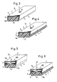
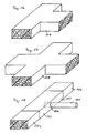
- the proposed sealing device is completely detached from the previous use of hose-like sealing devices and suggests the use of a profile which is open in cross-section and is hood-shaped.
- the profile is mounted with the free longitudinal edges of its side areas or side walls seated on the concrete surface, so that the free passage or flow channel is formed between the profile and the concrete surface, the sealing medium between the free longitudinal edges of the profile and the concrete surface in the joint area can leak.
- profiles can be produced quickly and inexpensively by injection or extrusion and can be laid in a simple manner will.
- silicates or hardening one- or multi-component plastics in liquid consistency are used as the sealing medium.
- Synthetic resin in particular 2-component acrylic resin, is also used as a sealing medium, as are bentonite and / or cement mixtures.
- the profile seen in cross section, is a U-shaped profile with a top wall and two side walls extending vertically therefrom.
- the stackability of the profiles during storage can be improved in that the profiles have a trapezoidal or arched cross section.
- An advantageous fastening of the profile is carried out by one or more screws, pins or nails, which encompass the transverse axis of the profile and encase it in the concrete.
- the fastening of the profiles can preferably be increased in that the screw or the nail is supported by their heads, preferably via a washer, on the ceiling area or the ceiling wall of the profile, with the shaft reaching through a hole in the ceiling wall and into the concrete surface , if necessary, enclose in a dowel inserted therein.
- a quick assembly of the profile is advantageously possible by shooting in the pin or the nail.
- Supporting the ceiling wall is made possible by clamping the ceiling wall between the head and the shaft.
- the clamping is preferably carried out via a lock nut on the screw, pin or nail.
- Another advantageous way of supporting the ceiling wall is via a spacer, which is between the concrete surface che and the inner surface of the ceiling wall is arranged.
- the production of the profiles is also particularly favorable because the entire profile consists of one and the same material.
- sealing lips preferably in one piece, can also be formed on the longitudinal edges, which also facilitate the escape of the sealing medium.
- the sealing lips are preferably elastic, in particular made of soft plastic or rubber or the like, which also facilitates the escape of the sealing medium.
- the profiles can also be attached to the concrete surface in the area of the web surface using suitable holding means.
- the interior of the profile is filled with an open through-pored plastic foam (filter foam), the sealing medium in the flow channel being conductive through the through-pores of the plastic foam.
- the plastic foam also supports the cross-sectional shape of the profile and ensures that the consumption of the sealing medium used is significantly reduced.
- the plastic foam is chosen so that it has enough large and large passage pores to prevent the sealing medium from entering not to hinder and even prevent.
- the interior of the profile can also be foamed with plastic foam or a plastic foam strip can be fitted into the interior.
- the interior can be filled quickly and inexpensively with the plastic foam.
- the plastic foam or the plastic foam strip advantageously has a protrusion beyond the longitudinal edges of the profiles. This protrusion ensures an enlarged cross section of the sealant from the profile.
- a free passage channel is provided in the longitudinal direction of the profile below the ceiling wall with a bottom wall arranged approximately in the middle of the height of the side walls, which has a longitudinal slot or similar passages, the flow channel being filled with plastic foam below the bottom wall.
- This configuration of the profile forms a free flow channel in which the sealing medium can initially enter and distribute unhindered, and then exit through the longitudinal cut into the plastic foam and from there into the joint area.
- the passage channel can preferably also be formed in that a groove running in the longitudinal direction of the profile is arranged in the inner surface of the profile facing the flow channel, preferably in the inner surface of the ceiling wall.
- connecting elements having the same cross-sectional shape of the profiles, preferably also made of plastic, are provided. With the help of such connecting elements, the profiles can be placed in any direction on the concrete surface che be arranged.
- the connecting elements are preferably straight connecting pieces, flat corner angles, upright corner angles, T-pieces or crossing pieces. With the help of the proposed connecting elements, the most important changes in direction can be made when laying the profiles.
- the connecting elements can be slipped onto the profiles and are preferably held thereon in a positive and non-positive manner.
- the connection of the individual profiles via the connecting elements is thus carried out in a simple manner and the proposed connection ensures that no sealing medium can emerge from the profiles in the joint area.
- the connecting elements can advantageously be screwed onto the concrete surface together with the profiles. Thus, only a bracket for profile and connecting element must be used at the joint.
- an impermeable adhesive tape is provided at the joints to prevent cement slurries and other particles from entering the profiles in the joint area during the concreting process and on the other hand the sealing medium escaping from the ceiling and side wall area. since it is actually not needed there.
- the adhesive tape is applied in the ceiling and side wall area of the joint and can also end before the free longitudinal edges are closed, since increased emergence in the lower area of the side walls may well be desirable.
- the butt joints can preferably also be welded.
- the profile or the connecting elements for injecting the sealing medium have a connection, in particular in the form of a tube or a non-porous hose, which with its free end is arranged outside the joint area or a formwork. Accordingly, certain elements of the sealing device can already be provided with such a connection, so that such a connection point no longer has to be created on site.
- the method for introducing the sealing medium described later can be used with particular advantage.
- the profiles or connecting elements in the side walls have notches with their corners or notch tips on the ceiling wall or just before the ceiling wall end up.
- the profiles or connecting elements are bent around their longitudinal axis and fastened on a curved concrete surface or on an arched or circular body, for example a pipe, the side edges of the notches abutting one another and the notches thus being closed, if the longitudinal edges of the side walls lie on the concrete surface or the body.
- the sealing device can be arranged not only on curved concrete surfaces, but even on curved or circular bodies. It is important that the notches are completely closed when the longitudinal edges lie against the concrete surface or the surface of the corresponding body.
- the notches can also be sealed with an adhesive tape.
- An advantageous way of fastening the profile is that the profile and / or a connecting elements are held by a tubular clamp-shaped bracket.
- the attachment for example to a reinforcement bar, is preferably carried out by the bracket at the free end of itself approximately parallel or slightly inclined to the concrete surface extending arm has a plug-in device for plugging, for example on a reinforcing bar.
- the plug-in device is formed by a bending of the holding arm by approximately 360 ° with an oblique course, preferably to the side of the support arm formed in this way, the side facing away from the profile to be held, the bending diameter and the distance of the starting area from the end area of the bend being greater than the diameter of the reinforcing bar.
- the proposed holding device can thus be arranged safely and immovably in a simple manner.
- the spring clip is preferably made of elastically bendable material, in particular spring steel, in order to be able to compensate for any tolerances.
- the bracket is bent from round wire, which can be easily and easily brought into the desired shape.
- the sealing device consists of a preferably cross-sectionally rectangular body made of a passage pores foam (filter foam) or a foam tape, which is placed on the concrete surface and mounted there, so that the passage or flow channel through the body itself is formed and that Sealing medium emerges from the passage pores into the joint area.
- a passage pores foam filter foam
- a foam tape which is placed on the concrete surface and mounted there, so that the passage or flow channel through the body itself is formed and that Sealing medium emerges from the passage pores into the joint area.
- the body can also have other shapes, for example a trapezoidal shape or a curved or a circular segment shape.
- the fact that the sealing medium A high degree of sealing in the area of the concrete joint is achieved not only in the area of the contact area of the foam tape in the joint area, but also from its side and ceiling area.
- a hose-like hollow body can be provided as the inlet opening for the sealing medium, for example, which is inserted into the body at one end and is arranged at the other end outside the second concreting section or its formwork.
- the method for introducing the sealing medium described later can be used with particular advantage.
- the foam or the foam tape used on the one hand has sufficient porosity for the passage of the sealing medium and on the other hand is of a consistency that largely avoids compression of the foam or the foam tape by the applied concrete.
- silicates or hardening single- or multi-component plastic in liquid consistency are used as sealing medium.
- Synthetic resin, in particular 2-component acrylic resin, is also used as a sealing medium, as are bentonite and / or cement mixtures.
- the body is advantageously fastened to the concrete surface by means of one or more pins, screws or nails which extend transversely to its longitudinal axis and surround the concrete and preferably have washers.
- the introduction of dowels in the concrete surface or by a predetermined setting of shooting devices ensures that the above-mentioned holding means only engage in the concrete surface to such an extent that their head region lies approximately in a plane with the surface of the body after the introduction.
- the desired end position of the pins, screws or nails can be achieved by using tubular spacers which encompass the holding means, the length of the spacers being approximately the cross-sectional height of the body corresponds. The spacer then ensures that the holding means do not penetrate too deep into the body.
- Another preferred mounting of the body can also be carried out by mounting profiles comprising it, which are mounted on the concrete surface.
- the support profiles can be metal or plastic straps that completely or partially encompass the cross-sectional circumference of the body, the support profiles being arranged with a free end on the concrete surface, so that the support device holds or clamps the body on the concrete surface without significantly reducing the cross section of the body at the bus stop.
- a continuous recess running in the longitudinal direction can be provided in the cross-sectional interior of the body and serves as a through-channel for the sealing medium.
- the through-channel is first filled and then the sealing medium penetrates the body until it emerges into the concrete area, closing off the existing joints.
- connection of at least two bodies on the abutting edges of the same is advantageously carried out by the same cross-sectional shape and made of the same material connecting elements.
- These connecting elements can be straight connecting pieces, flat corner brackets, upright corner brackets, T-pieces or crossing pieces, so that changes in direction can be easily taken into account when laying the body.
- An adhesive tape is preferably provided to connect the bodies to one another or the body to the connecting elements at the joints.
- the tape is used primarily for Securing the position of the body and can preferably be attached only on the side of the body facing away from the concrete surface and in the upper region of the side parts of the body, so that sufficient sealing material can escape even at the joint, despite adhesive tape.
- V-shaped, notch-like incisions are provided, extending over their entire cross-sectional width, the notch tips slightly below that Cross-sectional height of the body or the connecting elements are arranged.
- the notch-like incisions should therefore only be made to such an extent that the body still forms a coherent body.
- the bodies or fasteners are bent about their longitudinal axis and secured on a curved concrete surface or on an arc or circular element, for example a pipe, the side edge surfaces of the notches abutting one another and the notches thus being closed when the underside of the body is on the Concrete surface or the element.
- the foam strips can also follow curved or curved courses.
- the bodies or connecting elements are also advantageously possible to bend the bodies or connecting elements about their longitudinal axis in order to fix them on a curved concrete surface or on an arcuate or circular element, for example a pipe, without providing notch-like incisions.
- the body consisting of the foam or filter foam will compress in the area facing the curved or curved surface, but this compression does not prevent the sealing material from escaping. This is because the material intended for the body is of such a nature is that even with a stronger compression of the material, the passage pores required for the passage of the sealing medium are still present.
- the bodies and / or connecting elements are advantageously held on the circular element with an endless rubber band, in that the rubber band is stretched over the top of the bodies or connecting elements.
- This simple and quick way of fastening the body and / or the connecting elements ensures a firm fit on circular or curved elements without having to use other mounting means.
- the rubber bands can preferably have a cross-sectional width that is smaller or substantially smaller than the cross-sectional width of the body or bodies, so that leakage of the sealing medium is also not significantly hindered on the top of the body.
- the body has on its top surface facing away from the concrete surface and its side surfaces a type of coating or coating of harder foam, which is preferably impermeable to the sealing medium, the coating in the area of the Side surfaces preferably end in front of the underside or standing surface of the body, so that the through-pored foam or filter foam in the lower side areas is without the coating.
- the body should therefore have a second, outer layer by means of the additional coating to be arranged in parts of its side areas and above all on its surface, which on the one hand represents a support effect for the body and on the other hand a leakage of the sealing medium injected into the body from the Prevents areas that have the coating.
- the sealing medium should in particular seal the joint area, ie the area of the base of the body. Because the coating in the side areas is not up to the footprint of the body is pulled down, but ends in front of this and thus in front of the concrete surface, a sufficiently large exit surface for the sealing medium is created in the lower side areas in the standing area of the body.
- the coating can be applied subsequently to the body or can be produced together with the body. It does not matter whether the body, seen in cross section, has a linear side edge or a crack due to the application of the coating.
- the foam or the filter foam of the body is of a material which prevents the body from being compressed too much, even at high pressures, so that there is always a sufficiently large outlet space for the sealing medium.
- the body according to the invention consisting of foam or foam tape, is advantageously used for sealing a groundwater relief connection.
- Groundwater relief ports which penetrate floor slabs, for example, with the groundwater level above the level of the floor slab, are wrapped or wrapped around the body at the base plate / discharge port connection point, so that after the sealing medium has been introduced into the body, a secure seal against rising groundwater at the aforementioned connection point is guaranteed.
- the proposed body can advantageously be used to seal a joint area between a body, for example a pipe, and a concrete section, in particular if liquids are constantly or occasionally present on one side of the concrete section.
- a body for example a pipe
- a concrete section in particular if liquids are constantly or occasionally present on one side of the concrete section.
- water-filled concrete pools in the concrete walls have pipe openings or other devices, such as headlights or the like, whereby the joint area between the concrete walls and the bodies used therein must be carefully sealed in order to prevent water from penetrating into this area with the proposed Body and a subsequent injection of the sealant can be done safely and reliably.
- the proposed body can be used to seal a connection point between two pipes, even with a pipe socket connection point.
- the body is arranged in the area of the gap between the two pipes connected to one another by being placed around this area and forming a ring around the connection point, as in the relief connection. After the sealing medium has been introduced into the body, the connection point is secured in such a way that any escaping liquid can be safely retained from the connection point.
- An essential basic idea here is the knowledge that one or more external connections for introducing the sealing medium, which are arranged outside the second concreting section or the formwork, can be dispensed with, i.e. the sealing device without a connection to the outside in the joint area between the two concreting sections is arranged.
- All previously known sealing devices and in particular the sealing devices according to claims 1 and 33 can be filled with a sealing medium by a subsequent connection between an outside of the concrete or the second concreting section and the sealing devices.
- the sealing medium is e.g. for silicates or hardening one- or multi-component plastics in liquid or compressible consistency.
- Synthetic resin, in particular 2-component acrylic resin can also be used as a sealing medium, as can bentonite and / or cement mixtures.
- connection is made, for example, in particular by drilling into the hardened concrete between an outer sieve te of the concrete and the sealing devices. It goes without saying that the bore must be made so far that the flow channel or the passage of the sealing device is accessible.
- the sealing medium is then introduced or pressed in through the connection or the borehole.
- a further connection to the sealing device is advantageously created, through which the air can escape during the press-in process and which also serves as a control point as to whether the sealing medium has also penetrated the entire sealing device. It is also conceivable to create a larger number of such connections and then to seal them when the sealing medium emerges from the connection points.
- connection points serving as control points should be arranged at the beginning or at the end of the joint in order to check that the sealing medium also extends into the end regions of the sealing device has penetrated.
- connection can be made horizontally or from obliquely above or obliquely below in the direction of the sealing device.
- the connection points are preferably made at predetermined positions, it being possible to determine beforehand at what height or at what angle and above all how long the connection point must be created, in order to ensure that the sealing device is also hit or drilled in the desired manner .
- the proposed method for introducing the sealing medium into sealing devices prevents the formwork from having one or more openings for previously laid connection openings or connecting pieces. It also prevents these previously created connection points from being torn or destroyed during formwork or concreting.
- the load-bearing capacity or safety of the pierced concrete is not reduced by the arrangement of several connection points.
- the plastic profile 2 is mounted on the concrete surface 1 such that the free longitudinal edges 5 of the side walls 3 sit on the concrete surface 1, so that a flow channel 6 between the concrete surface che 1 and the profile 2 is formed.
- the profile 2 can be fastened to the concrete surface 1 using brackets or the like.
- a simple screw connection is preferably provided, in which a screw 7 is supported with its screw head 8, possibly via a washer (not shown), on the ceiling wall 4, with its shaft engages through a hole in the ceiling wall 4 and e.g. is screwed into a dowel arranged in the concrete.
- a pin or nail (not shown) can also be used, which is hammered into the concrete or shot in by means of a shooting device, the pin or nail also being able to secure the profile 2 with or without a head. The latter in particular when he grips the profile 2 (shoots through).
- the sealing device according to the invention is thus fixed in place and cannot be displaced by the fresh concrete of the second concreting section.
- the profile 2 is made sufficiently stiff that it is not deformed or crushed deleteriously by the fresh concrete applied or by the action of the forces occurring when using a concrete vibrator.
- the sealing medium is introduced, which can not escape through the walls of the profile 2, because its walls are impermeable to the sealing medium.
- the sealing medium can penetrate to the outside between the longitudinal edges 5 of the profile 2 and the concrete surface 1, sealing in the respective environment, in each case in the areas of the wall connection points or the connection points of the profile 2, leaky areas or areas capable of receiving the sealing medium.
- the roughness of the concrete surface is usually sufficient to provide enough cut-out points for the sealing medium.
- FIG. 2a shows a profile 42 with a trapezoidal cross section
- the profile 52 shown in FIG. 2b has an arcuate cross section.
- the two profiles 42, 52 and the additional arrangement of the sealing lips shown in FIG. 2 are fastened in an analogous manner.
- the advantage of the cross-sectional shapes of the profiles 42, 52 can be seen, inter alia, in the fact that profiles 42, 52 designed in this way are substantially increased in stackability, so that space for storage can be saved.
- the side walls 43 and 53 can consist of a more elastic material than the corresponding ceiling walls 44 and 54.
- a profile with a U-shaped cross section is always shown as an exemplary embodiment. It should be noted at this point that the advantageous configurations, which are explained in the following figures, can also be used for other cross-sectional shapes of the profile, in particular for the cross-sectional shapes of the profiles 42, 52.
- the flow channel 6 is in each case foamed with a plastic strip or a plastic foam 10 which has open passage pores, so that the sealing medium in the flow channel 6 is passed through the passage pores of the plastic foam 10.
- a profile 12 can expediently be used, into which the plastic foam in the form of a plastic foam strip is fitted, preferably glued.
- An overhang 10a is advantageous in which the plastic foam 10 or the plastic foam strip protrudes beyond the longitudinal edges 5 of the profile 12. The projection 10a ensures that the longitudinal edges 5 on the concrete surface 1 are slightly spaced remain so that a larger amount of sealing medium can escape in this area.
- the plastic foam may compress somewhat in the region of the protrusion 10a, but the longitudinal edges of the profile 12 will still be spaced apart from the concrete surface 1.
- a profile 12 filled in this way can also be provided with sealing lips 9 with or without an overhang 10a. Larger unevenness of the concrete surface 1 can also be compensated with the protrusion 10a or the sealing lips 9, so that a particularly smooth or flat concrete surface 1 is not required before the sealing device is installed.
- FIGS. 5 and 6 A variant of the sealing device is shown in FIGS. 5 and 6, wherein in the longitudinal direction of the profile 22 below the ceiling wall 4 a free through channel 6a is provided with a bottom wall 11 arranged approximately in the middle of the height of the side walls 3 and having a longitudinal slot 13 .
- the flow channel 6 is foamed with a plastic foam 10 or has a plastic foam strip, as is also shown in FIGS. 3 and 4.
- an overhang 10a of the plastic foam 10 or the plastic strip and / or a sealing lip 9 can be provided.
- a slot 13 or in combination with a slot 13 holes or similar openings can also be provided in the bottom wall 11.
- the sealing medium is first introduced or pressed or pressed into the passage 6a and passes through the slots 13 or holes provided in the bottom wall 11 into the plastic foam 10 in the flow channel 6 and from there under the longitudinal edges in the for the sealing medium receptive and to be sealed area in the joint between the first and second concreting section, for example a wall connection.
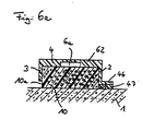
- Fig. 6a shows in cross section a further alternative of a profile 62.
- the through channel 6a is formed in that in the inner surface of the ceiling wall 4 facing the flow channel 6 there is arranged a groove running in the longitudinal direction of the profile 62, which is the free through channel 6a.
- the sealing medium is first introduced into this free passage 6a.
- the provided plastic foam 10 is impregnated with the sealing medium and then emerges in the region of the free longitudinal edges 5 in the desired manner.
- a web 46 can be provided as a horizontal extension of the side wall 3, a foam tape 47 being provided below the web, facing the concrete surface 1. This foam tape 47 is compressed somewhat when the profile 62 is fastened, but remains porous enough so that the sealing medium can escape through the foam tape 47 at the free end.
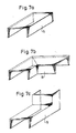
- the proposed sealing device is of a particularly simple construction and should therefore also provide correspondingly simple connecting elements between the abutting edges of two profiles 2, 12, 22, 42, 52, 62.
- Connecting elements can be connected, the dimensions of which are selected such that they can be put onto the profiles 2, 12, 22, 42, 52, 62 for example in a form-fitting and / or non-positive manner.
- FIG. 7a to 7e illustrate that straight connecting pieces 14 (FIG. 7a), flat corner brackets 15 (FIG. 7b), upright corner brackets 16 (FIG. 7c), T-pieces 17 (FIG. 7d), crossing pieces 18 ( 7e) are usable.
- the connecting elements can be fastened in the manner described above by means of screws, pins, nails or the like, preferably together with the profiles 2, 12, 22, 42, 52, 62 on the concrete surface 1 or on the profiles 2, 12, 22, 42, 52, 62 glued or held on it with locking means.
- connection elements are selected which have exactly the shape of the profiles 2, 12, 22, 42, 52, 62 in their cross-sectional shape.
- the profiles 2, 12, 22, 42, 52, 62 are then simply attached to the connecting elements, i.e. laid with them on bump.
- the connection point imaginable as a cross section can then simply be covered with an adhesive tape, so that the sealing device is prevented from slipping.
- the individual profiles 2, 12, 22, 42, 52, 62 and the connecting elements can be fastened in the usual manner.
- the adhesive tape can also be guided in multiple layers over the joint, the adhesive tape should extend up to the area of the free longitudinal edges 5 at the joint or shortly before. It is not recommended to completely wrap the joint or joint, as this would prevent the sealant from escaping in this area.
- Fig. 8 shows that for a particularly simple connection point for the pressing of the sealing medium in the sealing device, the abutting edge 19 of two profiles 2, 12, 22 can be arranged at a distance and that the dimensions of the profiles 2, 12 over the abutting edge region , 22 adapted press-in connector 23 is set in a form-fitting and / or non-positive manner, which can have, for example, the three-dimensional shape of the connecting piece 14, a movable, load-bearing, non-porous hose 21 being arranged on a hole 24 or, for example on a side wall 20 of the press-in connector 23 a connecting piece attached there is used, which is located in the area between the Butt edges 19 is located.
- profiles 42, 52, 62 can have a connection point designed according to FIG. 8, and that it is in particular also possible to use profiles 2, 12, 22 shown to be abutted directly onto the press-in connector 23 if the press-in connector 23 has the cross-sectional shape of the profiles 2, 12, 22 in an identical manner.
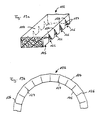
- the profiles 2, 12, 22 can be laid not only on flat surfaces 1, but also on curved or curved or round surfaces, e.g. of pipes or tubes which are surrounded or wrapped like a sleeve with the profiles 2, 12, 22.
- notches 25 are punched out of the side walls 3 of the profiles 2, 12, 22 or are omitted in the shaping of the profiles 2, 12, 22, which end with their notch tips 26 on the top wall 4 or shortly before the top wall 4, such as this is shown in Fig. 9a.
- Such a profile 2, 12, 22 can, according to FIG. 9b, be bent at least into an arc, preferably into a ring (not shown), because the material of the profiles 2, 12, 22, which preferably consists of plastic, is sufficiently flexible.
- the profile 2, 12, 22 is placed against the jacket surface, for example a pipe (not shown), and is bent accordingly and fastened on the pipe. It is expediently provided that the side edges 27 of the notches 25 abut against one another.
- a second concreting section is then concreted in the area of the profiles 2, 12, 22 around the pipe.
- the sealing medium is then fed into the interior of the profiles 2, 12, 22 via supply means (not shown), from which it can penetrate under the longitudinal edges 5 and / or through the abutting edge slots of the notches 25 into receivable cavities.
- the profiles 2, 12, 22, 42, 52, 62, the connecting elements 7a to 7e and the press-in connector can advantageously also be held on the concrete surface 1 by means of a bracket 31, a clamping bracket preferably being used which has a certain prestress against the profiles 2 , 12, 22, 42, 52, 62 or the connecting elements 7a to 7e or the press-in connector and thus prestressing them against the concrete surface 1.
- a bracket 31 can be designed in the form of a conventional pipe clamp, so that there is also a lateral fixation.
- the bracket 31 can be fastened to the concrete or to the concrete surface 1 by means of a fastening element encompassing its fastening tab, in particular a washer, a pin or a nail - as shown or described for the fastening for the profiles 2, 12, 22.
- a bracket holder is preferred, in which the bracket 31 is secured by inserting it into a form-fitting holder.
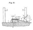
- An exemplary embodiment of this is shown in FIG. 10, the profiles 2, 12, 22 being shown by way of example, but the other profiles 52, 42, 62, the connecting elements 7a to 7e and the press-in connector 23 can also be secured in the same way.
- the bracket 31 engages over the profile 2, 12, 22 in the form of a pipe clamp and is bent approximately at the end of its bracket for this purpose so that the profile 2, 12, 22 is also held laterally.
- a holding arm 33 From the U-shaped mounting part 32 extends at a distance a from the concrete surface 1 horizontally or somewhat inclined, a holding arm 33 which continues into a support arm 34 which wraps around a reinforcing bar 35 extending here perpendicular to the concrete surface 1 and, preferably obliquely to Holding arm 33 extending, which, the profile 2,12,22 facing side of the reinforcing bar 35 also wraps. So the one across Wrap points 36, 37 having a distance b from one another to the concrete surface 1 represent abutments which secure the bracket 31 against lifting off from the profile 2, 12, 22.
- the bracket 31 is made of an elastic material, in particular spring steel, the holding and supporting arm 33, 34 being arranged at such a distance from the concrete surface 1 and the reinforcing bar 35 that the holding arm 33 is prestressed against the concrete surface 1.
- a distance c is provided between the end part 38 of the support arm 34 and the holding arm 33, which is greater than the cross-sectional dimension or the diameter of the reinforcing bar 35. This configuration makes it possible to thread the support arm 34 into the illustrated mounting point by reaching around and tilting it.
- the bracket 31 is preferably made of a round wire.
- the sealing device or the profile 2, 12, 22 is preferably arranged centrally between the reinforcing bars 35 shown. It is thus possible, alternatively or alternatively, to hold the same bracket 31 on the reinforcing bar 35 shown on the left in FIG. 10 in a positive and / or non-positive manner.
- FIG. 11 An alternative sealing device according to the invention is shown in FIG. 11, wherein a body 102 made of foam or a foam tape is used as the sealing device.
- the underside of the body 102 is placed on a hardened concrete surface 101 and mounted there.
- the assembly can be carried out using various mounting devices, an attachment using a screw 107 being shown as an alternative in FIG. 11.
- pins or nails can also be used, preferably together with washers.
- the screw head 108 should be of large area so that the largest possible part of the body 102 can be fixed via the screw head 108.
- the bracket The device is only inserted into the concrete surface 1 until its free end directed upwards, for example the screw head 108, comes to lie approximately in one plane with the upper side 104 of the body 102.
- the required passage or flow channel for the sealing medium is formed by the body 102 itself, the sealing medium being able to pass through its through pores and to exit into the joint area due to the porous nature of the body 102.
- the sealing medium emerges both in the area between the concrete surface 101 and the underside 105 of the body 102 and from its top 104 and its side surfaces 103 into the joint area.
- the body 102 can have a kind of coating or coating made of harder foam on its surface and its side surfaces 103, which is impermeable to the sealing medium.
- this coating is preferably not provided up to the underside 105, but ends shortly before.
- a type of exit area for the sealing medium is thereby created between the underside 105 and the end of the coating in the area of the side surfaces 103.
- the sealing medium can therefore no longer emerge in the areas that have the coating, but only in a lower area of the side surfaces 103, which is sufficient to seal the joint area.
- the body 102 can also advantageously be fastened with the aid of the mounting device described in FIG. 10, the function and design of which is to be expressly referred to here.
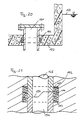
- FIG. 12 further, alternative mounting devices for the body 102 are shown.
- the screw 107 shown as well as pins or nails can be encompassed by a tubular spacer 110 in the shaft area, the length of which Cross-sectional height of the body 102 corresponds.
- a holder can also be made via a holder profile 109, which is U-shaped in cross section in the area of the body 102 and engages around the side surfaces 103 and the underside 104 of the body 102.
- a side leg of the support profile 109 is guided up to the concrete surface 101 and there bends approximately at right angles to form a web area which rests on the concrete surface 101. In this area, the mounting profile 109 can then be attached to the concrete surface 101, for example by means of a shot-in pin or nail.
- FIG. 12 also shows that the body 102 has a longitudinally extending, continuous recess in its cross-sectional interior, which serves as a free through channel 106a for the sealing medium.
- the sealing medium introduced into the body 102 will thus first fill the free through channel 106a of the body 102 and then exit through the porous material of the body 102 into the joint area.
- the cross-sectional interior of the body 102 can also have a plurality of continuous recesses running next to one another.
- FIGS. 11 and 12 show a preferred cross-sectional shape of the body 102 in the form of a cuboid and thus having a rectangular cross-section.
- the same advantageous properties of this sealing device can, however, also be achieved with bodies which have, for example, a trapezoidal or circular section-like cross section or also cross sections of any other design.
- a separate representation of alternative cross-sectional shapes of the sealing device was omitted. This possibility of alternatives Cross-sectional shapes of the sealing device also relate to the connecting elements subsequently described in FIGS. 13 to 17 and to the press-in connector body 123 shown in FIG. 18.
- connecting elements having the same cross-sectional shape and made of the same material are provided between their abutting edges, which are shown in FIGS. 13 to 17 and represent a non-exhaustive selection of preferred connecting elements.
- the task of these connection elements is not only the aforementioned connection of two bodies 102, but also the possibility of a change of direction with the aid of such connection elements.
- the bodies 102 are simply attached to the connecting elements so that their free connection ends lie flush against one another.
- 13 to 17 illustrate that straight connecting pieces 114 (FIG. 13), flat corner brackets 115 (FIG. 14), upright corner brackets 116 (FIG. 15), T-pieces 117 (FIG. 16) and crossing pieces 118 (FIG. 17) can be used, for example.
- the connecting elements are fastened in the manner already described by means of screws, pins, nails or mounting profiles, as are the bodies 102 on the concrete surface 1.
- connection of the bodies 102 to one another or the bodies 102 to the connecting elements at the respective joints is preferably carried out with the aid of an adhesive tape which is placed over the joint, the adhesive tape preferably covering only the top 104 and the side surfaces 103, the adhesive tape on the Side surfaces 103 can end at a distance from the concrete surface 101, so that the sealing medium can also emerge from the area of the joint in this area.
- the adhesive tape also serves primarily to prevent cement slurry and small particles from penetrating into the joint area during the concreting process.
- a Einpreßstutz stresses 123 is shown, on the an elastic, load-bearing, non-porous hose 121 is arranged in the area 124 on one side surface 102.
- This hose 121 serves as a filler neck for the sealing medium and is arranged outside the second concrete section or outside its formwork with its free end.
- the hose 121 preferably ends in the cross-sectional interior of the press-fit connector body 123 or in a free through channel 106a, if such should be provided.
- the sealing device will preferably have a further press-in connector 123 at another point, in particular in the end region of the sealing device, with which it can be checked whether the sealing medium has also penetrated the entire sealing device during the pressing in. In order to have several control points or press-in points for the sealing medium, a plurality of such press-in connector bodies 123 can also be provided.
- the body 102 can not only be laid on flat concrete surfaces, but also curved or circular surfaces, e.g. surrounded by pipes or tubes, cuff-like or follow curved concrete surfaces.
- curved or circular surfaces e.g. surrounded by pipes or tubes, cuff-like or follow curved concrete surfaces.
- V-shaped, notch-like incisions extending over their entire cross-sectional width are provided, as shown in FIG. 19a. These incisions represent notches 125, with their respective notch tip 126 ending somewhat below the cross-sectional height or the top 104 of the body 102.
- Such a body 102 having notches 125 can then, as shown in FIG. 19b, either follow an arcuate course or be bent into a ring (not shown) since the body 102 is sufficiently flexible.
- the body 102 is then placed, for example, against the lateral surface of a tube (not shown) and bent accordingly and then also fastened on the tube.
- the notch edge surfaces 127 touch or abut each other when the underside 105 abuts, for example, the pipe surface. This ensures that the then ring-shaped body 102 continues to be a continuous foam tape and has no imperfections into which the concrete of the second concreting section can penetrate and would thus prevent the sealing medium from penetrating.
- the body 102 without arranging notches 125 in order to adapt it to curved concrete surfaces 101 or to place it in a ring or cuff-like manner around circular bodies.
- the foam or the filter foam of the body 102 can be compressed for this bend without the passage pores required for the passage of the sealing medium being closed by the compression of the body 102.
- the sealing medium is fed or pressed into the body 102 via supply means, not shown, from which it can then penetrate into the cavities of the joint area to be filled in a sealing manner.
- a preferred attachment of the body 102 or the connecting elements or the press-fit connector body 123 is carried out on circular elements with an endless rubber band, in that the rubber band is stretched over the upper side, for example of the body 102 or other elements mentioned.
- the rubber band then ensures a tight hold of the ring-shaped sealing device on the corresponding circular element.
- the width of the rubber band can preferably be less than the cross-sectional width of the top 104 of the body 102, so that sufficient sealing medium can also escape into the joint area to be sealed in the area of the top 104.
- FIG. 20 shows a preferred use of the body 102 and / or its connecting elements or the press-in connector body 123 for sealing a groundwater relief connector 131.
- the body 102 is provided with notches 125 in the manner shown in FIGS. 19a and 19b.
- the body 102 surrounds the groundwater relief nozzle 131 in a ring-like manner the area in which the groundwater relief port 131 penetrates the bottom plate 132, which is made of concrete. This location in the base plate 132 is particularly at risk from penetrating groundwater or moisture, in particular if, as shown, the groundwater level 133 lies above the base plate 132.
- the body 102 Before concreting the floor slab 132 - with an artificially lowered groundwater table 133 - the body 102 is placed in a ring around the groundwater relief connection 131 and fastened there, for example, with the rubber band mentioned. After the base plate 132 has been concreted, the sealing medium is pressed into the body 102 via previously arranged filling devices or with the aid of the method according to claim 46. The joint area between the groundwater relief connection 131 and the base plate 132 is completely sealed after the sealing medium has emerged from the body 102 into the cavities present there.
- Another preferred use of the body arises when sealing a joint area between a body, for example a pipe and a concrete section, if liquids are constantly or occasionally present on one side of the concrete section, as is the case, for example, in water basins with concrete walls.
- Pipes or other devices that are present on the water side can be surrounded by the body 102 and, by subsequently injecting the sealing medium into the body 102, securely seal the joint area which is susceptible to the ingress of water.
- FIG. 21 A further preferred use of the body 102 and / or the connecting elements and the press-in connector 123 is shown in FIG. 21, the body 102 serving there to seal a connection point between two pipes 134, 135.
- the tubes 134, 135 are placed against one another via a Z-shaped connection point 136.
- This connection point 136 is a weak point in pipelines with regard to the escape of media carried in the pipelines.
- the body 102 is attached directly to the connection point 136 so that it encompasses this connection point 136 in a ring-like manner.
- the body 102 is designed prior to attachment to the connection point 136 as shown in FIGS. 19a and 19b, or - without being provided with notches 125 - simply bent correspondingly in a ring-like manner.
- the body 102 is preferably attached to the connection point 136 using the rubber band mentioned.
- the pipe connection point 136 shown is generally surrounded by a medium, for example mortar or soil or the like.
- the connection point is sealed, ie the sealing medium is introduced into the body 102, preferably after the entire pipe connection has been completed, so that the connection point 136 may already be surrounded by a specific medium.
- the sealing medium is introduced into the body 102 in the manner explained for FIG. 20. Since in this case a seal is only necessary at the connection point 136 of the two pipes 134, 135, the top 104 and the side surfaces 103 can be sealed with, for example, an adhesive tape, since it is evident that an escape of the sealing medium is only necessary in the direction of the two pipes 134, 135.
- the upper side 104 can preferably be sealed by the arrangement of the rubber band.
- the body 102 is also advantageously suitable for sealing a pipe socket connection point, wherein the body 102 is preferably arranged obliquely to the pipe socket or its cross section is adapted to the pipe socket connection point, for example has a triangular cross section.
- sealing device 138 is shown schematically in the joint area, which was applied to the concrete surface 101 before the concrete wall 137 was encased and concreted. Instead of previously arranged filler necks, which as a rule produce hose-like connections to the sealing device, in the method according to the invention the sealing device 138 is concreted in without such or a similarly designed connection.
- connection points or bores 139 are preferably provided, so that the sealing medium can be introduced at several points and control points are present at which it can be checked whether the sealing medium also penetrates the entire sealing device.
- Control or entry points in the form of bores 139 are preferably arranged at the start or end area of the joint, as seen in the longitudinal direction. It is up to the local conditions whether the connection is preferably led horizontally or obliquely to the sealing device 138.
Abstract
Description
Die Erfindung betrifft eine Dichtungsvorrichtung für Betonfugen gemäß den Oberbegriffen der Ansprüche 1 und 33 sowie ein Verfahren zum Einbringen eines Dichtungsmediums in Dichtungsvorrichtungen, wie es in Anspruch 49 beschrieben ist.The invention relates to a sealing device for concrete joints according to the preambles of
Aus der CH-PS 600 077 ist eine Dichtungsvorrichtung in Form eines porösen Schlauches bekannt. Dieser Schlauch besteht aus einem Stützkörper in Form einer Schraubenfeder, der von einem ersten, geflochtenen Schlauch umgeben ist, welcher wiederum von einem äußeren, netzartigen, porösen Schlauch umfaßt ist. Nach dem Montieren dieser Dichtungsvorrichtung und dem Betonieren des zweiten Betonierabschnittes wird ein Dichtungsmedium in die schlauchartige Dichtungsvorrichtung gepreßt, die in Fehlstellen des Betons austreten soll.A sealing device in the form of a porous tube is known from CH-PS 600 077. This hose consists of a support body in the form of a helical spring, which is surrounded by a first, braided hose, which in turn is surrounded by an outer, mesh-like, porous hose. After this sealing device has been installed and the second concreting section has been concreted, a sealing medium is pressed into the hose-like sealing device, which is to emerge from defects in the concrete.
Bei dieser bekannten Dichtungsvorrichtung ist es von Nachteil, daß die Verlegung aufwendig ist und die verlegten Schläuche beim Betonieren verdrängt oder zerdrückt werden können und/oder reißen. Ferner kann sich das poröse Schlauchmaterial durch Betonschlämme zusetzen, so daß ein Austreten des Dichtungsmediums nicht mehr möglich ist. Darüber hinaus sind die Herstellungskosten solcher Schläuche teuer.In this known sealing device it is disadvantageous that the laying is complex and the laid hoses can be displaced or crushed and / or tear during concreting. Furthermore, the porous hose material can become clogged by concrete sludge, so that it is no longer possible for the sealing medium to escape. In addition, the manufacturing costs of such hoses are expensive.
Den Nachteil des Verstopfens des Schlauchkörpers versucht die Dichtungsvorrichtung gemäß des DE-GM 83 35 231 zu beheben, indem zwischen dem Stützkörper in Form einer Schraubenfeder und dem äußeren netzwerkartigen Schlauch ein non-woven Material eingebracht wird, welches flüssigkeitsdurchlässig, aber für feine Betonteilchen undurchlässig ist.The sealing device according to DE-GM 83 35 231 tries to remedy the disadvantage of the hose body becoming blocked by introducing a non-woven material between the support body in the form of a helical spring and the outer network-like hose, which material is permeable to liquid but impermeable to fine concrete particles .
Der Nachteil des sich Zusetzens des netzartigen Schlauches kann durch die Anordnung des non-woven Materials möglicherweise behoben werden, jedoch verbleiben weiterhin die oben geschilderten Nachteile bei der Verwendung einer schlauchförmigen Dichtungsvorrichtung.The disadvantage of the mesh-like tube becoming clogged can possibly be eliminated by the arrangement of the non-woven material, but the disadvantages described above remain when using a tubular sealing device.
Schließlich ist aus der DE-GM 86 08 396 eine weitere Dichtungsvorrichtung in Form eines Injektionsschlauches bekannt, die einerseits den Nachteil des Positionierens des Schlauches durch am Schlauchkörper vorgesehene Laschen beheben will und andererseits eine Sollbruchstelle in Längsrichtung des schlauchartigen Körpers vorschlägt, durch welches das Dichtungsmedium in den Beton austreten soll. Die grundsätzlichen Vorteile des Injektionsschlauches sollen aber weiterhin erhalten bleiben.Finally, another sealing device in the form of an injection hose is known from DE-GM 86 08 396, which on the one hand wants to eliminate the disadvantage of positioning the hose by means of tabs provided on the hose body and on the other hand suggests a predetermined breaking point in the longitudinal direction of the hose-like body through which the sealing medium flows the concrete should leak. However, the basic advantages of the injection hose are to be retained.
Auch bei dieser bekannten Dichtungsvorrichtung bleiben weiterhin die Nachteile des Zerdrückens und/oder Zerreißens des Injektionsschlauches bestehen und auch der Nachteil, daß das Verlegen des Injektionsschlauches außerordentlich arbeitsintensiv ist. Zudem ist die Herstellung solcher Injektionsschläuche teuer.In this known sealing device, too, the disadvantages of crushing and / or tearing the injection hose remain and also the disadvantage that the laying of the injection hose is extremely labor-intensive. In addition, the production of such injection hoses is expensive.
Allen bekannten Dichtungsvorrichtungen ist es gemeinsam, daß das Dichtungsmedium direkt in den Schlauchanfang bzw. das Schlauchende eingepreßt wird. Schlauchanfang sowie Schlauchende müssen dabei nach Abschluß der Betoniermaßnahmen im Fugenbereich von außen frei zugänglich sein.It is common to all known sealing devices that the sealing medium is pressed directly into the beginning or end of the hose. The start and end of the hose must be freely accessible from the outside after completion of the concreting measures in the joint area.
Diese Art des Einbringens des Dichtungsmediums hat einerseits den Nachteil, daß die Betonschalung Aussparungen für die Schlauchenden aufweisen muß, wodurch sich die Schalungsarbeiten erhöhen. Weiterhin kann es beim Einschalen oder Betonieren passieren, daß die Schlauchenden beschädigt werden, wodurch ein Eindringen des Dichtungsmediums erschwert wird oder nur mit aufwendigen Zusatzmaßnahmen möglich ist.This type of introduction of the sealing medium has the one hand Disadvantage that the concrete formwork must have recesses for the hose ends, which increases the formwork work. Furthermore, it can happen during formwork or concreting that the hose ends are damaged, which makes penetration of the sealing medium difficult or is only possible with complex additional measures.
Es ist Aufgabe der vorliegenden Erfindung, eine Dichtungsvorrichtung gemäß dem Oberbegriff der Ansprüche 1 und 33 anzugeben, bei welcher ein sicheres Positionieren der Dichtungsvorrichtung möglich, ein Zerstören oder Beschädigen derselben verhindert und eine kostengünstige, einfache zu verlegende Dichtungsvorrichtung geschaffen wird, mit der ein zuverlässiges Abdichten von Fugen, insbesondere Betonfugen, gewährleistet ist.It is an object of the present invention to provide a sealing device according to the preamble of
Ferner soll ein Verfahren angegeben werden, mit welchem das Dichtungsmedium auf einfache Weise, sicher und kostengünstig in Dichtungsvorrichtungen, insbesondere der vorgeschlagenen Art, eingebracht werden kann.Furthermore, a method is to be specified with which the sealing medium can be introduced into sealing devices, in particular of the proposed type, in a simple, safe and inexpensive manner.
Vorrichtungsmäßig wird in einer ersten Lösung die Aufgabe bei einer gattungsgemäßen Dichtungsvorrichtung durch die kennzeichnenden Merkmale des Anspruchs 1 gelöst.In terms of the device, the problem is solved in a first solution in a generic sealing device by the characterizing features of claim 1.
Die vorgeschlagene Dichtungsvorrichtung löst sich vollkommen von der bisherigen Verwendung schlauchartiger Dichtungsvorrichtungen und schlägt die Verwendung eines im Querschnitt offenen, haubenförmig ausgebildeten Profils vor. Das Profil wird mit den freien Längskanten seiner Seitenbereiche bzw. Seitenwandungen auf der Betonoberfläche aufsitzend montiert, so daß der freie Durchtritt bzw. Durchflußkanal zwischen dem Profil und der Betonoberfläche gebildet wird, wobei das Dichtungsmedium zwischen den freien Längskanten des Profils und der Betonoberfläche in den Fugenbereich austreten kann. Solche Profile sind - je nach Material - im Spritz- oder Extrudierverfahren schnell und kostengünstig herstellbar und können auf einfache Weise verlegt werden.
Als Dichtungsmedium werden beispielsweise Silikate oder erhärtende Ein- oder Merkomponenten-Kunststoff in flüssiger Konsistenz verwendet. Auch Kunstharz, insbesondere 2-Komponenten-Acrylharz, findet als Dichtungsmedium Verwendung sowie Bentonit- und/oder Zementmischungen.The proposed sealing device is completely detached from the previous use of hose-like sealing devices and suggests the use of a profile which is open in cross-section and is hood-shaped. The profile is mounted with the free longitudinal edges of its side areas or side walls seated on the concrete surface, so that the free passage or flow channel is formed between the profile and the concrete surface, the sealing medium between the free longitudinal edges of the profile and the concrete surface in the joint area can leak. Depending on the material, such profiles can be produced quickly and inexpensively by injection or extrusion and can be laid in a simple manner will.
For example, silicates or hardening one- or multi-component plastics in liquid consistency are used as the sealing medium. Synthetic resin, in particular 2-component acrylic resin, is also used as a sealing medium, as are bentonite and / or cement mixtures.
In vorteilhafter Weise ist das Profil, im Querschnitt gesehen, ein U-förmiges Profil mit einer Deckenwandung und zwei davon senkrecht abgehenden Seitenwandungen.Advantageously, the profile, seen in cross section, is a U-shaped profile with a top wall and two side walls extending vertically therefrom.
Die Stapelbarkeit der Profile bei Lagerhaltung kann dadurch verbessert werden, daß die Profile einen trapez - oder bogenförmigen Querschnitt aufweisen.The stackability of the profiles during storage can be improved in that the profiles have a trapezoidal or arched cross section.
Eine vorteilhafte Befestigung des Profils erfolgt durch einen oder mehrere, quer zur Längsachse des Profils dieses durchfassende und in den Beton einfassende Schrauben, Stifte oder Nägel.An advantageous fastening of the profile is carried out by one or more screws, pins or nails, which encompass the transverse axis of the profile and encase it in the concrete.
Die Befestigung der Profile kann vorzugsweise dadurch erhöht werden, daß die Schraube oder der Nagel sich durch ihre Köpfe, vorzugsweise über eine Unterlagscheibe, auf dem Deckenbereich bzw. der Deckenwandung des Profils abstützen, mit dem Schaft ein Loch in der Deckenwandung durchgreifen und in die Betonoberfläche, gegebenenfalls in einen darin eingesetzten Dübel einfassen.The fastening of the profiles can preferably be increased in that the screw or the nail is supported by their heads, preferably via a washer, on the ceiling area or the ceiling wall of the profile, with the shaft reaching through a hole in the ceiling wall and into the concrete surface , if necessary, enclose in a dowel inserted therein.
Eine schnelle Montage des Profils ist durch ein Einschießen des Stiftes oder des Nagels vorteilhafterweise möglich.A quick assembly of the profile is advantageously possible by shooting in the pin or the nail.
Ein Abstützen der Deckenwandung wird durch eine Einspannung der Deckenwandung zwischen dem Kopf und dem Schacht ermöglicht. Die Einspannung erfolgt dabei vorzugsweise über eine Kontermutter an der Schraube, am Stift oder am Nagel.Supporting the ceiling wall is made possible by clamping the ceiling wall between the head and the shaft. The clamping is preferably carried out via a lock nut on the screw, pin or nail.
Eine weitere vorteilhafte Art der Abstützung der Deckenwandung erfolgt über einen Abstandhalter, der zwischen der Betonoberflä che und der Innenfläche der Deckenwandung angeordnet ist.Another advantageous way of supporting the ceiling wall is via a spacer, which is between the concrete surface che and the inner surface of the ceiling wall is arranged.
Die Herstellung der Profile ist auch insbesondere deshalb günstig, weil das gesamte Profil aus ein und demselben Material besteht.The production of the profiles is also particularly favorable because the entire profile consists of one and the same material.
Vorteilhafterweise können an den Längskanten auch Dichtlippen, bevorzugt einstückig, angeformt sein, die das Austreten des Dichtungsmediums ebenfalls erleichtern.Advantageously, sealing lips, preferably in one piece, can also be formed on the longitudinal edges, which also facilitate the escape of the sealing medium.
Die Dichtlippen sind dabei vorzugsweise elastisch, insbesondere aus weichem Kunststoff oder Gummi oder dergleichen ausgebildet, was das Austreten des Dichtungsmediums ebenfalls erleichtert.The sealing lips are preferably elastic, in particular made of soft plastic or rubber or the like, which also facilitates the escape of the sealing medium.
Mit Vorteil sind an den Längskanten des Profils, im Querschnitt gesehen, horizontal verlaufende, sich vom Profil wegerstreckende Stege mit einem auf der der Betonoberfläche zugewandten Stegfläche angeordneten Schaumstoffband vorgesehen. Die Aufständerung des Profils über die mit einem Schaumstoffband versehenen Stege sorgen einerseits für ein verbesserten Aufliegen der Profile auf der Betonoberfläche und andererseits für einen vergrößerten Austritt des Dichtmediums im Bereich der Längskanten des Profils. Das Austreten des Dichtungsmediums wird dabei durch die porösen Eigenschaften des Schaumstoffbandes ermöglicht. Darüber hinaus können die Profile auch im Stegflächenbereich über geeignete Haltemittel auf der Betonoberfläche befestigt werden.On the longitudinal edges of the profile, viewed in cross section, it is advantageous to provide horizontally extending webs extending from the profile with a foam tape arranged on the web surface facing the concrete surface. The elevation of the profile over the webs provided with a foam tape ensures, on the one hand, that the profiles lie better on the concrete surface and, on the other hand, that the sealing medium exits in the area of the longitudinal edges of the profile. The leakage of the sealing medium is made possible by the porous properties of the foam tape. In addition, the profiles can also be attached to the concrete surface in the area of the web surface using suitable holding means.
In vorteilhafter Weise ist es vorgesehen, daß der Innenraum des Profils mit einem offene Durchgangsporen aufweisenden Kunststoffschaum (Filterschaum) ausgefüllt ist, wobei das Dichtungsmedium im Durchflußkanal durch die Durchgangsporen des Kunststoffschaums leitbar ist. Der Kunststoffschaum stützt zusätzlich die Querschnittsform des Profils und sorgt dafür, daß der Verbrauch des verwendeten Dichtungsmediums wesentlich reduziert wird. Der Kunststoffschaum wird so gewählt, daß er genügend viele und große Durchgangsporen aufweist, um das Eintreten des Dichtungsmediums nicht zu behindern und gar zu verhindern.It is advantageously provided that the interior of the profile is filled with an open through-pored plastic foam (filter foam), the sealing medium in the flow channel being conductive through the through-pores of the plastic foam. The plastic foam also supports the cross-sectional shape of the profile and ensures that the consumption of the sealing medium used is significantly reduced. The plastic foam is chosen so that it has enough large and large passage pores to prevent the sealing medium from entering not to hinder and even prevent.
Vorzugsweise kann der Innenraum des Profils auch mit Kunststoffschaum ausgeschäumt oder ein Kunststoffschaumstreifen in den Innenraum eingepaßt werden. Auf diese vorgeschlagenen Arten kann der Innenraum schnell und kostengünstig mit dem Kunststoffschaum ausgefüllt werden.Preferably, the interior of the profile can also be foamed with plastic foam or a plastic foam strip can be fitted into the interior. In these proposed ways, the interior can be filled quickly and inexpensively with the plastic foam.
Vorteilhafterweise weist der Kunststoffschaum oder der Kunststoffschaumstreifen über die Längskanten der Profile hinaus einen Überstand auf. Dieser Überstand sorgt für einen vergrößerten Austrittsquerschnitt des Dichtungsmediums aus dem Profil.The plastic foam or the plastic foam strip advantageously has a protrusion beyond the longitudinal edges of the profiles. This protrusion ensures an enlarged cross section of the sealant from the profile.
Vorzugsweise ist in Längsrichtung des Profils unterhalb der Deckenwandung ein freier Durchgangskanal mit einer etwa in der Mitte der Höhe der Seitenwandungen angeordneten Bodenwandung vorgesehen, die einen Längsschlitz oder dergleichen Durchgänge aufweist, wobei unterhalb der Bodenwandung der Durchflußkanal mit Kunststoffschaum ausgefüllt ist. Durch diese Ausgestaltung des Profils wird ein freier Durchflußkanal gebildet, indem das Dichtungsmedium zunächst ungehindert eintreten und sich verteilen kann, um danach durch den Längsschnitt in den Kunststoffschaum und von da in den Fugenbereich auszutreten.Preferably, a free passage channel is provided in the longitudinal direction of the profile below the ceiling wall with a bottom wall arranged approximately in the middle of the height of the side walls, which has a longitudinal slot or similar passages, the flow channel being filled with plastic foam below the bottom wall. This configuration of the profile forms a free flow channel in which the sealing medium can initially enter and distribute unhindered, and then exit through the longitudinal cut into the plastic foam and from there into the joint area.
Der Durchgangskanal kann vorzugsweise auch dadurch gebildet werden, daß in der dem Durchflußkanal zugewandten Innenfläche des Profils, vorzugsweise in der Innenfläche der Deckenwandung, eine in Längsrichtung des Profils verlaufende Nut angeordnet ist. In dieser alternativen Ausgestaltung ergeben sich die vorgenannten Vorteile in gleicher Weise.The passage channel can preferably also be formed in that a groove running in the longitudinal direction of the profile is arranged in the inner surface of the profile facing the flow channel, preferably in the inner surface of the ceiling wall. In this alternative embodiment, the aforementioned advantages result in the same way.
Vorzugsweise sind zum Verbinden wenigstens zweier Profile zwischen den Stoßkanten der Profile dieselbe Querschnittsform der Profile aufweisende Verbindungselemente, vorzugsweise ebenfalls aus Kunststoff, vorgesehen. Mit Hilfe solcher Verbindungselemente können die Profile in beliebigen Richtungen auf der Betonoberflä che angeordnet werden.For connecting at least two profiles between the abutting edges of the profiles, connecting elements having the same cross-sectional shape of the profiles, preferably also made of plastic, are provided. With the help of such connecting elements, the profiles can be placed in any direction on the concrete surface che be arranged.
Vorzugsweise handelt es sich bei den Verbindungselementen um gerade Verbindungsstücke, ebene Eckwinkel, Hochkant-Eckwinkel, T-Stücke oder Kreuzungsstücke. Mit Hilfe der vorgeschlagenen Verbindungselemente können die wesentlichsten Richtungsänderungen beim Verlegen der Profile erfolgen.The connecting elements are preferably straight connecting pieces, flat corner angles, upright corner angles, T-pieces or crossing pieces. With the help of the proposed connecting elements, the most important changes in direction can be made when laying the profiles.
Vorteilhafterweise sind die Verbindungselemente auf die Profile stülpbar und vorzugsweise form- und kraftschlüssig daran gehalten. Die Verbindung der einzelnen Profile über die Verbindungselemente erfolgt somit auf einfache Weise und der vorgeschlagene Anschluß sorgt dafür, daß kein Dichtungsmedium im Stoßbereich aus den Profilen austreten kann.Advantageously, the connecting elements can be slipped onto the profiles and are preferably held thereon in a positive and non-positive manner. The connection of the individual profiles via the connecting elements is thus carried out in a simple manner and the proposed connection ensures that no sealing medium can emerge from the profiles in the joint area.
In vorteilhafter Weise sind die Verbindungselemente zusammen mit den Profilen auf die Betonoberfläche schraubbar. Somit muß an der Stoßstelle nur eine Halterung für Profil und Verbindungselement verwendet werden.The connecting elements can advantageously be screwed onto the concrete surface together with the profiles. Thus, only a bracket for profile and connecting element must be used at the joint.
Zum Verbinden der Profile untereinander oder der Profile mit den Verbindungselementen ist an den Stoßstellen ein undurchlässiges Klebeband vorgesehen, um zu verhindern, daß einerseits Zementschlämme und andere Teilchen beim Betoniervorgang im Stoßbereich in die Profile eindringen und andererseits das Dichtungsmedium aus dem Decken- und Seitenwandungsbereich austritt, da es dort eigentlich nicht benötigt wird. Das Klebeband wird im Decken- und Seitenwandungsbereich des Stoßes angebracht und kann auch vor dem Abschluß der freien Längskanten enden, da ein verstärktes Austreten im unteren Bereich der Seitenwandungen durchaus erwünscht sein kann.
Die Stoßstellen können vorzugsweise auch geschweißt werden.To connect the profiles to one another or the profiles with the connecting elements, an impermeable adhesive tape is provided at the joints to prevent cement slurries and other particles from entering the profiles in the joint area during the concreting process and on the other hand the sealing medium escaping from the ceiling and side wall area. since it is actually not needed there. The adhesive tape is applied in the ceiling and side wall area of the joint and can also end before the free longitudinal edges are closed, since increased emergence in the lower area of the side walls may well be desirable.
The butt joints can preferably also be welded.
Mit Vorteil weisen das Profil oder die Verbindungselemente zum Injizieren des Dichtmediums einen Anschluß, insbesondere in Form eines Rohres oder eines nicht porösen Schlauches auf, welcher mit seinem freien Ende außerhalb des Fugenbereichs bzw. einer Schalung angeordnet ist. Es können demnach bestimmte Elemente der Dichtungsvorrichtung bereits mit einem solchen Anschluß versehen sein, so daß vor Ort eine solche Anschlußstelle nicht mehr geschaffen werden muß. Mit besonderem Vorteil kann jedoch das später beschriebene Verfahren zum Einbringen des Dichtungsmediums gemäß Anspruch 49 verwendet werden.Advantageously, the profile or the connecting elements for injecting the sealing medium have a connection, in particular in the form of a tube or a non-porous hose, which with its free end is arranged outside the joint area or a formwork. Accordingly, certain elements of the sealing device can already be provided with such a connection, so that such a connection point no longer has to be created on site. However, the method for introducing the sealing medium described later can be used with particular advantage.
Um Verformungen der Dichtungsvorrichtung um deren Längsachse zu ermöglichen und um sich gekrümmten Betonoberflächen anpassen zu können, ist es vorteilhafterweise vorgesehen, daß die Profile oder Verbindungselemente in den Seitenwandungen Kerben aufweisen, die mit ihren Ecken bzw. Kerbspitzen an der Deckenwandung bzw. kurz vor der Deckenwandung enden.In order to enable deformations of the sealing device about its longitudinal axis and to be able to adapt to curved concrete surfaces, it is advantageously provided that the profiles or connecting elements in the side walls have notches with their corners or notch tips on the ceiling wall or just before the ceiling wall end up.
In einer vorteilhaften Ausgestaltungsform der Erfindung sind die Profile oder Verbindungselemente um ihre Längsachse gebogen und auf einer gekrümmten Betonoberfläche oder auf einem bogen- bzw. kreisförmigen Körper, beispielsweise einem Rohr, befestigt, wobei die Seitenkanten der Kerben gegeneinander stoßen und die Kerben somit geschlossen sind, wenn die Längskanten der Seitenwandungen auf der Betonoberfläche oder dem Körper aufliegen. Mit Hilfe dieser Ausgestaltungsform kann die Dichtungsvorrichtung nicht nur an gekrümmten Betonoberflächen, sondern sogar an bogen- bzw. kreisförmigen Körpern angeordnet werden. Wichtig ist dabei, daß bei einem Anliegen der Längskanten auf der Betonoberfläche oder der Oberfläche des entsprechenden Körpers die Kerben vollständig geschlossen sind. Die Kerben können dabei zusätzlich mit einem Klebeband abgedichtet werden.In an advantageous embodiment of the invention, the profiles or connecting elements are bent around their longitudinal axis and fastened on a curved concrete surface or on an arched or circular body, for example a pipe, the side edges of the notches abutting one another and the notches thus being closed, if the longitudinal edges of the side walls lie on the concrete surface or the body. With the help of this embodiment, the sealing device can be arranged not only on curved concrete surfaces, but even on curved or circular bodies. It is important that the notches are completely closed when the longitudinal edges lie against the concrete surface or the surface of the corresponding body. The notches can also be sealed with an adhesive tape.
Eine vorteilhafte Art der Befestigung des Profils erfolgt dadurch, daß das Profil und/oder ein Verbindungselemente durch einen rohrschellenförmigen Bügel gehalten sind.An advantageous way of fastening the profile is that the profile and / or a connecting elements are held by a tubular clamp-shaped bracket.
Das Befestigen, beispielsweise an einer Bewehrungsstange, erfolgt vorzugsweise dadurch, daß der Bügel am freien Ende seines sich etwa parallel oder geringfügig geneigt zur Betonoberfläche erstreckenden Haltearms eine Steckvorrichtung zum Anstecken, beispielsweise an einer Bewehrungsstange, aufweist.The attachment, for example to a reinforcement bar, is preferably carried out by the bracket at the free end of itself approximately parallel or slightly inclined to the concrete surface extending arm has a plug-in device for plugging, for example on a reinforcing bar.
In einer besonderen Ausgestaltungsform ist die Steckvorrichtung durch eine Biegung des Haltearms um etwa 360° unter schrägem Verlauf, vorzugsweise zu der das zu haltende Profil abgewandten Seite hin des so gebildeten Stützarms gebildet, wobei der Biegungsdurchmesser und der Abstand des Anfangsbereichs vom Endbereich der Biegung größer ist als der Durchmesser der Bewehrungsstange. Die vorgeschlagene Halteeinrichtung kann somit auf einfache Weise sicher und unverrückbar angeordnet werden.In a special embodiment, the plug-in device is formed by a bending of the holding arm by approximately 360 ° with an oblique course, preferably to the side of the support arm formed in this way, the side facing away from the profile to be held, the bending diameter and the distance of the starting area from the end area of the bend being greater than the diameter of the reinforcing bar. The proposed holding device can thus be arranged safely and immovably in a simple manner.
Der Federbügel ist dabei vorzugsweise aus elastisch biegbarem Material, insbesondere Federstahl, um etwaige Toleranzen ausgleichen zu können.The spring clip is preferably made of elastically bendable material, in particular spring steel, in order to be able to compensate for any tolerances.
Vorzugsweise ist der Bügel dabei aus rundem Draht gebogen, der sich entsprechend leicht und einfach in die gewünschte Form bringen läßt.Preferably, the bracket is bent from round wire, which can be easily and easily brought into the desired shape.
Eine weitere vorrichtungsgemäße Lösung der gestellten Aufgabe erfolgt bei einer gattungsgemäßen Dichtungsvorrichtung durch die kennzeichnenden Merkmale des Anspruchs 33.Another device-based solution to the object is achieved in a generic sealing device by the characterizing features of
Die Dichtungsvorrichtung besteht dabei aus einem, im Querschnitt bevorzugt rechteckigen Körper aus einem Durchgangsporen aufweisenden Schaumstoff (Filterschaum) bzw. einem Schaumstoffband, welcher auf die Betonoberfläche aufgelegt und dort montiert wird, so daß der Durchtritt bzw. Durchflußkanal durch den Körper selbst gebildet wird und das Dichtungsmedium aus den Durchgangsporen in den Fugenbereich austritt.The sealing device consists of a preferably cross-sectionally rectangular body made of a passage pores foam (filter foam) or a foam tape, which is placed on the concrete surface and mounted there, so that the passage or flow channel through the body itself is formed and that Sealing medium emerges from the passage pores into the joint area.
Der Körper kann dabei im Querschnitt gesehen auch andere Formen aufweisen, beispielsweise eine Trapezform oder eine gebogene oder eine Kreissegmentform. Dadurch, daß das Dichtungsmedium nicht nur im Bereich der Aufstandsfläche des Schaumstoffbandes in den Fugenbereich austritt, sondern auch aus dessen Seiten- und Deckenbereich, wird ein hoher Abdichtungsgrad im Bereich der Betonfuge erreicht. Als Eintrittsöffnung für das Dichtungsmedium kann dabei beispielsweise ein schlauchartiger Hohlkörper vorgesehen sein, der mit einem Ende in den Körper eingesetzt ist und mit dem anderen Ende außerhalb des zweiten Betonierabschnitts bzw. dessen Schalung angeordnet ist. Mit besonderem Vorteil kann jedoch das später beschriebene Verfahren zum Einbringen des Dichtungsmediums gemäß Anspruch 49 verwendet werden.In cross-section, the body can also have other shapes, for example a trapezoidal shape or a curved or a circular segment shape. The fact that the sealing medium A high degree of sealing in the area of the concrete joint is achieved not only in the area of the contact area of the foam tape in the joint area, but also from its side and ceiling area. A hose-like hollow body can be provided as the inlet opening for the sealing medium, for example, which is inserted into the body at one end and is arranged at the other end outside the second concreting section or its formwork. However, the method for introducing the sealing medium described later can be used with particular advantage.
Es versteht sich dabei, daß der verwendete Schaumstoff bzw. das verwendete Schaumstoffband einerseits genügende Porosität für den Durchtritt des Dichtungsmediums aufweist und andererseits von einer Konsistenz ist, die ein Zusammendrücken des Schaumstoffs bzw. des Schaumstoffbandes durch den aufgebrachten Beton weitgehendst vermeidet. Als Dichtungsmedium werden beispielsweise Silikate oder erhärtende Ein- oder Mehrkomponenten-Kunststoff in flüssiger Konsistenz verwendet. Auch Kunstharz, insbesondere 2-Komponenten-Acrylharz, findet als Dichtungsmedium Verwendung sowie Bentonit- und/oder Zementmischungen.It goes without saying that the foam or the foam tape used on the one hand has sufficient porosity for the passage of the sealing medium and on the other hand is of a consistency that largely avoids compression of the foam or the foam tape by the applied concrete. For example, silicates or hardening single- or multi-component plastic in liquid consistency are used as sealing medium. Synthetic resin, in particular 2-component acrylic resin, is also used as a sealing medium, as are bentonite and / or cement mixtures.
Die Befestigung des Körpers auf der Betonoberfläche erfolgt vorteilhafterweise durch einen oder mehrere, quer zu seiner Längsachse durchfassende und in den Beton einfassende, bevorzugt Unterlagscheiben aufweisende Stifte, Schrauben oder Nägel. Durch das Einbringen von Dübeln in die Betonoberfläche oder durch eine vorbestimmte Einstellung von Schußapparaten wird gewährleistet, daß die vorgenannten Halterungsmitteln nur soweit in die Betonoberfläche eingreifen, daß ihr Kopfbereich in etwa mit der Oberfläche des Körpers in einer Ebene nach dem Einbringen liegt.The body is advantageously fastened to the concrete surface by means of one or more pins, screws or nails which extend transversely to its longitudinal axis and surround the concrete and preferably have washers. The introduction of dowels in the concrete surface or by a predetermined setting of shooting devices ensures that the above-mentioned holding means only engage in the concrete surface to such an extent that their head region lies approximately in a plane with the surface of the body after the introduction.
Die gewünschte Endlage der Stifte, Schrauben oder Nägel kann durch die Verwendung von rohrförmigen Abstandhaltern erreicht werden, welche die Halterungsmitteln umgreifen, wobei die Länge der Abstandhalter in etwa der Querschnittshöhe des Körpers entspricht. Der Abstandhalter sorgt dann dafür, daß die Halterungsmittel nicht zu tief in den Körper eindringen.The desired end position of the pins, screws or nails can be achieved by using tubular spacers which encompass the holding means, the length of the spacers being approximately the cross-sectional height of the body corresponds. The spacer then ensures that the holding means do not penetrate too deep into the body.
Eine andere bevorzugte Halterung des Körpers kann auch durch ihn umfassende Halterungsprofile erfolgen, die auf der Betonoberfläche montiert sind. Bei den Halterungsprofilen kann es sich dabei um Metall- oder Kunststoffbänder handeln, die den Querschnittsumfang des Körpers ganz oder teilweise umgreifen, wobei die Halterungsprofile mit einem freien Ende auf der Betonoberfläche angeordnet sind, so daß die Halterungseinrichtung den Körper auf der Betonoberfläche festhält bzw. festklemmt, ohne jedoch den Querschnitt des Körpers an der Haltestelle wesentlich zu verringern.Another preferred mounting of the body can also be carried out by mounting profiles comprising it, which are mounted on the concrete surface. The support profiles can be metal or plastic straps that completely or partially encompass the cross-sectional circumference of the body, the support profiles being arranged with a free end on the concrete surface, so that the support device holds or clamps the body on the concrete surface without significantly reducing the cross section of the body at the bus stop.
Um den Duchtritt bzw. Durchfluß des Dichtungsmediums zu erleichtern, kann im Querschnittsinneren des Körpers eine in Längsrichtung verlaufende, durchgehende Ausnehmung vorgesehen sein, die als Durchgangskanal für das Dichtungsmedium dient. Beim Einbringen des Dichtungsmediums wird der Durchgangskanal zunächst gefüllt und anschließend durchdringt das Dichtungsmedium den Körper, bis es nach außen in den Betonbereich, die vorhandenen Fugen verschließend, austritt.In order to facilitate the passage or flow of the sealing medium, a continuous recess running in the longitudinal direction can be provided in the cross-sectional interior of the body and serves as a through-channel for the sealing medium. When the sealing medium is introduced, the through-channel is first filled and then the sealing medium penetrates the body until it emerges into the concrete area, closing off the existing joints.
Das Verbinden wenigstens zweier Körper an den Stoßkanten derselben erfolgt in vorteilhafter Weise durch dieselbe Querschnitts form aufweisende und aus gleichem Material bestehende Verbindungselemente.The connection of at least two bodies on the abutting edges of the same is advantageously carried out by the same cross-sectional shape and made of the same material connecting elements.
Diese Verbindungselemente können gerade Verbindungsstücke, ebene Eckwinkel, Hochkant-Eckwinkel, T-Stücke oder Kreuzungsstücke sein, so daß Richtungsänderungen beim Verlegen der Körper problemlos berücksichtigt werden können.These connecting elements can be straight connecting pieces, flat corner brackets, upright corner brackets, T-pieces or crossing pieces, so that changes in direction can be easily taken into account when laying the body.
Vorzugsweise ist zum Verbinden der Körper miteinander oder der Körper mit den Verbindungselementen an, den Stoßstellen ein Klebeband vorgesehen. Das Klebeband dient dabei vornehmlich zur Lagesicherung der Körper und kann vorzugsweise nur auf der von der Betonoberfläche abgewandten Seite der Körper angebracht sein und im oberen Bereich der Seitenteile der Körper, so daß auch an der Stoßstelle trotz, Klebeband genügend Dichtungsmaterial austreten kann.An adhesive tape is preferably provided to connect the bodies to one another or the body to the connecting elements at the joints. The tape is used primarily for Securing the position of the body and can preferably be attached only on the side of the body facing away from the concrete surface and in the upper region of the side parts of the body, so that sufficient sealing material can escape even at the joint, despite adhesive tape.
Zum Anpassen an gekrümmte Betonoberflächen oder gebogene bzw. kreisförmige Elemente ist es vorteilhafterweise vorgesehen, daß quer zur Längsachse der Körper oder der Verbindungselemente in Längsachsenrichtung nebeneinander angeordnete, V-förmige, kerbartige, über deren gesamte Querschnittsbreite verlaufende Einschnitte vorgesehen sind, deren Kerbspitzen etwas unterhalb der Querschnittshöhe der Körper oder der Verbindungselemente angeordnet sind. Die kerbartigen Einschnitte sollen also nur soweit geführt werden, daß der Körper noch einen zusammenhängenden Körper bildet.To adapt to curved concrete surfaces or curved or circular elements, it is advantageously provided that transverse to the longitudinal axis of the body or the connecting elements in the longitudinal axis direction side by side, V-shaped, notch-like incisions are provided, extending over their entire cross-sectional width, the notch tips slightly below that Cross-sectional height of the body or the connecting elements are arranged. The notch-like incisions should therefore only be made to such an extent that the body still forms a coherent body.
Vorzugsweise sind die Körper oder Verbindungselemente um ihre Längsachse gebogen und auf einer gekrümmten Betonoberfläche oder auf einem bogen- oder kreisförmigen Element, beispielsweise einem Rohr, befestigt, wobei die Seitenkantenflächen der Kerben gegeneinanderstoßen und die Kerben somit geschlossen sind, wenn die Unterseite des Körpers auf der Betonoberfläche oder dem Element anliegen. Auf diese Art und Weise können die Schaumstoffbänder auch gekrümmten bzw. gebogenen Verläufen folgen.Preferably, the bodies or fasteners are bent about their longitudinal axis and secured on a curved concrete surface or on an arc or circular element, for example a pipe, the side edge surfaces of the notches abutting one another and the notches thus being closed when the underside of the body is on the Concrete surface or the element. In this way, the foam strips can also follow curved or curved courses.
Es ist in vorteilhafter Weise auch möglich, die Körper oder Verbindungselemente um ihre Längsachse zu biegen, um sie auf einer gekrümmten Betonoberfläche oder auf einem bogen- bzw. kreisförmigen Element, beispielsweise einem Rohr, zu befestigen, ohne dabei kerbartige Einschnitte vorzusehen. Der aus dem Schaumstoff bzw. Filterschaum bestehende Körper wird sich in dem, der gekrümmten bzw. gebogenen Fläche zugewandten Bereich zusammendrücken, jedoch verhindert dieses Zusammendrücken das Austreten des Dichtungsmaterials nicht. Dies liegt daran, daß das für den Körper vorgesehene Material von einer solchen Beschaffen heit ist, daß selbst bei einem stärkeren Zusammenpressen des Materials die für das Durchtreten des Dichtungsmediums erforderlichen Durchgangsporen noch vorhanden sind.It is also advantageously possible to bend the bodies or connecting elements about their longitudinal axis in order to fix them on a curved concrete surface or on an arcuate or circular element, for example a pipe, without providing notch-like incisions. The body consisting of the foam or filter foam will compress in the area facing the curved or curved surface, but this compression does not prevent the sealing material from escaping. This is because the material intended for the body is of such a nature is that even with a stronger compression of the material, the passage pores required for the passage of the sealing medium are still present.
In vorteilhafter Weise sind die Körper und/oder Verbindungselemente mit einem endlosen Gummiband auf dem kreisförmigen Element gehalten, indem das Gummiband über die Oberseite der Körper bzw. Verbindungselemente gespannt ist. Diese einfache und schnelle Art der Befestigung des Körpers und/oder der Verbindungselemente sorgt für einen festen Sitz auf kreisförmigen oder gebogenen Elementen, ohne daß dabei andere Halterungsmittel verwendet werden müssen. Die Gummibänder können dabei vorzugsweise eine Querschnittsbreite aufweisen, die geringer oder wesentlich geringer ist als die Querschnittsbreite des bzw. der Körper, so daß ein Austreten des Dichtungsmediums auch an der Oberseite des Körpers nicht wesentlich behindert wird.The bodies and / or connecting elements are advantageously held on the circular element with an endless rubber band, in that the rubber band is stretched over the top of the bodies or connecting elements. This simple and quick way of fastening the body and / or the connecting elements ensures a firm fit on circular or curved elements without having to use other mounting means. The rubber bands can preferably have a cross-sectional width that is smaller or substantially smaller than the cross-sectional width of the body or bodies, so that leakage of the sealing medium is also not significantly hindered on the top of the body.
In einer ganz besonders vorteilhaften Ausgestaltung ist es vorgesehen, daß der Körper, im Querschnitt gesehen, auf seiner der Betonoberfläche abgewandten Oberseitenfläche und seinen Seitenflächen eine Art Überzug bzw. Beschichtung aus härterem, vorzugsweise für das Dichtmedium undurchlässigem Schaumstoff aufweist, wobei die Beschichtung im Bereich der Seitenflächen vorzugsweise vor der Unterseite bzw. Standfläche des Körpers endet, so daß der Durchgangsporen aufweisende Schaumstoff bzw. Filterschaum in den unteren Seitenbereichen ohne die Beschichtung ist. Der Körper soll in dieser vorzugsweisen Ausgestaltung demnach mittels der zusätzlich anzuordnenden Beschichtung in Teilen seiner Seitenbereiche und vor allem auf seiner Oberfläche eine zweite, äußere Schicht aufweisen, die einerseits einen Stützeffekt für den Körper darstellt und andererseits ein Austreten des in den Körper injizierten Dichtungsmediums aus den Bereichen verhindert, die die Beschichtung aufweisen. Das Dichtungsmedium soll nämlich insbesondere den Fugenbereich, d.h. den Bereich der Standfläche des Körpers, abdichten. Dadurch, daß die Beschichtung in den Seitenbereichen nicht bis zur Standfläche des Körpers heruntergezogen ist, sondern vor dieser und somit vor der Betonoberfläche endet, wird im Standbereich des Körpers in den unteren Seitenbereichen eine ausreichend große Austrittsfläche für das Dichtungsmedium geschaffen. Die Beschichtung kann dabei nachträglich auf den Körper aufgebracht sein oder zusammen mit dem Körper hergestellt werden. Es spielt dabei keine Rolle, ob der Körper, im Querschnitt gesehen, eine linear verlaufende Seitenkante oder durch das Aufbringen der Beschichtung einen Sprung aufweist. Der Schaumstoff bzw. der Filterschaum des Körpers ist von einer Materialbeschaffenheit, die auch bei hohen Drücken ein zu starkes Zusammendrücken des Körpers verhindert, so daß stets ein genügend großer Austrittsraum für das Dichtungsmedium vorhanden ist.In a very particularly advantageous embodiment, it is provided that the body, as seen in cross section, has on its top surface facing away from the concrete surface and its side surfaces a type of coating or coating of harder foam, which is preferably impermeable to the sealing medium, the coating in the area of the Side surfaces preferably end in front of the underside or standing surface of the body, so that the through-pored foam or filter foam in the lower side areas is without the coating. In this preferred embodiment, the body should therefore have a second, outer layer by means of the additional coating to be arranged in parts of its side areas and above all on its surface, which on the one hand represents a support effect for the body and on the other hand a leakage of the sealing medium injected into the body from the Prevents areas that have the coating. The sealing medium should in particular seal the joint area, ie the area of the base of the body. Because the coating in the side areas is not up to the footprint of the body is pulled down, but ends in front of this and thus in front of the concrete surface, a sufficiently large exit surface for the sealing medium is created in the lower side areas in the standing area of the body. The coating can be applied subsequently to the body or can be produced together with the body. It does not matter whether the body, seen in cross section, has a linear side edge or a crack due to the application of the coating. The foam or the filter foam of the body is of a material which prevents the body from being compressed too much, even at high pressures, so that there is always a sufficiently large outlet space for the sealing medium.
Der erfindungsgemäße aus Schaumstoff bzw. Schaumstoffband bestehende Körper wird dabei in vorteilhafter Weise zum Abdichten eines Grundwasser-Entlastungsstutzens verwendet. GrundwasserEntlastungsstutzen, die beispielsweise Bodenplatten durchdringen, wobei der Grundwasserspiegel über dem Niveau der Bodenplatte liegt, werden an der Verbindungsstelle Bodenplatte/Entlastungsstutzen mit dem Körper umwickelt bzw. umschlungen, so daß nach dem Einbringen des Dichtungsmediums in den Körper eine sichere Abdichtung gegen aufsteigendes Grundwasser an der vorgenannten Verbindungsstelle gewährleistet ist.The body according to the invention, consisting of foam or foam tape, is advantageously used for sealing a groundwater relief connection. Groundwater relief ports, which penetrate floor slabs, for example, with the groundwater level above the level of the floor slab, are wrapped or wrapped around the body at the base plate / discharge port connection point, so that after the sealing medium has been introduced into the body, a secure seal against rising groundwater at the aforementioned connection point is guaranteed.
Weiterhin kann der vorgeschlagene Körper mit Vorteil zum Abdichten eines Fugenbereichs zwischen einem Körper, beispielsweise einem Rohr, und einem Betonabschnitt verwendet werden, insbesondere dann, wenn auf einer Seite des Betonabschnitts ständig oder gelegentlich Flüssigkeiten vorhanden sind. So weisen beispielsweise mit Wasser gefüllte Betonbecken in den Betonwandungen Rohrdurchbrüche oder andere Einrichtungen, wie beispielsweise Scheinwerfer oder ähnliches auf, wobei der Fugenbereich zwischen den Betonwandungen und den darin eingesetzten Körpern sorgfältig abgedichtet werden muß, um ein Eindringen von Wasser in diesem Bereich zu vermeiden, was mit dem vorgeschlagenen Körper und einem anschließenden Injizieren des Dichtungsmediums sicher und zuverlässig bewerkstelligt werden kann.Furthermore, the proposed body can advantageously be used to seal a joint area between a body, for example a pipe, and a concrete section, in particular if liquids are constantly or occasionally present on one side of the concrete section. For example, water-filled concrete pools in the concrete walls have pipe openings or other devices, such as headlights or the like, whereby the joint area between the concrete walls and the bodies used therein must be carefully sealed in order to prevent water from penetrating into this area with the proposed Body and a subsequent injection of the sealant can be done safely and reliably.
Gleichermaßen vorteilhaft läßt sich der vorgeschlagene Körper zum Abdichten einer Verbindungsstelle zwischen zwei Rohren, auch bei einer Rohrmuffen-Verbindungsstelle, anwenden. Hier wird der Körper im Bereich des Spaltes zwischen den beiden miteinander verbundenen Rohren angeordnet, indem es um diesen Bereich herumgelegt wird und wie bei dem Entlastungsstutzen einen Ring um die Verbindungsstelle bildet. Nach dem Einbringen des Dichtungsmediums in den Körper ist die Verbindungsstelle so gesichert, daß eventuell austretende Flüssigkeit aus der Verbindungsstelle sicher zurückgehalten werden kann.Equally advantageously, the proposed body can be used to seal a connection point between two pipes, even with a pipe socket connection point. Here, the body is arranged in the area of the gap between the two pipes connected to one another by being placed around this area and forming a ring around the connection point, as in the relief connection. After the sealing medium has been introduced into the body, the connection point is secured in such a way that any escaping liquid can be safely retained from the connection point.
Die eingangs gestellte Aufgabe wird verfahrensgemäß durch die Merkmale des Anspruchs 49 gelöst.The object stated at the outset is achieved according to the method by the features of claim 49.
Ein wesentlicher Grundgedanke besteht dabei in der Erkenntnis, daß auf einen oder mehrere externe Anschlüsse zum Einbringen des Dichtungsmediums, die außerhalb des zweiten Betonierabschnitts bzw. der Schalung angeordnet sind, verzichtet werden kann, die Dichtungsvorrichtung also ohne Anschluß nach außen im Fugenbereich zwischen den beiden Betonierabschnitten angeordnet ist. Sämtliche bisher bekannte Dichtungsvorrichtungen und insbesondere die Dichtungsvorrichtungen gemäß Anspruch 1 und 33 können durch eine nachträgliche Verbindung zwischen einer Außenseite des Betons bzw. des zweiten Betonierabschnitts und den Dichtungsvorrichtungen mit einem Dichtungsmedium verfüllt werden. Bei dem Dichtungsmedium handelt es sich dabei z.B. um Silikate oder erhärtende Ein- oder Mehrkomponenten- Kunststoffe in flüssiger oder verpreßbarer Konsistenz. Auch Kunstharz, insbesondere 2-Komponenten-Acrylharz, kann als Dichtungsmedium verwendet werden sowie Bentonit- und/oder Zementmischungen.An essential basic idea here is the knowledge that one or more external connections for introducing the sealing medium, which are arranged outside the second concreting section or the formwork, can be dispensed with, i.e. the sealing device without a connection to the outside in the joint area between the two concreting sections is arranged. All previously known sealing devices and in particular the sealing devices according to
Die nachträgliche Verbindung wird beispielsweise insbesondere durch ein Bohren in den erhärteten Beton zwischen einer Außensei te des Betons und den Dichtungsvorrichtungen geschaffen. Es versteht sich dabei, daß die Bohrung soweit ausgeführt werden muß, daß der Durchflußkanal oder der Durchtritt der Dichtungsvorrichtung zugänglich wird. Durch die Verbindung bzw. das Bohrloch wird das Dichtungsmedium anschließend eingebracht bzw. eingepreßt. Vorteilhafterweise wird eine weitere Verbindung zu der Dichtungsvorrichtung geschaffen, durch welche beim Einpreßvorgang die Luft entweichen kann und die auch als Kontrollstelle dient, ob das Dichtungsmedium auch die gesamte Dichtungsvorrichtung durchdrungen hat. Es ist auch denkbar, eine größere Anzahl solcher Verbindungen zu schaffen und diese anschließend abzudichten, wenn das Dichtungsmedium aus den Verbindungsstellen austritt.The subsequent connection is made, for example, in particular by drilling into the hardened concrete between an outer sieve te of the concrete and the sealing devices. It goes without saying that the bore must be made so far that the flow channel or the passage of the sealing device is accessible. The sealing medium is then introduced or pressed in through the connection or the borehole. A further connection to the sealing device is advantageously created, through which the air can escape during the press-in process and which also serves as a control point as to whether the sealing medium has also penetrated the entire sealing device. It is also conceivable to create a larger number of such connections and then to seal them when the sealing medium emerges from the connection points.
Die Stelle, an welcher das Dichtungsmedium in die Dichtungsvorrichtung eingebracht wird, kann beliebig angeordnet sein, wohingegen als Kontrollstellen dienende weitere Verbindungsstellen am Anfang bzw. am Ende der Fuge angeordnet sein sollten, um zu kontrollieren, daß das Dichtungsmedium auch bis in die Endbereiche der Dichtungsvorrichtung eingedrungen ist.The location at which the sealing medium is introduced into the sealing device can be arranged in any way, whereas other connection points serving as control points should be arranged at the beginning or at the end of the joint in order to check that the sealing medium also extends into the end regions of the sealing device has penetrated.
Je nach den örtlichen Gegebenheiten kann die Verbindung horizontal oder von schräg oben oder schräg unten in Richtung der Dichtungsvorrichtung geschaffen werden. Vorzugsweise werden die Verbindungsstellen an vorbestimmten Positionen erfolgen, wobei vorher festgelegt werden kann, in welcher Höhe oder unter welchem Winkel und vor allem wie lange die Verbindungsstelle geschaffen werden muß, damit sichergestellt ist, daß die Dichtungsvorrichtung auch auf die gewünschte Weise getroffen bzw. angebohrt wird.Depending on the local conditions, the connection can be made horizontally or from obliquely above or obliquely below in the direction of the sealing device. The connection points are preferably made at predetermined positions, it being possible to determine beforehand at what height or at what angle and above all how long the connection point must be created, in order to ensure that the sealing device is also hit or drilled in the desired manner .
Mit dem vorgeschlagenen Verfahren zum Einbringen des Dichtungsmediums in Dichtungsvorrichtungen wird verhindert, daß die Schalung eine oder mehrere Durchbrechungen für vorher verlegte Anschlußöffnungen oder Anschlußstutzen aufweisen muß. Weiterhin wird verhindert, daß diese vorher geschaffenen Verbindungsstellen beim Einschalen oder Betonieren angerissen oder zerstört werden. Die Tragfähigkeit bzw. Sicherheit des durchbohrten Betons wird auch durch die Anordnung mehrerer Verbindungsstellen nicht herabgesetzt.The proposed method for introducing the sealing medium into sealing devices prevents the formwork from having one or more openings for previously laid connection openings or connecting pieces. It also prevents these previously created connection points from being torn or destroyed during formwork or concreting. The The load-bearing capacity or safety of the pierced concrete is not reduced by the arrangement of several connection points.
Die Erfindung soll anschließend anhand bevorzugter Ausführungsbeispiele schematisch und beispielhaft beschrieben werden. Es zeigen dabei:
- Fig. 1 perspektivisch einen Abschnitt einer ersten Ausführungs form der erfindungsgemäßen Dichtungsvorrichtung in Form eines Profils;
- Fig. 2 perspektivisch die Ausführungsform gemäß Fig. 1 mit Dichtlippen;
- Fig. 2a perspektivisch einen Abschnitt einer zweiten Ausführungsform der erfindungsgemäßen Dichtungsvorrichtung in Form eines Profils;
- Fig. 2b perspektivisch einen Abschnitt einer dritten Ausführungs form der erfindungsgemäßen Dichtungsvorrichtung in Form eines Profils;
- Fig. 3 perspektivisch einen Abschnitt einer vierten Ausführungsform der erfindungsgemäßen Dichtungsvorrichtung in Form eines Profils;
- Fig. 4 die Ausführungsform gemäß Fig. 3 mit Dichtlippen;
- Fig. 5 perspektivisch einen Abschnitt einer fünften Ausführungs form der erfindungsgemäßen Dichtungsvorrichtung in Form eines Profils;
- Fig. 6 die Ausführungsform gemäß Fig. 5 mit Dichtlippen;
- Fig. 6a perspektivisch einen Abschnitt einer 6. Ausführungsform der erfindungsgemäßen Dichtungsvorrichtung in Form eines Profils;
- Fig. 7a bis 7e Verbindungsstücke für Stoßkanten der erfindungsgemäßen Dichtungsvorrichtung in Form eines Profils;
- Fig. 8 einen Einpreßstutzen für die erfindungsgemäße Dichtungsvorrichtung in Form eines Profils;
- Fig. 9a/b die Ausbildung der erfindungsgemäßen Dichtungsvorrich tung in Form eines Profils als Manschette für rohrförmige Körper;
- Fig. 10 eine mittels eines Bügels gehaltene Dichtungsvorrichtung in Form eines Profils im Querschnitt;
- Fig. 11 perspektivisch einen Abschnitt einer ersten Ausführungsform der erfindungsgemäßen Dichtungsvorrichtung in Form eines Körpers aus Schaumstoff;
- Fig. 12 die Ausführungsform gemäß Fig. 1, jedoch mit zusätzlichem Durchgangskanal und alternativer Halterungsanordnung;
- Fig. 13
bis 17 Verbindungsstücke für Stoßkanten der erfindungsgemäßen Dichtungsvorrichtung in Form eines Körpers aus Schaumstoff; - Fig. 18 eine Einpreßstelle für die erfindungsgemäße Dichtungsvorrichtung in Form eines Körpers aus Schaumstoff;
- Fig. 19a/b die Ausbildung der erfindungsgemäßen Dichtungsvorrichtung in Form eines Körpers aus Kunststoff als Manschette für rohrförmige Körper;
- Fig. 20 die Verwendung der erfindungsgemäßen Dichtungsvorrichtung in Form eines Körpers aus Schaumstoff für einen Grundwasser-Entlastungsstutzen;
- Fig. 21 die Verwendung der erfindungsgemäßen Dichtungsvorrichtung in Form eines Körpers aus Schaumstoff für eine Rohr-Verbindungsstelle und
- Fig. 22 eine bildliche Darstellung des erfindungsgemäßen Verfahrens zum Einbringen eines Dichtungsmediums in Dichtungsvorrichtungen.
- Figure 1 is a perspective section of a first embodiment of the sealing device according to the invention in the form of a profile.
- FIG. 2 shows in perspective the embodiment according to FIG. 1 with sealing lips;
- 2a shows in perspective a section of a second embodiment of the sealing device according to the invention in the form of a profile;
- 2b shows a perspective section of a third embodiment of the sealing device according to the invention in the form of a profile;
- 3 is a perspective view of a section of a fourth embodiment of the sealing device according to the invention in the form of a profile;
- FIG. 4 shows the embodiment according to FIG. 3 with sealing lips;
- Figure 5 is a perspective section of a fifth embodiment of the sealing device according to the invention in the form of a profile.
- 6 shows the embodiment according to FIG. 5 with sealing lips;
- 6a shows in perspective a section of a 6th embodiment of the sealing device according to the invention in the form of a profile;
- 7a to 7e connecting pieces for abutting edges of the sealing device according to the invention in the form of a profile;
- 8 shows a press-in connector for the sealing device according to the invention in the form of a profile;
- 9a / b the formation of the sealing device according to the invention tion in the form of a profile as a sleeve for tubular bodies;
- 10 shows a sealing device in the form of a profile held in cross section by means of a bracket;
- 11 shows in perspective a section of a first embodiment of the sealing device according to the invention in the form of a body made of foam;
- FIG. 12 shows the embodiment according to FIG. 1, but with an additional through-channel and an alternative mounting arrangement;
- 13 to 17 connectors for butt edges of the sealing device according to the invention in the form of a body made of foam;
- 18 shows a press-in point for the sealing device according to the invention in the form of a body made of foam;
- 19a / b the design of the sealing device according to the invention in the form of a body made of plastic as a sleeve for tubular bodies;
- 20 shows the use of the sealing device according to the invention in the form of a body made of foam for a groundwater relief connection;
- Fig. 21 shows the use of the sealing device according to the invention in the form of a body made of foam for a pipe connection point and
- 22 shows a pictorial representation of the method according to the invention for introducing a sealing medium into sealing devices.
Die Dichtungsvorrichtung in Form von Profilen besteht gemäß Fig. 1 aus einem im Querschnitt U-förmigen Profil 2, welches auf eine erhärtete Betonoberfläche 1 montiert ist und eine Deckenwandung 4 und zwei Seitenwandungen 3 aufweist. Das Kunststoffprofil 2 wird derart auf die Betonoberfläche 1 montiert, daß die freien Längskanten 5 der Seitenwandungen 3 auf der Betonoberfläche 1 aufsitzen, so daß ein Durchflußkanal 6 zwischen der Betonoberflä che 1 und dem Profil 2 gebildet wird.1 consists of a cross-sectionally
Die Befestigung des Profils 2 auf der Betonoberfläche 1 kann mit Bügeln oder dergleichen erfolgen. Vorzugsweise wird jedoch eine einfache Verschraubung vorgesehen, bei der eine Schraube 7 sich mit ihrem Schraubenkopf 8, gegebenenfalls über eine nicht dargestellte Unterlagscheibe, auf der Deckenwandung 4 abstützt, mit ihrem Schaft ein Loch in der Deckenwandung 4 durchgreift und z.B. in einem im Beton angeordneten Dübel eingeschraubt ist. An Stelle einer Schraube kann auch ein Stift oder Nagel (nicht dargestellt) benutzt werden, der in den Beton eingeschlagen oder mittels eines Schußapparates eingeschossen ist, wobei der Stift oder Nagel das Profil 2 auch mit oder ohne Kopf sichern kann. Letzteres insbesondere dann, wenn er das Profil 2 klemmend durchfaßt (durchschießt). Damit lagert die erfindungsgemäße Dichtungsvorrichtung ortsfest und kann durch den Frischbeton des zweiten Betonierabschnitts nicht verdrängt werden. Das Profil 2 ist so ausreichend steif ausgeführt, daß es durch den aufgebrachten Frischbeton oder durch die Einwirkung der bei Benutzung eines Betonrüttlers auftretenden Kräfte nicht schädlich deformiert oder zerdrückt wird.The
In den Durchflußkanal 6 wird das Dichtungsmedium eingebracht, das durch die Wandungen des Profils 2 nicht entweichen kann, weil dessen Wandungen für das Dichtungsmedium undurchlässig sind. Das Dichtungsmedium kann aber zwischen den Längskanten 5 des Profils 2 und der Betonoberfläche 1 nach außen dringen, wobei es in der jeweiligen Umgebung, jeweils in den Bereichen der Wandanschlußstellen oder den Anschlußstellen des Profils 2 liegende undichte Bereiche bzw. für das Dichtungsmedium aufnahmefähige Bereiche abdichtet. Die Rauhigkeit der Betonoberfläche reicht normalerweise aus, genügend Auscrittsstellen für das Dichtungsmedium zur Verfügung zu stellen.In the
Eine Variante zeigt Fig. 2, wobei an den Längskanten 5 relativ weiche Dichtlippen 9, insbesondere einstückig, angeformt sind, die aus weichem Kunststoff oder Gummi oder dergleichen bestehen und den Austritt des Dichtungsmediums in aufnahmefähige Bereiche begünstigen.2 shows a variant, wherein relatively
In Fig. 2a ist ein Profil 42 mit einem trapezförmigen Querschnitt gezeigt, während das in Fig. 2b gezeigte Profil 52 einen bogenförmigen Querschnitt aufweist. Die Befestigung der beiden Profile 42,52 sowie die zusätzliche Anordnung der in Fig. 2 gezeigten Dichtlippen erfolgt in analoger Weise. Der Vorteil der Querschnittsformen der Profile 42,52 kann unter anderem darin gesehen werden, daß bei einer Lagervorhaltung solchermaßen ausgestaltete Profile 42,52 die Stapelbarkeit wesentlich erhöht wird, so daß Platz für die Lagerung eingespart werden kann. Auch bei diesen Profilen können die Seitenwandungen 43 bzw. 53 aus elastischerem Material bestehen als die entsprechenden Deckenwandungen 44 bzw. 54.FIG. 2a shows a
In den nachfolgenden Figuren wird als Ausführungsbeispiel stets ein Profil mit U-förmigem Querschnitt gezeigt. Es soll an dieser Stelle bemerkt werden, daß die vorteilhaften Ausgestaltungen, die in den nachfolgenden Figuren erläutert werden, auch für andere Querschnittsformen des Profils, insbesondere für die Querschnittsformen der Profile 42,52, verwendet werden können.In the following figures, a profile with a U-shaped cross section is always shown as an exemplary embodiment. It should be noted at this point that the advantageous configurations, which are explained in the following figures, can also be used for other cross-sectional shapes of the profile, in particular for the cross-sectional shapes of the
In den Fig. 3 und 4 ist der Durchflußkanal 6 jeweils mit einem Kunststoffstreifen bzw. einem Kunststoffschaum 10 ausgeschäumt, der offene Durchgangsporen aufweist, so daß das Dichtungsmedium im Durchflußkanal 6 durch die Durchgangsporen des Kunststoffschaums 10 geleitet wird. Anstelle eines ausgeschäumten Profils 12 kann zweckmäßigerweise ein Profil 12 verwendet werden, in welches der Kunststoffschaum in Form eines Kunststoffschaumstreifens eingepaßt, vorzugsweise eingeklebt ist. Vorteilhaft ist dabei ein Überstand 10a, bei dem der Kunststoffschaum 10 bzw. der Kunststoffschaumstreifen über die Längskanten 5 des Profils 12 hinausgehend übersteht. Der Überstand 10a sorgt dafür, daß die Längskanten 5 an der Betonoberfläche 1 etwas beabstandet verbleiben, so daß in diesem Bereich eine größere Menge an Dichtungsmedium austreten kann. Der Kunststoffschaum wird sich im Bereich des Überstandes 10a möglicherweise etwas verpreßen, jedoch die Längskanten des Profils 12 nach wie vor von der Betonoberfläche 1 beabstanden. Ein solchermaßen ausgefülltes Profil 12 kann mit oder ohne Überstand 10a zusätzlich mit Dichtlippen 9 versehen sein. Mit dem Überstand 10a oder den Dichtlippen 9 können auch größere Unebenheiten der Betonoberfläche 1 ausgeglichen werden, so daß eine besonders glatte bzw. flache Betonoberfläche 1 vor dem Montieren der Dichtungsvorrichtung nicht erforderlich ist.3 and 4, the
Eine Variante der Dichtungsvorrichtung ist in den Fig. 5 und 6 gezeigt, wobei in Längsrichtung des Profils 22 unterhalb der Deckenwandung 4 ein freier Durchgangskanal 6a mit einer etwa in der Mitte der Höhe der Seitenwandungen 3 angeordneten Bodenwandung 11 vorgesehen ist, die einen Längsschlitz 13 aufweist. Unterhalb der Bodenwandung 11 ist der Durchflußkanal 6 mit einem Kunststoffschaum 10 ausgeschäumt oder weist einen Kunststoffschaumstreifen auf, wie es auch in den Fig. 3 und 4 gezeigt ist. Desgleichen können ein Überstand 10a des Kunststoffschaums 10 oder des Kunststoffstreifens und/oder eine Dichtlippe 9 vorgesehen sein. Anstelle eines Schlitzes 13 oder in Kombination mit einem Schlitz 13 können auch Löcher oder dergleichen Durchbrüche in der Bodenwandung 11 vorgesehen sein.A variant of the sealing device is shown in FIGS. 5 and 6, wherein in the longitudinal direction of the
Bei dieser alternativen Ausführungsform der Dichtungsvorrichtung wird das Dichtungsmedium zunächst in den Durchgangskanal 6a eingebracht bzw. eingepreßt oder eingedrückt und gelangt durch die Schlitze 13 oder möglicherweise vorgesehene Löcher in der Bodenwandung 11 in den Kunststoffschaum 10 im Durchflußkanal 6 und von dort unter den Längskanten in den für das Dichtungsmedium aufnahmefähigen und abzudichtenden Bereich in der Fuge zwischen dem ersten und zweiten Betonierabschnitt, z.B. eines Wandanschlusses.In this alternative embodiment of the sealing device, the sealing medium is first introduced or pressed or pressed into the
Fig. 6a zeigt im Querschnitt eine weitere Alternative eines Profils 62. Bei diesem Profil 62 ist der Durchgangskanal 6a dadurch gebildet, daß in der dem Durchflußkanal 6 zugewandten Innenfläche der Deckenwandung 4 eine in Längsrichtung des Profils 62 verlaufende Nut angeordnet ist, die den freien Durchgangskanal 6a darstellt. Wie zu den Fig. 5 und 6 erläutert, wird das Dichtungsmedium zunächst in diesen freien Durchgangskanal 6a eingebracht. Nachdem sich der Durchgangskanal 6a gefüllt hat, wird der vorgesehene Kunststoffschaum 10 mit dem Dichtungsmedium durchtränkt und tritt anschließend im Bereich der freien Längskanten 5 in gewünschter Weise aus.Fig. 6a shows in cross section a further alternative of a
Der in Fig. 6a dargestellte Querschnitt des Profils 62 ist auf seiner linken Seite ohne Dichtlippen 9 gezeigt, wodurch sich der bereits erläuterte Überstand 10a ergibt. In alternativer Weise kann, wie auf der rechten Seite des Querschnitts dargestellt, ein Steg 46 als horizontale Verlängerung der Seitenwandung 3 vorgesehen sein, wobei unterhalb des Steges, der Betonoberfläche 1 zugewandt, ein Schaumstoffband 47 vorgesehen ist. Dieses Schaumstoffband 47 wird bei der Befestigung des Profils 62 etwas zusammengepreßt, bleibt aber porös genug, damit das Dichtungsmedium am freien Stegende durch das Schaumstoffband 47 austreten kann. Zusätzlich ist es möglich, das Profil 62 am Steg 46 in der Betonoberfläche 1 zu befestigen.The cross section of the
Die vorgeschlagene Dichtungsvorrichtung ist an sich besonders einfach aufgebaut und soll deshalb auch entsprechend einfache Verbindungselemente zwischen den Stoßkanten zweier Profile 2,12,22,42,52,62 zur Verfügung stellen. Verbindet werden können Verbindungselemente, deren Abmessungen so gewählt sind, daß sie beispielsweise formschlüssig und/oder kraftschlüssig auf die Profile 2,12,22,42,52,62 gestülpt werden können.The proposed sealing device is of a particularly simple construction and should therefore also provide correspondingly simple connecting elements between the abutting edges of two
Die Fig. 7a bis 7e verdeutlichen, daß gerade Verbindungsstücke 14 (Fig. 7a), ebene Eckwinkel 15 (Fig. 7b), Hochkant-Eckwinkel 16 (Fig. 7c), T-Stücke 17 (Fig. 7d), Kreuzungsstücke 18 (Fig. 7e) verwendbar sind. Es sind aber auch jegliche anders ausgestaltete Verbindungselemente möglich. Die Verbindungselemente können in vorbeschriebener Weise mittels Schrauben, Stifte, Nägel oder dergleichen, vorzugsweise zusammen mit den Profilen 2,12,22, 42,52,62 auf der Betonoberfläche 1 befestigt oder auf die Profile 2,12,22,42,52,62 geklebt oder mit Rastmitteln auf diesen gehaltert werden.7a to 7e illustrate that straight connecting pieces 14 (FIG. 7a), flat corner brackets 15 (FIG. 7b), upright corner brackets 16 (FIG. 7c), T-pieces 17 (FIG. 7d), crossing pieces 18 ( 7e) are usable. However, any differently designed connecting elements are also possible. The connecting elements can be fastened in the manner described above by means of screws, pins, nails or the like, preferably together with the
Es ist aber auch möglich, eine Verbindungsstelle dadurch herzustellen, daß Verbindungselemente gewählt werden, die in ihrer Querschnittsform exakt die Form der Profile 2,12,22, 42,52,62 aufweisen. Die Profile 2,12,22,42,52,62 werden dann einfach an die Verbindungselemente angesetzt, d.h. mit ihnen auf Stoß verlegt. Die gedanklich als Querschnitt vorstellbare Verbindungsstelle kann danach einfach mit einem Klebeband überzogen werden, so daß ein Verrutschen der Dichtungsvorrichtung verhindert ist. Das Befestigen der einzelnen Profile 2,12,22, 42,52,62 sowie der Verbindungselemente kann dabei in gewohnter Weise erfolgen. Das Klebeband kann auch mehrlagig über die Stoßstelle geführt werden, wobei das Klebeband bis maximal in den Bereich der freien Längskanten 5 an der Stoßstelle oder kurz davor reichen sollte. Ein völliges Umwickeln der Stoß- oder Verbindungsstelle ist nicht empfehlenswert, da der Austritt des Dichtungsmediums in diesem Bereich verhindert wäre.However, it is also possible to produce a connection point in that connection elements are selected which have exactly the shape of the
Fig. 8 zeigt, daß für eine besonders einfach gestaltete Anschlußstelle für das Einpressen des Dichtungsmediums bei der Dichtungsvorrichtung die Stoßkante 19 zweier Profile 2,12,22 auf Abstand angeordnet werden können und daß über den Stoßkantenbereich ein in seinen Abmessungen an die Profile 2,12,22 angepaßter Einpreßstutzen 23 form- und/oder kraftschlüssig gesetzt ist, der z.B. die Raumform des Verbindungsstücks 14 aufweisen kann, wobei ein beweglicher, tragfähiger, nicht poröser Schlauch 21 an ein, beispielsweise an einer Seitenwandung 20 des Einpreßstutzens 23, angeordnetes Loch 24 oder einen dort angesetzten Anschlußstutzen eingesetzt ist, das oder der sich im Bereich zwischen den Stoßkanten 19 befindet.Fig. 8 shows that for a particularly simple connection point for the pressing of the sealing medium in the sealing device, the abutting
An dieser Stelle soll noch einmal bemerkt werden, daß einerseits auch andere Querschnittsformen von Profilen, insbesondere die Profile 42,52,62 eine gemäß Fig. 8 ausgestaltete Anschlußstelle aufweisen können und daß es insbesondere auch möglich ist, die gezeigten Profile 2,12,22 direkt an den Einpreßstutzen 23 anstoßen zu lassen, wenn der Einpreßstutzen 23 die Querschnittsform der Profile 2,12,22 in identischer Weise aufweist.At this point it should be noted once again that on the one hand other cross-sectional shapes of profiles, in
Die Profile 2,12,22 können nicht nur auf ebenen Oberflächen 1 verlegt werden, sondern auch auf bogenförmigen bzw. gekrümmten bzw. runden Oberflächen, z.B. von Rohren oder Röhren, die manschettenartig mit den Profilen 2,12,22 umgeben bzw. umwickelt werden. Zu diesem Zweck werden aus den Seitenwandungen 3 der Profile 2,12,22 Kerben 25 ausgestanzt oder bei der Formgebung der Profile 2,12,22 ausgelassen, die mit ihren Kerbspitzen 26 an der Deckenwandung 4 bzw. kurz vor der Deckenwandung 4 enden, wie dies in Fig. 9a gezeigt ist.The
Ein solches Profil 2,12,22 kann entsprechend Fig. 9b zumindest zu einem Bogen, vorzugsweise zu einem Ring (nicht dargestellt) gebogen werden, weil das Material der Profile 2,12,22 das vorzugsweise aus Kunststoff besteht, ausreichend flexibel ist. Das Profil 2,12,22 wird gegen die Mantelfäche, beispielsweise eines Rohres (nicht dargestellt), gesetzt und entsprechend gebogen und auf dem Rohr befestigt. Dabei ist es zweckmäßigerweise vorgesehen, daß die Seitenkanten 27 der Kerben 25 gegeneinanderstoßen. Anschliessend wird im Bereich der Profile 2,12,22 um das Rohr herum ein zweiter Betonierabschnitt betoniert. Über nicht dargestellte Zuleitungseinrichtungen wird anschließend das Dichtungsmedium in den Innenraum der Profile 2,12,22 geleitet, aus dem es unter den Längskanten 5 entlang und/oder durch die Stoßkantenschlitze der Kerben 25 in aufnahmefähige Hohlräume dringen kann. Beim Verlegen der Profile in der gezeigten Weise auf gekrümmten bzw. gebogenen Oberflächen wird ein Schließen der Kerben 25, d.h. ein Aneinanderstoßen der jeweils gegenüberliegenden Seitenkanten 27 der Kerben 25 dann angestrebt, wenn die Längskanten 5 der Profile 2,12,22 fest auf der jeweiligen gekrümmten bzw. gebogenen Oberfläche aufliegen.Such a
Die Profile 2,12,22,42,52,62 die Verbindungselemente 7a bis 7e und der Einpreßstutzen lassen sich vorteilhafterweise auch durch einen Bügel 31 auf der Betonoberfläche 1 halten, wobei vorzugsweise ein Klemmbügel Verwendung findet, der eine gewisse Vorspannung gegen die Profile 2,12,22,42,52,62 bzw. die Verbindungselemente 7a bis 7e bzw. den Einpreßstutzen ausübt und diese somit gegen die Betonoberfläche 1 vorspannt. Ein solcher Bügel 31 kann in Form einer üblichen Rohrschelle ausgebildet sein, so daß auch eine seitliche Fixierung gegeben ist. Dabei kann der Bügel 31 mittels eines seinen Befestigungslappen durchfassendes Befestigungselement, insbesondere eine Scheibe, einen Stift oder einen Nagel - wie bei der Befestigung für die Profile 2,12,22 gezeigt bzw. beschrieben - am Beton bzw. an der Betonoberfläche 1 befestigt sein. Aus Gründen der Zeitersparnis bei der Montage ist eine Bügelhalterung vorzuziehen, bei der der Bügel 31 durch Einstecken in eine formschlüssige Halterung gesichert ist. Ein Ausführungsbeispiel hierfür ist in Fig. 10 dargestellt, wobei in beispielshafter Weise die Profile 2,12,22 gezeigt sind, sich aber auch die anderen Profile 52,42,62 die Verbindungselemente 7a bis 7e sowie der Einpreßstutzen 23 auf dieselbe Weise sichern lassen.The
Der Bügel 31 übergreift das Profil 2,12,22 rohrschellenförmig und ist hierzu an seinem Halterungsende in etwa U-förmig gebogen, so daß das Profil 2,12,22 auch seitlich gehalten ist. Vom U-förmigen Halterungsteil 32 erstreckt sich in einem Abstand a von der Betonoberfläche 1 horizontal oder etwas geneigt ein Haltearm 33, der sich in einen Stützarm 34 fortsetzt, welcher eine hier sich senkrecht zur Betonoberfläche 1 erstreckende Bewehrungsstange 35 umschlingt und, sich vorzugsweise schräg zum Haltearm 33 erstreckend, die, dem Profil 2,12,22 zugewandte Seite der Bewehrungsstange 35 ebenfalls umschlingt. Die somit einen quer zur Betonoberfläche 1 gerichteten Abstand b voneinander aufweisenden Umschlingungspunkte 36,37 stellen Widerlager dar, die den Bügel 31 gegen Abheben vom Profil 2,12,22 sichern. Vorzugsweise besteht der Bügel 31 aus einem elastischen Material, insbesondere Federstahl, wobei der Halte- und Stützarm 33,34 in einem solchen Abstand von der Betonoberfläche 1 und der Bewehrungsstange 35 angeordnet werden, daß der Haltearm 33 gegen die Betonoberfläche 1 vorgespannt ist. Zwischen dem Endteil 38 des Stützarms 34 und dem Haltearm 33 ist ein Abstand c vorgesehen, der größer ist als die Querschnittsabmessung bzw. der Durchmesser der Bewehrungsstange 35. Diese Ausgestaltung ermöglicht es, den Stützarm 34 durch Umgreifen und Kippen in die dargestellte Halterungsstelle einzufädeln. Der Bügel 31 besteht vorzugsweise aus einem runden Draht. Die Dichtungsvorrichtung bzw. das Profil 2,12,22 wird vorzugsweise mittig zwischen den dargestellten Bewehrungsstangen 35 angeordnet. Es ist somit möglich, gleiche Bügel 31 wahlweise oder wechselweise auch an der in der Fig. 10 links dargestellten Bewehrungsstange 35 form- und/oder kraftschlüssig zu halten.The
Schließlich soll noch erwähnt werden, daß sämtliche gezeigten Profile 2,12,22,42,52,62 sowie die Verbindungselemente 7a bis 7e und der Einpreßstutzen 23 aus elastischem Material, vorzugsweise Kunststoff, bestehen.Finally, it should also be mentioned that all of the
Eine alternative erfindungsgemäße Dichtungsvorrichtung ist in Fig. 11 gezeigt, wobei als Dichtungsvorrichtung ein Körper 102 aus Schaumstoff oder einem Schaumstoffband verwendet wird. Der Körper 102 wird mit seiner Unterseite 105 auf einer erhärteten Betonoberfläche 101 plaziert und dort montiert. Die Montage kann über verschiedene Halterungseinrichtungen erfolgen, wobei in Fig. 11 als eine Alternative eine Befestigung über eine Schraube 107 dargestellt ist. Es können aber auch Stifte oder Nägel Verwendung finden, bevorzugt zusammen mit Unterlagscheiben. Bei der dargestellten Schraube 107 soll der Schraubenkopf 108 großflächig ausgebildet sein, so daß über den Schraubenkopf 108 ein möglichst großer Teil des Körpers 102 fixiert werden kann. Die Halterungs einrichtung wird dabei nur so weit in die Betonoberfläche 1 eingebracht, bis ihr nach oben gerichtetes freies Ende, beispielsweise der Schraubenkopf 108, in etwa in einer Ebene mit der Oberseite 104 des Körper2 102 zu liegen kommt. Der erforderliche Durchtritt bzw. Durchflußkanal für das Dichtungsmedium wird bei dieser Dichtungsvorrichtung durch den Körper 102 selbst gebildet, wobei das Dichtungsmedium aufgrund der porösen Eigenschaft des Körpers 102 durch dessen Durchgangsporen hindurchtreten und in den Fugenbereich austreten kann. Das Dichtungsmedium tritt sowohl im Bereich zwischen der Betonoberfläche 101 und der Unterseite 105 des Körpers 102 sowie aus dessen Oberseite 104 und dessen Seitenflächen 103 in den Fugenbereich aus.An alternative sealing device according to the invention is shown in FIG. 11, wherein a
In einer besonderen Ausgestaltungsform des Körpers 102 (nicht gezeigt) kann dieser auf seiner Oberfläche und seinen Seitenflächen 103 eine Art Überzug bzw. Beschichtung aus härterem Schaumstoff aufweisen, die für das Dichtungsmedium undurchlässig ist. An den Seitenflächen 103 wird diese Beschichtung vorzugsweise nicht bis zur Unterseite 105 vorgesehen, sondern kurz davor enden. Zwischen der Unterseite 105 und dem Ende der Beschichtung im Bereich der Seitenflächen 103 wird dadurch eine Art Austrittsbereich für das Dichtungsmedium geschaffen. Das Dichtungsmedium kann demnach nicht mehr in den Bereichen austreten, die die Beschichtung aufweisen, sondern nur noch in einem unteren Bereich der Seitenflächen 103, was zum Abdichten des Fugenbereichs vollständig ausreicht.In a special embodiment of the body 102 (not shown), it can have a kind of coating or coating made of harder foam on its surface and its side surfaces 103, which is impermeable to the sealing medium. On the side surfaces 103, this coating is preferably not provided up to the
Eine Befestigung des Körpers 102 kann auch vorteilhafterweise mit Hilfe der in Fig. 10 beschriebenen Halterungseinrichtung erfolgen, auf deren Funktion und Ausgestaltung sich hierbei ausdrücklich bezogen werden soll.The
In Fig. 12 sind zunächst weitere, alternative Halterungseinrichtungen für den Körper 102 gezeigt. Die dargestellte Schraube 107 sowie auch Stifte oder Nägel können von einem rohrförmigen Abstandhalter 110 im Schaftbereich umfaßt sein, dessen Länge der Querschnittshöhe des Körpers 102 entspricht. Somit ist beim Einbringen der Schraube 108 oder beispielsweise beim Einschießen eines Stifts gewährleistet, daß der Schraubenkopf 108 bzw. der Kopf eines Stifts nicht in den Körper 102 eindringt, sondern in der Ebene der Oberseite 104 des Körpers 102 zur Anlage kommt. In alternativer Weise kann eine Halterung auch über ein Halterungs profil 109 erfolgen, welches im Bereich des Körpers 102 im Querschnitt U-förmig ausgebildet ist und die Seitenflächen 103 sowie die Unterseite 104 des Körpers 102 umgreift. Ein Seitenschenkel des Halterungsprofils 109 ist dabei bis zur Betonoberfläche 101 geführt und knickt dort in etwa rechtwinkelig ab, um einen Stegbereich auszubilden, welcher auf der Betonoberfläche 101 aufliegt. In diesem Bereich kann dann die Befestigung des Halterungsprofil 109 auf der Betonoberfläche 101 beispielsweise mittels eines eingeschossenen Stiftes oder Nagels erfolgen.12, further, alternative mounting devices for the
In Fig. 12 ist weiterhin dargestellt, daß der Körper 102 in seinem Querschnittsinneren eine in Längsrichtung verlaufende, durchgehende Ausnehmung aufweist, die als freier Durchgangskanal 106a für das Dichtungsmedium dient. Das in den Körper 102 eingebrachte Dichtungsmedium wird somit zunächst den freien Durchgangskanal 106a des Körpers 102 ausfüllen und anschließend durch das poröse Material des Körpers 102 in den Fugenbereich austreten. Alternativ kann das Querschnittsinnere des Körpers 102 auch mehrere nebeneinander verlaufende, durchgehende Ausnehmungen aufweisen.FIG. 12 also shows that the
In den Fig. 11 und 12 ist eine bevorzugte Querschnittsform des Körpers 102 in Form eines Quaders und somit einen rechteckförmigen Querschnitt aufweisend gezeigt. Die gleichen vorteilhaften Eigenschaften dieser Dichtungsvorrichtung lassen sich aber auch mit Körpern erreichen, die beispielsweise einen trapezförmigen oder kreisabschnittsartigen Querschnitt oder aber auch beliebig anders ausgestaltete Querschnitte aufweisen. Auf eine gesonderte Darstellung alternativer Querschnittsformen der Dichtungsvorrichtung wurde dabei verzichtet. Diese Möglichkeit von alternativen Querschnittsformen der Dichtungsvorrichtung betrifft auch die anschließend in den Fig. 13 bis 17 beschriebenen Verbindungselemente sowie den in Fig. 18 dargestellten Einpreßstutzenkörper 123.11 and 12 show a preferred cross-sectional shape of the
Zum Verbinden wenigstens zweier Körper 102 sind zwischen deren Stoßkanten dieselbe Querschnittsform aufweisende und aus gleichem Material bestehende Verbindungselemente vorgesehen, die in den Fig. 13 bis 17 dargestellt sind und eine nicht abschließende Auswahl bevorzugter Verbindungselemente darstellen. Aufgabe dieser Verbindungselemente ist nicht nur das vorgenannte Verbinden zweier Körper 102, sondern auch die Möglichkeit einer Richtungsänderung unter Zuhilfenahme solcher Verbindungselemente. Die Körper 102 werden dabei einfach an die Verbindungselemente angesetzt, so daß deren freie Anschlußenden bündig aneinanderliegen. Die Fig. 13 bis 17 verdeutlichen, daß gerade Verbindungsstücke 114 (Fig. 13), ebene Eckwinkel 115 (Fig. 14), HochkantEckwinkel 116 (Fig. 15), T-Stücke 117 (Fig. 16) und Kreuzungsstücke 118 (Fig. 17) beispielsweise verwendet werden können. Die Verbindungselemente werden in bereits beschriebener Weise mittels Schrauben, Stiften, Nägeln oder Halterungsprofilen wie auch die Körper 102 auf der Betonoberfläche 1 befestigt.To connect at least two
Das Verbinden der Körper 102 miteinander oder der Körper 102 mit den Verbindungselementen an den jeweiligen Stoßstellen erfolgt vorzugsweise mit Hilfe eines Klebebandes, welches über die Stoßstelle gelegt wird, wobei das Klebeband vorzugsweise lediglich die Oberseite 104 und die Seitenflächen 103 bedeckt, wobei das Klebeband an den Seitenflächen 103 von der Betonoberfläche 101 beabstandet enden kann, damit in diesem Bereich das Dichtungsmedium auch aus dem Bereich der Stoßstelle austreten kann. Das Klebeband dient neben einer Lagesicherung vor allem auch dazu, ein Eindringen von Zementschlämme und kleinen Teilchen beim Betoniervorgang in den Stoßbereich zu vermeiden.The connection of the
In Fig. 18 ist ein Einpreßstutzkörper 123 gezeigt, an dessen einer Seitenfläche 102 ein elastischer, tragfähiger, nicht poröser Schlauch 121 im Bereich 124 angeordnet ist. Dieser Schlauch 121 dient als Einfüllstutzen für das Dichtungsmedium und ist außerhalb des zweiten Betonierabschnitts bzw. außerhalb dessen Schalung mit seinem freien Ende angeordnet. Der Schlauch 121 endet dabei vorzugsweise im Querschnittsinneren des Einpreßstutzkörpers 123 bzw. in einem freien Durchgangskanal 106a, falls ein solcher vorgesehen sein sollte. Die Dichtungsvorrichtung wird vorzugsweise an einer anderen Stelle, insbesondere im Endbereich der Dichtungsvorrichtung, einen weiteren Einpreßstutzen 123 aufweisen, mit welchem überprüft werden kann, ob das Dichtungsmedium auch die gesamte Dichtungsvorrichtung beim Einpressen durchdrungen hat. Um mehrere Kontrollstellen bzw. Einpreßstellen für das Dichtungsmedium zu haben, kann auch eine Mehrzahl solcher Einpreßstutzkörper 123 vorgesehen sein.In Fig. 18 a
Der Körper 102 kann nicht nur auf ebenen Betonoberflächen verlegt werden, sondern auch bogen- bzw. kreisförmige Oberflächen, z.B. von Rohren oder Röhren, manschettenartig umgeben oder gekrümmten Betonoberflächen folgen. Zu diesem Zweck sind quer zur Längsachse der Körper 102 oder der Verbindungselemente oder des Einpreßstutzenkörpers 123 in Längsrichtung nebeneinander angeordnete, V-förmige, kerbartigel über deren gesamte Querschnittsbreite verlaufende Einschnitte vorgesehen, wie dies in Fig. 19a dargestellt ist. Diese Einschnitte stellen Kerben 125 dar, wobei deren jeweilige Kerbspitze 126 etwas unterhalb der Querschnittshöhe bzw. der Oberseite 104 des Körpers 102 endet.The
Ein solcher, Kerben 125 aufweisender Körper 102 kann dann, wie es in Fig. 19b gezeigt ist, entweder einem bogenförmigen Verlauf folgen oder zu einem (nicht dargestellten) Ring gebogen werden, da der Körper 102 ausreichend flexibel ist. Der Körper 102 wird dann beispielsweise gegen die Mantelfläche eines Rohres (nicht dargestellt) gesetzt und entsprechend gebogen und anschließend auch auf dem Rohr befestigt. Dabei ist es zweckmäßigerweise vorgesehen, daß sich die Kerbkantenflächen 127 berühren bzw. aneinanderliegen, wenn die Unterseite 105 an beispielsweise der Rohrmantelfläche anliegt. Dadurch wird gewährleistet, daß der dann ringartig ausgestaltete Körper 102 ein weiterhin durchgehendes Schaumstoffband darstellt und keine Fehlstellen aufweist, in welche der Beton des zweiten Betonierabschnittes eindringen kann und somit einen Durchtritt des Dichtungsmediums verhindern würde. Es ist aber auch möglich, den Körper 102 ohne Anordnung von Kerben 125 zu biegen, um ihn gekrümmten Betonoberflächen 101 anzupassen oder um ihn ring- bzw. manschettenartig um kreisförmige Körper zu legen. Der Schaumstoff bzw. der Filterschaum des Körpers 102 läßt sich für diese Biegung zusammenpressen, ohne daß dabei die für das Durchtreten des Dichtungsmediums erforderlichen Durchgangsporen durch das Zusammendrücken des Körpers 102 geschlossen werden. Nach dem anschließenden Betoniervorgang des zweiten Betonierabschnittes wird das Dichtungsmedium über nicht dargestellte Zuleitungseinrichtungen in den Körper 102 geleitet bzw. eingepreßt, aus welchem es dann dichtend in die zu verfüllenden Hohlräume des Fugenbereichs eindringen kann. Eine bevorzugte Befestigung des Körpers 102 oder der Verbindungselemente oder des Einpreßstutzenkörpers 123 erfolgt auf kreisförmigen Elementen mit einem endlosen Gummiband, indem das Gummiband über die Oberseite, beispielsweise des Körpers 102 oder anderer genannter Elemente gespannt ist. Das Gummiband sorgt dann für einen dichten Halt der ringförmig ausgestalteten Dichtungsvorrichtung auf dem entsprechenden kreisförmigen Element. Die Breite des Gummibandes kann dabei vorzugsweise geringer sein als die Querschnittsbreite der Oberseite 104 des Körpers 102, damit auch im Bereich der Oberseite 104 genügend Dichtungsmedium in den abzudichtenden Fugenbereich austreten kann.Such a
In Fig. 20 ist eine bevorzugte Verwendung des Körpers 102 und/oder seiner Verbindungselemente bzw. des Einpreßstutzenkörpers 123 zum Abdichten eines Grundwasser-Entlastungsstutzens 131 gezeigt. Der Körper 102 ist dabei in der Weise mit Kerben 125 versehen, wie dies in Fig. 19a bzw. 19b gezeigt ist. Der Körper 102 umfaßt ringartig den Grundwasser-Entlastungsstutzen 131 in dem Bereich, in dem der Grundwasser-Entlastungsstutzen 131 die Bodenplatte 132, die aus Beton hergestellt ist, durchdringt. Diese Stelle in der Bodenplatte 132 ist besonders gegen eindringendes Grundwasser oder Feuchtigkeit gefährdet, insbesondere wenn, wie dargestellt, der Grundwasserspiegel 133 über der Bodenplatte 132 liegt. Vor dem Betonieren der Bodenplatte 132 - bei künstlich abgesenktem Grundwasserspiegel 133 - wird der Körper 102 ringartig um den Grundwasser-Entlastungsstutzen 131 gelegt und dort beispielsweise mit dem erwähnten Gummiband befestigt. Nach dem Betonieren der Bodenplatte 132 wird über vorher angeordnete Einfülleinrichtungen oder mit Hilfe des Verfahrens gemäß Anspruch 46 das Dichtungsmedium in den Körper 102 eingepreßt. Der Fugenbereich zwischen dem GrundwasserEntlastungsstutzen 131 und der Bodenplatte 132 wird nach dem Austreten des Dichtungsmediums aus dem Körper 102 in die dort vorhandenen Hohlräume vollkommen abgedichtet.FIG. 20 shows a preferred use of the
Eine ebenfalls vorzugsweise Verwendung des Körpers ergibt sich beim Abdichten eines Fugenbereichs zwischen einem Körper, beispielsweise einem Rohr und einem Betonabschnitt, wenn auf einer Seite des Betonabschnitts ständig oder gelegentlich Flüssigkeiten vorhanden sind, wie dies beispielsweise bei Wasserbecken mit Betonwänden der Fall ist. Rohre oder andere Einrichtungen, die auf der Wasserseite vorhanden sind, können mit dem Körper 102 umgeben sein und durch ein anschließendes Injizieren des Dichtungsmediums in den Körper 102 den für das Eindringen von Wasser anfälligen Fugenbereich sicher abdichten.Another preferred use of the body arises when sealing a joint area between a body, for example a pipe and a concrete section, if liquids are constantly or occasionally present on one side of the concrete section, as is the case, for example, in water basins with concrete walls. Pipes or other devices that are present on the water side can be surrounded by the
Eine weitere vorzugsweise Verwendung des Körpers 102 und/oder der Verbindungselemente sowie des Einpreßstutzens 123 ist in Fig. 21 gezeigt, wobei der Körper 102 dort zum Abdichten einer Verbindungsstelle zwischen zwei Rohren 134, 135 dient. Die Rohre 134, 135 sind über eine Z-förmige Verbindungsstelle 136 aneinander gesetzt. Diese Verbindungsstelle 136 ist eine Schwachstelle in Rohrleitungen bezüglich des Austretens von in den Rohrleitungen geführten Medien. Um diese Schwachstelle zusätzlich abzudichten, wird der Körper 102 direkt an der Verbindungsstelle 136 angebracht, so daß er diese Verbindungsstelle 136 ringartig umgreift. Der Körper 102 ist dabei vor dem Anbringen an der Verbindungsstelle 136 so ausgestaltet, wie es in den Fig. 19a und 19b gezeigt ist, oder - ohne mit Kerben 125 versehen zu sein - einfach entsprechend ringartig gebogen. Die Befestigung des Körpers 102 an der Verbindungsstelle 136 erfolgt vorzugsweise mit dem erwähnten Gummiband. Die gezeigte Rohr-Verbindungsstelle 136 ist, wie in Fig. 21 dargestellt, in der Regel von einem Medium, beispielsweise Mörtel oder Erdreich oder dergleichen umgeben. Die Abdichtung der Verbindungsstelle, d.h. das Einbringen des Dichtungsmediums in den Körper 102 erfolgt vorzugsweise nach Fertigstellung der gesamten Rohrverbindung, so daß gegebenenfalls die Verbindungsstelle 136 bereits mit einem bestimmten Medium umgeben ist. Das Dichtungsmedium wird dabei auf die zu Fig. 20 erläuterte Weise in den Körper 102 eingebracht. Da in diesem Fall eine Abdichtung lediglich an der Verbindungsstelle 136 der beiden Rohre 134,135 nötig ist, können die Oberseite 104 und die Seitenflächen 103 mit beispielsweise einem Klebeband abgedichtet sein, da ein Austreten des Dichtungsmediums ersichtlicherweise nur in Richtung der beiden Rohre 134,135 erforderlich ist. Die Abdichtung der Oberseite 104 kann dabei vorzugsweise durch die Anordnung des Gummibandes erfolgen.A further preferred use of the
In analoger Weise eignet sich der Körper 102 auch vorteilhafterweise zum Abdichten einer Rohrmuffen Verbindungsstelle, wobei der Körper 102 dabei vorzugsweise schräg zu der Rohrmuffe angeordnet wird oder in seinem Querschnitt der Rohhrmuffen-Verbindungsstelle angepaßt ist, beispielsweise einen dreieckigen Querschnitt aufweist.In an analogous manner, the
Fig. 22 zeigt schließlich noch einmal in einer anschaulichen Darstellung das erfindungsgemäße Verfahren zum Einbringen eines Dichtungsmediums in Dichtungsvorrichtungen zur Abdichtung einer zwischen zwei Betonierabschnitten entstehenden Fuge. Bei den im Fugenbereich angeordneten Dichtungsvorrichtungen kann es sich dabei um bereits bekannte Dichtungsvorrichtungen oder um die Dichtungsvorrichtung gemäß Anspruch 1 oder Anspruch 33 handeln. Beispielhafterweise ist der Fugenbereich zwischen einer Betonoberfläche 101 und einer darauf angeordneten Betonwand 137 gezeigt. Im Fugenbereich ist schematisch eine Dichtungsvorrichtung 138 dargestellt, die vor dem Einschalen und Betonieren der Betonwand 137 auf der Betonoberfläche 101 aufgebracht worden ist. Anstelle vorher anzuordnender Einfüllstutzen, die im Regelfall schlauchartige Verbindungen zu der Dichtungsvorrichtung herstellen, wird bei dem erfindungsgemäßen Verfahren die Dichtungsvorrichtung 138 ohne einen solchen oder ähnlich ausgestalteten Anschluß einbetoniert. Nach dem Betonieren und Aus schalen der Betonwand 137 wird eine nachträgliche Verbindung, insbesondere durch Bohren in den Beton der Betonwand 137 zwischen der Außenseite der Betonwand 137 und der Dichtungsvorrichtung 138 geschaffen. Durch diese Bohrung 139 wird das Dichtungsmedium schließlich in das Innere der Dichtungsvorrichtung 139 eingebracht bzw. eingepreßt. Vorzugsweise sind mehrere solcher Verbindungsstellen bzw. Bohrungen 139 vorhanden, so daß das Dichtungsmedium an mehreren Stellen eingebracht werden kann und Kontrollstellen vorhanden sind, an denen überprüft werden kann, ob das Dichtungsmedium auch die gesamte Dichtungsvorrichtung durchdringt. Kontroll- bzw. Eingabestellen in Form von Bohrungen 139 werden dabei vorzugsweise am Anfangs- bzw. Endbereich der Fuge - in Längsrichtung gesehen - angeordnet. Es bleibt dabei den örtlichen Gegebenheiten überlassen, ob die Verbindung vorzugsweise horizontal oder schräg zur Dichtungsvorrichtung 138 geführt wird.22 finally shows once again in a clear representation the method according to the invention for introducing a sealing medium into sealing devices for sealing a joint formed between two concreting sections. It can be the case with the sealing devices arranged in the joint area are already known sealing devices or the sealing device according to claim 1 or
- 1 Betonoberfläche1 concrete surface
- 2 Profil2 profile
- 3 Seitenwandung3 side walls
- 4 Deckenwandung4 ceiling wall
- 5 Längskante5 long edge
- 6 Durchflußkanal6 flow channel
- 6a Durchgangskanal6a through channel
- 7 Schraube7 screw
- 8 Schraubenkopf8 screw head
- 9 Dichtlippe9 sealing lip
- 10 Kunststoffschaum10 plastic foam
- 10a Überstand10a supernatant
- 11 Bodenwandung11 bottom wall
- 12 Profil12 profile
- 13 Längsschlitz13 longitudinal slot
- 14 Verbindungsstück14 connector
- 15 ebener Eckwinkel15 flat corner brackets
- 16 Hochkant-Eckwinkel16 upright corner brackets
- 17 T-Stück17 T-piece
- 18 Kreuzungsstück18 crossing piece
- 19 Stoßkante19 butt edge
- 20 Seitenwandung20 side wall
- 21 Schlauch21 hose
- 23 Einpreßstutzen23 press-in connector
- 24 Loch24 holes
- 25 Kerbe25 notch
- 26 Kerbspitze26 notch tip
- 27 Seitenkante27 side edge
- 31 Bügel31 bracket
- 32 Halterungsteil32 bracket part
- 33 Haltearm33 holding arm
- 34 Stützarm34 support arm
- 35 Bewehrungsstange35 reinforcement bar
- 36/37 Umschlingungspunkt36/37 wrap point
- 38 Endteil38 end part
- 42/52 Profil42/52 profile
- 43/53 Seitenwandung43/53 side wall
- 44/54 Deckenwandung44/54 ceiling wall
- 46 Steg46 footbridge
- 47 Schaumstoffband47 foam tape
- 62 Profil62 profile
- 101 Betonoberfläche101 concrete surface
- 102 Körper102 bodies
- 103 Seitenfläche103 side surface
- 104 Oberseite104 top
- 105 Unterseite105 bottom
- 106a Durchgangskanal106a through-channel
- 107 Schraube107 screw
- 108 Schraubenkopf108 screw head
- 109 Halterungsprofil109 bracket profile
- 110 Abstandhalter110 spacers
- 114 Verbindungsstück114 connector
- 115 ebener Eckwinkel115 flat corner brackets
- 116 Hochkant-Eckwinkel116 upright corner bracket
- 117 T-Stück117 T-piece
- 118 Kreuzungsstück118 crossing piece
- 121 Schlauch121 hose
- 123 Einpreßstutzenkörper123 Press fit body
- 124 Bereich124 area
- 125 Kerbe125 notch
- 126 Kerbspitze126 notch tip
- 127 Kerbkantenfläche127 notched edge surface
- 131 Grundwasser-Entlastungsstutzen131 groundwater relief nozzle
- 132 Bodenplatte132 base plate
- 133 Grundwasserspiegel133 groundwater table
- 134/135 Rohr134/135 tube
- 136 Verbindungsstelle136 connection point
- 137 Betwonwand137 beton wall
- 138 Dichtungswand138 sealing wall
- 139 Bohrung139 hole
Claims (49)
dadurch gekennzeichnet,
daß der Körper aus einem undurchlässigen, im Querschnitt offenen, haubenförmig ausgebildeten Profil (2,12,22,42, 52,62), insbesondere aus Kunststoff, besteht, welcher mit den freien Längskanten seiner Seitenbereiche bzw. Seitenwandungen (4) auf der Betonoberfläche (1) aufsitzend montiert ist, so daß der freie Durchtritt bzw. Durchflußkanal zwischen dem Profil (2,12,22,42,52,62) und der Betonoberfläche (1) gebildet wird, wobei das Dichtmedium zwischen den freien Längskanten des Profils (2,12,22,42,52,62) und der Betonoberfläche (1) austritt.1.Sealing device for sealing a joint formed between two concreting sections, a body forming a passage as an injection path for a sealing medium being mounted in the joint area on the concrete surface of the one concreting section, from which, when the sealing medium is injected into the body, the latter is in imperfections in the concrete Joint area emerges,
characterized by
that the body consists of an impermeable, cross-sectionally open, hood-shaped profile (2, 12, 22, 42, 52, 62), in particular made of plastic, which with the free longitudinal edges of its side areas or side walls (4) on the concrete surface (1) is mounted so that the free passage or flow channel is formed between the profile (2, 12, 22, 42, 52, 62) and the concrete surface (1), with the sealing medium between the free longitudinal edges of the profile ( 2,12,22,42,52,62) and the concrete surface (1) emerges.
dadurch gekennzeichnet,
daß das Profil, im Querschnitt gesehen, ein U-förmiges Profil (2,12,22,62) mit einer Deckenwandung (4) und zwei davon senkrecht abgehenden Seitenwandungen (3) ist.2. Sealing device according to claim 1,
characterized by
that the profile, seen in cross section, is a U-shaped Profile (2, 12, 22, 62) with a top wall (4) and two side walls (3) extending vertically therefrom.
dadurch gekennzeichnet,
daß das Profil, im Querschnitt gesehen, ein trapezförmiges (42) oder bogenförmiges (52) Profil ist.3. Sealing device according to claim 1,
characterized by
that the profile, seen in cross section, is a trapezoidal (42) or arcuate (52) profile.
dadurch gekennzeichnet,
daß das Profil (2,12,22,42,52,62) durch einen oder mehreren, quer zu seiner Längsachse durchfassende und in den Beton einfassende Schrauben (7), Stifte oder Nägel befestigt ist.4. Sealing device according to one of claims 1 to 3,
characterized by
that the profile (2, 12, 22, 42, 52, 62) is fastened by one or more screws (7), pins or nails which extend transversely to its longitudinal axis and surround the concrete.
dadurch gekennzeichnet,
daß die Schraube (7) oder der Nagel sich mit dem Schraubenkopf (8) bzw. Nagelkopf, vorzugsweise über eine Unterlagscheibe, auf dem Deckenbereich bzw. der Deckenwandung (4,44,54)) des Profils (2,12,22,42,52,62) abstützen, mit dem Schaft ein Loch in der Deckenwandung (4,44,54)) durchgreifen und in die Betonoberfläche 1, ggf. in einen darin eingesetzten Dübel, einfassen.5. Sealing device according to claim 4,
characterized by
that the screw (7) or the nail with the screw head (8) or nail head, preferably via a washer, on the ceiling area or the ceiling wall (4,44,54)) of the profile (2,12,22,42 , 52,62), reach through the hole with a hole in the top wall (4,44,54)) and insert it into the concrete surface 1, if necessary in a dowel inserted therein.
dadurch gekennzeichnet,
daß der Stift oder Nagel eingeschossen ist.6. Sealing device according to claim 4 or 5,
characterized by
that the pen or nail is shot.
dadurch gekennzeichnet,
daß die Deckenwandung (4,44,54)) zwischen dem Schraubenkopf (8) und dem Schaft eingespannt ist.7. Sealing device according to claim 5 and / or 6,
characterized by
that the top wall (4,44,54)) is clamped between the screw head (8) and the shaft.
dadurch gekennzeichnet,
daß zur Einspannung eine Kontermutter an der Schraube (7), am Stift oder am Nagel vorgesehen ist.8. Sealing device according to claim 7,
characterized by
that a clamping nut on the screw (7) for clamping, is provided on the pen or on the nail.
dadurch gekennzeichnet,
daß zwischen der Betonoberfläche (1) und der Innenfläche der Deckenwandung (4,44,54) Abstandhalter angeordnet sind.9. Sealing device according to one or more of claims 1 to 8,
characterized by
that spacers are arranged between the concrete surface (1) and the inner surface of the ceiling wall (4,44,54).
dadurch gekennzeichnet,
daß das Profil (2,12,22,42,52,62) aus ein und demselben Material besteht.10. Sealing device according to one or more of claims 1 to 9,
characterized by
that the profile (2, 12, 22, 42, 52, 62) consists of one and the same material.
dadurch gekennzeichnet,
daß an den Längskanten (5) Dichtlippen (9), bevorzugt einstückig, angeformt sind.11. Sealing device according to one or more of claims 1 to 10,
characterized by
that sealing lips (9), preferably in one piece, are formed on the longitudinal edges (5).
dadurch gekennzeichnet,
daß die Dichtlippe (9) elastisch, insbesondere aus weichem Kunststoff oder Gummi oder dergleichen ausgebildet sind.12. Sealing device according to claim 11,
characterized by
that the sealing lip (9) are elastic, in particular made of soft plastic or rubber or the like.
dadurch gekennzeichnet,
daß an den Längskanten (5), im Querschnitt gesehen, horizontal verlaufende, sich vom Profil (2,12,22,42,52,62) wegerstreckende Stege (46) mit einem auf der der Betonoberfläche (1) zugewandten Stegfläche angeordneten Schaumstoffband (47) vorgesehen sind.13. Sealing device according to one or more of claims 1 to 10,
characterized by
that on the longitudinal edges (5), seen in cross-section, horizontally extending webs (46) extending from the profile (2, 12, 22, 42, 52, 62) with a foam strip arranged on the web surface facing the concrete surface (1) ( 47) are provided.
dadurch gekennzeichnet,
daß der Innenraum des Profils (2,12,22,42,52,62) mit einem offene Durchgangsporen aufweisenden Kunststoffschaum (10) ausgefüllt ist, wobei das Dichtungsmedium im Durchflußkanal (6) durch die Durchgangsporen des Kunststoffschaums (10) leitbar ist.14. Sealing device according to one or more of claims 1 to 13,
characterized by
that the interior of the profile (2, 12, 22, 42, 52, 62) is filled with an open through-pored plastic foam (10), the sealing medium in the flow channel (6) being conductive through the through pores of the plastic foam (10).
dadurch gekennzeichnet,
daß der Innenraum des Profils (2,12,22,42,52,62)) mit dem Kunststoffschaum (10) ausgeschäumt ist.15. Sealing device according to claim 14,
characterized by
that the interior of the profile (2, 12, 22, 42, 52, 62) is foamed with the plastic foam (10).
dadurch gekennzeichnet,
daß in den Innenraum des Profils (2,12,22,42,52,62) ein Kunststoffschaumstreifen eingepaßt ist.16. Sealing device according to claim 14,
characterized by
that a plastic foam strip is fitted into the interior of the profile (2, 12, 22, 42, 52, 62).
dadurch gekennzeichnet,
daß der Kunststoffschaum (10) oder der Kunststoffschaumstreifen über die Längskanten (5) hinaus einen Überstand (10a) aufweist.17. Sealing device according to one or more of claims 14 to 16,
characterized by
that the plastic foam (10) or the plastic foam strip has a projection (10a) beyond the longitudinal edges (5).
dadurch gekennzeichnet,
daß in Längsrichtung des Profils (2,12,22,42,52,62) unterhalb der Deckenwandung (4,44,54) ein freier Durchgangskanal (6a) mit einer etwa in der Mitte der Höhe der Seitenwandungen (3,43,53) angeordneten Bodenwandung (11) vorgesehen ist, die einen Längsschlitz (13) oder dergleichen Durchgänge aufweist, wobei unterhalb der Bodenwandung (11) der Durchflußkanal (6) mit Kunststoffschaum (10) ausgefüllt ist.18. Sealing device according to one or more of claims 14 to 17,
characterized by
that in the longitudinal direction of the profile (2, 12, 22, 42, 52, 62) below the ceiling wall (4, 44, 54) a free through channel (6a) with an approximately in the middle of the height of the side walls (3, 43, 53 ) arranged bottom wall (11) is provided, which has a longitudinal slot (13) or similar passages, below the bottom wall (11) the flow channel (6) is filled with plastic foam (10).
dadurch gekennzeichnet,
daß in der dem Durchflußkanal (6) zugewandten Innenfläche des Profils (2,12,22,42,52,62), vorzugsweise in der Innenfläche der Deckenwandung (4), eine in Längsrichtung des Profils (2,12,22,42,52,62) verlaufende Nut angeordnet ist, die einen freien Durchgangskanal (6a) darstellt.19. Sealing device according to one or more of claims 14 to 17,
characterized by
that in the inner surface of the profile (2, 12, 22, 42, 52, 62) facing the flow channel (6), preferably in the inner surface of the top wall (4), one in the longitudinal direction of the profile (2, 12, 22, 42, 52,62) extending groove is arranged, which represents a free through channel (6a).
dadurch gekennzeichnet,
daß zum Verbinden wenigstens zweier Profile (2,12,22,42, 52,62) zwischen den Stoßkanten der Profile (2,12,22,42, 52,62) deren Querschnittsform aufweisende Verbindungselemente, vorzugsweise aus Kunststoff, vorgesehen sind.20. Sealing device according to one or more of claims 1 to 19,
characterized by
that for connecting at least two profiles (2, 12, 22, 42, 52, 62) between the abutting edges of the profiles (2, 12, 22, 42, 52, 62) their cross-sectional shape, preferably made of plastic, are provided.
dadurch gekennzeichnet,
daß die Verbindungselemente gerade Verbindungsstücke (14), ebene Eckwinkel (15), Hochkant-Eckwinkel (16), T-Stücke (17) oder Kreuzungsstücke (18) sind.21. Sealing device according to claim 20,
characterized by
that the connecting elements are straight connecting pieces (14), flat corner brackets (15), upright corner brackets (16), T-pieces (17) or crossing pieces (18).
dadurch gekennzeichnet,
daß die Verbindungselemente auf die Profile (2,12,22,42, 52,62) stülpbar und vorzugsweise formschlüssig und/oder kraftschlüssig daran gehalten sind.22. Sealing device according to claim 20 or 21,
characterized by
that the connecting elements can be slipped onto the profiles (2, 12, 22, 42, 52, 62) and are preferably held there in a positive and / or non-positive manner.
dadurch gekennzeichnet,
daß die Verbindungselemente zusammen mit den Profilen (2,12,22,42,52,62) auf die Betonoberfläche (1) schraubbar sind.23. Sealing device according to one of claims 20 to 22,
characterized by
that the connecting elements together with the profiles (2, 12, 22, 42, 52, 62) can be screwed onto the concrete surface (1) are.
dadurch gekennzeichnet,
daß zum Verbinden der Profile (2,12,22,42,52,62) miteinander oder der Profile (2,12,22,42,52,62) mit den Verbindungselementen an den Stoßstellen ein undurchlässiges Klebeband vorgesehen ist.24. Sealing device according to one of claims 1 to 21,
characterized by
that an impermeable adhesive tape is provided for connecting the profiles (2, 12, 22, 42, 52, 62) to one another or the profiles (2, 12, 22, 42, 52, 62) with the connecting elements at the joints.
dadurch gekennzeichnet,
daß zum Injizieren des Dichtmediums das Profil (2,12,22, 42,42,62) oder die Verbindungselemente einen Anschluß, insbesondere in Form eines Rohres oder eines nicht porösen Schlauches (21) aufweisen, welcher mit seinem freien Ende außerhalb des Fugenbereichs bzw. einer Schalung angeordnet ist.25. Sealing device according to one of claims 1 to 24,
characterized by
that for injecting the sealing medium, the profile (2, 12, 22, 42, 42, 62) or the connecting elements have a connection, in particular in the form of a tube or a non-porous hose (21), with its free end outside the joint area or a formwork is arranged.
dadurch gekennzeichnet,
daß die Profile (2,12,22,42,52,62) oder Verbindungselemente in den Seitenwandungen (3) Kerben (25) aufweisen, die mit ihren Kerbspitzen (26) an der Deckenwandung (4,44,54)) bzw. kurz vor der Deckenwandung (4,44,54) enden.26. Sealing device according to one or more of claims 1 to 25,
characterized by
that the profiles (2, 12, 22, 42, 52, 62) or connecting elements in the side walls (3) have notches (25) with their notch tips (26) on the top wall (4, 44, 54)) or end just before the ceiling wall (4,44,54).
dadurch gekennzeichnet,
daß die Profile (2,12,22,42,52,62) oder Verbindungselemente um ihre Längsachse gebogen und auf einer gekrümmten Betonoberfläche (1) oder auf einem bogen- bzw. kreisförmiger Körper, beispielsweise einem Rohr, befestigbar sind, wobei die Seitenkanten (27) der Kerben (25) gegeneinander stoßen und die Kerben somit geschlossen sind, wenn die Längskanten der Seitenwandungen (4),44,54) auf der Betonoberfläche (1) oder dem Körper anliegen.27. Sealing device according to claim 26,
characterized by
that the profiles (2, 12, 22, 42, 52, 62) or connecting elements are bent about their longitudinal axis and can be fastened on a curved concrete surface (1) or on an arcuate or circular body, for example a pipe, the side edges (27) of the notches (25) abut against one another and the notches are thus closed when the longitudinal edges of the side walls (4), 44, 54) lie against the concrete surface (1) or the body.
dadurch gekennzeichnet,
daß das Profil (2,12,22,42,52,62) und/oder ein Verbindungselement (14,15,16,17,18) durch einen rohrschellenförmigen Bügel (31) gehalten sind.28. Sealing device according to one or more of claims 1 to 27,
characterized by
that the profile (2, 12, 22, 42, 52, 62) and / or a connecting element (14, 15, 16, 17, 18) are held by a tubular clamp (31).
dadurch gekennzeichnet,
daß der Bügel (31) am freien Ende seines sich etwa parallel oder geringfügig geneigt zur Betonoberfläche (1) erstreckenden Haltearms (33) eine Steckvorrichtung zum Anstecken an eine Bewehrungsstange (35) aufweist.29. Sealing device according to claim 28,
characterized by
that the bracket (31) at the free end of its approximately parallel or slightly inclined to the concrete surface (1) extending arm (33) has a plug-in device for connection to a reinforcing bar (35).
dadurch gekennzeichnet,
daß die Steckvorrichtung durch eine Biegung des Haltearms (33) um etwa 360° unter schrägem Verlauf, vorzugsweise zu der dem zu haltenden Profil abgewandten Seite hin des so gebildeten Stützarms (34) gebildet ist, wobei der Biegungsdurchmesser und der Abstand (c) des Anfangsbereichs vom Endbereich der Biegung größer ist als der Durchmesser der Bewehrungsstange (35).30. Sealing device according to claim 29,
characterized by
that the plug-in device is formed by a bend of the holding arm (33) by approximately 360 ° with an oblique course, preferably to the side of the support arm (34) thus formed facing away from the profile to be held, the bend diameter and the distance (c) of the initial region from the end region of the bend is larger than the diameter of the reinforcing bar (35).
dadurch gekennzeichnet,
daß der Federbügel (31) aus elastisch biegbarem Material, insbesondere Federstahl, besteht.31. Sealing device according to one or more of claims 27 to 30,
characterized by
that the spring clip (31) consists of elastically bendable material, in particular spring steel.
dadurch gekennzeichnet,
daß der Bügel (31) aus vorzugsweise rundem Draht gebogen ist.32. Sealing device according to one or more of claims 27 to 31,
characterized by
that the bracket (31) is bent from preferably round wire.
dadurch gekennzeichnet,
daß der Körper (102) aus einem Durchgangsporen aufweisenden Schaumstoff bzw. einem Schaumstoffband, vorzugsweise mit rechteckigem Querschnitt, besteht, welcher auf der Betonoberfläche (101) aufliegend montiert wird, so daß der Durchtritt bzw. der Durchflußkanal durch den Körper (102) selbst gebildet wird, wobei das, Dichtungsmedium aus den Durchgangsporen in den Fugenbereich austritt.33. Sealing device for sealing a joint formed between two concreting sections, wherein a body forming a passage as an injection path for a sealing medium is mounted in the joint area on the concrete surface of the first concreting section, from which, when the sealing medium is injected into the body, the latter is in imperfections in the concrete Joint area emerges,
characterized by
that the body (102) consists of a through-pored foam or a foam tape, preferably with a rectangular cross section, which is mounted lying on the concrete surface (101) so that the passage or the flow channel through the body (102) itself is formed , the sealing medium exiting from the through pores into the joint area.
dadurch gekennzeichnet,
daß der Körper (102) auf der Betonoberfläche (101) durch einen oder mehreren, quer zu seiner Längsachse durchfassende und in den Beton einfassende, bevorzugt Unterlagscheiben aufweisende Stifte, Schrauben (107) oder Nägel befestigt ist.34. Sealing device according to claim 33,
characterized by
that the body (102) is fastened to the concrete surface (101) by one or more pins, screws (107) or nails that extend transversely to its longitudinal axis and encase the concrete, preferably having washers.
dadurch gekennzeichnet,
daß der Schaft der Stifte, Schrauben (107) oder Nägel von rohrförmigen Abstandhaltern (110) umfaßt ist, deren Länge der Querschnittshöhe des Körpers (102) entsprechen.35. Sealing device according to claim 34,
characterized by
that the shaft of the pins, screws (107) or nails is surrounded by tubular spacers (110), the length of which corresponds to the cross-sectional height of the body (102).
dadurch gekennzeichnet,
daß der Körper (102) auf der Betonoberfläche (101) mit es umfassenden Halterungsprofilen (109), die auf der Betonoberfläche (101) montiert sind, befestigt ist.36. Sealing device according to claim 33,
characterized by
that the body (102) on the concrete surface (101) with it comprising mounting profiles (109), which are mounted on the concrete surface (101), is fixed.
dadurch gekennzeichnet,
daß der Körper (102) im Querschnittsinneren eine in Längsrichtung verlaufende, durchgehende Ausnehmung aufweist, die als freier Durchgangskanal (106a) für das Dichtungsmedium dient.37. Sealing device according to one of claims 33 to 36,
characterized by
that the body (102) has a longitudinal, continuous recess in the cross-sectional interior, which serves as a free passage channel (106a) for the sealing medium.
dadurch gekennzeichnet,
daß zum Verbinden wenigstens zweier Körper (102) zwischen deren Stoßkanten dieselbe Querschnittsform aufweisende und aus gleichem Material bestehende Verbindungselemente vorgesehen sind.38. Sealing device according to one of claims 33 to 37,
characterized by
that for connecting at least two bodies (102) between their abutting edges are provided with the same cross-sectional shape and made of the same material.
dadurch gekennzeichnet,
daß die Verbindungselemente gerade Verbindungsstücke (114), ebene Eckwinkel (115), Hochkant-Eckwinkel (116), T-Stücke (117) oder Kreuzungsstücke (118) sind.39. Sealing device according to claim 38,
characterized by
that the connecting elements are straight connecting pieces (114), flat corner brackets (115), upright corner brackets (116), T-pieces (117) or crossing pieces (118).
dadurch gekennzeichnet,
daß zum Verbinden der Körper (102) miteinander oder der Körper (102) mit den Verbindungselementen an den Stoßstellen ein Klebeband vorgesehen ist.40. Sealing device according to one of claims 33 to 39,
characterized by
that an adhesive tape is provided for connecting the body (102) to one another or the body (102) with the connecting elements at the joints.
dadurch gekennzeichnet,
daß quer zur Längsachse der Körper (102) oder der Verbindungselemente in Längsachsenrichtung nebeneinander angeordnete, V-förmige, kerbartige, über deren gesamte Querschnittsbreite verlaufende Einschnitte vorgesehen sind, deren jeweilige Kerbspitze (126)etwas unterhalb der Querschnittshöhe der Körper (102) oder der Verbindungselemente angeordnet ist.41. Sealing device according to one of claims 33 to 39,
characterized by
that transverse to the longitudinal axis of the body (102) or the connecting elements are arranged in the longitudinal axis direction next to each other, V-shaped, notch-like incisions extending over their entire cross-sectional width, their respective notch tip (126) slightly below the cross-sectional height of the body (102) or the connecting elements is arranged.
dadurch gekennzeichnet,
daß die Körper (102) oder Verbindungselemente um ihre Längsachse gebogen und auf einer gekrümmten Betonoberfläche (101) oder auf einem bogen- bzw. kreisförmigen Element, beispielsweise einem Rohr, befestigbar sind, wobei die Kerbkantenfläche 127) der Kerben (125) gegeneinanderstoßen und die Kerben (125) somit geschlossen sind, wenn die Unterseite (105) des Körpers (102) auf der Betonoberfläche (101) dem Element anliegt.42. Sealing device according to claim 40,
characterized by
that the bodies (102) or connecting elements are bent about their longitudinal axis and can be fastened on a curved concrete surface (101) or on an arcuate or circular element, for example a pipe, the notched edge surface 127) of the notches (125) abutting one another and the Notches (125) are thus closed when the underside (105) of the body (102) lies against the element on the concrete surface (101).
dadurch gekennzeichnet,
daß die Körper (102) oder Verbindungselemente um ihre Längsachse gebogen und auf einer gekrümmten Betonoberfläche (101) oder auf einem bogen- bzw. kreisförmigen Element, beispielsweise einem Rohr, befestigbar sind.43. Sealing device according to one of claims 33 to 39,
characterized by
that the body (102) or connecting elements are bent about their longitudinal axis and can be fastened on a curved concrete surface (101) or on an arcuate or circular element, for example a pipe.
dadurch gekennzeichnet,
daß die Körper (102) und/oder Verbindungselemente mit einem endlosen Gummiband auf dem kreisförmigen Element gehalten sind, indem das Gummiband über die Oberseite der Körper (102) bzw. Verbindungselemente gespannt ist.44. Sealing device according to claim 42 and 43,
characterized by
that the bodies (102) and / or connecting elements are held on the circular element with an endless rubber band, in that the rubber band is stretched over the top of the bodies (102) or connecting elements.
dadurch gekennzeichnet,
daß der Körper (102), im Querschnitt gesehen, auf seiner der Betonoberfläche (101) abgewandten Oberseite (104) und seinen Seitenflächen (103) eine Art Überzug bzw. Beschichtung aus härterem, vorzugsweise für das Dichtungsmedium undurchlässigen Schaumstoff aufweist, wobei die Beschichtung im Bereich der Seitenflächen (103) vorzugsweise vor der Unterseite (105) des Körpers (102) endet, so daß der Durchgangsporen aufweisende Schaumstoff bzw. Filterschaum in den unteren Seitenbereichen ohne die Beschichtung ist.45. Sealing device according to one of claims 33 to 44,
characterized by
that the body (102), seen in cross section, has on its top (104) facing away from the concrete surface (101) and its side surfaces (103) a kind of coating or coating of harder, preferably impermeable to the sealing medium, the coating in The region of the side surfaces (103) preferably ends in front of the underside (105) of the body (102), so that the foam or filter foam having through-pores in the lower ends Side areas without the coating.
zum Abdichten eines Grundwasser-Entlastungsstutzens (131).46. Use of the body (102) and / or the connecting elements according to one of claims 33 to 45
for sealing a groundwater discharge connection (131).
zum Abdichten eines Fugenbereichs zwischen einem Körper, beispielsweise einem Rohr, und einem Betonabschnitt, insbesondere wenn auf einer Seite des Betonabschnitts ständig oder gelegentlich Flüssigkeiten vorhanden sind.47. Use of the body (102) and / or the connecting elements according to one of claims 33 to 45
for sealing a joint area between a body, for example a pipe, and a concrete section, in particular if liquids are constantly or occasionally present on one side of the concrete section.
zum Abdichten einer Verbindungsstelle (136) zwischen zwei Rohren (134,135) oder einer Rohrmuffen-Verbindungsstelle (136).48. Use of the body (102) and / or the connecting elements according to one of claims 33 to 45
for sealing a connection point (136) between two pipes (134, 135) or a pipe socket connection point (136).
Priority Applications (3)
| Application Number | Priority Date | Filing Date | Title |
|---|---|---|---|
| EP94107063A EP0629751A3 (en) | 1989-09-08 | 1990-09-10 | Process for the introduction of a sealing medium in a sealing device. |
| EP94107062A EP0629750B1 (en) | 1989-09-08 | 1990-09-10 | Process for sealing of a joint by injection of a sealing medium |
| GR970401201T GR3023550T3 (en) | 1989-09-08 | 1997-05-23 | Sealing device for concrete joints, its use and realisation process. |
Applications Claiming Priority (2)
| Application Number | Priority Date | Filing Date | Title |
|---|---|---|---|
| DE8910744U DE8910744U1 (en) | 1989-09-08 | 1989-09-08 | |
| DE8910744U | 1989-09-08 |
Related Child Applications (2)
| Application Number | Title | Priority Date | Filing Date |
|---|---|---|---|
| EP94107063.3 Division-Into | 1994-05-05 | ||
| EP94107062.5 Division-Into | 1994-05-05 |
Publications (2)
| Publication Number | Publication Date |
|---|---|
| EP0418699A1 true EP0418699A1 (en) | 1991-03-27 |
| EP0418699B1 EP0418699B1 (en) | 1995-02-22 |
Family
ID=6842678
Family Applications (3)
| Application Number | Title | Priority Date | Filing Date |
|---|---|---|---|
| EP94107062A Expired - Lifetime EP0629750B1 (en) | 1989-09-08 | 1990-09-10 | Process for sealing of a joint by injection of a sealing medium |
| EP90117399A Expired - Lifetime EP0418699B1 (en) | 1989-09-08 | 1990-09-10 | Sealing apparatus for concrete joints and procedure for its filling |
| EP94107063A Withdrawn EP0629751A3 (en) | 1989-09-08 | 1990-09-10 | Process for the introduction of a sealing medium in a sealing device. |
Family Applications Before (1)
| Application Number | Title | Priority Date | Filing Date |
|---|---|---|---|
| EP94107062A Expired - Lifetime EP0629750B1 (en) | 1989-09-08 | 1990-09-10 | Process for sealing of a joint by injection of a sealing medium |
Family Applications After (1)
| Application Number | Title | Priority Date | Filing Date |
|---|---|---|---|
| EP94107063A Withdrawn EP0629751A3 (en) | 1989-09-08 | 1990-09-10 | Process for the introduction of a sealing medium in a sealing device. |
Country Status (7)
| Country | Link |
|---|---|
| US (3) | US5249401A (en) |
| EP (3) | EP0629750B1 (en) |
| AT (2) | ATE118854T1 (en) |
| DE (4) | DE8910744U1 (en) |
| DK (2) | DK0629750T3 (en) |
| ES (2) | ES2068958T3 (en) |
| GR (1) | GR3023550T3 (en) |
Cited By (13)
| Publication number | Priority date | Publication date | Assignee | Title |
|---|---|---|---|---|
| WO1992020879A1 (en) * | 1991-05-17 | 1992-11-26 | Rascor Spezialbau Gmbh | Process and element for sealing a joint in a building element |
| US5249401A (en) * | 1989-09-08 | 1993-10-05 | Schmid Rene P | Sealing device for concrete joints and process for the introducing of a sealing medium into sealing devices |
| WO1994002694A1 (en) * | 1992-07-20 | 1994-02-03 | Rascor Spezialbau Gmbh | Device and method for introducing sealing material into concrete joint-sealing systems |
| WO1994018398A1 (en) * | 1993-02-01 | 1994-08-18 | Bjarne Sem | Injection system for sealing joints in concrete structures |
| EP0679772A1 (en) * | 1993-11-12 | 1995-11-02 | Asahi Denka Kogyo Kabushiki Kaisha | Water expansion cut-off plate |
| WO1996000822A1 (en) * | 1994-06-28 | 1996-01-11 | Rascor Spezialbau Gmbh | Contraction joint rail |
| WO1996022429A1 (en) * | 1995-01-18 | 1996-07-25 | Agrar Chemie Ag. | Sealing device for sealing concrete seams |
| EP0725195A2 (en) * | 1992-05-13 | 1996-08-07 | Rascor Spezialbau Gmbh | Process and device for erecting concrete walls by means of braced shutterings |
| DE4244972C2 (en) * | 1992-10-22 | 2002-06-13 | Roland Wolf Gmbh | Device for sealing joints, especially concreting joints |
| DE10107745A1 (en) * | 2001-02-16 | 2002-09-19 | Stekox Gmbh | Injection tube used for producing water-impermeable, gas-tight and/or interlocking building joints comprises a foam decreasing outward on an inner chamber and passing from a porous region into a non-foamed region |
| CN100357536C (en) * | 2003-08-07 | 2007-12-26 | 农用化学公开股份有限公司 | Sealing device for sealing joints, and hollow-profile strip therefor |
| ITMI20120470A1 (en) * | 2012-03-26 | 2013-09-27 | Tecnochem Italiana S P A | JOINT FOR RECOVERY OF JET, PARTICULARLY FOR WATER REINFORCED CONCRETE STRUCTURES. |
| WO2022043216A1 (en) * | 2020-08-24 | 2022-03-03 | Hilti Aktiengesellschaft | Sealing profile for edge joint, drywall, and method for fastening |
Families Citing this family (61)
| Publication number | Priority date | Publication date | Assignee | Title |
|---|---|---|---|---|
| GB9014990D0 (en) * | 1990-07-06 | 1990-08-29 | Nicolaidis Raphael | A constructional element and a process for its production |
| US5596860A (en) * | 1994-09-09 | 1997-01-28 | Insu-Form Incorporated | Foamed cement insulated metal frame building system |
| US6412249B1 (en) | 1995-10-17 | 2002-07-02 | Boyer Building Products, Inc. | Wall stud |
| US5609006A (en) * | 1995-10-17 | 1997-03-11 | Boyer; Robert W. | Wall stud |
| US5953871A (en) * | 1998-02-03 | 1999-09-21 | Design Board Industries Inc | Modular wall panel |
| US20030072905A1 (en) * | 2001-10-15 | 2003-04-17 | Ube Industries, Ltd. | Reinforced structure of metallic member |
| SE524524C2 (en) * | 2001-11-26 | 2004-08-24 | Atlas Copco Tools Ab | Pneumatic power tool with drain air deflector |
| DE102004017006B4 (en) * | 2004-04-02 | 2012-03-29 | Aloys Wobben | Method of erecting a tower |
| DE102004017008B4 (en) * | 2004-04-02 | 2009-10-22 | Aloys Wobben | Method for erecting a tower |
| DE102004020530A1 (en) * | 2004-04-27 | 2005-11-24 | Roland Wolf | Building component e.g. for sealing of basement against water, has concrete base plate and one of these has supported wall finished unit with lower edge of unit, has relief structure and anti relief structure which is of finished unit |
| KR20070062976A (en) * | 2004-08-03 | 2007-06-18 | 아그라르 케미에 아게 | Sealing device witha hollow profile extrudate for sealing a joing between two structural bodies |
| US20100043335A1 (en) * | 2005-06-22 | 2010-02-25 | O'connor Daniel | Stacking masonry block system with transition block and utility groove running therethrough |
| US7610730B2 (en) * | 2005-06-22 | 2009-11-03 | O'connor Daniel | Stacking masonry block system with locking starter device |
| US9670666B1 (en) | 2008-11-20 | 2017-06-06 | Emseal Joint Sytstems Ltd. | Fire and water resistant expansion joint system |
| US10851542B2 (en) | 2008-11-20 | 2020-12-01 | Emseal Joint Systems Ltd. | Fire and water resistant, integrated wall and roof expansion joint seal system |
| US9200437B1 (en) | 2008-12-11 | 2015-12-01 | Emseal Joint Systems Ltd. | Precompressed foam expansion joint system transition |
| US9631362B2 (en) | 2008-11-20 | 2017-04-25 | Emseal Joint Systems Ltd. | Precompressed water and/or fire resistant tunnel expansion joint systems, and transitions |
| US11180995B2 (en) | 2008-11-20 | 2021-11-23 | Emseal Joint Systems, Ltd. | Water and/or fire resistant tunnel expansion joint systems |
| US9637915B1 (en) * | 2008-11-20 | 2017-05-02 | Emseal Joint Systems Ltd. | Factory fabricated precompressed water and/or fire resistant expansion joint system transition |
| US9739050B1 (en) | 2011-10-14 | 2017-08-22 | Emseal Joint Systems Ltd. | Flexible expansion joint seal system |
| US8365495B1 (en) | 2008-11-20 | 2013-02-05 | Emseal Joint Systems Ltd. | Fire and water resistant expansion joint system |
| US10316661B2 (en) | 2008-11-20 | 2019-06-11 | Emseal Joint Systems, Ltd. | Water and/or fire resistant tunnel expansion joint systems |
| US10066387B2 (en) | 2008-12-11 | 2018-09-04 | Emseal Joint Systems, Ltd. | Precompressed foam expansion joint system transition |
| US8341908B1 (en) | 2009-03-24 | 2013-01-01 | Emseal Joint Systems Ltd. | Fire and water resistant expansion and seismic joint system |
| US8813450B1 (en) | 2009-03-24 | 2014-08-26 | Emseal Joint Systems Ltd. | Fire and water resistant expansion and seismic joint system |
| US9068297B2 (en) | 2012-11-16 | 2015-06-30 | Emseal Joint Systems Ltd. | Expansion joint system |
| JP6156977B2 (en) * | 2013-03-14 | 2017-07-05 | 住友ゴム工業株式会社 | Flexible joint fixing structure |
| US9404581B1 (en) | 2014-02-28 | 2016-08-02 | Schul International Company, LLC | Joint seal system |
| US10480654B2 (en) | 2014-02-28 | 2019-11-19 | Schul International Co., Llc | Joint seal system having internal barrier and external wings |
| US9206596B1 (en) | 2015-03-10 | 2015-12-08 | Schul International, Inc. | Expansion joint seal system |
| US10087621B1 (en) | 2015-03-10 | 2018-10-02 | Schul International Company, LLC | Expansion joint seal system with isolated temperature-activated fire retarding members |
| US10060122B2 (en) | 2015-03-10 | 2018-08-28 | Schul International Company, LLC | Expansion joint seal system |
| US9982428B2 (en) | 2015-12-30 | 2018-05-29 | Schul International Company, LLC | Expansion joint seal with surface load transfer, intumescent, and internal sensor |
| US10213962B2 (en) | 2015-12-30 | 2019-02-26 | Schul International Company, LLC | Expansion joint seal with load transfer and flexion |
| US10066386B2 (en) | 2015-12-30 | 2018-09-04 | Schul International Company, LLC | Expansion joint seal with surface load transfer and intumescent |
| US9745738B2 (en) | 2015-12-30 | 2017-08-29 | Schul International Company, LLC | Expansion joint for longitudinal load transfer |
| US9915038B2 (en) | 2016-03-07 | 2018-03-13 | Schul International Company, LLC | Durable joint seal system with detachable cover plate and rotatable ribs |
| US9765486B1 (en) | 2016-03-07 | 2017-09-19 | Schul International Company, LLC | Expansion joint seal for surface contact applications |
| US10352003B2 (en) | 2016-03-07 | 2019-07-16 | Schul International Company, LLC | Expansion joint seal system with spring centering |
| US10352039B2 (en) | 2016-03-07 | 2019-07-16 | Schul International Company, LLC | Durable joint seal system with cover plate and ribs |
| US10240302B2 (en) | 2016-03-07 | 2019-03-26 | Schul International Company, LLC | Durable joint seal system with detachable cover plate and rotatable ribs |
| US10087620B1 (en) | 2016-07-22 | 2018-10-02 | Schul International Company, LLC | Fire retardant expansion joint seal system with elastically-compressible body members, resilient members, and fire retardants |
| US10323407B1 (en) | 2016-07-22 | 2019-06-18 | Schul International Company, LLC | Water and fire-resistant expansion joint seal |
| US10280610B1 (en) | 2016-07-22 | 2019-05-07 | Schul International Company, LLC | Vapor-permeable water and fire-resistant expansion joint seal |
| US10323408B1 (en) | 2016-07-22 | 2019-06-18 | Schul International Company, LLC | Durable water and fire-resistant tunnel expansion joint seal |
| US9803357B1 (en) | 2016-07-22 | 2017-10-31 | Schul International Company, LLC | Expansion joint seal system providing fire retardancy |
| US10081939B1 (en) | 2016-07-22 | 2018-09-25 | Schul International Company, LLC | Fire retardant expansion joint seal system with internal resilient members and intumescent members |
| US10344471B1 (en) | 2016-07-22 | 2019-07-09 | Schull International Company, LLC | Durable water and fire-resistant expansion joint seal |
| US10280611B1 (en) | 2016-07-22 | 2019-05-07 | Schul International Company, LLC | Vapor permeable water and fire-resistant expansion joint seal |
| US10087619B1 (en) | 2016-07-22 | 2018-10-02 | Schul International Company, LLC | Fire retardant expansion joint seal system with elastically-compressible members and resilient members |
| US10125490B2 (en) | 2016-07-22 | 2018-11-13 | Schul International Company, LLC | Expansion joint seal system with internal intumescent springs providing fire retardancy |
| US10358813B2 (en) | 2016-07-22 | 2019-07-23 | Schul International Company, LLC | Fire retardant expansion joint seal system with elastically-compressible body members, internal spring members, and connector |
| US10385565B2 (en) * | 2017-12-26 | 2019-08-20 | Schul International Co., Llc | Helically packaged expansion joint seal system prepared for change in direction |
| US10227734B1 (en) | 2017-12-26 | 2019-03-12 | Veloxion, Inc. | Helically-packaged expansion joint seal system |
| CA3030193A1 (en) * | 2018-01-18 | 2019-07-18 | Edgeban, LLC | Edging forms for producing self-levelling floors and methods of use |
| US10851541B2 (en) | 2018-03-05 | 2020-12-01 | Schul International Co., Llc | Expansion joint seal for surface contact with offset rail |
| US10323409B1 (en) | 2018-07-12 | 2019-06-18 | Schul International Company, LLC | Expansion joint system with flexible sheeting |
| NL2023031B1 (en) * | 2019-04-30 | 2020-11-23 | Trelleborg Ridderkerk B V | Waterstop joint and method of installing a waterstop joint |
| CN112854493B (en) * | 2021-01-07 | 2022-05-17 | 刘闪闪 | Construction method of prefabricated outer wall abutted seam drain pipe of fabricated concrete building |
| US11459746B1 (en) * | 2021-02-02 | 2022-10-04 | Schul International Co., Llc | Foam-based seal for angular expansion joint segments |
| FR3138922A1 (en) * | 2022-08-22 | 2024-02-23 | Dagard | Connection device for clean room plan panels. |
Citations (10)
| Publication number | Priority date | Publication date | Assignee | Title |
|---|---|---|---|---|
| US2156681A (en) * | 1936-06-18 | 1939-05-02 | Goodrich Co B F | Sealing strip |
| CH338337A (en) * | 1955-08-18 | 1959-05-15 | Grandvoinet Pierre | Helical insulating sheath and method of manufacturing this sheath |
| GB961664A (en) * | 1959-07-10 | 1964-06-24 | Servicised Products Corp | Waterstop connector |
| GB1289550A (en) * | 1969-12-30 | 1972-09-20 | ||
| CH574023A5 (en) * | 1973-07-24 | 1976-03-31 | Schmitter Adolf | Junction seal for channels or conduits - has ring expansion member anchored to one channel inflated to force ends apart |
| FR2332373A1 (en) * | 1975-11-20 | 1977-06-17 | Mat Inter Sa | Precompressed water bar for concrete construction joints - is of waterproof open celled multicellular elastic material which expands to form seal |
| CH600077A5 (en) * | 1976-04-06 | 1978-06-15 | Peter Kaufmann | Seal for gaps in concrete structures |
| FR2538077A1 (en) * | 1982-12-17 | 1984-06-22 | Hutchinson Sa | Novel thermal insulating materials and pipework subjected to thermal, hydrostatic and mechanical stresses and methods for thermally insulating these pipes using the said materials. |
| DE8525266U1 (en) * | 1985-09-04 | 1986-01-02 | Max Frank Gmbh & Co Kg, 8441 Leiblfing | Injection hose for concrete joints |
| DE8708424U1 (en) * | 1987-06-15 | 1987-08-06 | Tiletschke, Lothar, 4904 Enger, De |
Family Cites Families (27)
| Publication number | Priority date | Publication date | Assignee | Title |
|---|---|---|---|---|
| US1243001A (en) * | 1916-04-06 | 1917-10-16 | Gertrude F Stewart | Protected metal structure. |
| US1716994A (en) * | 1926-08-09 | 1929-06-11 | George M Wehrle | Method of joint sealing |
| US1691402A (en) * | 1926-09-29 | 1928-11-13 | Oden Eugene Robert | Means for sealing expansion joints |
| US2277286A (en) * | 1936-11-05 | 1942-03-24 | American Colloid Co | Method and means for impeding the seepage or flow of water |
| US2178388A (en) * | 1939-04-21 | 1939-10-31 | Beckman Lawrence | Binder canvas slat protector |
| FR985002A (en) * | 1949-02-15 | 1951-07-13 | Elementary pieces of special shapes that can be combined together to obtain walls with multiple arrangements | |
| US2908157A (en) * | 1953-10-30 | 1959-10-13 | Foster Wheeler Corp | Composite firebrick |
| US3111069A (en) * | 1962-08-13 | 1963-11-19 | Allied Chem | Paving joint construction |
| US3381432A (en) * | 1966-09-19 | 1968-05-07 | Inventor S Group | Stressed-skin span structure |
| US3629986A (en) * | 1969-12-22 | 1971-12-28 | Mfg Associates Inc | Expansion joint filler |
| GB1300143A (en) * | 1970-01-29 | 1972-12-20 | Silent Channel Prod Ltd | Improvements in or relating to a method and means for the sealing of roof or other structures |
| USRE29377E (en) * | 1972-11-16 | 1977-08-30 | Frangible concrete-joint sealant package | |
| US3903587A (en) * | 1973-07-20 | 1975-09-09 | Boiardi Products Corp | Method of installing a divider strip in a terrazzo floor |
| US4346544A (en) * | 1978-10-11 | 1982-08-31 | Larssen Jens Frederik | Lightweight building elements with high carrying capacity |
| US4346542A (en) * | 1979-07-09 | 1982-08-31 | Kohkichi Tateno | Joint for use in concrete deposit |
| CH643623A5 (en) * | 1980-03-05 | 1984-06-15 | Aquarius Fuer Dichte Bauten Ag | HOSE-LIKE SEALING DEVICE FOR CONCRETE JOINTS. |
| JPS5789068A (en) * | 1980-11-20 | 1982-06-03 | Sho Bond Const | Injection of adhesive |
| US4486994A (en) * | 1981-03-09 | 1984-12-11 | Industrial Sheet Metal & Mechanical Corp. | Panel wall construction having airtight joint and method of forming same |
| US4486995A (en) * | 1982-04-05 | 1984-12-11 | Allen Robert L | Insulating panel |
| DE3315632C2 (en) * | 1983-04-29 | 1986-05-07 | Siegfried 7135 Wiernsheim Fricker | Anchor rail for structural engineering |
| DE8335231U1 (en) * | 1983-12-08 | 1984-03-08 | De Neef Chemie S.A. N.V., 3100 Heist o/d Berg | Concrete joint sealing device |
| US4653956A (en) * | 1984-12-12 | 1987-03-31 | Lang Frederic A | Highway pavement |
| DE8608396U1 (en) * | 1986-03-27 | 1986-05-28 | Max Frank GmbH & Co KG, 8448 Leiblfing | Injection hose for concrete joints |
| US4733513A (en) * | 1986-10-21 | 1988-03-29 | Schrader Ernest K | Tying bar for concrete joints |
| DE3936040A1 (en) * | 1989-09-07 | 1991-05-29 | Fischer Artur Werke Gmbh | INJECTION PACKER FOR INJECTING RESIN IN CONCRETE Cracks |
| DE8910744U1 (en) * | 1989-09-08 | 1991-01-17 | Schmidt, Rene P., Oberweningen, Ch | |
| US5257486A (en) * | 1991-04-23 | 1993-11-02 | Adhesives Technology Corporation 1987 | Nozzle for injecting a sealant into a crack |
-
1989
- 1989-09-08 DE DE8910744U patent/DE8910744U1/de not_active Expired - Lifetime
-
1990
- 1990-09-05 US US07/578,830 patent/US5249401A/en not_active Expired - Lifetime
- 1990-09-10 EP EP94107062A patent/EP0629750B1/en not_active Expired - Lifetime
- 1990-09-10 DE DE59008512T patent/DE59008512D1/en not_active Expired - Lifetime
- 1990-09-10 EP EP90117399A patent/EP0418699B1/en not_active Expired - Lifetime
- 1990-09-10 DE DE9017874U patent/DE9017874U1/de not_active Expired - Lifetime
- 1990-09-10 DK DK94107062.5T patent/DK0629750T3/en active
- 1990-09-10 AT AT90117399T patent/ATE118854T1/en not_active IP Right Cessation
- 1990-09-10 DE DE59010719T patent/DE59010719D1/en not_active Expired - Lifetime
- 1990-09-10 EP EP94107063A patent/EP0629751A3/en not_active Withdrawn
- 1990-09-10 DK DK90117399.7T patent/DK0418699T3/en active
- 1990-09-10 ES ES90117399T patent/ES2068958T3/en not_active Expired - Lifetime
- 1990-09-10 AT AT94107062T patent/ATE153411T1/en not_active IP Right Cessation
- 1990-09-10 ES ES94107062T patent/ES2103518T3/en not_active Expired - Lifetime
-
1993
- 1993-07-06 US US08/086,093 patent/US5377469A/en not_active Expired - Fee Related
- 1993-07-06 US US08/085,837 patent/US5327693A/en not_active Expired - Lifetime
-
1997
- 1997-05-23 GR GR970401201T patent/GR3023550T3/en unknown
Patent Citations (10)
| Publication number | Priority date | Publication date | Assignee | Title |
|---|---|---|---|---|
| US2156681A (en) * | 1936-06-18 | 1939-05-02 | Goodrich Co B F | Sealing strip |
| CH338337A (en) * | 1955-08-18 | 1959-05-15 | Grandvoinet Pierre | Helical insulating sheath and method of manufacturing this sheath |
| GB961664A (en) * | 1959-07-10 | 1964-06-24 | Servicised Products Corp | Waterstop connector |
| GB1289550A (en) * | 1969-12-30 | 1972-09-20 | ||
| CH574023A5 (en) * | 1973-07-24 | 1976-03-31 | Schmitter Adolf | Junction seal for channels or conduits - has ring expansion member anchored to one channel inflated to force ends apart |
| FR2332373A1 (en) * | 1975-11-20 | 1977-06-17 | Mat Inter Sa | Precompressed water bar for concrete construction joints - is of waterproof open celled multicellular elastic material which expands to form seal |
| CH600077A5 (en) * | 1976-04-06 | 1978-06-15 | Peter Kaufmann | Seal for gaps in concrete structures |
| FR2538077A1 (en) * | 1982-12-17 | 1984-06-22 | Hutchinson Sa | Novel thermal insulating materials and pipework subjected to thermal, hydrostatic and mechanical stresses and methods for thermally insulating these pipes using the said materials. |
| DE8525266U1 (en) * | 1985-09-04 | 1986-01-02 | Max Frank Gmbh & Co Kg, 8441 Leiblfing | Injection hose for concrete joints |
| DE8708424U1 (en) * | 1987-06-15 | 1987-08-06 | Tiletschke, Lothar, 4904 Enger, De |
Cited By (25)
| Publication number | Priority date | Publication date | Assignee | Title |
|---|---|---|---|---|
| US5249401A (en) * | 1989-09-08 | 1993-10-05 | Schmid Rene P | Sealing device for concrete joints and process for the introducing of a sealing medium into sealing devices |
| WO1992020879A1 (en) * | 1991-05-17 | 1992-11-26 | Rascor Spezialbau Gmbh | Process and element for sealing a joint in a building element |
| EP0725195A2 (en) * | 1992-05-13 | 1996-08-07 | Rascor Spezialbau Gmbh | Process and device for erecting concrete walls by means of braced shutterings |
| MD1885C2 (en) * | 1992-05-13 | 2002-10-31 | Раскор Спезиалбау Гмбх | Process for erection of concrete walls using the formwork, tubular distance bar for fixation of the formwork panels for erection of concrete walls and device for realization of such process |
| US6159399A (en) * | 1992-05-13 | 2000-12-12 | Rascor Spezialbau Gmbh | Procedure for the erection of concrete walls using braced boardings and device to carry out the same |
| EP0725195A3 (en) * | 1992-05-13 | 1996-11-13 | Rascor Spezialbau Gmbh | Process and device for erecting concrete walls by means of braced shutterings |
| WO1994002694A1 (en) * | 1992-07-20 | 1994-02-03 | Rascor Spezialbau Gmbh | Device and method for introducing sealing material into concrete joint-sealing systems |
| US5643402A (en) * | 1992-07-20 | 1997-07-01 | Rascor Spezialbau Gmbh | Method and device for pressing injection material into the joints between concrete bodies |
| DE4244972C2 (en) * | 1992-10-22 | 2002-06-13 | Roland Wolf Gmbh | Device for sealing joints, especially concreting joints |
| DE4244972C5 (en) * | 1992-10-22 | 2006-04-13 | Roland Wolf Gmbh | Apparatus for sealing joints, in particular concreting joints |
| WO1994018398A1 (en) * | 1993-02-01 | 1994-08-18 | Bjarne Sem | Injection system for sealing joints in concrete structures |
| EP0679772A1 (en) * | 1993-11-12 | 1995-11-02 | Asahi Denka Kogyo Kabushiki Kaisha | Water expansion cut-off plate |
| EP0679772A4 (en) * | 1993-11-12 | 1996-03-27 | Asahi Denka Kogyo Kk | Water expansion cut-off plate. |
| LT4229B (en) | 1994-06-28 | 1997-10-27 | Rascor Spezialbau Gmbh | Contraction joint rail |
| DE4422648C2 (en) * | 1994-06-28 | 1998-09-03 | Rene P Schmid | Sollriß joint rail |
| WO1996000822A1 (en) * | 1994-06-28 | 1996-01-11 | Rascor Spezialbau Gmbh | Contraction joint rail |
| DE4422648A1 (en) * | 1994-06-28 | 1996-01-11 | Rene P Schmid | Sollriß joint rail |
| EP0922814A3 (en) * | 1995-01-18 | 1999-06-30 | Agrar Chemie AG | Sealing device for sealing concrete seams |
| DE19501384C2 (en) * | 1995-01-18 | 2001-10-04 | Rene P Schmid | Sealing device for sealing concrete joints |
| WO1996022429A1 (en) * | 1995-01-18 | 1996-07-25 | Agrar Chemie Ag. | Sealing device for sealing concrete seams |
| DE19501384A1 (en) * | 1995-01-18 | 1996-08-08 | Rene P Schmid | Sealing device for sealing concrete joints |
| DE10107745A1 (en) * | 2001-02-16 | 2002-09-19 | Stekox Gmbh | Injection tube used for producing water-impermeable, gas-tight and/or interlocking building joints comprises a foam decreasing outward on an inner chamber and passing from a porous region into a non-foamed region |
| CN100357536C (en) * | 2003-08-07 | 2007-12-26 | 农用化学公开股份有限公司 | Sealing device for sealing joints, and hollow-profile strip therefor |
| ITMI20120470A1 (en) * | 2012-03-26 | 2013-09-27 | Tecnochem Italiana S P A | JOINT FOR RECOVERY OF JET, PARTICULARLY FOR WATER REINFORCED CONCRETE STRUCTURES. |
| WO2022043216A1 (en) * | 2020-08-24 | 2022-03-03 | Hilti Aktiengesellschaft | Sealing profile for edge joint, drywall, and method for fastening |
Also Published As
| Publication number | Publication date |
|---|---|
| ES2068958T3 (en) | 1995-05-01 |
| DE59008512D1 (en) | 1995-03-30 |
| DE9017874U1 (en) | 1992-09-10 |
| EP0629750A3 (en) | 1995-01-18 |
| DE59010719D1 (en) | 1997-06-26 |
| DE8910744U1 (en) | 1991-01-17 |
| ATE118854T1 (en) | 1995-03-15 |
| GR3023550T3 (en) | 1997-08-29 |
| ATE153411T1 (en) | 1997-06-15 |
| ES2103518T3 (en) | 1997-09-16 |
| US5377469A (en) | 1995-01-03 |
| EP0629751A2 (en) | 1994-12-21 |
| EP0629750B1 (en) | 1997-05-21 |
| EP0629750A2 (en) | 1994-12-21 |
| US5327693A (en) | 1994-07-12 |
| US5249401A (en) | 1993-10-05 |
| DK0418699T3 (en) | 1995-03-27 |
| DK0629750T3 (en) | 1997-08-25 |
| EP0418699B1 (en) | 1995-02-22 |
| EP0629751A3 (en) | 1995-02-15 |
Similar Documents
| Publication | Publication Date | Title |
|---|---|---|
| EP0418699B1 (en) | Sealing apparatus for concrete joints and procedure for its filling | |
| EP0642620B1 (en) | Process, tubular spreader and device for erecting concrete walls by means of braced shutterings | |
| EP0804656B1 (en) | Sealing device for sealing concrete seams | |
| DE19501384C9 (en) | Sealing device for sealing concreting joints | |
| DE19722449A1 (en) | Shuttering element | |
| DE102005005525A1 (en) | Joint sealing element and holder for joint sealing elements | |
| DE4422648C2 (en) | Sollriß joint rail | |
| EP3452668B1 (en) | Device for the subsequent stabilisation of water-permeable gap chamber breaks in bridges, tunnels and buildings | |
| DE1277541B (en) | Method and device for attaching cladding panels to a shell wall | |
| DE102018004529A1 (en) | anchor rail | |
| CH687471A5 (en) | A method for setting a stop or spacer. | |
| EP0952252B1 (en) | Shuttering for embedding a rail | |
| DE19618138A1 (en) | Room divider system for building undergoing restoration | |
| DE8608396U1 (en) | Injection hose for concrete joints | |
| DE19755603C2 (en) | Compression system for sealing a construction joint between two structures | |
| DE10104376C1 (en) | Process for sealing a building joint and joint tape therefor | |
| EP2096223B1 (en) | Device for positioning and anchoring a tensioning rod with a precise position and angle | |
| DE19803438A1 (en) | Anchor for shell of rear face of building floor cover | |
| DE102004026429B3 (en) | Joint tape holder as well as production process for concreting sections | |
| DE202004017823U1 (en) | Concrete section joint seal has an embedded barrier plate, at right angles to the joint, with a connection to take an injected sealing mass distributed through the barrier by a hollow structure | |
| AT403716B (en) | Shuttering for producing a strip-like concrete fin | |
| DE2309723C3 (en) | Method and device for adjusting prefabricated walls and columns of buildings | |
| EP1347122B1 (en) | Packer and method for inserting this packer in a construction element | |
| DE10123312A1 (en) | Concrete section seam has top-hat profile for seal injection hose | |
| DE3337494A1 (en) | Process and means for erecting a wall |
Legal Events
| Date | Code | Title | Description |
|---|---|---|---|
| PUAI | Public reference made under article 153(3) epc to a published international application that has entered the european phase |
Free format text: ORIGINAL CODE: 0009012 |
|
| AK | Designated contracting states |
Kind code of ref document: A1 Designated state(s): AT BE CH DE DK ES FR GB GR IT LI LU NL SE |
|
| 17P | Request for examination filed |
Effective date: 19910517 |
|
| 17Q | First examination report despatched |
Effective date: 19920518 |
|
| GRAA | (expected) grant |
Free format text: ORIGINAL CODE: 0009210 |
|
| AK | Designated contracting states |
Kind code of ref document: B1 Designated state(s): AT BE CH DE DK ES FR GB GR IT LI LU NL SE |
|
| REF | Corresponds to: |
Ref document number: 118854 Country of ref document: AT Date of ref document: 19950315 Kind code of ref document: T |
|
| XX | Miscellaneous (additional remarks) |
Free format text: TEILANMELDUNGEN 94107062.5, 94107063.3. |
|
| ET | Fr: translation filed | ||
| REG | Reference to a national code |
Ref country code: DK Ref legal event code: T3 |
|
| GBT | Gb: translation of ep patent filed (gb section 77(6)(a)/1977) |
Effective date: 19950224 |
|
| REF | Corresponds to: |
Ref document number: 59008512 Country of ref document: DE Date of ref document: 19950330 |
|
| ITF | It: translation for a ep patent filed |
Owner name: BUGNION S.P.A. |
|
| REG | Reference to a national code |
Ref country code: ES Ref legal event code: FG2A Ref document number: 2068958 Country of ref document: ES Kind code of ref document: T3 |
|
| REG | Reference to a national code |
Ref country code: GR Ref legal event code: FG4A Free format text: 3015992 |
|
| PLBE | No opposition filed within time limit |
Free format text: ORIGINAL CODE: 0009261 |
|
| STAA | Information on the status of an ep patent application or granted ep patent |
Free format text: STATUS: NO OPPOSITION FILED WITHIN TIME LIMIT |
|
| 26N | No opposition filed | ||
| REG | Reference to a national code |
Ref country code: GB Ref legal event code: IF02 |
|
| PGFP | Annual fee paid to national office [announced via postgrant information from national office to epo] |
Ref country code: GR Payment date: 20060811 Year of fee payment: 17 |
|
| PGFP | Annual fee paid to national office [announced via postgrant information from national office to epo] |
Ref country code: DK Payment date: 20060906 Year of fee payment: 17 |
|
| PGFP | Annual fee paid to national office [announced via postgrant information from national office to epo] |
Ref country code: ES Payment date: 20060915 Year of fee payment: 17 |
|
| PGFP | Annual fee paid to national office [announced via postgrant information from national office to epo] |
Ref country code: LU Payment date: 20060921 Year of fee payment: 17 |
|
| PGFP | Annual fee paid to national office [announced via postgrant information from national office to epo] |
Ref country code: NL Payment date: 20060930 Year of fee payment: 17 |
|
| PGFP | Annual fee paid to national office [announced via postgrant information from national office to epo] |
Ref country code: BE Payment date: 20061012 Year of fee payment: 17 |
|
| PGFP | Annual fee paid to national office [announced via postgrant information from national office to epo] |
Ref country code: SE Payment date: 20060907 Year of fee payment: 17 |
|
| BERE | Be: lapsed |
Owner name: *SCHMID RENE P. Effective date: 20070930 |
|
| PG25 | Lapsed in a contracting state [announced via postgrant information from national office to epo] |
Ref country code: SE Free format text: LAPSE BECAUSE OF NON-PAYMENT OF DUE FEES Effective date: 20070911 |
|
| REG | Reference to a national code |
Ref country code: DK Ref legal event code: EBP |
|
| EUG | Se: european patent has lapsed | ||
| PG25 | Lapsed in a contracting state [announced via postgrant information from national office to epo] |
Ref country code: NL Free format text: LAPSE BECAUSE OF NON-PAYMENT OF DUE FEES Effective date: 20080401 |
|
| NLV4 | Nl: lapsed or anulled due to non-payment of the annual fee |
Effective date: 20080401 |
|
| PG25 | Lapsed in a contracting state [announced via postgrant information from national office to epo] |
Ref country code: BE Free format text: LAPSE BECAUSE OF NON-PAYMENT OF DUE FEES Effective date: 20070930 |
|
| PG25 | Lapsed in a contracting state [announced via postgrant information from national office to epo] |
Ref country code: DK Free format text: LAPSE BECAUSE OF NON-PAYMENT OF DUE FEES Effective date: 20071001 |
|
| REG | Reference to a national code |
Ref country code: ES Ref legal event code: FD2A Effective date: 20070911 |
|
| PG25 | Lapsed in a contracting state [announced via postgrant information from national office to epo] |
Ref country code: ES Free format text: LAPSE BECAUSE OF NON-PAYMENT OF DUE FEES Effective date: 20070911 |
|
| PG25 | Lapsed in a contracting state [announced via postgrant information from national office to epo] |
Ref country code: GR Free format text: LAPSE BECAUSE OF NON-PAYMENT OF DUE FEES Effective date: 20080402 |
|
| PG25 | Lapsed in a contracting state [announced via postgrant information from national office to epo] |
Ref country code: LU Free format text: LAPSE BECAUSE OF NON-PAYMENT OF DUE FEES Effective date: 20070910 |
|
| PGFP | Annual fee paid to national office [announced via postgrant information from national office to epo] |
Ref country code: AT Payment date: 20090915 Year of fee payment: 20 Ref country code: GB Payment date: 20090916 Year of fee payment: 20 |
|
| PGFP | Annual fee paid to national office [announced via postgrant information from national office to epo] |
Ref country code: CH Payment date: 20091120 Year of fee payment: 20 Ref country code: DE Payment date: 20091124 Year of fee payment: 20 |
|
| PGFP | Annual fee paid to national office [announced via postgrant information from national office to epo] |
Ref country code: IT Payment date: 20090926 Year of fee payment: 20 |
|
| REG | Reference to a national code |
Ref country code: CH Ref legal event code: PL |
|
| REG | Reference to a national code |
Ref country code: GB Ref legal event code: PE20 Expiry date: 20100909 |
|
| PG25 | Lapsed in a contracting state [announced via postgrant information from national office to epo] |
Ref country code: GB Free format text: LAPSE BECAUSE OF EXPIRATION OF PROTECTION Effective date: 20100909 |
|
| PGFP | Annual fee paid to national office [announced via postgrant information from national office to epo] |
Ref country code: FR Payment date: 20091001 Year of fee payment: 20 |
|
| PG25 | Lapsed in a contracting state [announced via postgrant information from national office to epo] |
Ref country code: DE Free format text: LAPSE BECAUSE OF EXPIRATION OF PROTECTION Effective date: 20100910 |