EP0410573A1 - Vorrichtung und Verfahren zum Ausstanzen einer Blechplatine - Google Patents
Vorrichtung und Verfahren zum Ausstanzen einer Blechplatine Download PDFInfo
- Publication number
- EP0410573A1 EP0410573A1 EP19900306704 EP90306704A EP0410573A1 EP 0410573 A1 EP0410573 A1 EP 0410573A1 EP 19900306704 EP19900306704 EP 19900306704 EP 90306704 A EP90306704 A EP 90306704A EP 0410573 A1 EP0410573 A1 EP 0410573A1
- Authority
- EP
- European Patent Office
- Prior art keywords
- punch
- lobe
- blank
- cutting edge
- forming
- Prior art date
- Legal status (The legal status is an assumption and is not a legal conclusion. Google has not performed a legal analysis and makes no representation as to the accuracy of the status listed.)
- Granted
Links
Images


Classifications
-
- B—PERFORMING OPERATIONS; TRANSPORTING
- B21—MECHANICAL METAL-WORKING WITHOUT ESSENTIALLY REMOVING MATERIAL; PUNCHING METAL
- B21D—WORKING OR PROCESSING OF SHEET METAL OR METAL TUBES, RODS OR PROFILES WITHOUT ESSENTIALLY REMOVING MATERIAL; PUNCHING METAL
- B21D28/00—Shaping by press-cutting; Perforating
- B21D28/24—Perforating, i.e. punching holes
- B21D28/34—Perforating tools; Die holders
-
- B—PERFORMING OPERATIONS; TRANSPORTING
- B21—MECHANICAL METAL-WORKING WITHOUT ESSENTIALLY REMOVING MATERIAL; PUNCHING METAL
- B21D—WORKING OR PROCESSING OF SHEET METAL OR METAL TUBES, RODS OR PROFILES WITHOUT ESSENTIALLY REMOVING MATERIAL; PUNCHING METAL
- B21D28/00—Shaping by press-cutting; Perforating
- B21D28/02—Punching blanks or articles with or without obtaining scrap; Notching
- B21D28/14—Dies
-
- B—PERFORMING OPERATIONS; TRANSPORTING
- B26—HAND CUTTING TOOLS; CUTTING; SEVERING
- B26F—PERFORATING; PUNCHING; CUTTING-OUT; STAMPING-OUT; SEVERING BY MEANS OTHER THAN CUTTING
- B26F1/00—Perforating; Punching; Cutting-out; Stamping-out; Apparatus therefor
- B26F1/38—Cutting-out; Stamping-out
- B26F1/44—Cutters therefor; Dies therefor
- B26F2001/449—Cutters therefor; Dies therefor for shearing, e.g. with adjoining or abutting edges
-
- Y—GENERAL TAGGING OF NEW TECHNOLOGICAL DEVELOPMENTS; GENERAL TAGGING OF CROSS-SECTIONAL TECHNOLOGIES SPANNING OVER SEVERAL SECTIONS OF THE IPC; TECHNICAL SUBJECTS COVERED BY FORMER USPC CROSS-REFERENCE ART COLLECTIONS [XRACs] AND DIGESTS
- Y10—TECHNICAL SUBJECTS COVERED BY FORMER USPC
- Y10T—TECHNICAL SUBJECTS COVERED BY FORMER US CLASSIFICATION
- Y10T83/00—Cutting
- Y10T83/929—Tool or tool with support
- Y10T83/9411—Cutting couple type
- Y10T83/9423—Punching tool
- Y10T83/9428—Shear-type male tool
- Y10T83/9435—Progressive cutting
Definitions
- This invention relates to an apparatus for, and a method of, cutting a blank from metal strip or sheet.
- the operations which are used to form metal strip or sheet may cause crystallographic anisotropy.
- crystallographic anisotropy arises mainly from rolling and annealing. During a rolling operation, there is a tendency for the metal crystals to adopt a preferred orientation. In the recrystallisation which occurs in a subsequent annealing operation, there is a tendency for the metal crystals to adopt another preferred orientation.
- Such crystallographic anisotropy leads to anisotropy in the stress-strain relationships in the metal strip or sheet.
- a metal can body is formed from a circular blank cut from metal strip by subjecting the blank to a drawing operation followed by one or more redrawing operations.
- An example of the shape of a typical can body 10 following a second redrawing operation is shown in Figures 1 and 2.
- the can body has a seaming flange 12 and the flange 12 has four ears 14 which are caused by the anisotropy of the metal strip. Between each pair of adjacent ears 14, there is a valley. As the presence of the ears 14 would prevent the formation of a satisfactory seam with a can cover, the seaming flange 12 is trimmed back to the shape indicated by circular line 16. Consequently, the presence of ears 14 creates the need to perform a trimming operaton and results in the wastage of the material removed in the trimming operation.
- ears are formed at 45°, 135° ,225° and 315° relative to the rolling direction.
- ears are formed at 0°, 90°, 180° and 270° relative to the rolling direction.
- ears are formed at 0°, 60°, 120°, 180°, 240° and 300° relative to the rolling direction. In each example, there is a valley between each pair of adjacent ears.
- a metal can body is formed from a metal blank by a drawing operation, a redrawing operation and a wall ironing operation.
- the workpiece is driven by a punch through a die and then removed from the punch by a stripper.
- the wall ironing operation the workpiece is driven by a punch through one or more wall ironing dies and then removed by a stripper.
- a perspective view of a can body 40 having ears 42 after a wall ironing operation sis shown in Figure 6, Between each pair of adjacent ears 42, there is a valley. The ears 42 have to be removed by a trimming operation and this causes wastage of material. After the wall ironing operation, the ears tend to interfere with normal operation of the stripper and such interference can cause the wall of the can body to buckle.
- a can cover is formed from a circular metal blank by a drawing operation and one or more redrawing operations.
- FIG 7 there is shown the peripheral part of a typical cover 44.
- the cover 44 includes a chuck wall 46, a seaming panel 48 and a cover curl 50. Ears are normally present in the free ends of the cover curl 50 and it is not usually possible to remove the ears with a trimming operation.
- the cover 44 is placed on the free end of a can body.
- the seaming panel 48 of the cover 44 and the seaming flange of the can body are then interlocked in a first seaming operation.
- the seaming panel and seaming flange are then squeezed together in a second seaming operation to form a double seam.
- a typical double seam 52 is shown in Figure 8.
- the double seam 52 includes a cover hook 54 and a body hook 56 having an overlap 58.
- the integrity of the double seam depends upon the length of this overlap 50.
- the presence of ears in the cover curl causes a variation in the length of the overlap 58.
- the sides of the seaming panel and flange are sufficient to ensure that the minimum length of the overlap 58 is adequate to achieve a double seam of high integrity.
- the presence of sears in the cover curl places a restriction on the minimum dimensions that may be achieved.
- One method of compensating for the formation of ears and valleys is to use a metal blank which is not quite round, but has a number of lobes, for example four, six or eight as may be appropriate, aligned to cancel the ear and valley forming properties of the metal sheet.
- the lobes of the blank fill the valleys between the ears.
- an apparatus for cutting a blank from metal strip or sheet comprising a punch having a cutting edge and a die having a cutting edge which is arranged to cooperate with the cutting edge of the punch, in which a plurality of circumferentially extending lobe-forming sections are provided in the cutting edge of said punch, each lobe-forming section being constructed by forming a recess in the cutting edge of said punch, said punch and die being arranged to cooperate to produce a blank having lobes at positions corresponding to the positions of said lobe-forming sections.
- the only additional step that is required in comparison with the manufacture of a conventional punch and die is the formation of recesses in the cutting edge of the punch.
- the punch and die can be set in the apparatus in a conventional manner. When a blank is cut, the recesses in the cutting edge of the punch causes lobes to be formed.
- a method of cutting a blank from metal strip or sheet comprising the steps of taking a punch having a cutting edge and a die having a cutting edge which is arranged to cooperate with the cutting edge of the punch, a plurality of circumferentially extending lobe-forming sections being provided in the cutting edge of said punch and each lobe-forming section being constructed by forming a recess in the cutting edge of said punch, placing the metal strip or sheet between the punch and the die, and causing the punch and the die to cooperate so as to cut a blank from the metal strip or sheet, said blank having lobes at positions corresponding to the positions of said lobe-forming sections.
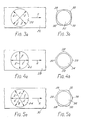
- FIG. 9 there is shown a punch 110 and die 111 forming part of a blanking apparatus.
- the punch 110 and die 111 are shown cutting a blank 112 from metal sheet 113.
- the die 111 which is of conventional design, has a generally annular shape.
- the outer surface of die 111 includes an annular face 114, a cylindrical part 115 and a collar 116, which serves to-locate the die 111 in the blanking apparatus.
- the inner surface of die 111 is of stepped cylindrical configuration and comprises a land part 117 and a recessed part 118.
- the annular face 114 and the land part 117 meet at a circular cutting edge.
- the punch 110 has a generally cylindrical shape and its surface comprises a flat upper face 120 joined to a ram 121, a cylindrical part 122 and a lower face 123.
- the cylindrical part 122 has a diameter D and is complimentary to the land part 117 of die 111.
- the cylindrical part 122 and lower face 123 meet at the cutting edge.
- Each lobe-forming section 124 is constructed by forming a recess in the cutting edge. Each recess extends circumferentially around the cutting edge through an angle slightly less than 90° and the lobe-forming sections are spaced from each other by portions of the cutting edge in which no recess is formed. As shown in Figure 11, each recess has a stepped configuration. Each recess has a constant width z. However, as shown by the graph in Fire 12, the depth y of the recess varies. More specifically, each recess has two straight portions joined by a radiused portion.
- each lobe-forming section 124 the area in cross-section which is absent from the cutting edge of the punch 110 by virtue of the recess increases progressively from the ends of the lobe-forming section towards the middle thereof.
- Figure 9 shows a blank 112 being cut from metal sheet 113 using the punch 110 and die 111.
- the punch 110 moves downwardly, in each lobe-forming section, the lower surface 123 of the punch 110 engages the metal sheet 1 13 before the metal sheet 113 is engaged by the cutting edge of the punch 110. Consequently, the recesses of the four lobe-forming sections 124 cause four lobes 126 to be formed.
- Each of the lobes 126 is bent upwardly from the general plane of the blank 112.
- FIG. 13 to 15 An example of a blank 112 is shown in Figures 13 to 15. As may be observed, both in plan view and in end view, the blank 112 has a constant diameter D which is equal to the diameter of the cylindrical part 122 of punch 110. As shown in Figure 15, when the blank 112 is flattened out, its diameter varies between a minimum value D and a maximum D + 2 (x ⁇ z), where x is given by ⁇ (y2 + z2) .
- the punch 110 and die 111 are suitable for use with metal sheet which has a tendency to produce four ears and four valleys in a workpeice during forming operations subsequent to blanking.
- the punch 110 is oriented relative to the metal sheet so that the four lobes are formed at positions where valleys would otherwise be formed.
- the maximum depth of the recess in each lobe-forming section should be chosen so as to cancel the valleys as exactly as possible. For a particular application, the depth of the recess will depend upon the properties of the metal sheet and the nature of the forming operations to which the blanks are subjected.
- a punch generally similar to punch 110 but in which the number of lobe-forming sections is equal to the number of valleys that would otherwise be produced.
- each recess has a stepped configuration. However, different shapes may be used.
- each recess may be formed with a plane which is oriented at 10° to the lower face of the punch.
- the punch and die which have been described with reference to Figures 9 to 12 are suitable for cutting blanks which are subsequently subjected to a variety of forming operations.
- Such forming operations may include drawing, redrawing, wall ironing and pressing.
- a blank cut with the punch and die of Figures 9 to 12 may be formed into a can body by a drawing operation followed by one or more redrawing operations.
- a blank may be formed into a can body by a drawing operation, a redrawing operation and a wall ironing operation.
- a blank may be formed into a can cover by a drawing operation followed by two redrawing operations.
- Conventional apparatus may be used for performing the drawing, redrawing and wall ironing operations.
- a punch and die embodying the present invention may form part of an apparatus which is capable of performing operations subsequent to blanking during a single stroke of the apparatus.
- a punch and die embodying the present invention may form part of an apparatus which performs a drawing operation, a redrawing operation and a wall ironing operation following a blanking operation during a single stroke of the apparatus.
- the punch is provided with lobe-forming sections in the manner described above but the remaining parts of the apparatus have a conventional design.
- compensation may be provided by forming a blank with lobes of unequal size.
- the punch 110 shown in Figures 9 to 11 may be used to produce such a blank by modifying the depths of the recesses in the lobe-forming sections.
- the nature of the anisotropy can be such that a workpiece formed from a circular blank has large valleys which would benefit from compensation and small valleys for which compensation is not necessary.
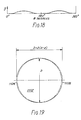
- a punch 1110 which is capable of producing a blank with two such lobes will now be described with reference to Figures 16 to 18 and a blank 1112 produced with the punch 1110 is shown in Figure 19.
- Figures 16 to 19 are generally similar to Figures 10, 11, 12 and 15 and like parts and features have been denoted by the same reference numerals preceded by the number "1".
- the punch 1110 has two diametrically opposite lobe-forming sections 1124.
- the variation of the depth of the recesses in the lobe-forming sections is shown in Figure 18.
- FIG 19 there is shown a blank 1112 produced by the punch 1110 and this blank has two diametrically opposite lobes 1126.
- metal strip or sheet should be interpreted to include strip or sheet material formed by laminating metal and plastics layers.
Priority Applications (1)
| Application Number | Priority Date | Filing Date | Title |
|---|---|---|---|
| AT90306704T ATE94437T1 (de) | 1989-07-26 | 1990-06-20 | Vorrichtung und verfahren zum ausstanzen einer blechplatine. |
Applications Claiming Priority (2)
| Application Number | Priority Date | Filing Date | Title |
|---|---|---|---|
| GB8917049 | 1989-07-26 | ||
| GB8917049A GB8917049D0 (en) | 1989-07-26 | 1989-07-26 | An apparatus for,and a method of,cutting a blank |
Publications (2)
| Publication Number | Publication Date |
|---|---|
| EP0410573A1 true EP0410573A1 (de) | 1991-01-30 |
| EP0410573B1 EP0410573B1 (de) | 1993-09-15 |
Family
ID=10660631
Family Applications (1)
| Application Number | Title | Priority Date | Filing Date |
|---|---|---|---|
| EP19900306704 Expired - Lifetime EP0410573B1 (de) | 1989-07-26 | 1990-06-20 | Vorrichtung und Verfahren zum Ausstanzen einer Blechplatine |
Country Status (19)
| Country | Link |
|---|---|
| US (1) | US5052207A (de) |
| EP (1) | EP0410573B1 (de) |
| JP (1) | JPH0357516A (de) |
| KR (1) | KR910002570A (de) |
| CN (1) | CN1031982C (de) |
| AT (1) | ATE94437T1 (de) |
| AU (1) | AU627911B2 (de) |
| BR (1) | BR9003609A (de) |
| CA (1) | CA2020483A1 (de) |
| DE (1) | DE69003324T2 (de) |
| FI (1) | FI903709A0 (de) |
| GB (2) | GB8917049D0 (de) |
| HK (1) | HK89293A (de) |
| IE (1) | IE65464B1 (de) |
| NO (1) | NO903308L (de) |
| NZ (1) | NZ234224A (de) |
| PT (1) | PT94815A (de) |
| SG (1) | SG62993G (de) |
| ZA (1) | ZA905272B (de) |
Cited By (4)
| Publication number | Priority date | Publication date | Assignee | Title |
|---|---|---|---|---|
| RU176136U1 (ru) * | 2017-04-26 | 2018-01-09 | Общество с ограниченной ответственностью "Информационные технологии" (ООО "ИнфоТех") | Штамп для вырубки крепежного элемента из колпака и основания электромагнитного реле |
| RU176665U1 (ru) * | 2017-04-26 | 2018-01-25 | Общество с ограниченной ответственностью "Информационные технологии" (ООО "ИнфоТех") | Штамп для вырубки лепестков из основания электромагнитного реле |
| RU176666U1 (ru) * | 2017-04-26 | 2018-01-25 | Общество с ограниченной ответственностью "Информационные технологии" (ООО "ИнфоТех") | Штамп для разрушения катушки электромагнитного реле |
| RU182945U1 (ru) * | 2017-04-26 | 2018-09-06 | Общество с ограниченной ответственностью "Информационные технологии" (ООО "ИнфоТех") | Штамп для вырубки крепежного узла из колпака электромагнитного реле |
Families Citing this family (20)
| Publication number | Priority date | Publication date | Assignee | Title |
|---|---|---|---|---|
| GB9119418D0 (en) * | 1991-09-11 | 1991-10-23 | Decorpart Ltd | Apparatus and methods for press forming of articles |
| US5950858A (en) * | 1993-02-18 | 1999-09-14 | Sergeant; David Robert | Container end closure |
| US5645189A (en) * | 1994-11-21 | 1997-07-08 | Metal Container Corporation | Container end having annular panel with non-uniform radius of curvature |
| US5730038A (en) * | 1995-01-25 | 1998-03-24 | Acco Usa, Inc. | Configuration for paper punch pin |
| US5823041A (en) * | 1997-06-06 | 1998-10-20 | Can Industry Products, Inc. | Method and apparatus for making a non-cylindrical can body |
| JP3942256B2 (ja) * | 1998-01-23 | 2007-07-11 | Ntn株式会社 | 軸受外輪及びその製造方法、並びにクラッチレリーズ軸受 |
| JP2002196179A (ja) * | 2000-10-17 | 2002-07-10 | Ngk Insulators Ltd | ファイバアレイ及びその製造方法並びにファイバアレイを用いた光デバイス |
| CN1298454C (zh) * | 2003-12-01 | 2007-02-07 | 中国重型汽车集团有限公司 | 一种加工盲孔的工艺方法 |
| JP2009037980A (ja) * | 2007-08-03 | 2009-02-19 | Panasonic Corp | 電池缶および金属缶用ブランクとこれを用いた電池缶および金属缶の製造方法 |
| JP5792751B2 (ja) * | 2010-03-10 | 2015-10-14 | ストール マシーナリ カンパニー, エルエルシーStolle Machinery Company, LLC | ツーリングアセンブリ、ツーリングアセンブリ用打抜き工具、及び関連方法 |
| KR101310240B1 (ko) * | 2011-03-10 | 2013-09-23 | 주식회사 알란텀 | 고표면적을 가지는 다공성 금속폼 콘 어셈블리의 제조방법 |
| CN102248770A (zh) * | 2011-05-30 | 2011-11-23 | 上海九星印刷包装有限公司 | 一种印刷机用印刷版面局部控制油墨的方法及其装置 |
| US8904911B2 (en) * | 2011-12-09 | 2014-12-09 | Textron Innovations Inc. | Sleeve for a punch assembly |
| DE102011121904A1 (de) * | 2011-12-21 | 2013-06-27 | Volkswagen Aktiengesellschaft | Verfahren zur scherenden Bearbeitung von Blechen mit einer anschließenden Umformung sowie ein hierzu bestimmtes Schneidwerkzeug |
| FR3016538B1 (fr) * | 2014-01-20 | 2016-07-15 | Constellium France | Procede de fabrication d'une boite-boisson, bouteille metallique ou boitier d'aerosol en alliage d'aluminium |
| KR101999459B1 (ko) * | 2014-12-10 | 2019-07-11 | 닛폰세이테츠 가부시키가이샤 | 블랭크, 성형품, 금형 및 블랭크의 제조 방법 |
| CN106393276A (zh) * | 2016-10-19 | 2017-02-15 | 东莞市睿奇五金制品有限公司 | 一种装饰条上下半切工艺及模具 |
| CN107755515A (zh) * | 2017-10-23 | 2018-03-06 | 无锡吉兴汽车声学部件科技有限公司 | 一种乘用车冲切模具刀口结构 |
| US20220274152A1 (en) * | 2019-07-30 | 2022-09-01 | Rockhouse International Pty Ltd | Punch and Die Assembly |
| US20220115849A1 (en) * | 2020-10-08 | 2022-04-14 | Milbank Manufacturing Co. | Punch set for electrical box |
Citations (10)
| Publication number | Priority date | Publication date | Assignee | Title |
|---|---|---|---|---|
| DE402120C (de) * | 1923-01-20 | 1924-09-15 | Walter Brewitt Dipl Ing | Drehbarer Stanzstempel mit unterbrochenen Schneidzaehnen |
| GB963856A (en) * | 1962-03-26 | 1964-07-15 | Merrill David Martin | Device and method for forming holes in blanks |
| DE1928697A1 (de) * | 1969-06-06 | 1970-12-10 | Leitz Fa Louis | Locherstempel fuer Brieflocher |
| DE1761581A1 (de) * | 1968-06-11 | 1971-07-08 | Leitz Louis | Locher fuer Schriftgut |
| DE1602491A1 (de) * | 1967-06-16 | 1971-07-08 | Fischer Brodbeck Gmbh | Stanzstempel,insbesondere zur Herstellung von Lochungen |
| DE2144524A1 (de) * | 1971-09-06 | 1973-03-15 | Novopress Gmbh | Schnittwerkzeuge |
| US3996832A (en) * | 1975-04-10 | 1976-12-14 | Standard Oil Company (Indiana) | Punch for producing holes in foamed thermoplastic containers |
| FR2418703A1 (fr) * | 1978-03-03 | 1979-09-28 | Mitsuhashi Yoshio | Poincon pour perforateurs manuels a papier ou matieres similaires |
| US4277891A (en) * | 1980-06-13 | 1981-07-14 | American Optical Corporation | Lens tape cutter |
| US4362078A (en) * | 1980-03-25 | 1982-12-07 | Akzona Incorporated | Method of blanking |
Family Cites Families (7)
| Publication number | Priority date | Publication date | Assignee | Title |
|---|---|---|---|---|
| US3060992A (en) * | 1960-01-11 | 1962-10-30 | Hopp | Means and method for forming non-planar articles |
| BE758810A (fr) * | 1969-11-15 | 1971-04-16 | Kondo Kazuyoshi | Procede de cisaillement de precision |
| US3656394A (en) * | 1970-08-10 | 1972-04-18 | Tally Corp | Punch configuration |
| JPS5758927A (en) * | 1980-09-25 | 1982-04-09 | Toyota Motor Corp | Precision blanking die |
| JPS5897433A (ja) * | 1981-12-03 | 1983-06-09 | Toshiba Corp | 不均衝形状の抜型 |
| JPS59118232A (ja) * | 1982-12-24 | 1984-07-07 | Nissan Motor Co Ltd | バ−リングポンチ |
| JPS61172629A (ja) * | 1985-01-26 | 1986-08-04 | Doi Kogyo Kk | 打抜加工用工具 |
-
1989
- 1989-07-26 GB GB8917049A patent/GB8917049D0/en active Pending
-
1990
- 1990-06-20 GB GB9013777A patent/GB2234197B/en not_active Expired - Fee Related
- 1990-06-20 DE DE1990603324 patent/DE69003324T2/de not_active Expired - Fee Related
- 1990-06-20 AT AT90306704T patent/ATE94437T1/de not_active IP Right Cessation
- 1990-06-20 EP EP19900306704 patent/EP0410573B1/de not_active Expired - Lifetime
- 1990-06-25 NZ NZ234224A patent/NZ234224A/en unknown
- 1990-06-26 US US07/544,617 patent/US5052207A/en not_active Expired - Fee Related
- 1990-07-04 KR KR1019900010069A patent/KR910002570A/ko not_active Application Discontinuation
- 1990-07-05 ZA ZA905272A patent/ZA905272B/xx unknown
- 1990-07-05 CA CA 2020483 patent/CA2020483A1/en not_active Abandoned
- 1990-07-23 CN CN90104816A patent/CN1031982C/zh not_active Expired - Fee Related
- 1990-07-24 FI FI903709A patent/FI903709A0/fi not_active IP Right Cessation
- 1990-07-25 BR BR9003609A patent/BR9003609A/pt not_active Application Discontinuation
- 1990-07-25 PT PT94815A patent/PT94815A/pt not_active Application Discontinuation
- 1990-07-25 NO NO90903308A patent/NO903308L/no unknown
- 1990-07-25 AU AU59764/90A patent/AU627911B2/en not_active Ceased
- 1990-07-25 IE IE269790A patent/IE65464B1/en not_active IP Right Cessation
- 1990-07-26 JP JP2196426A patent/JPH0357516A/ja active Pending
-
1993
- 1993-05-12 SG SG62993A patent/SG62993G/en unknown
- 1993-08-26 HK HK89293A patent/HK89293A/xx not_active IP Right Cessation
Patent Citations (10)
| Publication number | Priority date | Publication date | Assignee | Title |
|---|---|---|---|---|
| DE402120C (de) * | 1923-01-20 | 1924-09-15 | Walter Brewitt Dipl Ing | Drehbarer Stanzstempel mit unterbrochenen Schneidzaehnen |
| GB963856A (en) * | 1962-03-26 | 1964-07-15 | Merrill David Martin | Device and method for forming holes in blanks |
| DE1602491A1 (de) * | 1967-06-16 | 1971-07-08 | Fischer Brodbeck Gmbh | Stanzstempel,insbesondere zur Herstellung von Lochungen |
| DE1761581A1 (de) * | 1968-06-11 | 1971-07-08 | Leitz Louis | Locher fuer Schriftgut |
| DE1928697A1 (de) * | 1969-06-06 | 1970-12-10 | Leitz Fa Louis | Locherstempel fuer Brieflocher |
| DE2144524A1 (de) * | 1971-09-06 | 1973-03-15 | Novopress Gmbh | Schnittwerkzeuge |
| US3996832A (en) * | 1975-04-10 | 1976-12-14 | Standard Oil Company (Indiana) | Punch for producing holes in foamed thermoplastic containers |
| FR2418703A1 (fr) * | 1978-03-03 | 1979-09-28 | Mitsuhashi Yoshio | Poincon pour perforateurs manuels a papier ou matieres similaires |
| US4362078A (en) * | 1980-03-25 | 1982-12-07 | Akzona Incorporated | Method of blanking |
| US4277891A (en) * | 1980-06-13 | 1981-07-14 | American Optical Corporation | Lens tape cutter |
Non-Patent Citations (3)
| Title |
|---|
| PATENT ABSTRACTS OF JAPAN, vol. 10, no. 381 (M-547)[2438], 19th December 1986; & JP-A-61 172 629 (DOI KOGYO) 04-08-1986 * |
| PATENT ABSTRACTS OF JAPAN, vol. 7, no. 197 (M-239)[1342], 27th August 1983; & JP-A-58 097 433 (TOKYO SHIBAURA) 09-06-1983 * |
| PATENT ABSTRACTS OF JAPAN, vol. 8, no. 238 (M-335)[1675], 31st October 1984; & JP-A-59 118 232 (NISSAN JIDOSHA) 07-07-1984 * |
Cited By (4)
| Publication number | Priority date | Publication date | Assignee | Title |
|---|---|---|---|---|
| RU176136U1 (ru) * | 2017-04-26 | 2018-01-09 | Общество с ограниченной ответственностью "Информационные технологии" (ООО "ИнфоТех") | Штамп для вырубки крепежного элемента из колпака и основания электромагнитного реле |
| RU176665U1 (ru) * | 2017-04-26 | 2018-01-25 | Общество с ограниченной ответственностью "Информационные технологии" (ООО "ИнфоТех") | Штамп для вырубки лепестков из основания электромагнитного реле |
| RU176666U1 (ru) * | 2017-04-26 | 2018-01-25 | Общество с ограниченной ответственностью "Информационные технологии" (ООО "ИнфоТех") | Штамп для разрушения катушки электромагнитного реле |
| RU182945U1 (ru) * | 2017-04-26 | 2018-09-06 | Общество с ограниченной ответственностью "Информационные технологии" (ООО "ИнфоТех") | Штамп для вырубки крепежного узла из колпака электромагнитного реле |
Also Published As
| Publication number | Publication date |
|---|---|
| DE69003324D1 (de) | 1993-10-21 |
| ATE94437T1 (de) | 1993-10-15 |
| GB9013777D0 (en) | 1990-08-08 |
| SG62993G (en) | 1993-08-06 |
| EP0410573B1 (de) | 1993-09-15 |
| CN1031982C (zh) | 1996-06-12 |
| IE902697A1 (en) | 1991-02-27 |
| CN1048993A (zh) | 1991-02-06 |
| JPH0357516A (ja) | 1991-03-12 |
| KR910002570A (ko) | 1991-02-25 |
| US5052207A (en) | 1991-10-01 |
| AU5976490A (en) | 1991-01-31 |
| IE65464B1 (en) | 1995-11-01 |
| DE69003324T2 (de) | 1994-03-17 |
| PT94815A (pt) | 1992-06-30 |
| NZ234224A (en) | 1992-06-25 |
| FI903709A0 (fi) | 1990-07-24 |
| GB2234197B (en) | 1993-04-21 |
| BR9003609A (pt) | 1991-08-27 |
| ZA905272B (en) | 1991-04-24 |
| GB2234197A (en) | 1991-01-30 |
| CA2020483A1 (en) | 1991-01-27 |
| NO903308L (no) | 1991-01-28 |
| HK89293A (en) | 1993-09-03 |
| NO903308D0 (no) | 1990-07-25 |
| AU627911B2 (en) | 1992-09-03 |
| GB8917049D0 (en) | 1989-09-13 |
Similar Documents
| Publication | Publication Date | Title |
|---|---|---|
| EP0410573B1 (de) | Vorrichtung und Verfahren zum Ausstanzen einer Blechplatine | |
| US20080229802A1 (en) | Method of Forming a Metal Sheet Blank | |
| US4254540A (en) | Stamped bevel gear | |
| US5309704A (en) | Method of producing chain links and chain links produced therefrom | |
| US20130276603A1 (en) | Punch of punching press, nibbler assembly, and method of forming elongated hole in sheet material | |
| US5604044A (en) | Blanks for sheet material forming process | |
| US5544477A (en) | Method of producing chain links for fine jewelry rope chains | |
| US4863333A (en) | Apparatus for forming cans | |
| JPH01140992A (ja) | スカラップ状切刃を有するナイフの製作方法 | |
| JP3030936B2 (ja) | 絞り加工方法 | |
| JP3413140B2 (ja) | プレス機による追い抜き加工方法 | |
| US6269672B1 (en) | Indentations to control metal curling | |
| JPS59174233A (ja) | 仕上げ抜き方法及びその装置 | |
| EP0295910B1 (de) | Kompakte Schneidmesser-Baugruppe | |
| GB2102707A (en) | Manufacture of anti-slip decking | |
| CN116995512B (zh) | 一种模内铆接夹线端子的冲压工艺 | |
| US5823041A (en) | Method and apparatus for making a non-cylindrical can body | |
| RU1819711C (ru) | Штамп последовательного действи дл получени заготовок петель из полосы | |
| GB1587006A (en) | Method of forming an article having an opening therein | |
| JPH04237523A (ja) | 薄板部材の曲げ加工方法およびその装置 | |
| JP2512923B2 (ja) | プレス品の抜孔部曲げ加工方法 | |
| JPH07148532A (ja) | カーリング加工方法 | |
| JPS63165026A (ja) | プレス型 | |
| JP2826875B2 (ja) | コイニング加工方法 | |
| SU994086A1 (ru) | Способ получени отверстий в листовых заготовках |
Legal Events
| Date | Code | Title | Description |
|---|---|---|---|
| PUAI | Public reference made under article 153(3) epc to a published international application that has entered the european phase |
Free format text: ORIGINAL CODE: 0009012 |
|
| 17P | Request for examination filed |
Effective date: 19900626 |
|
| AK | Designated contracting states |
Kind code of ref document: A1 Designated state(s): AT BE CH DE DK ES FR GB GR IT LI LU NL SE |
|
| 17Q | First examination report despatched |
Effective date: 19920327 |
|
| RAP1 | Party data changed (applicant data changed or rights of an application transferred) |
Owner name: CARNAUDMETALBOX PLC |
|
| GRAA | (expected) grant |
Free format text: ORIGINAL CODE: 0009210 |
|
| AK | Designated contracting states |
Kind code of ref document: B1 Designated state(s): AT BE CH DE DK ES FR GB GR IT LI LU NL SE |
|
| PG25 | Lapsed in a contracting state [announced via postgrant information from national office to epo] |
Ref country code: IT Free format text: LAPSE BECAUSE OF FAILURE TO SUBMIT A TRANSLATION OF THE DESCRIPTION OR TO PAY THE FEE WITHIN THE PRESCRIBED TIME-LIMIT;WARNING: LAPSES OF ITALIAN PATENTS WITH EFFECTIVE DATE BEFORE 2007 MAY HAVE OCCURRED AT ANY TIME BEFORE 2007. THE CORRECT EFFECTIVE DATE MAY BE DIFFERENT FROM THE ONE RECORDED. Effective date: 19930915 Ref country code: ES Free format text: THE PATENT HAS BEEN ANNULLED BY A DECISION OF A NATIONAL AUTHORITY Effective date: 19930915 Ref country code: NL Effective date: 19930915 Ref country code: LI Effective date: 19930915 Ref country code: CH Effective date: 19930915 Ref country code: DK Effective date: 19930915 Ref country code: AT Effective date: 19930915 Ref country code: BE Effective date: 19930915 Ref country code: GR Free format text: LAPSE BECAUSE OF FAILURE TO SUBMIT A TRANSLATION OF THE DESCRIPTION OR TO PAY THE FEE WITHIN THE PRESCRIBED TIME-LIMIT Effective date: 19930915 Ref country code: SE Effective date: 19930915 |
|
| REF | Corresponds to: |
Ref document number: 94437 Country of ref document: AT Date of ref document: 19931015 Kind code of ref document: T |
|
| REF | Corresponds to: |
Ref document number: 69003324 Country of ref document: DE Date of ref document: 19931021 |
|
| RBV | Designated contracting states (corrected) |
Designated state(s): AT BE CH DE DK ES FR GR IT LI LU NL SE |
|
| REG | Reference to a national code |
Ref country code: CH Ref legal event code: PL |
|
| ET | Fr: translation filed | ||
| NLV1 | Nl: lapsed or annulled due to failure to fulfill the requirements of art. 29p and 29m of the patents act | ||
| PG25 | Lapsed in a contracting state [announced via postgrant information from national office to epo] |
Ref country code: LU Free format text: LAPSE BECAUSE OF NON-PAYMENT OF DUE FEES Effective date: 19940630 |
|
| PLBE | No opposition filed within time limit |
Free format text: ORIGINAL CODE: 0009261 |
|
| STAA | Information on the status of an ep patent application or granted ep patent |
Free format text: STATUS: NO OPPOSITION FILED WITHIN TIME LIMIT |
|
| 26N | No opposition filed | ||
| PGFP | Annual fee paid to national office [announced via postgrant information from national office to epo] |
Ref country code: FR Payment date: 19980508 Year of fee payment: 9 |
|
| PGFP | Annual fee paid to national office [announced via postgrant information from national office to epo] |
Ref country code: DE Payment date: 19980528 Year of fee payment: 9 |
|
| PG25 | Lapsed in a contracting state [announced via postgrant information from national office to epo] |
Ref country code: FR Free format text: THE PATENT HAS BEEN ANNULLED BY A DECISION OF A NATIONAL AUTHORITY Effective date: 19990630 |
|
| PG25 | Lapsed in a contracting state [announced via postgrant information from national office to epo] |
Ref country code: DE Free format text: LAPSE BECAUSE OF NON-PAYMENT OF DUE FEES Effective date: 20000503 |
|
| REG | Reference to a national code |
Ref country code: FR Ref legal event code: ST |