EP0405090B1 - Grasbehälter für Rasenmäher - Google Patents
Grasbehälter für Rasenmäher Download PDFInfo
- Publication number
- EP0405090B1 EP0405090B1 EP90107930A EP90107930A EP0405090B1 EP 0405090 B1 EP0405090 B1 EP 0405090B1 EP 90107930 A EP90107930 A EP 90107930A EP 90107930 A EP90107930 A EP 90107930A EP 0405090 B1 EP0405090 B1 EP 0405090B1
- Authority
- EP
- European Patent Office
- Prior art keywords
- mowed grass
- shielding plate
- mowed
- containing unit
- upper cover
- Prior art date
- Legal status (The legal status is an assumption and is not a legal conclusion. Google has not performed a legal analysis and makes no representation as to the accuracy of the status listed.)
- Expired - Lifetime
Links
- 244000025254 Cannabis sativa Species 0.000 title claims abstract description 142
- 230000007246 mechanism Effects 0.000 claims abstract description 3
- XEEYBQQBJWHFJM-UHFFFAOYSA-N Iron Chemical compound [Fe] XEEYBQQBJWHFJM-UHFFFAOYSA-N 0.000 description 8
- 238000007599 discharging Methods 0.000 description 6
- 239000000428 dust Substances 0.000 description 5
- 229910052742 iron Inorganic materials 0.000 description 4
- 230000008878 coupling Effects 0.000 description 3
- 238000010168 coupling process Methods 0.000 description 3
- 238000005859 coupling reaction Methods 0.000 description 3
- 239000000463 material Substances 0.000 description 3
- 239000004744 fabric Substances 0.000 description 2
- 238000005452 bending Methods 0.000 description 1
- 230000005540 biological transmission Effects 0.000 description 1
- 238000004140 cleaning Methods 0.000 description 1
- 238000010276 construction Methods 0.000 description 1
- 230000001419 dependent effect Effects 0.000 description 1
- 230000005484 gravity Effects 0.000 description 1
- 239000002184 metal Substances 0.000 description 1
- 229910052751 metal Inorganic materials 0.000 description 1
- 230000004048 modification Effects 0.000 description 1
- 238000012986 modification Methods 0.000 description 1
- 230000002093 peripheral effect Effects 0.000 description 1
- 238000011084 recovery Methods 0.000 description 1
- 230000007480 spreading Effects 0.000 description 1
- 125000000391 vinyl group Chemical group [H]C([*])=C([H])[H] 0.000 description 1
- 229920002554 vinyl polymer Polymers 0.000 description 1
Images


Classifications
-
- A—HUMAN NECESSITIES
- A01—AGRICULTURE; FORESTRY; ANIMAL HUSBANDRY; HUNTING; TRAPPING; FISHING
- A01D—HARVESTING; MOWING
- A01D43/00—Mowers combined with apparatus performing additional operations while mowing
- A01D43/06—Mowers combined with apparatus performing additional operations while mowing with means for collecting, gathering or loading mown material
- A01D43/063—Mowers combined with apparatus performing additional operations while mowing with means for collecting, gathering or loading mown material in or into a container carried by the mower; Containers therefor
- A01D43/0635—Mowers combined with apparatus performing additional operations while mowing with means for collecting, gathering or loading mown material in or into a container carried by the mower; Containers therefor with emptying means
-
- A—HUMAN NECESSITIES
- A01—AGRICULTURE; FORESTRY; ANIMAL HUSBANDRY; HUNTING; TRAPPING; FISHING
- A01D—HARVESTING; MOWING
- A01D2101/00—Lawn-mowers
-
- A—HUMAN NECESSITIES
- A01—AGRICULTURE; FORESTRY; ANIMAL HUSBANDRY; HUNTING; TRAPPING; FISHING
- A01D—HARVESTING; MOWING
- A01D34/00—Mowers; Mowing apparatus of harvesters
- A01D34/01—Mowers; Mowing apparatus of harvesters characterised by features relating to the type of cutting apparatus
- A01D34/412—Mowers; Mowing apparatus of harvesters characterised by features relating to the type of cutting apparatus having rotating cutters
- A01D34/63—Mowers; Mowing apparatus of harvesters characterised by features relating to the type of cutting apparatus having rotating cutters having cutters rotating about a vertical axis
Definitions
- This invention relates to a mowed grass container for a mowing machine such as a garden tractor, a lawn tractor, a ride mower, etc. and, more particularly, to a mowed grass container for a riding type mowing machine in which the mowed grass container can be opened and closed in a carried state and a mowed grass containing unit is detachably attached to a shielding plate through a pivot, according to the pre-characterizing part of claim 1.
- a mowed grass container is known from AU-B-10154/88.
- a columnar piece is vertically fixed to the rear portion of a lawn tractor body, the center of a lateral piece of a plainly U-shaped frame is fixed to the upper end of the columnar piece, and the rear portion is opened to form a mowed grass containing bag supporting frame.
- the mowed grass containing bag is so constructed as to fix the upper edge of a cloth bag body to a rectangular frame, and to place the rectangular frame in the U-shaped piece.
- Grips are pivotally secured to the centers of the right and left sides of the rectangular frame, the grips are tilted forwardly when the rectangular frame of the mowed grass containing bag is placed on the upper face of the U-shaped piece, further tilted down to the front face of the columnar piece to be engaged, and a rotatable cover is coated on the upper face of the columnar piece.
- an object of this invention is to provide a mowed grass container for a mowing machine such that the mowed grass disposal operation can be easily, rapidly and securely conducted while the driver is riding on the riding type mowing machine body, wherein furthermore functions of attaching and detaching the mowed grass containing bag are provided.
- an upper cover may be fixed to a bow-shaped frame pivotally secured and rotatably about an axis defined by the extremes of the bow-shape.
- said upper cover is composed of a bellows.
- a connector is provided at the upper frame of said mowed grass containing unit, and a holding member pivotally secured to an upper cover fame is engageable with said connector.
- said holding member is a handle for discharging mowed grass in said mowed grass containing unit and is disposed at a distance to be contacted with a drivers hand.
- the mowed grass container for a mowing machine when the mowed grass mowed by the mower is recovered by the mowed grass container, the upper face of the mowed grass containing unit is opened, and the open portion of the shielding plate side is press-bonded to the shielding plate. Accordingly, the mowed grass can be recovered to the mowed grass containing unit.
- the open portion of the mowed grass containing unit to the shielding plate side is naturally press-bonded to the shielding plate by the own weight of the mowed grass containing unit at the positional relationship of the containing unit to the shielding plate, and the press-bonded state is not accidentally opened even by the vibration of the machine body.
- the handle is provided at the pivot, the handle is held to direct the open face of the containing unit upward, thereby carrying the containing unit to an arbitrary position to dispose the mowed grass without accidentally leaking the mowed grass.
- the mowed grass containing unit is so constructed as to rotate at the pivot as a rotating center to direct the open portion of the containing unit at the shielding plate side downwardly, when the holding piece is provided at the containing unit to hold the holding piece to rotate the piece, the containing unit is released in the shielding state by the shielding plate to direct the open portion of the shielding plate side downwardly.
- the mowed grass can be disposed, and when the holding piece is rotated reversibly, the open portion of the containing unit at the shielding plate side is again shielded by the shielding plate so that the upper face becomes open, thereby continuously recovering the mowed grass.
- the upper cover is opened at the face of the shielding plate side and the lower face, but when the mowed grass is recovered by the mowed grass containing unit, the open face of the shielding plate side is brought into pressure contact with the shielding plate, and is hence fed to the container unit aligned under the open portion of the lower face.
- the upper cover is according to the invention constructed to be longitudinally foldable i.e. along a direction substantially in alignment with the longitudinal axis of the tractor, it can be folded arbitrarily in both forward and reverse directions to open the upper face of the containing unit, thereby easily attaching or detaching the lower mowed grass containing unit.
- the upper cover Since the upper cover is fixed to the bow-shaped frame rotatable about an axis defined by its extremities, the upper cover can be easily opened or closed by the longitudinal rotating operation of the bow-shaped frame. In this case, since the bow-shaped frame can pivotally secure the handle, the upper cover can be opened or closed through the handle operation.
- the upper cover is formed of the bellows, the upper cover can be easily opened or closed, and since the upper cover is not of hard box, the upper cover is not opened to the vicinity of the driver's seat of the machine body over the shielding plate at the time of opening or closing the upper cover, but the upper cover can be always opened or closed outside the shielding plate.
- the connector is provided at the upper frame of the mowed grass containing unit and the holding member pivotally secured to the upper cover frame is connected to the connector, the member is connected to the connector to thereby rotate the containing unit to direct the open portion of the containing unit at the shielding plate side by rotating the member.
- the mowed grass recovered in the containing unit can be easily disposed, and when the member is reversibly rotated, the vacant containing unit can be returned to the original position to advance the next mowed grass recovering work.
- the holding member is of the handle for discharging the mowed grass in the containing unit and disposed at a distance in contact with the driver's hand, the mowed grass in the containing unit can be discharged by holding the handle while the driver is sitting on the driver's seat and can return the containing unit after the mowed grass is completely discharged, thereby improving the operability.
- reference numeral 1 denotes a lawn tractor.
- a coupling hitch 3 is provided at the rear side of a frame 2 of the lawn tractor 1.
- a mower 8 is vertically movably coupled to the frame between front wheels 4, 4 and rear wheels 5, 5 through hanging links 6, 6 and 7, 7 and is driven by a belt transmission mechanism 9.
- a mowed grass discharging tube 11 is coupled to the right side discharge port (not shown) of a mower deck 10 of the mower 8, and its rear end is so attached as to recover the grass mowed by a rotary mowing cutter in the mower deck 10 into a mowed grass container 12 coupled to the coupling hitch 3.
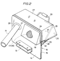
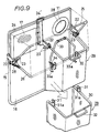
- the mowed grass container 12 is detachably coupled to the coupling hitch 3 through a mount 13, which is in turn fixed to the vicinity of the lower end of a shielding plate 16 provided in front of the mowed grass container 12 substantially at the center thereof.
- the shielding plate 16 is composed by fixing a rectangular frame 15 bent from a pipe material to the peripheral surface of a rectangular iron plate 14.
- the mowed grass discharge tube 11 which is coupled to the discharge port (not shown) of the mower deck 10 at its right side extends rearwardly along the outside of the right side rear wheel 5 and terminates at its rear portion at a cylinder mount 21 provided on the iron plate 14 and thus opens into the mowed grass container 12.
- Supporting arms 22, 22 protrude at the right and left sides of the longitudinal frame 15 adjacent from the lower sides of the dust discharger 18 and the cylinder mount 21 toward a rearward direction, as seen in Fig. 2. Further, the supporting arms 22, 22 protrude in a length x (Fig.
- the frames 24, 25 and 26 each are arranged such that they are approximately in form of an inverted "U".
- the bow-shaped frames 24, 25, 26 are respectively fixed to an upper end, intermediate portion and lower end of a cover 27 composed by spreading a cloth, vinyl sheet or bellows.
- the upper bow-shaped frame 24 is fixed to the shielding plate side (front edge) of the cover 27 to be contactable with the shielding plate 16.
- the lower bow-shaped frame 26 is fixed to the backside edge of the cover 27 to accurately hold same.
- the intermediate bow-shaped frame 25 is provided substantially at an intermediate portion between the upper bow-shaped frame 24 and the lower bow-shaped frame 26, and is so fixed to the cover 27 as to hold the cover 27 substantially in a square shape as seen from its side.
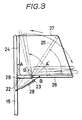
- the bow-shaped frames 24, 25, 26 are rotatable at approximately 90° rearward of the shielding plate 16 with the pivotal pins 23, 23 as rotating centers to open and close the cover 27 longitudinally. "Longitudinally" means that the cover 27 is openable and closeable along directions being substantially in alignment with the longitudinal axis of tractor 1.
- springs 28, 28 are interposed between the side face of the upper frame 24 and the side face of the lower frame 26 and the side face of the rectangular frame 15 of the shielding plate 16, respectively, and the springs 28, 28 bias to pivotally rotate the upper and lower frames 24 and 26 at the pivotal pins 23 as fulcra to the shielding plate 16 side and the rear horizontal position side, respectively.
- the springs 28, 28 are so provided at opposite sides as not to collide with each other.
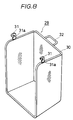
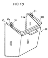
- Fig. 8 shows a mowed grass containing unit 29 which upper and front faces opened in a square shape as seen from its side. Three faces except a bottom plate are composed of meshes but are not limited to the particular example.
- a frame 30 formed by bending a pipe material is fixed to the open edge.
- hooks 31, 31, which oppositely protrude from frame 30 are movably in engagement with the pivotal pins 23, 23, wherein cutouts 31a, 31a are so cut out from the front positions of the hooks 31, 31 as to be insertable with or removable from the pivotal pins 23, 23 from an obliquely lower side.
- cutouts 31a, 31a are so cut out from the front positions of the hooks 31, 31 as to be insertable with or removable from the pivotal pins 23, 23 from an obliquely lower side.
- a holder piece 33b may be formed between the hooks 31 and 31.
- the mowed grass containing unit can be carried with the open side upward by means of its center of gravity when holding the holder piece 33b.
- the mowed grass in the mowed grass containing unit 29 can be carried to an arbitrary place without accidentally leaking the grass and then be disposed as shown in Fig. 12.
- Fig. 9 two mowed grass containing units 29 are respectively aligned at right and left sides, and covered at the tops with top covers.
- pivotal pins 23, 23 protrude from both side faces of a supporting arm 22 protruding at the center of the back face of the shielding plate 16 to pivotally secure the mowed grass containing units 29 and 29 at the right and left sides.
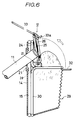
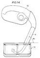
- a U-shaped connector 32 protrudes at the rear center of the frame 30 of the mowed grass containing unit 29 to engage bent portions 33a, 33a of both side lower ends of a handle 33 pivotally secured to the lower bow-shaped frame 26 of the cover 27.
- the handle 33 is always so rearwardly biased at its lower end by a spring 34 as to maintain a connecting state.
- the handle 33 is disposed at a position to be easily gripped by a drivers hand in the state that the driver sits on a driver's seat 35 and is formed so as to be simultaneously in engagement with the connectors 32, 32 of the mowed grass containing units 29, 29 aligned at the right and left sides of the back face of the shielding plate 16.
- the driver can grasp the handle 33 while sitting on the drivers seat and when he then pulls the handle, the mowed grass containing units 29, 29 can be rotated with the open portion of the front faces of the containing units 29, 29 directed downward as shown in Fig. 7. Therefore, the mowed grass in the mowed grass containing units 29, 29 is easily, rapidly and securely discharged.
- the handle 33 is rotated to the original position, the containing units 29, 92 are thus rotated back such that the open portions of the front faces thereof are brought into pressure contact with the back face of the shielding plate 16, thereby preparing next mowed grass recovery.
- Reference numeral 34' denotes a holder piece, which protrudes from the center of the upper bow-shaped frame 24 of the upper cover 27.
- the upper bow-shaped frame 24 is longitudinally rotated by holding the holder piece 34'.
- the upper cover 27 is opened by the rotation of the upper and lower bow-shaped frames 24, 26 longitudinally away from shielding plate 16 or the upper bow-shaped frame 24 is rotated towards the shielding plate 16 and the lower bow-shaped frame 26 is rotated to a horizontal position to be fixed by the springs 28, 28 to thereby close the upper faces of the mowed grass containing units 29, 29.
- the upper and lower bow-shaped frames 24, 26 are fixed to the shielding plate 16 side or horizontally in a superimposed state with the intermediate bow-shaped frame 25 by the springs 28, 28 to maintain the open state. This can be utilized to inspect the recovering state of the mowed grass in the mowed grass containing units 29, 29 or when cleaning the mowed grass containing units.
- the bent portions 33a, 33a of the lower end of the handle 33 can be disengaged from the connectors 32, 32, the handle 33 is then held by hand, and pulled. Then, the upper cover is moved to the shielding plate 16 side to open the upper faces of the containing units 29, 29.
- the grass mowed by the mowing machine is fed to the mowed grass containing unit of the mowed grass container through feeding means.
- the holding member being in engagement with the connector formed at the containing unit is rotated.
- the open portion of the mowed grass containing unit at the shielding plate side is rotated downwardly to discharge the mowed grass contained therein. If only the upper cover is opened and closed, the mowed grass containing state of the mowed grass containing unit can be inspected.
- the upper cover can also be opened to the shielding plate side to disconnect the mowed grass containing unit from the pivotal pin and to carry it to an arbitrary disposal place by holding it by hands thereby to dispose the mowed grass.
- the shielding plate side of the cover is brought into pressure contact with the shielding plate to be fixed there at the time of recovering the mowed grass. Accordingly, the mowed grass can be always fed under pressure into the lower mowed grass containing unit. Further, the lower mowed grass containing unit can be opened at its upper face and shielding plate side, and the open portion of the shielding plate side is blocked by the shielding plate at the time of recovering the mowed grass. Therefore, the mowed grass recovering operation can be easily performed without fail, and the mowed grass discharging operation can be smoothly conducted as described above.
- the upper cover can be used together with the mowing machine body or the rotation of the bow-shaped frames or further by the holding member to further improve the mowed grass discharging operation to shorten the time and improve the operability.
Landscapes
- Life Sciences & Earth Sciences (AREA)
- Environmental Sciences (AREA)
- Harvester Elements (AREA)
Claims (6)
- Grasbehälter für einen Rasenmäher, wobei der Rasenmäher (1) ein Mähwerk (8) aufweist, welches an einem Maschinenchassis mittels eines Hänge-Verbindungsmechanismus (6, 7) angeordnet ist, um von dem Mähwerk (8) gemähtes Gras in dem Grasbehälter (12) zu sammeln,
wobei der Grasbehälter (12) an dem Maschinenchassis angeordnet ist und eine Abschirmplatte (16), welche mit dem Maschinenchassis verbunden ist, eine obere Abdeckung (27), die so angeordnet ist, das sie mit einem Teil ihres Umfanges in paralleler Anlage entlang der Seitenfläche der Abschirmplatte (16) verläuft und eine darunterliegende Grasaufnahmeeinheit (29) aufweist, wobei die untere Grasaufnahmeeinheit (29) an der Seite, welche nach oben weist und an der Seite, welche der Abschirmplatte (16) zugewandt ist offen ist und weiterhin an der Abschirmplatte (16) mittels Schwenkzapfen (23) angebracht ist, welche an einer Stelle entfernt von der Abschirmplatte (16) vorgesehen sind, um um die Schwenkzapfen (23) drehbar zu sein, um die der Abschirmplatte (16) zugewandte Seite für eine nach unten erfolgende Entleerung von aufgesammteltem gemähtem Gras zu öffnen,
dadurch gekennzeichnet, daß
die obere Abdeckung (27) um eine einzige Achse derart faltbar ist, daß sie sowohl zu der Seite, welche der Abschirmplatte (16) zugewandt ist, als auch zu der Seite, welche nach unten in Richtung der nach oben weisenden Seite der unteren Grasaufnahmeeinheit (29) geöffnet werden kann, wobei die obere Abdeckung (27) in ihrem geschlossenem, ungefalteten Zustand mittels Federn (28) gehalten ist. - Der Grasbehälter nach Anspruch 1, wobei der Grasbehälter (12) abnehmbar an der Abschirmplatte (16) angebracht ist.
- Der Grasbehälter nach Anspruch 1 oder 2, wobei die obere Abdeckung (27) an bogenförmigen Rahmenteilen (24, 25, 26) befestigt ist, welche schwenkbeweglich für eine Drehung um die einzige Achse entweder in Richtung der Seite, welche zur Abschirmplatte (16) hinweist oder in Richtung der Seite, welche nach unten in Richtung der nach oben weisenden Seite der unteren Grasaufnahmeeinheit (29) weist festgelegt sind.
- Der Grasbehälter nach Anspruch 1, 2 oder 3, wobei die obere Abdeckung (27) aus einem Faltenbalg gebildet ist.
- Der Grasbehälter nach einem der Ansprüche 1 bis 4, wobei Betätigungsmittel (32) an einem oberen Rahmen (30) der Grasaufnahmeeinheit (29) vorgesehen sind und wobei ein Halteteil (33), das schwenkbeweglich an einem (26) der Rahmenteile (24, 25, 26) der oberen Abdeckung (27) angeordnet ist, mit der Betätigungsvorrichtung (32) derart in Eingriff bringbar ist, daß die Grasaufnahmeeinheit (29) um die Schwenkzapfen (23) gedreht werden kann, um die der Abschirmplatte (16) zugewandte Seite für eine nach unten gerichtete Entleerung von gesammelten gemähten Gras zu öffnen.
- Der Grasbehälter nach Anspruch 5, wobei das Halteteil (33) ein Handgriff ist, der so angeordnet ist, daß er zum Ergreifen durch die Hand eines Fahrers geeignet ist.
Applications Claiming Priority (4)
| Application Number | Priority Date | Filing Date | Title |
|---|---|---|---|
| JP170455/89 | 1989-06-30 | ||
| JP1170455A JPH07114594B2 (ja) | 1989-06-30 | 1989-06-30 | 草刈機 |
| JP304072/89 | 1989-11-22 | ||
| JP1304072A JPH0681565B2 (ja) | 1989-11-22 | 1989-11-22 | 草刈機に於ける刈草収容装置 |
Publications (2)
| Publication Number | Publication Date |
|---|---|
| EP0405090A1 EP0405090A1 (de) | 1991-01-02 |
| EP0405090B1 true EP0405090B1 (de) | 1994-07-13 |
Family
ID=26493440
Family Applications (1)
| Application Number | Title | Priority Date | Filing Date |
|---|---|---|---|
| EP90107930A Expired - Lifetime EP0405090B1 (de) | 1989-06-30 | 1990-04-26 | Grasbehälter für Rasenmäher |
Country Status (6)
| Country | Link |
|---|---|
| US (1) | US5018346A (de) |
| EP (1) | EP0405090B1 (de) |
| AT (1) | ATE108297T1 (de) |
| AU (1) | AU635734B2 (de) |
| DE (1) | DE69010584T2 (de) |
| NZ (1) | NZ233477A (de) |
Families Citing this family (25)
| Publication number | Priority date | Publication date | Assignee | Title |
|---|---|---|---|---|
| DE4113828C2 (de) * | 1991-04-27 | 1994-10-06 | Mohr Hermann Masch | Fahrzeug zum Mähen |
| US5195310A (en) * | 1991-11-25 | 1993-03-23 | Deere & Company | Material collection system |
| IT226567Z2 (it) * | 1992-05-08 | 1997-06-24 | Castel Garden Equipment | Cofano motore per trattore rasaerba realizzata in piu' parti accoppiate mediante agganci a scatto |
| FR2703211B1 (fr) * | 1993-04-02 | 1995-05-24 | Charpenet Louis Joseph | Dispositif de stockage pour appareil pour le ramassage du gazon, feuilles mortes et autres salissures du sol. |
| US5778648A (en) * | 1996-09-04 | 1998-07-14 | Shivvers, Inc. | Lawn mower clipping collection system |
| JP3350413B2 (ja) * | 1997-09-24 | 2002-11-25 | 株式会社クボタ | 草刈り機 |
| US5921073A (en) * | 1998-06-26 | 1999-07-13 | Cash; Tony R. | Grass catcher |
| US6038843A (en) * | 1998-10-26 | 2000-03-21 | Deere & Company | Clippings dispersal mechanism |
| US6550705B2 (en) * | 2001-03-22 | 2003-04-22 | James W. Pfisterer | Movable comminuting apparatus for turf grooming |
| ITMI20010413U1 (it) * | 2001-07-20 | 2003-01-20 | Ibea S P A | Veicolo tosaerba munito di contenitore ribaltabile per lo scarico dell'erba tagliata |
| US6595737B1 (en) | 2001-10-31 | 2003-07-22 | Frank Parish | Dischargeable hopper system for vehicular apparatus |
| EP1707043A4 (de) * | 2004-01-06 | 2013-08-07 | Yanmar Co Ltd | Fahrbarer rasenmäher |
| US20060272309A1 (en) * | 2005-06-03 | 2006-12-07 | Electrolux Professional Outdoor Products, Inc. | Collection system |
| US20060272308A1 (en) * | 2005-06-03 | 2006-12-07 | Electrolux Professional Outdoor Products, Inc. | Mounting hitch |
| US7617663B1 (en) * | 2005-08-12 | 2009-11-17 | Humboldt Specialty Manufacturing Co. | Grass box discharge rear panel |
| US20080271281A1 (en) * | 2007-05-04 | 2008-11-06 | Agri-Fab, Inc. | Loose Material Collecting Device and Method |
| US8359694B2 (en) | 2008-03-24 | 2013-01-29 | Agri-Fab, Inc. | Lawn sweeper assembly with adjustable brush assembly and hopper assembly and method of use thereof |
| US8393039B2 (en) * | 2008-03-24 | 2013-03-12 | Agri-Fab, Inc. | Lawn sweeper assembly with tilt-able hopper and latch assembly and method of use thereof |
| JP5445443B2 (ja) * | 2010-12-24 | 2014-03-19 | 井関農機株式会社 | 草刈機、及び草刈機のコレクタ取り外し方法 |
| US9801341B2 (en) | 2011-05-13 | 2017-10-31 | Husqvarna Ab | Externally adjustable bagging attachment |
| JP2013048614A (ja) * | 2011-08-31 | 2013-03-14 | Mamiya Op Co Ltd | 刈かすの収集排出装置 |
| US9433148B2 (en) | 2014-02-20 | 2016-09-06 | Schiller Grounds Care, Inc. | Device for collecting and releasing debris |
| US10292328B2 (en) * | 2015-11-11 | 2019-05-21 | Ariens Company | Lawn mower bagger connection |
| US10624265B2 (en) | 2016-09-01 | 2020-04-21 | The Toro Company | Bagger for stand-on mower |
| JP7117908B2 (ja) * | 2018-06-19 | 2022-08-15 | 株式会社クボタ | 草刈り機 |
Family Cites Families (12)
| Publication number | Priority date | Publication date | Assignee | Title |
|---|---|---|---|---|
| US3668846A (en) * | 1971-05-12 | 1972-06-13 | Warner P Knight | Quick dump grass catcher for lawn mower |
| US3678665A (en) * | 1971-08-09 | 1972-07-25 | Johnson Hydraulic Equipment Co | Portable lawn raking devices |
| US3753340A (en) * | 1972-01-10 | 1973-08-21 | B Mathews | Mower with easy discharge grass catcher |
| US4015406A (en) * | 1975-08-04 | 1977-04-05 | The Toro Company | Lawnmower bagging apparatus |
| IT8323912U1 (it) * | 1983-12-20 | 1985-06-20 | Fedeli Luisa | Struttura perfezionata di macchina rasaerba rotativa a conduttore seduto |
| US4637203A (en) * | 1984-07-06 | 1987-01-20 | Luisa Fedeli | Grass shaving machine |
| FR2571587B1 (fr) * | 1984-10-17 | 1987-10-30 | Garnot Guy | Aspirateur a gazon |
| DE3543165A1 (de) * | 1985-09-13 | 1987-06-11 | Gutbrod Werke Gmbh | Rasentraktor mit heckseitigem grasfangbehaelter |
| AU593972B2 (en) * | 1986-01-08 | 1990-02-22 | Bartlem Pty Ltd | An improved grass catcher |
| US4723398A (en) * | 1986-05-13 | 1988-02-09 | Deere & Company | Bagger for a front mount mower |
| US4787197A (en) * | 1986-12-31 | 1988-11-29 | Schweigert James R | Multi-purpose cart and grass collector |
| US4836610A (en) * | 1988-01-15 | 1989-06-06 | Brinly-Hardy Co., Inc. | Collector cart |
-
1990
- 1990-04-11 AU AU53111/90A patent/AU635734B2/en not_active Ceased
- 1990-04-26 DE DE69010584T patent/DE69010584T2/de not_active Expired - Fee Related
- 1990-04-26 AT AT90107930T patent/ATE108297T1/de not_active IP Right Cessation
- 1990-04-26 EP EP90107930A patent/EP0405090B1/de not_active Expired - Lifetime
- 1990-04-27 NZ NZ233477A patent/NZ233477A/en unknown
- 1990-05-14 US US07/523,350 patent/US5018346A/en not_active Expired - Fee Related
Also Published As
| Publication number | Publication date |
|---|---|
| NZ233477A (en) | 1992-05-26 |
| DE69010584T2 (de) | 1994-10-20 |
| EP0405090A1 (de) | 1991-01-02 |
| AU635734B2 (en) | 1993-04-01 |
| US5018346A (en) | 1991-05-28 |
| AU5311190A (en) | 1991-01-03 |
| DE69010584D1 (de) | 1994-08-18 |
| ATE108297T1 (de) | 1994-07-15 |
Similar Documents
| Publication | Publication Date | Title |
|---|---|---|
| EP0405090B1 (de) | Grasbehälter für Rasenmäher | |
| US4532756A (en) | Grass catching receptacle for both dumping and bagging | |
| US4478031A (en) | Lawnmowers with rotatable cutting blades | |
| EP0144227B1 (de) | Mäher mit Grasauffangbehälter | |
| CN102939186B (zh) | 动力工具 | |
| US3908221A (en) | Lawn sweeper and trailer | |
| JPH0681565B2 (ja) | 草刈機に於ける刈草収容装置 | |
| JP2830238B2 (ja) | 草刈機における刈草収容装置 | |
| JPH0712252B2 (ja) | 草刈機における刈草収容装置 | |
| JPH0681567B2 (ja) | 草刈機における刈草収容装置 | |
| JPH0681566B2 (ja) | 草刈機における刈草収容装置 | |
| JPS6137389Y2 (de) | ||
| JPH0729806Y2 (ja) | モーアの集草装置 | |
| JP3636868B2 (ja) | 乗用田植機 | |
| JPH1156048A (ja) | 乗用田植機 | |
| JP3447685B2 (ja) | 塵取り | |
| JPH0649143Y2 (ja) | 芝刈機のグラスバッグ | |
| JP2846648B2 (ja) | 農作業機における連結機構 | |
| JPH03122309A (ja) | 動力走行式スイーパ | |
| JP2577911B2 (ja) | 耕耘作業機の延長均平板操作装置 | |
| JPH0793850B2 (ja) | 乗用草刈機における刈草収容バッグ | |
| JPH07114593B2 (ja) | 草刈機 | |
| JPH03133308A (ja) | 芝刈機の芝収納バッグ | |
| JPS6163205A (ja) | 播種機の種子回収装置 | |
| JPH11178408A (ja) | 田植機 |
Legal Events
| Date | Code | Title | Description |
|---|---|---|---|
| PUAI | Public reference made under article 153(3) epc to a published international application that has entered the european phase |
Free format text: ORIGINAL CODE: 0009012 |
|
| AK | Designated contracting states |
Kind code of ref document: A1 Designated state(s): AT BE CH DE DK FR GB IT LI NL SE |
|
| 17P | Request for examination filed |
Effective date: 19910123 |
|
| 17Q | First examination report despatched |
Effective date: 19920129 |
|
| GRAA | (expected) grant |
Free format text: ORIGINAL CODE: 0009210 |
|
| AK | Designated contracting states |
Kind code of ref document: B1 Designated state(s): AT BE CH DE DK FR GB IT LI NL SE |
|
| PG25 | Lapsed in a contracting state [announced via postgrant information from national office to epo] |
Ref country code: IT Free format text: LAPSE BECAUSE OF FAILURE TO SUBMIT A TRANSLATION OF THE DESCRIPTION OR TO PAY THE FEE WITHIN THE PRE;WARNING: LAPSES OF ITALIAN PATENTS WITH EFFECTIVE DATE BEFORE 2007 MAY HAVE OCCURRED AT ANY TIME BEFORE 2007. THE CORRECT EFFECTIVE DATE MAY BE DIFFERENT FROM THE ONE RECORDED.SCRIBED TIME-LIMIT Effective date: 19940713 Ref country code: DK Effective date: 19940713 Ref country code: NL Effective date: 19940713 |
|
| REF | Corresponds to: |
Ref document number: 108297 Country of ref document: AT Date of ref document: 19940715 Kind code of ref document: T |
|
| REF | Corresponds to: |
Ref document number: 69010584 Country of ref document: DE Date of ref document: 19940818 |
|
| PG25 | Lapsed in a contracting state [announced via postgrant information from national office to epo] |
Ref country code: SE Effective date: 19941013 |
|
| ET | Fr: translation filed | ||
| NLV1 | Nl: lapsed or annulled due to failure to fulfill the requirements of art. 29p and 29m of the patents act | ||
| PLBE | No opposition filed within time limit |
Free format text: ORIGINAL CODE: 0009261 |
|
| STAA | Information on the status of an ep patent application or granted ep patent |
Free format text: STATUS: NO OPPOSITION FILED WITHIN TIME LIMIT |
|
| 26N | No opposition filed | ||
| PGFP | Annual fee paid to national office [announced via postgrant information from national office to epo] |
Ref country code: GB Payment date: 19970423 Year of fee payment: 8 |
|
| PGFP | Annual fee paid to national office [announced via postgrant information from national office to epo] |
Ref country code: AT Payment date: 19970430 Year of fee payment: 8 |
|
| PGFP | Annual fee paid to national office [announced via postgrant information from national office to epo] |
Ref country code: BE Payment date: 19970512 Year of fee payment: 8 |
|
| PGFP | Annual fee paid to national office [announced via postgrant information from national office to epo] |
Ref country code: DE Payment date: 19970623 Year of fee payment: 8 |
|
| PG25 | Lapsed in a contracting state [announced via postgrant information from national office to epo] |
Ref country code: AT Free format text: LAPSE BECAUSE OF NON-PAYMENT OF DUE FEES Effective date: 19980426 Ref country code: GB Free format text: LAPSE BECAUSE OF NON-PAYMENT OF DUE FEES Effective date: 19980426 |
|
| PG25 | Lapsed in a contracting state [announced via postgrant information from national office to epo] |
Ref country code: BE Free format text: LAPSE BECAUSE OF NON-PAYMENT OF DUE FEES Effective date: 19980430 |
|
| BERE | Be: lapsed |
Owner name: ISEKI & CO. LTD Effective date: 19980430 |
|
| GBPC | Gb: european patent ceased through non-payment of renewal fee |
Effective date: 19980426 |
|
| PG25 | Lapsed in a contracting state [announced via postgrant information from national office to epo] |
Ref country code: DE Free format text: LAPSE BECAUSE OF NON-PAYMENT OF DUE FEES Effective date: 19990202 |
|
| PGFP | Annual fee paid to national office [announced via postgrant information from national office to epo] |
Ref country code: CH Payment date: 19990415 Year of fee payment: 10 |
|
| PGFP | Annual fee paid to national office [announced via postgrant information from national office to epo] |
Ref country code: FR Payment date: 19990429 Year of fee payment: 10 |
|
| PG25 | Lapsed in a contracting state [announced via postgrant information from national office to epo] |
Ref country code: CH Free format text: LAPSE BECAUSE OF NON-PAYMENT OF DUE FEES Effective date: 20000430 Ref country code: LI Free format text: LAPSE BECAUSE OF NON-PAYMENT OF DUE FEES Effective date: 20000430 |
|
| REG | Reference to a national code |
Ref country code: CH Ref legal event code: PL |
|
| PG25 | Lapsed in a contracting state [announced via postgrant information from national office to epo] |
Ref country code: FR Free format text: LAPSE BECAUSE OF NON-PAYMENT OF DUE FEES Effective date: 20001229 |
|
| REG | Reference to a national code |
Ref country code: FR Ref legal event code: ST |