EP0404979B1 - Système de rail d'éclairage - Google Patents
Système de rail d'éclairage Download PDFInfo
- Publication number
- EP0404979B1 EP0404979B1 EP19890111772 EP89111772A EP0404979B1 EP 0404979 B1 EP0404979 B1 EP 0404979B1 EP 19890111772 EP19890111772 EP 19890111772 EP 89111772 A EP89111772 A EP 89111772A EP 0404979 B1 EP0404979 B1 EP 0404979B1
- Authority
- EP
- European Patent Office
- Prior art keywords
- profile
- bus bar
- conductor
- bar system
- girder
- Prior art date
- Legal status (The legal status is an assumption and is not a legal conclusion. Google has not performed a legal analysis and makes no representation as to the accuracy of the status listed.)
- Expired - Lifetime
Links
Images


Classifications
-
- H—ELECTRICITY
- H01—ELECTRIC ELEMENTS
- H01R—ELECTRICALLY-CONDUCTIVE CONNECTIONS; STRUCTURAL ASSOCIATIONS OF A PLURALITY OF MUTUALLY-INSULATED ELECTRICAL CONNECTING ELEMENTS; COUPLING DEVICES; CURRENT COLLECTORS
- H01R25/00—Coupling parts adapted for simultaneous co-operation with two or more identical counterparts, e.g. for distributing energy to two or more circuits
- H01R25/14—Rails or bus-bars constructed so that the counterparts can be connected thereto at any point along their length
- H01R25/147—Low voltage devices, i.e. safe to touch live conductors
-
- F—MECHANICAL ENGINEERING; LIGHTING; HEATING; WEAPONS; BLASTING
- F21—LIGHTING
- F21V—FUNCTIONAL FEATURES OR DETAILS OF LIGHTING DEVICES OR SYSTEMS THEREOF; STRUCTURAL COMBINATIONS OF LIGHTING DEVICES WITH OTHER ARTICLES, NOT OTHERWISE PROVIDED FOR
- F21V21/00—Supporting, suspending, or attaching arrangements for lighting devices; Hand grips
- F21V21/34—Supporting elements displaceable along a guiding element
- F21V21/35—Supporting elements displaceable along a guiding element with direct electrical contact between the supporting element and electric conductors running along the guiding element
Definitions
- the present invention relates to a light rail system with a conductor rail having at least two current conductors and at least one lamp holder which can be connected to the conductor rail by contacting the current conductors, in particular for low-voltage lamps.
- light rail systems are known, the conductor rails of which consist of rigid, for example U-shaped profile rails in cross section, the sockets for the lamps being held by grooves formed in the U-shaped receptacle and being contacted with conductors arranged in these regions.
- the assembly of these systems is also complex.
- only light rails can always be realized with a length corresponding to the length of a profile rail or a multiple thereof, unless one of the profile rails is to be shortened, but this is only possible by sawing or the like and is therefore difficult.
- a light rail system of the generic type is also known from document EP-A-0 129 425.
- essentially rigid light rails are provided, which are not very variable in terms of the mounting possibility, namely mainly a two-part rail consisting of a conductor rail and a channel profile used for holding is described.
- the object of the present invention is to improve a light rail system of the generic type in such a way that it can be assembled more easily, more quickly and with greater variability in terms of spatial arrangement and mounting options, and in particular also meets today's safety regulations.
- the conductor rail consists of a carrier profile which, firstly, is designed to be so flexible that it can be rolled up, which, secondly, is plastically deformable in such a way that it can be mounted with practically any directional course, and thirdly, has such self-supporting properties that it has such stability in the area between two wall elements or ceiling elements, spaced apart in the longitudinal direction of the profile, that In this area it is possible to attach at least one luminaire holder without significant changes in shape due to the weight of the luminaire holder.
- the carrier profile is designed as a flat, strip-shaped conductor strip and preferably consists of a carrier strip with on one side or on both sides of the carrier strip arranged, forming the current conductors, electrically insulated from each other.
- the carrier tape itself preferably consists of a metal tape, in particular an aluminum tape, with insulating layers applied on both sides, it being possible for the insulating layers to be formed from anodized layers of the aluminum tape and / or from additional insulation material.
- the metal strip in particular gives the carrier profile according to the invention its plastic deformability and self-supporting properties.
- the carrier tape from an electrically insulating material, in particular from plastic, in which case this plastic preferably has the abovementioned properties, flexibility, plastic deformability and self-supporting properties, but these properties can also affect the carrier profile are given to the current conductors or the conductor tracks by forming them with appropriate material properties.
- the support profile is due to its band shape in directions perpendicular to the band plane, i.e. "in two dimensions", deformable.
- the conductor strip can be “laid” in any direction and course, for example by twisting (twisting) it.
- the conductor strip can be mounted either parallel or perpendicular to wall or ceiling surfaces using suitable mounting elements, which also has a positive influence on the mounting and routing options.
- the support profile is in relation to its cross section three-dimensional, ie non-band-shaped profile body made of insulation material, which profile body can have a flat cross-section, in particular an approximately rectangular or square or a circular, oval, triangular or other polygonal cross-section or a "superimposition" of these cross-sectional shapes.
- the profile body preferably has a conductor groove which is open at the edge and in which the current conductor is seated, in particular in a form-fitting and recessed manner, ie protected against contact. The contact is made by means of contact elements engaging in the conductor grooves.
- the mechanical properties mentioned above are achieved either by the current conductors, for example made of copper wires, or - which is particularly advantageous - by a special support element, which is preferably embedded as a core in the plastic profile body. It is particularly advantageous in this embodiment that the carrier profile can be deformed as desired in practically any spatial direction, ie "in three dimensions".
- the profile body has, in addition to the conductor grooves, any number of receiving grooves, likewise open at the edge, in which additional conductors for any functions, for example as telephone, loudspeaker or control lines, are arranged.
- the carrier profile according to the invention is so flexible on the one hand that it can advantageously be stored and transported in a rolled-up state as "yard goods" in a very space-saving manner, but on the other hand still has such rigidity that it is plastically deformable and in the assembled state receives "self-supporting" properties.
- the support profile for example in the area between two to the wall or Provided ceiling mounting, spaced apart from each other in the longitudinal direction of the profile has such stability that it is possible to attach a luminaire holder in this area without substantial changes in shape (bending) occurring due to the weight of the luminaire holder and the luminaire arranged therein.
- the carrier profile according to the invention advantageously has only such a cross section that it can still be cut to length with a hand tool, for example with scissors or a side cutter.
- the support profile according to the invention is thus advantageously extremely simple and very variable to assemble.
- the light rail system according to the invention also meets the applicable safety regulations, since it is preferably designed and / or mounted in such a way that the current conductors are concealed or at least recessed in the support profile. As a result, short circuits and contact with the live or live conductors are almost impossible.
- the light rail system according to the invention is extremely variable with regard to its possible uses.
- the carrier profile is preferably fastened to wall and / or ceiling surfaces by means of mounting elements spaced apart from one another in the longitudinal direction of the profile, the mounting elements being able to form spacers, so that the carrier profile runs parallel to the respective surface at a small distance.
- connection element For connection to a voltage source, according to the invention at least one connection element is provided which connects the current conductors of the carrier profile with connections of the voltage source, for example a transformer preferably has a plug-in receptacle for inserting one end of the carrier profile. Contact elements are arranged in the plug receptacle which make electrical contact with the current conductors of the carrier profile.
- the connector element can also only be a mechanical, i.e. Establish non-conductive connection of the carrier profile sections; Furthermore, it can advantageously have switching means by means of which the current conductors of the respective carrier profile sections can optionally be electrically connected or disconnected. It can be corner connectors, T-connectors, star connectors with multiple outlets or the like.
- the connector element also advantageously has, for each section of the carrier profile, a plug-in receptacle receiving it at the end with contact elements contacting the current conductors.
- the angle or angles between the individual outlets of the connector element can either lie in the band plane of the carrier profile designed as a conductor band and / or in each case between the band levels of two conductor bands.
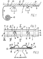
- components of the light rail system according to the invention are at least one conductor rail 2 and at least one luminaire holder 4 for luminaires 6, wherein — as shown — in particular low-voltage reflector luminaires can be used.
- the conductor rail 2 has at least two current conductors 7, but it is within the scope of the invention to design the system according to the invention as a “multi-conductor system”, for example with three conductors 7 for series connections and the like (cf. FIGS. 9 and 10).
- the conductor rail 2 now consists of a flexible, plastically deformable, self-supporting support profile 8, which is also advantageously thermally stable, i.e. even with heating, which is caused in particular by the lights 6, maintains sufficient mechanical stability.
- the carrier profile 8 according to the invention can advantageously be rolled up to rolls 10 after its production as "yard goods” and unrolled again for assembly and - as indicated in Fig. 2 - very easily with a hand tool (scissors, sheet metal shears, side cutters) cut to the desired length.
- the carrier profile 8 in a first embodiment according to the invention consists of a flat, strip-shaped conductor strip 11, which in turn preferably consists of a carrier strip 12, which brings about the mechanical properties of the carrier profile 8 mentioned above, and - as in FIG. 2 shown - on only one surface or - according to FIGS. 9 and 10 - arranged on both surfaces of the carrier tape 12, the conductor tracks 14 forming the current conductors.
- the carrier tape 12 consists of a metal tape 16, preferably an aluminum tape, an insulating layer 18 being preferably arranged on the metal tape 16 on both surfaces.
- the conductor tracks 14 are arranged on one of these insulating layers 18.
- the metal tape 16 can be used as an additional current conductor according to the invention.
- the metal strip 16 can advantageously be contacted (not shown) by means of contact elements penetrating the insulating layer 18.
- the carrier strip 12 in a e.g. 7, alternative embodiment of the conductor strip 8 illustrated in FIG. 7, the carrier strip 12 according to the invention consists uniformly of an electrically insulating material, in particular a plastic, this material then having the mechanical properties mentioned above.
- the conductor tracks 14 can also have these mechanical properties, in which case any plastic can be used for the carrier tape 12.
- a plurality of mounting elements 20 spaced apart from one another in the longitudinal direction of the conductor strip 8 are provided for fastening the carrier profile 8 to wall and / or ceiling surfaces 22.
- These assembly elements 20 consequently form spacers or fastening bases, the carrier profile 8 being preferably releasably attachable to the assembly elements 20.
- the mounting elements 20 can be designed as a "mounting clip", which in the execution of the Carrier profile 8 as a conductor strip 11 each have the longitudinal edges of the conductor strip 11 laterally encompassing, preferably spring-elastic holding arms 24.
- the carrier profile 8 can be connected to the mounting elements 20 according to the invention by means of snap-fit or force fit connections, in that it only needs to be pressed in between the holding arms 24 in a latching manner.
- the carrier profile 8 can also advantageously be integrally connected to the mounting elements 20, for example by means of adhesive strips 26 shown in broken lines, in order to absolutely prevent the carrier profile 8 from slipping.
- the mounting elements 20 are attached directly to the respective wall or ceiling surface 22, for example via screw connections 28.
- the mounting elements 20 are each indirectly attached to the surface 22 via a mounting part 30, in which case the mounting element 20 with the mounting part 30, which forms a spacer, is pivoted and / or via a hinge connection 32 is rotatably connected.
- This pivoting mobility is indicated in FIG. 6 by the double arrows 34 shown.
- This articulated mounting of the mounting part 30 brings about the possibility of adjusting the direction of radiation of the lamps 6 held on the carrier profile 8.
- the mounting elements 20 can advantageously also be designed as lampholders, the mounting elements 20 then each having the connecting elements electrically connecting the current conductors of the carrier profile 8 to contact elements of the lampholder.
- the lampholders 4 are each held in a non-positively and / or form-fitting manner in regions of the carrier profile 8 lying between the mounting elements 20.
- the lampholders 4 are arranged lying on the side of the conductor strip 11 facing away from the conductor tracks 14 and each penetrate a through opening 38 of the conductor strip 11 with electrical, preferably spring-elastic contact elements 36 (see FIG. 2) and lie on the other Side of the conductor strip 11 for contacting the conductor tracks 14 on this.
- the contact elements 36 can also grip around the side edges of the conductor strip 11 on the outside and then rest on the conductor tracks 14 on the other side of the conductor strip 11.
- the openings 38 of the conductor strip 11 can be prefabricated directly during the manufacture of the conductor strip 11. It is particularly advantageous that it can always be determined from the number of openings 38 of pieces of conductor strip 11 cut to different lengths which total connected load is present, since only the connected load of a lamp 6 multiplied by the number of available openings 38 are needed.
- the lampholders 4 advantageously each consist of a contact part 40 that can be connected to the carrier profile 8 or the conductor strip 11 and a socket part 42 that receives the luminaire 6 Conductor strip 11 are used in a bayonet-like manner, ie the contact part 40 has an elongated, preferably rectangular, contour adapted to the opening 38, as a result of which it is in a position in a direction perpendicular to the band plane (arrow direction 44 in FIG. 7) can be inserted into the opening 38. Subsequently, the contact part 40 is then rotated in the band plane in the double arrow direction 46 according to FIG. 8 until its contact elements contact the conductor tracks 14 (see FIG. 7).
- the holder part 42 can be connected to the contact part 40 so as to be pivotable and / or rotatable via at least one joint 48 (FIG. 7), in order to provide an adjustment option for the direction of radiation of the lamp 6.
- the mobility of the lamp 6 is illustrated in FIG. 7 by a double arrow 50.
- connection element 52 is further provided according to the invention, which connects the current conductors 7 of the carrier profile 8, i.e. the conductor tracks 14 and / or the metal strip 16, with connections of a voltage source, in particular a transformer 54, e.g. connects via a line connection 56.
- This connecting element is preferably designed as a plug-in element with a plug-in receptacle for inserting one end of the carrier profile 8.
- At least one connector element 58 can be provided for connecting two or more sections of the carrier profile 8.
- This connector element 58 preferably has a plug receptacle for each section of the carrier profile 8 to be connected, wherein these plug receptacles can be arranged at any angle to one another.
- 4 shows a corner connector for connecting two carrier profile sections at an angle of 90 °.
- T-connectors or star connectors are also conceivable.
- FIG. 9 and 10 show a further embodiment of the carrier profile 8 according to the invention, which in turn is designed as a conductor strip 11, but this conductor strip 11 consists of a central insulating layer 18 with conductor tracks 14 arranged on both sides.
- this conductor strip 11 consists of a central insulating layer 18 with conductor tracks 14 arranged on both sides.
- there are one side of the conductor strip 11 a conductor track 14 and two conductor tracks 14 arranged on the other side.
- the conductor tracks 14 bring about the mechanical properties of the carrier profile 8 according to the invention described above.
- This carrier profile 8 is particularly suitable for mounting or alignment perpendicular to a wall or ceiling surface 22, as shown in FIG. 10.
- the conductor tracks 14 are then contacted from the side by means of a suitable contact part 40. As shown in FIG.
- the contact part 40 consists of two parts 40a, 40b, which are detachably connected to one another via electrical connectors 62, which is to be illustrated by the double arrow 64 shown in FIG. 9.
- the mounting element 20 shown in FIG. 10 for this embodiment of the carrier profile 8 is essentially U-shaped and engages around the carrier profile 8 with two holding arms 66 in a latching or clamping manner.
- This mounting element 20 can - as shown - be attached directly or alternatively indirectly to the wall or ceiling surface 22 analogously to FIG. 6.
- the carrier profile 8 in the exemplary embodiment according to FIG. 11, consists of a band-shaped or strip-shaped carrier band 12 made of insulation material, in which a plurality of conductor tracks 14 are arranged one above the other in a sandwich-like arrangement are embedded. These conductor tracks 14 each extend as far as the side edges of the carrier profile 8, so that contact can be made in the region of the side edges in the manner shown in FIG. 11.
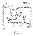
- FIG. 12 shows an example of how variably the light rail system according to the invention can be installed.
- the support profile 8 according to the invention can be laid in any course due to its flexibility and its dimensionally stable properties.
- 12 shows two intersecting strands of the carrier profile 8, a star-shaped connector element 58 with four plug-in receptacles being arranged at the crossing point. It is particularly advantageous here if the connector element 58 has electrical switching means by means of which the individual partial strands of the carrier profile 8 can be electrically connected or separated.
- the carrier profile 8 consists of a profile body 70 consisting of insulation material, this profile body 70 preferably having an edge-open, cross-sectionally approximately ⁇ -shaped conductor groove 72 for each current conductor 7, in which the respective Current conductor 7 is in particular held positively and recessed.
- the current conductors 7 are preferably designed as wires, in particular as copper wires with a circular cross section.
- the carrier profile 8 can obtain its mechanical properties according to the invention from the corresponding properties of the current conductors 7.
- the profile body 70 is a flexible, self-supporting, plastically deformable support element that runs in the longitudinal direction of the profile 74 has.
- This support element 74 is preferably embedded as a soul in the plastic profile body 70.
- the support element 74 has a circular cross section. It can consist of metal, in particular aluminum.
- the profile body 70 has, in addition to the conductor grooves 72, further edge-open receiving grooves 76 for preferably also positive and recessed receiving additional conductors 78.
- additional conductors 78 can be used for any functions, such as speaker lines, control lines or the like.
- the profile body 70 is in each case formed with an essentially rectangular cross section, the current conductors 7 and / or the additional conductors 78 being arranged in the region of a surface of the profile body 70 according to FIGS. 13, 15, 16 and 17.
- a current conductor 7 is arranged on diametrically opposite side surfaces of the profile body 70, while the additional conductors 78 are arranged on one of the surfaces of the profile body 70 connecting these two opposite sides.
- the lampholders 4 or their contact parts 40 each have contact elements 80 which, according to the invention, engage in the conductor grooves 72 and / or the receiving grooves 76 of the profile body 70 in such a way that they conduct the conductors 7 arranged there. 78 contact.
- the openings of the conductor grooves 72 and the receiving grooves 76 can advantageously be so narrow that contact with the live conductors is excluded.
- a cover profile 82 which can be connected to the carrier profile 8 in a force-fitting and / or form-fitting and / or material-locking manner is provided, which preferably closes the conductor grooves 72 and / or the receiving grooves 76 in a watertight manner.
- This version is particularly advantageous for outdoor installation, since it protects the current conductors 7 and / or the additional conductors 78 from moisture and moisture.
- the lamp holders 4 on the support profile 8 or the profile body 70 are displaceable in the longitudinal direction of the profile and are preferably driven by a motor.
- the lampholder 4 or the contact part 40 has a rotatably mounted shaft 84 which can be driven via a motor drive 86 and on the other side carries a gear 88 which engages in a toothed rack 90 of the carrier profile 8 or the profile body 70.
- the motor drive 86 can be controlled via the additional conductors 78 (not shown in FIG. 17).
- the contact elements 80 are designed as sliding contacts, so that the conductors 7 and 78 are well contacted even during the displacement movement. This embodiment is particularly suitable for effect lighting, for example in discotheques and the like.
Claims (20)
- Système à barre omnibus d'éclairage, comportant une barre conductrice (2) avec au moins deux conducteurs (7), et au moins une douille (4) pour dispositif d'éclairage, en particulier pour dispositifs d'éclairage à basse tension, pouvant être reliée à la barre conductrice (2) par contact avec les conducteurs (7)
caractérisé en ce que la barre conductrice (2) est formée par un profilé porteur (8) qui est premièrement flexible de manière à pouvoir être enroulé, qui est deuxièmement déformable plastiquement de manière à pouvoir être monté selon n'importe quelle orientation, et qui troisièmement présente des propriétés autoporteuses telles qu'il possède dans la région entre deux éléments de montage (20), prévus pour le montage sur des parois ou sur le plafond, et séparés dans la direction longitudinale du profilé, une stabilité telle qu'il est possible de prévoir dans cette région la fixation d'au moins une douille (4) sans déformation sensible par le poids de la douille (4). - Système à barre omnibus d'éclairage selon la revendication 1,
caractérisé en ce que le profilé porteur (8) a la forme d'une bande conductrice (11) plate en forme de ruban et consiste de préférence en une bande de support (12) sur l'une des faces ou sur ou dans les deux faces de laquelle sont disposées ou encastrées des pistes conductrices (14) constituant les conducteurs (7). - Système à barre omnibus d'éclairage selon la revendication 2,
caractérisé en ce que la bande de support (12) consiste en une bande métallique (16), en particulier une bande en aluminium, munie de préférence sur ses deux faces d'une couche d'isolation (18), ou bien consiste en une matière électriquement isolante, en particulier une matière synthétique. - Système à barre omnibus d'éclairage selon la revendication 3,
caractérisé en ce que la bande métallique (16) de la bande de support (12) forme un conducteur, contactable en particulier par des éléments de contact qui passent à travers la couche d'isolation (18). - Système à barre omnibus d'éclairage selon la revendication 1,
caractérisé en ce que le profilé porteur (8) consiste en un corps profilé tridimensionnel (70) en une matière isolante comportant de préférence des gorges (72) à bords ouverts qui reçoivent les conducteurs (7), en particulier par emboîtage et encastrage. - Système à barre omnibus d'éclairage selon la revendication 5,
caractérisé en ce que le corps profilé (70) présente un élément porteur (74) s'étendant dans la direction longitudinale du profilé et possédant les propriétés susmentionnées : souple, plastiquement déformable et autoporteur, ledit élément étant de préférence encastré en tant qu'âme dans le corps profilé en matière synthétique (70) et étant réalisé en particulier en métal, de préférence en aluminium. - Système à barre omnibus d'éclairage selon la revendication 5 ou 6,
caractérisé en ce que le corps profilé (70) présente, en plus des gorges (72), d'autres gorges de réception à bords ouverts (76) pour accueillir, de préférence par emboîtement, des conducteurs supplémentaires (78). - Système à barre omnibus d'éclairage selon l'une ou plusieurs des revendications 5 à 7,
caractérisé par un profilé de couverture (82) pouvant être relié au profilé porteur (8) par force et/ou par la forme et/ou la matière, et fermant les gorges (72) et/ou les gorges de réception (76) de préférence de manière étanche à l'eau. - Système à barre omnibus d'éclairage selon l'une ou plusieurs des revendications 1 à 8,
caractérisé en ce que le profilé porteur (8) peut être connecté aux éléments de montage (20), en particulier par des liaisons encliquetables, par la forme, ou la force et/ou la matière. - Système à barre omnibus d'éclairage selon l'une ou plusieurs des revendications 1 à 9,
caractérisé en ce que les éléments de montage (20) peuvent être fixés directement ou respectivement par une pièce de montage (30) sur une surface de plafond ou de paroi (22), l'élément de montage (20) étant de préférence relié à la pièce de montage (30) de manière pivotante et/ou rotative par une articulation (32). - Système à barre omnibus d'éclairage selon l'une ou plusieurs des revendications 1 à 10,
caractérisé en ce que les éléments de montage (20) servent en même temps de douilles pour les dispositifs d'éclairage, les éléments de montage (20) comportant des éléments de connexion reliant respectivement les conducteurs du profilé porteur (8) aux éléments de contact de la douille (4). - Système à barre omnibus d'éclairage selon l'une ou plusieurs des revendications 1 à 11,
caractérisé en ce que la douille (4) est maintenue sur le profilé porteur (8) par force et/ou par la forme, de préférence au moyen de connexions par la forme ou par force encliquetables. - Système à barre omnibus d'éclairage selon la revendication 12,
caractérisé en ce que les douilles (4) sont disposées sur une face du profilé porteur en forme de ruban conducteur (11), des éléments de contact électrique (36), de préférence souples, de ces douilles (4) passant à travers des ouvertures (38) de la bande conductrice (11), ou entourent par l'extérieur les bords latéraux de celle-ci, et en ce que, de l'autre côté de la bande conductrice (11), les pistes conductrices (14) sont disposées sur et en contact avec lesdits éléments de contact. - Système à barre omnibus d'éclairage selon la revendication 12,
caractérisé en ce que des éléments de contact (80) des douilles (4) s'engagent dans les gorges (72) et/ou les gorges de réception (76) du profilé porteur (8) en forme de corps profilé (70) et entrent en contact avec les conducteurs (7) et/ou les conducteurs supplémentaires (78). - Système à barre omnibus d'éclairage selon l'une ou plusieurs des revendications 1 à 14,
caractérisé en ce que les douilles (4) comportent respectivement une partie de contact (40) pouvant être reliée au profilé porteur (8), et une partie douille (42) qui reçoit le dispositif d'éclairage (6), la partie douille (42) étant de préférence reliée par au moins une articulation (48) de manière pivotante et/ou rotative à la partie de contact (40). - Système à barre omnibus d'éclairage selon la revendication 15,
caractérisé en ce que la partie de contact (40) est formée par deux portions (40a, 40b) pouvant être reliées entre elles de manière amovible par deux connecteurs électriques (62), la portion (40a) pouvant être reliée au profilé porteur (8), et l'autre portion (40b) étant reliée à la partie douille (42). - Système à barre omnibus d'éclairage selon l'une ou plusieurs des revendications 1 à 16,
caractérisé par au moins un élément de connexion (52) qui relie les conducteurs (7) du profilé porteur (8) à des connexions d'une source de tension, en particulier d'un transformateur (54). - Système à barre omnibus d'éclairage selon l'une des revendications 1 à 17,
caractérisé par au moins un élément de liaison (58) pour relier de manière mécanique et/ou électrique deux ou plusieurs sections du profilé porteur (8) formant de préférence un angle entre elles. - Système à barre omnibus d'éclairage selon la revendication 17 et/ou 18,
caractérisé en ce que l'élément de connexion (52) et/ou l'élément de liaison (58) comporte(nt) des moyens de commutation pour établir et interrompre les liaisons électriques entre la source de tension et les conducteurs (7) et/ou entre les conducteurs (7) des différentes sections du profilé porteur (8). - Système à barre omnibus d'éclairage selon l'une des revendications 1 à 19,
caractérisé en ce que les douilles (4) peuvent coulisser et sont de préférence entraînées par un moteur, sur le profilé porteur (8) dans la direction longitudinale de celui-ci.
Priority Applications (3)
| Application Number | Priority Date | Filing Date | Title |
|---|---|---|---|
| DE58909735T DE58909735D1 (de) | 1989-06-28 | 1989-06-28 | Lichtschienen-System |
| EP19890111772 EP0404979B1 (fr) | 1989-06-28 | 1989-06-28 | Système de rail d'éclairage |
| ES89111772T ES2094116T3 (es) | 1989-06-28 | 1989-06-28 | Sistema de regletas luminosas. |
Applications Claiming Priority (1)
| Application Number | Priority Date | Filing Date | Title |
|---|---|---|---|
| EP19890111772 EP0404979B1 (fr) | 1989-06-28 | 1989-06-28 | Système de rail d'éclairage |
Publications (2)
| Publication Number | Publication Date |
|---|---|
| EP0404979A1 EP0404979A1 (fr) | 1991-01-02 |
| EP0404979B1 true EP0404979B1 (fr) | 1996-09-18 |
Family
ID=8201546
Family Applications (1)
| Application Number | Title | Priority Date | Filing Date |
|---|---|---|---|
| EP19890111772 Expired - Lifetime EP0404979B1 (fr) | 1989-06-28 | 1989-06-28 | Système de rail d'éclairage |
Country Status (3)
| Country | Link |
|---|---|
| EP (1) | EP0404979B1 (fr) |
| DE (1) | DE58909735D1 (fr) |
| ES (1) | ES2094116T3 (fr) |
Cited By (3)
| Publication number | Priority date | Publication date | Assignee | Title |
|---|---|---|---|---|
| US9303854B2 (en) | 2013-03-12 | 2016-04-05 | Apex Technologies, Inc. | Electrical rail systems with axially interleaved contact arrays |
| US10132452B2 (en) | 2013-03-14 | 2018-11-20 | Apex Technologies, Inc. | Suspended track and planar electrode systems and methods |
| US10680383B2 (en) | 2013-03-14 | 2020-06-09 | Apex Technologies, Inc. | Linear electrode systems for module attachment with non-uniform axial spacing |
Families Citing this family (11)
| Publication number | Priority date | Publication date | Assignee | Title |
|---|---|---|---|---|
| DE19510507C2 (de) * | 1995-03-23 | 1999-11-18 | Alulite Lichtsysteme Gmbh | Elektrisches Leuchtensystem |
| DE29600747U1 (de) * | 1996-01-17 | 1996-03-07 | Wonnemann Andreas | Lichterkette |
| EP0822625A3 (fr) * | 1996-04-22 | 1998-12-09 | Holtkötter Leuchten GmbH | Système de rail 12 Volt sur lequel peut être connectée, à un endroit quelconque, une source lumineuse |
| BE1010401A3 (nl) * | 1996-07-02 | 1998-07-07 | Gieraerts Eddy Jozef Ghislain | Armatuur. |
| BE1010396A3 (nl) * | 1996-07-02 | 1998-07-07 | Gieraerts Eddy Jozef Ghislain | Lamparmatuur. |
| DE19745048C2 (de) * | 1997-10-11 | 2001-04-12 | Verbeek Leuchten Gmbh | Stromverteil- und -abnahmesystem |
| DE29905052U1 (de) * | 1999-03-19 | 1999-06-02 | Dornier Gmbh Lindauer | Einrichtung zur Bedienung von Webmaschinen |
| DE10226761A1 (de) * | 2002-06-14 | 2004-01-08 | Patent-Treuhand-Gesellschaft für elektrische Glühlampen mbH | Bajonettsockel für Lampenhalterung |
| DE20314831U1 (de) * | 2003-09-23 | 2004-02-26 | Bruck, Jochen | Stromschienenanordnung für Niedervoltlampen und Leuchtdioden |
| DE202005005567U1 (de) * | 2005-04-07 | 2006-08-17 | Paulmann Licht Gmbh | Haltevorrichtung für eine Leuchte |
| DE102005016512A1 (de) * | 2005-04-11 | 2006-10-12 | Ingo Maurer Gmbh | Beleuchtungssystem |
Family Cites Families (2)
| Publication number | Priority date | Publication date | Assignee | Title |
|---|---|---|---|---|
| GB2150766B (en) * | 1983-05-17 | 1987-11-18 | Tulla Lighting Limited | Track lighting |
| FR2623030A1 (fr) * | 1987-11-09 | 1989-05-12 | Lepaillier Patrick | Dispositif d'alimentation electrique d'un support pour la fixation de materiel electrique et/ou electronique a un rail |
-
1989
- 1989-06-28 DE DE58909735T patent/DE58909735D1/de not_active Expired - Fee Related
- 1989-06-28 EP EP19890111772 patent/EP0404979B1/fr not_active Expired - Lifetime
- 1989-06-28 ES ES89111772T patent/ES2094116T3/es not_active Expired - Lifetime
Cited By (3)
| Publication number | Priority date | Publication date | Assignee | Title |
|---|---|---|---|---|
| US9303854B2 (en) | 2013-03-12 | 2016-04-05 | Apex Technologies, Inc. | Electrical rail systems with axially interleaved contact arrays |
| US10132452B2 (en) | 2013-03-14 | 2018-11-20 | Apex Technologies, Inc. | Suspended track and planar electrode systems and methods |
| US10680383B2 (en) | 2013-03-14 | 2020-06-09 | Apex Technologies, Inc. | Linear electrode systems for module attachment with non-uniform axial spacing |
Also Published As
| Publication number | Publication date |
|---|---|
| DE58909735D1 (de) | 1996-10-24 |
| EP0404979A1 (fr) | 1991-01-02 |
| ES2094116T3 (es) | 1997-01-16 |
Similar Documents
| Publication | Publication Date | Title |
|---|---|---|
| DE10025648B4 (de) | Stromschienensystem | |
| EP1141624B1 (fr) | Systeme de rampes lumineuses et procede de montage d'un tel systeme | |
| EP2026425B1 (fr) | Système de rail conducteur | |
| EP0404979B1 (fr) | Système de rail d'éclairage | |
| DE7809825U1 (de) | Kupplungsstück | |
| DE19849101A1 (de) | Stromschienensystem | |
| CH663291A5 (de) | Stromschiene mit stromentnahmevorrichtung. | |
| EP1284035B1 (fr) | Systeme de rails conducteurs | |
| EP0307396B1 (fr) | Appareil d'eclairage | |
| DE2243686A1 (de) | Elektrische stromleistenanordnung mit verbindungsdosen-system | |
| AT408162B (de) | Adapter, stromschiene und kupplungsvorrichtung | |
| EP0795216A1 (fr) | Dispositif d'alimentation en courant pour appareils basse tension | |
| DE3245384A1 (de) | Elektrische stromschiene zur stromversorgung sowie dazugehoerige anschlussvorrichtung | |
| DE4032622C2 (fr) | ||
| DE3817133C2 (fr) | ||
| EP2867961B1 (fr) | Système de canal | |
| DE19652401C2 (de) | Stromschienensystem | |
| DE10216250B4 (de) | Endstück für eine Stromschiene eines Stromschienensystems | |
| EP1841013A1 (fr) | Dispositif d'éclairage | |
| DE19750100C2 (de) | Verbindungsvorrichtung | |
| DE3919201A1 (de) | Stromschiene mit leuchte | |
| DE3007970A1 (de) | Elektrische schaltanlage | |
| DE2538199A1 (de) | Anschlussklemme fuer elektrische leitungen | |
| DE3806241A1 (de) | Installationseinrichtung fuer niedervolt-leuchten | |
| DE102012107907A1 (de) | Leuchtenmodul und Verfahren zu dessen Montage |
Legal Events
| Date | Code | Title | Description |
|---|---|---|---|
| PUAI | Public reference made under article 153(3) epc to a published international application that has entered the european phase |
Free format text: ORIGINAL CODE: 0009012 |
|
| 17P | Request for examination filed |
Effective date: 19891108 |
|
| AK | Designated contracting states |
Kind code of ref document: A1 Designated state(s): DE ES FR GB IT NL SE |
|
| 17Q | First examination report despatched |
Effective date: 19930317 |
|
| GRAH | Despatch of communication of intention to grant a patent |
Free format text: ORIGINAL CODE: EPIDOS IGRA |
|
| GRAH | Despatch of communication of intention to grant a patent |
Free format text: ORIGINAL CODE: EPIDOS IGRA |
|
| GRAA | (expected) grant |
Free format text: ORIGINAL CODE: 0009210 |
|
| AK | Designated contracting states |
Kind code of ref document: B1 Designated state(s): DE ES FR GB IT NL SE |
|
| PG25 | Lapsed in a contracting state [announced via postgrant information from national office to epo] |
Ref country code: GB Effective date: 19960918 |
|
| REF | Corresponds to: |
Ref document number: 58909735 Country of ref document: DE Date of ref document: 19961024 |
|
| ITF | It: translation for a ep patent filed |
Owner name: ING. A. GIAMBROCONO & C. S.R.L. |
|
| PG25 | Lapsed in a contracting state [announced via postgrant information from national office to epo] |
Ref country code: SE Effective date: 19961218 |
|
| ET | Fr: translation filed | ||
| REG | Reference to a national code |
Ref country code: ES Ref legal event code: FG2A Ref document number: 2094116 Country of ref document: ES Kind code of ref document: T3 |
|
| GBV | Gb: ep patent (uk) treated as always having been void in accordance with gb section 77(7)/1977 [no translation filed] |
Effective date: 19960918 |
|
| PLBE | No opposition filed within time limit |
Free format text: ORIGINAL CODE: 0009261 |
|
| STAA | Information on the status of an ep patent application or granted ep patent |
Free format text: STATUS: NO OPPOSITION FILED WITHIN TIME LIMIT |
|
| 26N | No opposition filed | ||
| PGFP | Annual fee paid to national office [announced via postgrant information from national office to epo] |
Ref country code: FR Payment date: 20010411 Year of fee payment: 13 |
|
| PGFP | Annual fee paid to national office [announced via postgrant information from national office to epo] |
Ref country code: ES Payment date: 20010605 Year of fee payment: 13 |
|
| PGFP | Annual fee paid to national office [announced via postgrant information from national office to epo] |
Ref country code: NL Payment date: 20010630 Year of fee payment: 13 |
|
| PGFP | Annual fee paid to national office [announced via postgrant information from national office to epo] |
Ref country code: DE Payment date: 20010813 Year of fee payment: 13 |
|
| PG25 | Lapsed in a contracting state [announced via postgrant information from national office to epo] |
Ref country code: ES Free format text: LAPSE BECAUSE OF NON-PAYMENT OF DUE FEES Effective date: 20020629 |
|
| PG25 | Lapsed in a contracting state [announced via postgrant information from national office to epo] |
Ref country code: NL Free format text: LAPSE BECAUSE OF NON-PAYMENT OF DUE FEES Effective date: 20030101 Ref country code: DE Free format text: LAPSE BECAUSE OF NON-PAYMENT OF DUE FEES Effective date: 20030101 |
|
| PG25 | Lapsed in a contracting state [announced via postgrant information from national office to epo] |
Ref country code: FR Free format text: LAPSE BECAUSE OF NON-PAYMENT OF DUE FEES Effective date: 20030228 |
|
| NLV4 | Nl: lapsed or anulled due to non-payment of the annual fee |
Effective date: 20030101 |
|
| REG | Reference to a national code |
Ref country code: FR Ref legal event code: ST |
|
| REG | Reference to a national code |
Ref country code: ES Ref legal event code: FD2A Effective date: 20030711 |
|
| PG25 | Lapsed in a contracting state [announced via postgrant information from national office to epo] |
Ref country code: IT Free format text: LAPSE BECAUSE OF NON-PAYMENT OF DUE FEES;WARNING: LAPSES OF ITALIAN PATENTS WITH EFFECTIVE DATE BEFORE 2007 MAY HAVE OCCURRED AT ANY TIME BEFORE 2007. THE CORRECT EFFECTIVE DATE MAY BE DIFFERENT FROM THE ONE RECORDED. Effective date: 20050628 |