EP0404979B1 - Light rail system - Google Patents
Light rail system Download PDFInfo
- Publication number
- EP0404979B1 EP0404979B1 EP19890111772 EP89111772A EP0404979B1 EP 0404979 B1 EP0404979 B1 EP 0404979B1 EP 19890111772 EP19890111772 EP 19890111772 EP 89111772 A EP89111772 A EP 89111772A EP 0404979 B1 EP0404979 B1 EP 0404979B1
- Authority
- EP
- European Patent Office
- Prior art keywords
- profile
- bus bar
- conductor
- bar system
- girder
- Prior art date
- Legal status (The legal status is an assumption and is not a legal conclusion. Google has not performed a legal analysis and makes no representation as to the accuracy of the status listed.)
- Expired - Lifetime
Links
Images


Classifications
-
- H—ELECTRICITY
- H01—ELECTRIC ELEMENTS
- H01R—ELECTRICALLY-CONDUCTIVE CONNECTIONS; STRUCTURAL ASSOCIATIONS OF A PLURALITY OF MUTUALLY-INSULATED ELECTRICAL CONNECTING ELEMENTS; COUPLING DEVICES; CURRENT COLLECTORS
- H01R25/00—Coupling parts adapted for simultaneous co-operation with two or more identical counterparts, e.g. for distributing energy to two or more circuits
- H01R25/14—Rails or bus-bars constructed so that the counterparts can be connected thereto at any point along their length
- H01R25/147—Low voltage devices, i.e. safe to touch live conductors
-
- F—MECHANICAL ENGINEERING; LIGHTING; HEATING; WEAPONS; BLASTING
- F21—LIGHTING
- F21V—FUNCTIONAL FEATURES OR DETAILS OF LIGHTING DEVICES OR SYSTEMS THEREOF; STRUCTURAL COMBINATIONS OF LIGHTING DEVICES WITH OTHER ARTICLES, NOT OTHERWISE PROVIDED FOR
- F21V21/00—Supporting, suspending, or attaching arrangements for lighting devices; Hand grips
- F21V21/34—Supporting elements displaceable along a guiding element
- F21V21/35—Supporting elements displaceable along a guiding element with direct electrical contact between the supporting element and electric conductors running along the guiding element
Definitions
- the present invention relates to a light rail system with a conductor rail having at least two current conductors and at least one lamp holder which can be connected to the conductor rail by contacting the current conductors, in particular for low-voltage lamps.
- light rail systems are known, the conductor rails of which consist of rigid, for example U-shaped profile rails in cross section, the sockets for the lamps being held by grooves formed in the U-shaped receptacle and being contacted with conductors arranged in these regions.
- the assembly of these systems is also complex.
- only light rails can always be realized with a length corresponding to the length of a profile rail or a multiple thereof, unless one of the profile rails is to be shortened, but this is only possible by sawing or the like and is therefore difficult.
- a light rail system of the generic type is also known from document EP-A-0 129 425.
- essentially rigid light rails are provided, which are not very variable in terms of the mounting possibility, namely mainly a two-part rail consisting of a conductor rail and a channel profile used for holding is described.
- the object of the present invention is to improve a light rail system of the generic type in such a way that it can be assembled more easily, more quickly and with greater variability in terms of spatial arrangement and mounting options, and in particular also meets today's safety regulations.
- the conductor rail consists of a carrier profile which, firstly, is designed to be so flexible that it can be rolled up, which, secondly, is plastically deformable in such a way that it can be mounted with practically any directional course, and thirdly, has such self-supporting properties that it has such stability in the area between two wall elements or ceiling elements, spaced apart in the longitudinal direction of the profile, that In this area it is possible to attach at least one luminaire holder without significant changes in shape due to the weight of the luminaire holder.
- the carrier profile is designed as a flat, strip-shaped conductor strip and preferably consists of a carrier strip with on one side or on both sides of the carrier strip arranged, forming the current conductors, electrically insulated from each other.
- the carrier tape itself preferably consists of a metal tape, in particular an aluminum tape, with insulating layers applied on both sides, it being possible for the insulating layers to be formed from anodized layers of the aluminum tape and / or from additional insulation material.
- the metal strip in particular gives the carrier profile according to the invention its plastic deformability and self-supporting properties.
- the carrier tape from an electrically insulating material, in particular from plastic, in which case this plastic preferably has the abovementioned properties, flexibility, plastic deformability and self-supporting properties, but these properties can also affect the carrier profile are given to the current conductors or the conductor tracks by forming them with appropriate material properties.
- the support profile is due to its band shape in directions perpendicular to the band plane, i.e. "in two dimensions", deformable.
- the conductor strip can be “laid” in any direction and course, for example by twisting (twisting) it.
- the conductor strip can be mounted either parallel or perpendicular to wall or ceiling surfaces using suitable mounting elements, which also has a positive influence on the mounting and routing options.
- the support profile is in relation to its cross section three-dimensional, ie non-band-shaped profile body made of insulation material, which profile body can have a flat cross-section, in particular an approximately rectangular or square or a circular, oval, triangular or other polygonal cross-section or a "superimposition" of these cross-sectional shapes.
- the profile body preferably has a conductor groove which is open at the edge and in which the current conductor is seated, in particular in a form-fitting and recessed manner, ie protected against contact. The contact is made by means of contact elements engaging in the conductor grooves.
- the mechanical properties mentioned above are achieved either by the current conductors, for example made of copper wires, or - which is particularly advantageous - by a special support element, which is preferably embedded as a core in the plastic profile body. It is particularly advantageous in this embodiment that the carrier profile can be deformed as desired in practically any spatial direction, ie "in three dimensions".
- the profile body has, in addition to the conductor grooves, any number of receiving grooves, likewise open at the edge, in which additional conductors for any functions, for example as telephone, loudspeaker or control lines, are arranged.
- the carrier profile according to the invention is so flexible on the one hand that it can advantageously be stored and transported in a rolled-up state as "yard goods" in a very space-saving manner, but on the other hand still has such rigidity that it is plastically deformable and in the assembled state receives "self-supporting" properties.
- the support profile for example in the area between two to the wall or Provided ceiling mounting, spaced apart from each other in the longitudinal direction of the profile has such stability that it is possible to attach a luminaire holder in this area without substantial changes in shape (bending) occurring due to the weight of the luminaire holder and the luminaire arranged therein.
- the carrier profile according to the invention advantageously has only such a cross section that it can still be cut to length with a hand tool, for example with scissors or a side cutter.
- the support profile according to the invention is thus advantageously extremely simple and very variable to assemble.
- the light rail system according to the invention also meets the applicable safety regulations, since it is preferably designed and / or mounted in such a way that the current conductors are concealed or at least recessed in the support profile. As a result, short circuits and contact with the live or live conductors are almost impossible.
- the light rail system according to the invention is extremely variable with regard to its possible uses.
- the carrier profile is preferably fastened to wall and / or ceiling surfaces by means of mounting elements spaced apart from one another in the longitudinal direction of the profile, the mounting elements being able to form spacers, so that the carrier profile runs parallel to the respective surface at a small distance.
- connection element For connection to a voltage source, according to the invention at least one connection element is provided which connects the current conductors of the carrier profile with connections of the voltage source, for example a transformer preferably has a plug-in receptacle for inserting one end of the carrier profile. Contact elements are arranged in the plug receptacle which make electrical contact with the current conductors of the carrier profile.
- the connector element can also only be a mechanical, i.e. Establish non-conductive connection of the carrier profile sections; Furthermore, it can advantageously have switching means by means of which the current conductors of the respective carrier profile sections can optionally be electrically connected or disconnected. It can be corner connectors, T-connectors, star connectors with multiple outlets or the like.
- the connector element also advantageously has, for each section of the carrier profile, a plug-in receptacle receiving it at the end with contact elements contacting the current conductors.
- the angle or angles between the individual outlets of the connector element can either lie in the band plane of the carrier profile designed as a conductor band and / or in each case between the band levels of two conductor bands.
- components of the light rail system according to the invention are at least one conductor rail 2 and at least one luminaire holder 4 for luminaires 6, wherein — as shown — in particular low-voltage reflector luminaires can be used.
- the conductor rail 2 has at least two current conductors 7, but it is within the scope of the invention to design the system according to the invention as a “multi-conductor system”, for example with three conductors 7 for series connections and the like (cf. FIGS. 9 and 10).
- the conductor rail 2 now consists of a flexible, plastically deformable, self-supporting support profile 8, which is also advantageously thermally stable, i.e. even with heating, which is caused in particular by the lights 6, maintains sufficient mechanical stability.
- the carrier profile 8 according to the invention can advantageously be rolled up to rolls 10 after its production as "yard goods” and unrolled again for assembly and - as indicated in Fig. 2 - very easily with a hand tool (scissors, sheet metal shears, side cutters) cut to the desired length.
- the carrier profile 8 in a first embodiment according to the invention consists of a flat, strip-shaped conductor strip 11, which in turn preferably consists of a carrier strip 12, which brings about the mechanical properties of the carrier profile 8 mentioned above, and - as in FIG. 2 shown - on only one surface or - according to FIGS. 9 and 10 - arranged on both surfaces of the carrier tape 12, the conductor tracks 14 forming the current conductors.
- the carrier tape 12 consists of a metal tape 16, preferably an aluminum tape, an insulating layer 18 being preferably arranged on the metal tape 16 on both surfaces.
- the conductor tracks 14 are arranged on one of these insulating layers 18.
- the metal tape 16 can be used as an additional current conductor according to the invention.
- the metal strip 16 can advantageously be contacted (not shown) by means of contact elements penetrating the insulating layer 18.
- the carrier strip 12 in a e.g. 7, alternative embodiment of the conductor strip 8 illustrated in FIG. 7, the carrier strip 12 according to the invention consists uniformly of an electrically insulating material, in particular a plastic, this material then having the mechanical properties mentioned above.
- the conductor tracks 14 can also have these mechanical properties, in which case any plastic can be used for the carrier tape 12.
- a plurality of mounting elements 20 spaced apart from one another in the longitudinal direction of the conductor strip 8 are provided for fastening the carrier profile 8 to wall and / or ceiling surfaces 22.
- These assembly elements 20 consequently form spacers or fastening bases, the carrier profile 8 being preferably releasably attachable to the assembly elements 20.
- the mounting elements 20 can be designed as a "mounting clip", which in the execution of the Carrier profile 8 as a conductor strip 11 each have the longitudinal edges of the conductor strip 11 laterally encompassing, preferably spring-elastic holding arms 24.
- the carrier profile 8 can be connected to the mounting elements 20 according to the invention by means of snap-fit or force fit connections, in that it only needs to be pressed in between the holding arms 24 in a latching manner.
- the carrier profile 8 can also advantageously be integrally connected to the mounting elements 20, for example by means of adhesive strips 26 shown in broken lines, in order to absolutely prevent the carrier profile 8 from slipping.
- the mounting elements 20 are attached directly to the respective wall or ceiling surface 22, for example via screw connections 28.
- the mounting elements 20 are each indirectly attached to the surface 22 via a mounting part 30, in which case the mounting element 20 with the mounting part 30, which forms a spacer, is pivoted and / or via a hinge connection 32 is rotatably connected.
- This pivoting mobility is indicated in FIG. 6 by the double arrows 34 shown.
- This articulated mounting of the mounting part 30 brings about the possibility of adjusting the direction of radiation of the lamps 6 held on the carrier profile 8.
- the mounting elements 20 can advantageously also be designed as lampholders, the mounting elements 20 then each having the connecting elements electrically connecting the current conductors of the carrier profile 8 to contact elements of the lampholder.
- the lampholders 4 are each held in a non-positively and / or form-fitting manner in regions of the carrier profile 8 lying between the mounting elements 20.
- the lampholders 4 are arranged lying on the side of the conductor strip 11 facing away from the conductor tracks 14 and each penetrate a through opening 38 of the conductor strip 11 with electrical, preferably spring-elastic contact elements 36 (see FIG. 2) and lie on the other Side of the conductor strip 11 for contacting the conductor tracks 14 on this.
- the contact elements 36 can also grip around the side edges of the conductor strip 11 on the outside and then rest on the conductor tracks 14 on the other side of the conductor strip 11.
- the openings 38 of the conductor strip 11 can be prefabricated directly during the manufacture of the conductor strip 11. It is particularly advantageous that it can always be determined from the number of openings 38 of pieces of conductor strip 11 cut to different lengths which total connected load is present, since only the connected load of a lamp 6 multiplied by the number of available openings 38 are needed.
- the lampholders 4 advantageously each consist of a contact part 40 that can be connected to the carrier profile 8 or the conductor strip 11 and a socket part 42 that receives the luminaire 6 Conductor strip 11 are used in a bayonet-like manner, ie the contact part 40 has an elongated, preferably rectangular, contour adapted to the opening 38, as a result of which it is in a position in a direction perpendicular to the band plane (arrow direction 44 in FIG. 7) can be inserted into the opening 38. Subsequently, the contact part 40 is then rotated in the band plane in the double arrow direction 46 according to FIG. 8 until its contact elements contact the conductor tracks 14 (see FIG. 7).
- the holder part 42 can be connected to the contact part 40 so as to be pivotable and / or rotatable via at least one joint 48 (FIG. 7), in order to provide an adjustment option for the direction of radiation of the lamp 6.
- the mobility of the lamp 6 is illustrated in FIG. 7 by a double arrow 50.
- connection element 52 is further provided according to the invention, which connects the current conductors 7 of the carrier profile 8, i.e. the conductor tracks 14 and / or the metal strip 16, with connections of a voltage source, in particular a transformer 54, e.g. connects via a line connection 56.
- This connecting element is preferably designed as a plug-in element with a plug-in receptacle for inserting one end of the carrier profile 8.
- At least one connector element 58 can be provided for connecting two or more sections of the carrier profile 8.
- This connector element 58 preferably has a plug receptacle for each section of the carrier profile 8 to be connected, wherein these plug receptacles can be arranged at any angle to one another.
- 4 shows a corner connector for connecting two carrier profile sections at an angle of 90 °.
- T-connectors or star connectors are also conceivable.
- FIG. 9 and 10 show a further embodiment of the carrier profile 8 according to the invention, which in turn is designed as a conductor strip 11, but this conductor strip 11 consists of a central insulating layer 18 with conductor tracks 14 arranged on both sides.
- this conductor strip 11 consists of a central insulating layer 18 with conductor tracks 14 arranged on both sides.
- there are one side of the conductor strip 11 a conductor track 14 and two conductor tracks 14 arranged on the other side.
- the conductor tracks 14 bring about the mechanical properties of the carrier profile 8 according to the invention described above.
- This carrier profile 8 is particularly suitable for mounting or alignment perpendicular to a wall or ceiling surface 22, as shown in FIG. 10.
- the conductor tracks 14 are then contacted from the side by means of a suitable contact part 40. As shown in FIG.
- the contact part 40 consists of two parts 40a, 40b, which are detachably connected to one another via electrical connectors 62, which is to be illustrated by the double arrow 64 shown in FIG. 9.
- the mounting element 20 shown in FIG. 10 for this embodiment of the carrier profile 8 is essentially U-shaped and engages around the carrier profile 8 with two holding arms 66 in a latching or clamping manner.
- This mounting element 20 can - as shown - be attached directly or alternatively indirectly to the wall or ceiling surface 22 analogously to FIG. 6.
- the carrier profile 8 in the exemplary embodiment according to FIG. 11, consists of a band-shaped or strip-shaped carrier band 12 made of insulation material, in which a plurality of conductor tracks 14 are arranged one above the other in a sandwich-like arrangement are embedded. These conductor tracks 14 each extend as far as the side edges of the carrier profile 8, so that contact can be made in the region of the side edges in the manner shown in FIG. 11.
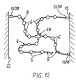
- FIG. 12 shows an example of how variably the light rail system according to the invention can be installed.
- the support profile 8 according to the invention can be laid in any course due to its flexibility and its dimensionally stable properties.
- 12 shows two intersecting strands of the carrier profile 8, a star-shaped connector element 58 with four plug-in receptacles being arranged at the crossing point. It is particularly advantageous here if the connector element 58 has electrical switching means by means of which the individual partial strands of the carrier profile 8 can be electrically connected or separated.
- the carrier profile 8 consists of a profile body 70 consisting of insulation material, this profile body 70 preferably having an edge-open, cross-sectionally approximately ⁇ -shaped conductor groove 72 for each current conductor 7, in which the respective Current conductor 7 is in particular held positively and recessed.
- the current conductors 7 are preferably designed as wires, in particular as copper wires with a circular cross section.
- the carrier profile 8 can obtain its mechanical properties according to the invention from the corresponding properties of the current conductors 7.
- the profile body 70 is a flexible, self-supporting, plastically deformable support element that runs in the longitudinal direction of the profile 74 has.
- This support element 74 is preferably embedded as a soul in the plastic profile body 70.
- the support element 74 has a circular cross section. It can consist of metal, in particular aluminum.
- the profile body 70 has, in addition to the conductor grooves 72, further edge-open receiving grooves 76 for preferably also positive and recessed receiving additional conductors 78.
- additional conductors 78 can be used for any functions, such as speaker lines, control lines or the like.
- the profile body 70 is in each case formed with an essentially rectangular cross section, the current conductors 7 and / or the additional conductors 78 being arranged in the region of a surface of the profile body 70 according to FIGS. 13, 15, 16 and 17.
- a current conductor 7 is arranged on diametrically opposite side surfaces of the profile body 70, while the additional conductors 78 are arranged on one of the surfaces of the profile body 70 connecting these two opposite sides.
- the lampholders 4 or their contact parts 40 each have contact elements 80 which, according to the invention, engage in the conductor grooves 72 and / or the receiving grooves 76 of the profile body 70 in such a way that they conduct the conductors 7 arranged there. 78 contact.
- the openings of the conductor grooves 72 and the receiving grooves 76 can advantageously be so narrow that contact with the live conductors is excluded.
- a cover profile 82 which can be connected to the carrier profile 8 in a force-fitting and / or form-fitting and / or material-locking manner is provided, which preferably closes the conductor grooves 72 and / or the receiving grooves 76 in a watertight manner.
- This version is particularly advantageous for outdoor installation, since it protects the current conductors 7 and / or the additional conductors 78 from moisture and moisture.
- the lamp holders 4 on the support profile 8 or the profile body 70 are displaceable in the longitudinal direction of the profile and are preferably driven by a motor.
- the lampholder 4 or the contact part 40 has a rotatably mounted shaft 84 which can be driven via a motor drive 86 and on the other side carries a gear 88 which engages in a toothed rack 90 of the carrier profile 8 or the profile body 70.
- the motor drive 86 can be controlled via the additional conductors 78 (not shown in FIG. 17).
- the contact elements 80 are designed as sliding contacts, so that the conductors 7 and 78 are well contacted even during the displacement movement. This embodiment is particularly suitable for effect lighting, for example in discotheques and the like.
Description
Die vorliegende Erfindung betrifft ein Lichtschienen-System mit einer mindestens zwei Stromleiter aufweisenden Leiterschiene und mindestens einer mit der Leiterschiene unter Kontaktierung der Stromleiter verbindbaren Leuchtenfassung insbesondere für Niedervolt-Leuchten.The present invention relates to a light rail system with a conductor rail having at least two current conductors and at least one lamp holder which can be connected to the conductor rail by contacting the current conductors, in particular for low-voltage lamps.
Es sind zunächst Lichtschienen-Systeme für Niedervolt-Leuchten bekannt, die beispielsweise von zueinander parallel gespannten, unisolierten Drähten gebildete Stromschienen bzw. -leiter besitzen, auf die die Leuchtenfassungen über entsprechende Kontaktelemente aufgehängt werden können, wodurch dann die Kontaktierung erfolgt. Hierbei ist jedoch einerseits von Nachteil, daß die Montage der Stromleiter umständlich und zeitaufwendig ist. Andererseits genügen derartige Systeme mit unisolierten Leitern nicht mehr den heutigen Sicherheitsbestimmungen, da es trotz der geringen Spannung von zumeist 12 V aufgrund von hohen erreichbaren Stromwerten zu Gefahren durch unzulässige Erhitzungen kommen kann. Beispielsweise kann bei unsachgemäßem Gebrauch leicht ein Kurzschluß auftreten, der zu erhöhten Stromwerten und damit verbundenen Erhitzungen und Brandgefahren führt.There are initially known light rail systems for low-voltage lamps, which have, for example, busbars or conductors formed from mutually parallel, uninsulated wires, on which the lamp holders can be suspended via corresponding contact elements, which then makes contact. On the one hand, it is disadvantageous here that the assembly of the current conductors is cumbersome and time-consuming. On the other hand, such systems with uninsulated conductors no longer meet today's safety regulations, because despite the low voltage of mostly 12 V due to the high achievable current values, there may be dangers due to inadmissible heating. For example, if used improperly, a short circuit can easily occur, which leads to increased current values and the associated heating and fire hazards.
Weiterhin sind Lichtschienen-Systeme bekannt, deren Leiterschienen aus starren, im Querschnitt beispielsweise U-förmigen Profilschienen bestehen, wobei die Fassungen für die Leuchten über in der U-förmigen Aufnahme gebildete Nuten gehalten und mit in diesen Bereichen angeordneten Leitern kontaktiert werden. Auch bei diesen Systemen ist die Montage aufwendig. Zudem können stets nur Lichtschienen mit einer der Länge einer Profilschiene oder eines Vielfachen hiervon entsprechenden Länge realisiert werden, sofern nicht eine der Profilschienen gekürzt werden soll, was aber nur durch Sägen oder dergleichen möglich und daher schwierig ist.Furthermore, light rail systems are known, the conductor rails of which consist of rigid, for example U-shaped profile rails in cross section, the sockets for the lamps being held by grooves formed in the U-shaped receptacle and being contacted with conductors arranged in these regions. The assembly of these systems is also complex. In addition, only light rails can always be realized with a length corresponding to the length of a profile rail or a multiple thereof, unless one of the profile rails is to be shortened, but this is only possible by sawing or the like and is therefore difficult.
Ein Lichtschienen-System der gattungsgemäßen Art ist ferner auch aus dem Dokument EP-A-O 129 425 bekannt. Auch hierbei sind im wesentlichen starre, hinsichtlich der Montagemöglichkeit wenig variable Lichtschienen vorgesehen, und zwar ist hauptsächlich eine zweiteilige, aus einer Leiterschiene und einem zur Halterung dienenden Kanalprofil bestehende Schiene beschrieben.A light rail system of the generic type is also known from document EP-A-0 129 425. Here, too, essentially rigid light rails are provided, which are not very variable in terms of the mounting possibility, namely mainly a two-part rail consisting of a conductor rail and a channel profile used for holding is described.
Der vorliegenden Erfindung liegt die Aufgabe zugrunde, ein Lichtschienen-System der gattungsgemäßen Art so zu verbessern, daß es einfacher, schneller sowie hinsichtlich der räumlichen Anordnung und Montagemöglichkeiten variabler montiert werden kann und dabei insbesondere auch den heutigen Sicherheitsbestimmungen genügt.The object of the present invention is to improve a light rail system of the generic type in such a way that it can be assembled more easily, more quickly and with greater variability in terms of spatial arrangement and mounting options, and in particular also meets today's safety regulations.
Erfindungsgemäß wird dies dadurch erreicht, daß die Leiterschiene aus einem Trägerprofil besteht, welches erstens derart flexibel ausgebildet ist, daß es aufrollbar ist, welches zweitens derart plastisch verformbar ist, daß es mit einem praktisch beliebigen Richtungsverlauf montierbar ist, und welches drittens derart selbstragende Eigenschaften aufweist, daß es im Bereich zwischen jeweils zwei zur Wand- oder Deckenmontage vorgesehenen, in Profillängsrichtung voneinander beabstandeten Montageelementen eine solche Stabilität besitzt, daß in diesem Bereich eine Befestigung mindestens einer Leuchtenfassung ohne wesentliche Formveränderungen durch das Gewicht der Leuchtenfassung möglich ist.According to the invention, this is achieved in that the conductor rail consists of a carrier profile which, firstly, is designed to be so flexible that it can be rolled up, which, secondly, is plastically deformable in such a way that it can be mounted with practically any directional course, and thirdly, has such self-supporting properties that it has such stability in the area between two wall elements or ceiling elements, spaced apart in the longitudinal direction of the profile, that In this area it is possible to attach at least one luminaire holder without significant changes in shape due to the weight of the luminaire holder.
In einer ersten Ausführungsform der Erfindung ist das Trägerprofil als flaches, streifenförmiges Leiterband ausgebildet und besteht vorzugsweise aus einem Trägerband mit auf einer Seite oder auf beiden Seiten des Trägerbandes angeordneten, die Stromleiter bildenden, gegeneinander elektrisch isolierten Leiterbahnen. Das Trägerband selbst besteht vorzugsweise aus einem Metallband, insbesondere einem Aluminiumband, mit beidseitig aufgebrachten Isolierschichten, wobei die Isolierschichten von Eloxalschichten des Aluminiumbandes und/oder von zusätzlichem Isolationsmaterial gebildet sein können. In diesem Fall verleiht insbesondere das Metallband dem erfindungsgemäßen Trägerprofil seine plastische Verformbarkeit und selbsttragenden Eigenschaften. Alternativ hierzu ist es jedoch ebenfalls möglich, das Trägerband aus einem elektrisch isolierenden Material, insbesondere aus Kunststoff, herzustellen, wobei dann vorzugsweise dieser Kunststoff die oben genannten Eigenschaften, Flexibilität, plastische Verformbarkeit sowie selbsttragende Eigenschaften, aufweist, jedoch können diese Eigenschaften dem Trägerprofil auch von den Stromleitern bzw. den Leiterbahnen gegeben werden, indem diese mit entsprechenden Materialeigenschaften ausgebildet sind.In a first embodiment of the invention, the carrier profile is designed as a flat, strip-shaped conductor strip and preferably consists of a carrier strip with on one side or on both sides of the carrier strip arranged, forming the current conductors, electrically insulated from each other. The carrier tape itself preferably consists of a metal tape, in particular an aluminum tape, with insulating layers applied on both sides, it being possible for the insulating layers to be formed from anodized layers of the aluminum tape and / or from additional insulation material. In this case, the metal strip in particular gives the carrier profile according to the invention its plastic deformability and self-supporting properties. As an alternative to this, however, it is also possible to produce the carrier tape from an electrically insulating material, in particular from plastic, in which case this plastic preferably has the abovementioned properties, flexibility, plastic deformability and self-supporting properties, but these properties can also affect the carrier profile are given to the current conductors or the conductor tracks by forming them with appropriate material properties.
Bei dieser ersten Ausführungsform der Erfindung ist das Trägerprofil aufgrund seiner Bandform jeweils in senkrecht zur Bandebene weisenden Richtungen, d.h. "in zwei Dimensionen", verformbar. Durch eine geeignete Montage läßt sich aber erreichen, daß das Leiterband in beliebigen Richtungen und beliebigem Verlauf "verlegt werden" kann, indem es beispielsweise in sich verdreht (verwunden) wird. Zudem kann das Leiterband über geeignete Montageelemente entweder parallel oder aber senkrecht zu Wand- oder Deckenflächen montiert werden, was ebenfalls einen positiven Einfluß auf die Montage- bzw. Verlegungsmöglichkeiten hat.In this first embodiment of the invention, the support profile is due to its band shape in directions perpendicular to the band plane, i.e. "in two dimensions", deformable. By means of a suitable assembly, however, it can be achieved that the conductor strip can be “laid” in any direction and course, for example by twisting (twisting) it. In addition, the conductor strip can be mounted either parallel or perpendicular to wall or ceiling surfaces using suitable mounting elements, which also has a positive influence on the mounting and routing options.
In einer weiteren vorteilhaften Ausführungsform der Erfindung ist das Trägerprofil als in bezug auf seinen Querschnitt dreidimensionaler, d.h. nicht bandförmiger Profilkörper aus Isolationsmaterial ausgebildet, wobei dieser Profilkörper einen flächenförmigen Querschnitt, insbesondere einen etwa rechteckigen oder quadratischen oder aber einen kreisförmigen, ovalen, dreieckigen oder einen sonstigen polygonalen Querschnitt bzw. eine "Überlagerung" dieser genannten Querschnittsformen aufweisen kann. Vorzugsweise hat der Profilkörper für jeden Stromleiter eine randoffene Leiternut, in der der Stromleiter insbesondere formschlüssig sowie versenkt, d.h. berührungsgeschützt, sitzt. Die Kontaktierung erfolgt mittels in die Leiternuten eingreifender Kontaktelemente. Die oben genannten mechanischen Eigenschaften (Flexibilität, plastische Verformbarkeit, selbsttragend) werden hierbei entweder durch die z.B. aus Kupferdrähten bestehenden Stromleiter oder aber - was besonders vorteilhaft ist - durch ein spezielles Tragelement bewirkt, welches vorzugsweise als Seele in dem Kunststoff-Profilkörper eingebettet ist. Bei dieser Ausführung ist von besonderem Vorteil, daß das Trägerprofil praktisch in jede räumliche Richtung, d.h. "in drei Dimensionen", beliebig verformt werden kann. In einer Weiterbildung dieser Ausführungsform weist der Profilkörper zusätzlich zu den Leiternuten beliebig viele, ebenfalls randoffene Aufnahmenuten auf, in denen Zusatzleiter für beliebige Funktionen, z.B. als Telefon-, Lautsprecher- oder Steuerleitungen, angeordnet sind.In a further advantageous embodiment of the invention, the support profile is in relation to its cross section three-dimensional, ie non-band-shaped profile body made of insulation material, which profile body can have a flat cross-section, in particular an approximately rectangular or square or a circular, oval, triangular or other polygonal cross-section or a "superimposition" of these cross-sectional shapes. For each current conductor, the profile body preferably has a conductor groove which is open at the edge and in which the current conductor is seated, in particular in a form-fitting and recessed manner, ie protected against contact. The contact is made by means of contact elements engaging in the conductor grooves. The mechanical properties mentioned above (flexibility, plastic deformability, self-supporting) are achieved either by the current conductors, for example made of copper wires, or - which is particularly advantageous - by a special support element, which is preferably embedded as a core in the plastic profile body. It is particularly advantageous in this embodiment that the carrier profile can be deformed as desired in practically any spatial direction, ie "in three dimensions". In a further development of this embodiment, the profile body has, in addition to the conductor grooves, any number of receiving grooves, likewise open at the edge, in which additional conductors for any functions, for example as telephone, loudspeaker or control lines, are arranged.
Wesentlich ist, daß das erfindungsgemäße Trägerprofil einerseits so flexibel ist, daß es vorteilhafterweise in einem zu Rollen aufgerollten Zustand als "Meterware" sehr platzsparend gelagert und transportiert werden kann, andererseits aber noch eine derartige Steifigkeit besitzt, daß es plastisch verformbar ist und im montierten Zustand "selbsttragende" Eigenschaften erhält. Dies bedeutet, daß das Trägerprofil beispielsweise im Bereich zwischen zwei zur Wandoder Deckenmontage vorgesehenen, in Profillängsrichtung voneinander beabstandeten Montageelementen eine derartige Stabilität aufweist, daß in diesem Bereich eine Befestigung einer Leuchtenfassung möglich ist, ohne daß hierbei wesentliche Formveränderungen (Durchbiegen) durch das Gewicht der Leuchtenfassung und der hierin angeordneten Leuchte auftreten. Dabei besitzt das erfindungsgemäße Trägerprofii vorteilhafterweise aber nur einen derartigen Querschnitt, daß es noch mit einem Handwerkzeug, beispielsweise mit einer Schere oder einem Seitenschneider, abgelängt werden kann. Das erfindungsgemäße Trägerprofil ist damit vorteilhafterweise außerordentlich einfach und sehr variabel montierbar.It is essential that the carrier profile according to the invention is so flexible on the one hand that it can advantageously be stored and transported in a rolled-up state as "yard goods" in a very space-saving manner, but on the other hand still has such rigidity that it is plastically deformable and in the assembled state receives "self-supporting" properties. This means that the support profile, for example in the area between two to the wall or Provided ceiling mounting, spaced apart from each other in the longitudinal direction of the profile has such stability that it is possible to attach a luminaire holder in this area without substantial changes in shape (bending) occurring due to the weight of the luminaire holder and the luminaire arranged therein. The carrier profile according to the invention advantageously has only such a cross section that it can still be cut to length with a hand tool, for example with scissors or a side cutter. The support profile according to the invention is thus advantageously extremely simple and very variable to assemble.
Durch die vorteilhafte Ausgestaltung des Trägerprofils genügt das erfindungsgemäße Lichtschienen-System auch den geltenden Sicherheitsbestimmungen, da es vorzugsweise so ausgebildet ist und/oder so montiert wird, daß die Stromleiter verdeckt oder zumindest versenkt in dem Trägerprofil angeordnet sind. Hierdurch sind Kurzschlüsse und Berührungen der strom- bzw. spannungsführenden Leiter nahezu ausgeschlossen.Due to the advantageous design of the support profile, the light rail system according to the invention also meets the applicable safety regulations, since it is preferably designed and / or mounted in such a way that the current conductors are concealed or at least recessed in the support profile. As a result, short circuits and contact with the live or live conductors are almost impossible.
Das erfindungsgemäße Lichtschienen-System ist hinsichtlich seiner Anwendungsmöglichkeiten außerordentlich variabel. Vorzugsweise wird das Trägerprofil mittels in Profillängsrichtung voneinander beabstandeter Montageelemente an Wand- und/oder Deckenflächen befestigt, wobei die Montageelemente Abstandhalter bilden können, so daß das Trägerprofil mit geringem Abstand parallel zu der jeweiligen Fläche verläuft.The light rail system according to the invention is extremely variable with regard to its possible uses. The carrier profile is preferably fastened to wall and / or ceiling surfaces by means of mounting elements spaced apart from one another in the longitudinal direction of the profile, the mounting elements being able to form spacers, so that the carrier profile runs parallel to the respective surface at a small distance.
Zum Anschluß an eine Spannungsquelle ist erfindungsgemäß mindestens ein die Stromleiter des Trägerprofils mit Anschlüssen der Spannungsquelle, beispielsweise eines Transformators, verbindendes Anschlußelement vorgesehen, welches vorzugsweise eine Steck-Aufnahme zum Einstecken eines Endes des Trägerprofils aufweist. In der Steck-Aufnahme sind Kontaktelemente angeordnet, die die Stromleiter des Trägerprofils elektrisch kontaktieren.For connection to a voltage source, according to the invention at least one connection element is provided which connects the current conductors of the carrier profile with connections of the voltage source, for example a transformer preferably has a plug-in receptacle for inserting one end of the carrier profile. Contact elements are arranged in the plug receptacle which make electrical contact with the current conductors of the carrier profile.
Weiterhin ist im Rahmen des erfindungsgemäßen Lichtschienen-Systems mindestens ein Verbinderelement vorgesehen, welches die Stromleiter von zwei oder mehr insbesondere winklig zueinander angeordneten Abschnitten des Trägerprofils verbindet. Das Verbinderelement kann aber auch lediglich eine mechanische, d.h. nichtleitende Verbindung der Trägerprofil-Abschnitte herstellen; ferner kann es vorteilhafterweise Schaltmittel aufweisen, mittels derer die Stromleiter der jeweiligen Trägerprofil-Abschnitte wahlweise elektrisch verbunden bzw. getrennt werden können. Dabei kann es sich um Eckverbinder, T-Verbinder, Sternverbinder mit mehreren Abgängen oder dergleichen handeln. Auch das Verbinderelement besitzt vorteilhafterweise für jeden Abschnitt des Trägerprofils eine dieses endseitig aufnehmende Steck-Aufnahme mit die Stromleiter kontaktierenden Kontaktelementen. Der oder die Winkel zwischen den einzelnen Abgängen des Verbinderelementes kann oder können dabei entweder in der Bandebene des als Leiterband ausgebildeten Trägerprofils liegen und/oder jeweils zwischen den Bandebenen zweier Leiterbänder.Furthermore, in the context of the light rail system according to the invention, at least one connector element is provided, which connects the current conductors of two or more sections of the support profile, in particular arranged at an angle to one another. However, the connector element can also only be a mechanical, i.e. Establish non-conductive connection of the carrier profile sections; Furthermore, it can advantageously have switching means by means of which the current conductors of the respective carrier profile sections can optionally be electrically connected or disconnected. It can be corner connectors, T-connectors, star connectors with multiple outlets or the like. The connector element also advantageously has, for each section of the carrier profile, a plug-in receptacle receiving it at the end with contact elements contacting the current conductors. The angle or angles between the individual outlets of the connector element can either lie in the band plane of the carrier profile designed as a conductor band and / or in each case between the band levels of two conductor bands.
Weitere vorteilhafte Ausgestaltungsmerkmale der Erfindung sind in den Unteransprüchen sowie der folgenden Beschreibung enthalten.Further advantageous design features of the invention are contained in the subclaims and the following description.
Anhand der Zeichnung soll im folgenden die Erfindung beispielhaft näher erläutert werden. Dabei zeigen:
- Fig. 1
- eine Seitenansicht eines beispielhaft an einer Deckenfläche montierten, erfindungsgemäßen Lichtschienen-Systems mit einem Trägerprofil, Montagelementen, Leuchtenfassungen sowie in diesen angeordneten Leuchten,
- Fig. 2
- eine Draufsicht auf das Trägerprofil in Pfeilrichtung II gemäß Fig. 1
- Fig. 3
- einen vergrößerten Querschnitt durch das Trägerprofil längs der Schnittlinie III-III in Fig. 2,
- Fig. 4
- eine Ausführungsform eines beispielhaft an einer Wand- sowie einer Deckenfläche montierten, erfindungsgemäßen Lichtschienen-Systems mit Darstellung eines Anschlußelementes sowie eines Verbinderelementes.
- Fig. 5
- einen vergrößerten Querschnitt durch eine mögliche Ausführungsform eines Montageelementes längs der Schnittlinie V-V in Fig. 2,
- Fig. 6
- eine Ansicht wie in Fig. 5 in einer vorteilhaften Weiterbildung des Montageelementes,
- Fig. 7
- einen Querschnitt durch das erfindungsgemäße Trägerprofil längs der Schnittlinie VII-VII in Fig. 8 mit Darstellung einer vorteilhaften Ausführungsform einer Leuchtenfassung,
- Fig. 8
- eine Draufsicht in Pfeilrichtung VIII gemäß Fig. 7,
- Fig. 9
- einen Querschnitt durch eine weitere Ausführungsform des erfindungsgemäßen Trägerprofils mit einer vorteilhaften Ausführung einer steckbaren Leuchtenfassung,
- Fig. 10
- einen Querschnitt durch das Trägerprofil gemäß Fig. 9 im Bereich eines Montageelementes,
- Fig. 11
- einen Querschnitt durch eine weitere mögliche Ausführungsform des Trägerprofils,
- Fig. 12
- eine Ansicht auf das auf der Deckenfläche montierte Lichtschienen-System in Pfeilrichtung XII gemäß Fig. 4,
- Fig. 13
- einen Querschnitt durch eine weitere Ausführung des erfindungsgemäßen Trägerprofils mit Darstellung einer Leuchtenfassung,
- Fig. 14 und 15
- Abwandlungen des Trägerprofils gemäß Fig. 13 ebenfalls in "Querschnitt-Darstellungen",
- Fig. 16
- einen Querschnitt durch das Trägerprofil nach Fig. 15 mit einem zusätzlichen Abdeckprofil und
- Fig. 17
- einen Querschnitt durch ein Trägerprofil mit einer in Profillängsrichtung verschiebbaren und antreibbaren Leuchtenfassung.
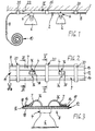
- Fig. 1
- 1 shows a side view of a light rail system according to the invention, which is mounted on a ceiling surface as an example, with a support profile, mounting elements, lampholders and luminaires arranged in these,
- Fig. 2
- a plan view of the support profile in the direction of arrow II of FIG. 1st
- Fig. 3
- 3 shows an enlarged cross section through the carrier profile along the section line III-III in FIG. 2,
- Fig. 4
- an embodiment of an exemplary light rail system mounted on a wall and a ceiling surface, showing a connection element and a connector element.
- Fig. 5
- 3 shows an enlarged cross section through a possible embodiment of a mounting element along the section line VV in FIG. 2,
- Fig. 6
- 5 shows a view as in FIG. 5 in an advantageous development of the mounting element,
- Fig. 7
- FIG. 8 shows a cross section through the support profile according to the invention along the section line VII-VII in FIG. 8, showing an advantageous embodiment of a lamp holder,
- Fig. 8
- 7 shows a plan view in the direction of arrow VIII according to FIG. 7,
- Fig. 9
- 2 shows a cross section through a further embodiment of the support profile according to the invention with an advantageous embodiment of a plug-in luminaire holder,
- Fig. 10
- 9 shows a cross section through the carrier profile according to FIG. 9 in the region of a mounting element,
- Fig. 11
- 3 shows a cross section through a further possible embodiment of the carrier profile,
- Fig. 12
- 4 shows a view of the light rail system mounted on the ceiling surface in the direction of arrow XII according to FIG. 4,
- Fig. 13
- 2 shows a cross section through a further embodiment of the support profile according to the invention, with a light holder shown,
- 14 and 15
- 13 also in "cross-sectional representations",
- Fig. 16
- a cross section through the carrier profile of FIG. 15 with an additional cover profile and
- Fig. 17
- a cross section through a support profile with a movable and drivable lamp holder in the longitudinal direction of the profile.
In den verschiedenen Figuren der Zeichnung sind gleiche Teile stets mit den gleichen Bezugszeichen bezeichnet.In the different figures of the drawing, the same parts are always designated with the same reference numerals.
Bestandteile des erfindungsgemäßen Lichtschienen-Systems sind gemäß Fig. 1 zumindest eine Leiterschiene 2 und mindestens eine Leuchtenfassung 4 für Leuchten 6, wobei - wie dargestellt - insbesondere Niedervolt-Reflektorleuchten eingesetzt werden können. Die Leiterschiene 2 besitzt mindestens zwei Stromleiter 7, es liegt jedoch im Rahmen der Erfindung, das erfindungsgemäße System als "Mehrleitersystem" beispielsweise mit drei Leitern 7 für Serienschaltungen und dergleichen auszubilden (vgl. Fig. 9 und 10).According to FIG. 1, components of the light rail system according to the invention are at least one
Die Leiterschiene 2 besteht nun erfindungsgemäß aus einem flexiblen, plastisch verformbaren, selbsttragenden Trägerprofil 8, weiches zudem vorteilhafterweise thermisch stabil ist, d.h. auch bei Erwärmung, die insbesondere durch die Leuchten 6 hervorgerufen wird, eine hinreichende mechanische Stabilität behält. Wie in Fig. 1 angedeutet, kann das erfindungsgemäße Trägerprofil 8 vorteilhafterweise nach seiner Herstellung als "Meterware"zu Rollen 10 aufgerollt und zur Montage wieder abgerollt sowie - wie in Fig. 2 angedeutet - mit einem Handwerkzeug (Schere, Blechschere, Seitenschneider) sehr einfach auf die gewünschte Länge geschnitten werden.According to the invention, the
Gemäß Fig. 2 besteht das Trägerprofil 8 in einer ersten Ausführungsform erfindungsgemäß aus einem flachen, streifenförmigen Leiterband 11, welches seinerseits vorzugsweise aus einem Trägerband 12 besteht, welches die oben genannten, mechanischen Eigenschaften des Trägerprofils 8 bewirkt, sowie aus - wie in Fig. 2 dargestellt - auf nur einer Oberfläche oder aber - gemäß Fig. 9 und 10 - auf beiden Oberflächen des Trägerbandes 12 angeordneten, die Stromleiter bildenden Leiterbahnen 14.According to FIG. 2, the
In einer in Fig. 3 dargestellten Ausführungsform der Erfindung besteht das Trägerband 12 aus einem Metallband 16, und zwar vorzugsweise aus einem Aluminiumband, wobei auf dem Metallband 16 vorzugsweise auf beiden Oberflächen jeweils eine Isolierschicht 18 angeordnet ist. In diesem Fall sind auf einer dieser Isolierschichten 18 die Leiterbahnen 14 angeordnet. Bei dieser vorteilhaften Ausführung des Trägerbandes 12 kann erfindungsgemäß das Metallband 16 als zusätzlicher Stromleiter verwendet werden. Hierzu kann das Metallband 16 mit Vorteil mittels die Isolierschicht 18 durchdringender Kontaktelemente kontaktiert werden (nicht dargestellt).In an embodiment of the invention shown in FIG. 3, the
In einer z.B. in Fig. 7 veranschaulichten, alternativen Ausführungsform des Leiterbandes 8 besteht das Trägerband 12 erfindungsgemäß einheitlich aus einem elektrisch isolierenden Material, insbesondere einem Kunststoff, wobei dieses Material dann die oben genannten mechanischen Eigenschaften aufweist. Alternativ können aber auch die Leiterbahnen 14 diese mechanischen Eigenschaften besitzen, wobei dann ein beliebiger Kunststoff für das Trägerband 12 verwendet werden kann.In a e.g. 7, alternative embodiment of the
Gemäß Fig. 1, 2 und 4 sind erfindungsgemäß mehrere in Längsrichtung des Leiterbandes 8 voneinander beabstandete Montageelemente 20 zum Befestigen des Trägerprofils 8 an Wand- und/oder Deckenflächen 22 vorgesehen. Diese Montageelemente 20 bilden folglich Abstandhaiter bzw. Befestigungssockel, wobei das Trägerprofil 8 vorzugsweise lösbar an den Montageelementen 20 befestigbar ist.1, 2 and 4, according to the invention, a plurality of mounting
Gemäß Fig. 5 und 6 können die Montageelemente 20 als "Montageclip" ausgebildet sein, die bei der Ausführung des Trägerprofils 8 als Leiterband 11 jeweils die Längsränder des Leiterbandes 11 seitlich umgreifende, vorzugsweise federelastische Haltearme 24 aufweisen. Hierbei ist das Trägerprofil 8 erfindungsgemäß über schnappbare Form- oder Kraftformschlußverbindungen mit den Montageelementen 20 verbindbar, indem es lediglich rastend zwischen die Haltearme 24 eingedrückt zu werden braucht. Alternativ oder zusätzlich zu dieser Verbindungsart kann das Trägerprofil 8 mit Vorteil auch stoffschlüssig mit den Montageelementen 20 verbunden werden, beispielsweise über gestrichelt eingezeichnete Klebestreifen 26, um ein Verrutschen des Trägerprofil 8 absolut auszuschließen.5 and 6, the mounting
In der Ausführungsform nach Fig. 5 sind die Montageelemente 20 unmittelbar beispielsweise über Schraubverbindungen 28 an der jeweiligen Wand- oder Deckenfläche 22 befestigt. In der in Fig. 6 dargestellten Alternative sind die Montageelemente 20 jeweils über ein Montageteil 30 mittelbar an der Fläche 22 befestigt, wobei in diesem Fall das Montageelement 20 mit dem Montageteil 30, welches einen Abstandhalter bildet, über eine Gelenkverbindung 32 schwenk- und/oder drehbeweglich verbunden ist. In Fig. 6 ist diese Schwenkbeweglichkeit durch die eingezeichneten Doppelpfeile 34 angedeutet. Diese gelenkige Lagerung des Montageteils 30 bewirkt eine Verstellmöglichkeit der Abstrahlrichtung der an dem Trägerprofil 8 gehalterten Leuchten 6.In the embodiment according to FIG. 5, the mounting
In einer nicht dargestellten Ausführungsform können die Montagelemente 20 mit Vorteil zugleich als Leuchtenfassungen ausgebildet sein, wobei die Montageelemente 20 dann jeweils die Stromleiter des Trägerprofils 8 mit Kontaktelementen der Leuchtenfassung elektrisch verbindende Anschlußelemente aufweisen.In an embodiment that is not shown, the mounting
In den dargestellten Ausführungsbeispielen sind die Leuchtenfassungen 4 jeweils in zwischen den Montageelementen 20 liegenden Bereichen des Trägerprofils 8 an diesem insbesondere kraft- und/oder formschlüssig gehaltert. Im Ausführungsbeispiel nach Fig. 3 sind hierzu die Leuchtenfassungen 4 auf der den Leiterbahnen 14 abgekehrten Seite des Leiterbandes 11 aufliegend angeordnet und durchgreifen jeweils mit elektrischen, vorzugsweise federelastischen Kontaktelementen 36 eine Durchgangsöffnung 38 des Leiterbandes 11 (siehe Fig. 2) und liegen auf der anderen Seite des Leiterbandes 11 zur Kontaktierung der Leiterbahnen 14 auf diesen auf. In einer nicht dargestellten Alternativausbildung können die Kontaktelemente 36 auch die Seitenränder des Leiterbandes 11 außen umgreifen und dann auf der anderen Seite des Leiterbandes 11 auf den Leiterbahnen 14 aufliegen. Die Öffnungen 38 des Leiterbandes 11 können bereits unmittelbar bei der Herstellung des Leiterbandes 11 vorgefertigt sein. Hierbei ist von besonderem Vorteil, daß stets anhand der Anzahl der vorhandenen Öffnungen 38 von unterschiedlich lang abgeschnittenen Stücken des Leiterbandes 11 festgestellt werden kann, welche Gesamt-Anschlußleistung jeweils vorliegt, da lediglich die Anschlußleistung einer Leuchte 6 mit der Anzahl der vorhandenen Öffnungen 38 multipliziert zu werden braucht.In the exemplary embodiments shown, the
In der Ausführungsform nach Fig. 7 und 8 bestehen die Leuchtenfassungen 4 mit Vorteil jeweils aus einem mit dem Trägerprofil 8 bzw. dem Leiterband 11 verbindbaren Kontaktteil 40 und einem die Leuchte 6 aufnehmenden Fassungsteil 42. Hierbei kann das Kontaktteil 40 im Bereich der Öffnung 38 des Leiterbandes 11 bajonettartig eingesetzt werden, d.h. das Kontaktteil 40 besitzt eine längliche, vorzugsweise rechteckige, der Öffnung 38 angepaßte Kontur, wodurch es in einer Stellung in einer zur Bandebene senkrechten Richtung (Pfeilrichtung 44 in Fig. 7) in die Öffnung 38 eingesetzt werden kann. Nachfolgend wird dann das Kontaktteil 40 in der Bandebene in Doppelpfeilrichtung 46 gemäß Fig. 8 verdreht, bis seine Kontaktelemente die Leiterbahnen 14 kontaktieren (siehe Fig. 7). Dabei kann mit besonderem Vorteil das Fassungsteil 42 über mindestens ein Gelenk 48 (Fig. 7) schwenk- und/oder drehbeweglich mit dem Kontaktteil 40 verbunden sein, um eine Einstellmöglichkeit für die Abstrahlrichtung der Leuchte 6 zu schaffen. Die Beweglichkeit der Leuchte 6 ist in Fig. 7 durch einen Doppelpfeil 50 veranschaulicht.In the embodiment according to FIGS. 7 and 8, the
Gemäß Fig. 4 ist weiterhin erfindungsgemäß mindestens ein Anschlußelement 52 vorgesehen, welches die Stromleiter 7 des Trägerprofils 8, d.h. die Leiterbahnen 14 und/oder das Metallband 16, mit Anschlüssen einer Spannungsquelle, insbesondere eines Transformators 54, z.B. über eine Leitungsverbindung 56 verbindet. Dieses Anschlußelement ist vorzugsweise als Steckelement mit einer Steck-Aufnahme zum Einstecken eines Endes des Trägerprofils 8 ausgebildet.According to FIG. 4, at least one
Ferner kann erfindungsgemäß mindestens ein Verbinderelement 58 zum Verbinden von zwei oder mehr Abschnitten des Trägerprofils 8 vorgesehen sein. Dieses Verbinderelement 58 besitzt für jeden zu verbindenden Abschnitt des Trägerprofils 8 vorzugsweise eine Steck-Aufnahme, wobei diese Steck-Aufnahmen in beliebigen Winkeln zueinander angeordnet sein können. In Fig. 4 ist ein Eckverbinder zur Verbindung zweier Trägerprofil-Abschnitte in einem Winkel von 90° dargestellt. Ebenso sind jedoch auch T-Verbinder oder Sternverbinder denkbar.Furthermore, according to the invention, at least one
In den Fig. 9 und 10 ist eine weitere Ausführungsform des erfindungsgemäßen Trägerprofils 8 dargestellt, welches wiederum als Leiterband 11 ausgebildet ist, jedoch besteht dieses Leiterband 11 aus einer mittigen Isolierschicht 18 mit beidseitig angeordneten Leiterbahnen 14. In diesem Ausführungsbeispiel sind auf einer Seite des Leiterbandes 11 eine Leiterbahn 14 und auf der anderen Seite zwei Leiterbahnen 14 angeordnet. In diesem Fall bewirken die Leiterbahnen 14 die oben beschriebenen, mechanischen Eigenschaften des erfindungsgemäßen Trägerprofil 8. Dieses Trägerprofil 8 eignet sich insbesondere für eine Montage bzw. Ausrichtung senkrecht zu einer Wand- oder Deckenfläche 22, wie dies in Fig. 10 dargestellt ist. Die Kontaktierung der Leiterbahnen 14 erfolgt dann mittels eines geeigneten Kontaktteils 40 jeweils von der Seite her. Wie in Fig. 9 dargestellt, ist es vorteilhaft, wenn das Kontaktteil 40 aus zwei Teilen 40a, 40b besteht, die über elektrische Steckverbinder 62 lösbar miteinander verbunden sind, was durch den in Fig. 9 eingezeichneten Doppelpfeil 64 veranschaulicht werden soll. Auch hier ist wiederum eine Schwenkbeweglichkeit des Fassungsteils 42 über in diesem Fall zwei Gelenke 48 gewährleistet. Das in Fig. 10 dargestellte für diese Ausführung des Trägerprofils 8 verwendete Montageelement 20 ist im wesentlichen U-förmig ausgebildet und umgreift das Trägerprofil 8 mit zwei Haltearmen 66 rastend bzw. klemmend. Auch dieses Montageelement 20 kann - wie dargestellt - unmittelbar oder aber alternativ hierzu mittelbar analog zu Fig. 6 an der Wand- oder Deckenfläche 22 befestigt werden.9 and 10 show a further embodiment of the
Im Ausführungsbeispiel nach Fig. 11 besteht das erfindungsgemäße Trägerprofil 8 aus einem band- oder streifenförmigen Trägerband 12 aus Isolationsmaterial, in welches in sandwichartiger Anordnung mehrere Leiterbahnen 14 parallel übereinander eingebettet sind. Diese Leiterbahnen 14 reichen dabei jeweils bis zu den Seitenrändern des Trägerprofils 8, so daß hier in dem Bereich der Seitenränder die Kontaktierung in der in Fig. 11 dargestellten Weise erfolgen kann.In the exemplary embodiment according to FIG. 11, the
In Fig. 12 ist beispielhaft dargestellt, wie variabel das erfindungsgemäße Lichtschienen-System montiert werden kann. Das erfindungsgemäße Trägerprofil 8 kann aufgrund seiner Flexibilität und seiner formstabilen Eigenschaften in beliebigem Verlauf verlegt werden. In Fig. 12 sind zwei sich kreuzende Stränge des Trägerprofils 8 dargestellt, wobei im Kreuzungspunkt ein sternförmiges Verbinderelement 58 mit vier Steckaufnahmen angeordnet ist. Hierbei ist es besonders vorteilhaft, wenn das Verbinderelement 58 elektrische Schaltmittel aufweist, über die die einzelnen Teilstränge des Trägerprofils 8 elektrisch verbunden oder getrennt werden können.FIG. 12 shows an example of how variably the light rail system according to the invention can be installed. The
In den vorteilhaften Ausführungsbeispielen nach Fig. 13 bis 17 besteht das Trägerprofil 8 erfindungsgemäß aus einem aus Isolationsmaterial bestehenden Profilkörper 70, wobei dieser Profilkörper 70 vorzugsweise für jeden Stromleiter 7 eine randoffene, im Querschnitt insbesondere etwa Ω-förmige Leiternut 72 aufweist, in der der jeweilige Stromleiter 7 insbesondere formschlüssig sowie versenkt gehalten ist. Hierbei sind die Stromleiter 7 vorzugsweise als Drähte, insbesondere als Kupferdrähte mit kreisförmigem Querschnitt, ausgebildet. In diesem Fall kann das Trägerprofil 8 seine erfindungsgemäßen mechanischen Eigenschaften durch die entsprechenden Eigenschaften der Stromleiter 7 erhalten. Besonders vorteilhaft ist es jedoch, wenn - wie dargestellt - der Profilkörper 70 ein in Profillängsrichtung verlaufendes, flexibles, selbsttragendes, plastisch verformbares Tragelement 74 aufweist. Dieses Tragelement 74 ist vorzugsweise als Seele in den Kunststoff-Profilkörper 70 eingebettet. In den dargestellten Ausführungsbeispielen besitzt das Tragelement 74 jeweils einen kreisförmigen Querschnitt. Es kann aus Metall, insbesondere Aluminium, bestehen.In the advantageous exemplary embodiments according to FIGS. 13 to 17, the
In einer Weiterbildung dieser erfindungsgemäßen Ausführungsform weist der Profilkörper 70 zusätzlich zu den Leiternuten 72 weitere randoffene Aufnahmenuten 76 zur vorzugsweise ebenfalls formschlüssigen und versenkten Aufnahme von Zusatzleitern 78 auf. Diese Zusatzleiter 78 können für beliebige Funktionen verwendet werden, wie beispielsweise als Lautsprecherleitungen, Steuerleitungen oder dergleichen.In a development of this embodiment according to the invention, the
Die Anordnung der Stromleiter 7 und der Zusatzleiter 78 ist grundsätzlich beliebig. In den dargestellten Ausführungsbeispielen ist der Profilkörper 70 jeweils mit im wesentlichen rechteckigem Querschnitt ausgebildet, wobei gemäß Fig. 13, 15, 16 und 17 die Stromleiter 7 und/oder die Zusatzleiter 78 im Bereich einer Oberfläche des Profilkörpers 70 angeordnet sind. Im Beispiel nach Fig. 14 ist jeweils ein Stromleiter 7 auf diametral gegenüberliegenden Seitenflächen des Profilkörpers 70 angeordnet, während die Zusatzleiter 78 auf einer der diese beiden gegenüberliegenden Seiten verbindenden Flächen des Profilkörpers 70 angeordnet sind.The arrangement of the
Zur Kontaktierung der Stromleiter 7 und/oder der Zusatzleiter 78 besitzen die Leuchtenfassungen 4 bzw. deren Kontaktteile 40 jeweils Kontaktelemente 80, die erfindungsgemäß in die Leiternuten 72 und/oder die Aufnahmenuten 76 des Profilkörpers 70 derart eingreifen, daß sie die dort angeordneten Leiter 7, 78 kontaktieren. Dabei können die Öffnungen der Leiternuten 72 und der Aufnahmenuten 76 vorteilhafterweise derart schmal sein, daß Berührungen der spannungsführenden Leiter ausgeschlossen sind.For contacting the
Im Ausführungsbeispiel nach Fig. 16 ist erfindungsgemäß ein mit dem Trägerprofil 8 kraft- und/oder formschlüssig und/oder stoffschlüssig verbindbares Abdeckprofil 82 vorgesehen, welches die Leiternuten 72 und/oder die Aufnahmenuten 76 vorzugsweise wasserdicht verschließt. Diese Ausführung ist insbesondere für die Außenmontage besonders vorteilhaft, da hierdurch die Stromleiter 7 und/oder die Zusatzleiter 78 vor Feuchtigkeit und Nässe geschützt sind.In the exemplary embodiment according to FIG. 16, according to the invention, a
In einer in Fig. 17 dargestellten, vorteilhaften Weiterbildung der Erfindung sind die Leuchtenfassungen 4 an dem Trägerprofil 8 bzw. dem Profilkörper 70 in Profillängsrichtung verschiebbar sowie vorzugsweise motorisch antreibbar geführt. Hierzu besitzt die Leuchtenfassung 4 bzw. das Kontaktteil 40 eine drehbar gelagerte Welle 84, die über einen motorischen Antrieb 86 antreibbar ist und anderseitig ein Zahnrad 88 trägt, weiches in eine Zahnstangen-Verzahnung 90 des Trägerprofils 8 bzw. des Profilkörpers 70 eingreift. Die Ansteuerung des motorischen Antriebes 86 kann hierbei über die in Fig. 17 nicht dargestellten Zusatzleiter 78 erfolgen. Die Kontaktelemente 80 sind dabei als Schleifkontakte ausgebildet, so daß auch während der Verschiebebewegung die Leiter 7 und 78 gut kontaktiert werden. Diese Ausführungsform eignet sich insbesondere für Effektbeleuchtungen beispielsweise in Diskotheken und dergleichen.In an advantageous development of the invention shown in FIG. 17, the
Die Erfindung ist nicht auf die dargestellten und beschriebenen Ausführungsbeispiele beschränkt, sondern umfaßt auch alle im Sinne der Erfindung gleichwirkenden Ausführungen.The invention is not limited to the exemplary embodiments shown and described, but also encompasses all embodiments having the same effect in the sense of the invention.
Claims (20)
- Lighting bus bar system with a conductor rail (2) having at least two current conductors (7) and with at least one luminaire socket (4) connectable to the conductor rail (2) while contacting the current conductor (7), in particular for low voltage luminaires, characterized in that the conductor rail (2) consists of a girder profile (8) which is firstly flexible in design in such a way that it can be rolled up, which is secondly plastically deformable in such a way that it can be mounted with virtually any directional course and which thirdly has self-supporting properties in such a way that it has sufficient stability in the region between each two mounting elements (20) provided for wall or ceiling mounting and spaced from one another in the longitudinal direction of the profile that fastening of at least one luminaire socket (4) is possible in this region without significant changes of shape owing to the weight of the luminaire socket (4).
- Lighting bus bar system according to claim 1, characterized in that the girder profile (8) is designed as a flat band-shaped conductor strip (11) and preferably consists of a girder strip (12) with conductor tracks (14) arranged on one side or on both sides of the girder strip (12) or embedded in the girder strip (12) and forming the current conductors (7).
- Lighting bus bar system according to claim 2, characterized in that the girder strip (12) consists of a metal strip (16), in particular an aluminium strip, with insulating layers (18) preferably arranged on either side or of an electrically insulating material, in particular plastics material.
- Lighting bus bar system according to claim 3, characterized in that the metal strip (16) of the girder strip (12) forms a current conductor to be contacted, in particular, by means of contact elements which penetrate the insulating layer (18).
- Lighting bus bar system according to claim 1, characterized in that the girder profile (8) consists of a three-dimensional profile member (70) made of insulating material and is preferably provided with conductor grooves (72) which are open at the edges and receive the current conductors (7) in particular positively and in a countersunk manner.
- Lighting bus bar system according to claim 5, characterized in that the profile member (70) possesses a carrying element (74) which extends in the longitudinal direction of the profile, has said properties - flexibility, plastic deformability and self-supporting capacity -, is preferably embedded as a core in the plastics material profile member (70) and consists, in particular, of metal, preferably aluminium.
- Lighting bus bar system according to claim 5 or 6, characterized in that the profile member (70) has, in addition to the conductor grooves (72), further holding grooves (76) which are open at the edges for the preferably positive holding of additional conductors (78).
- Lighting bus bar system according to one or more of claims 5 to 7, characterized by a covering profile (82) which can be non-positively and/or positively and/or integrally connected to the girder profile (8) and preferably seals the conductor grooves (72) and/or the holding grooves (76) in a water-tight manner.
- Lighting bus bar system according to one or more of claims 1 to 8, characterized in that the girder profile (8) can be connected to the mounting elements (20) by means of, in particular, positive or non-positive snap fasteners and/or integrally.
- Lighting bus bar system according to one or more of claims 1 to 9, characterized in that the mounting elements (20) can be fastened directly or in each case via a mounting member (30) directly on a wall or ceiling surface (22), the respective mounting element (20) preferably being connected pivotally and/or rotatably to the mounting member (30) via an articulated joint (32).
- Lighting bus bar system according to one or more of claims 1 to 10, characterized in that the mounting elements (20) are simultaneously designed as luminaire sockets, the mounting elements (20) having respective attachment elements which electrically connect the current conductors of the girder profile (8) to contact elements of the luminaire socket (4).
- Lighting bus bar system according to one or more of claims 1 to 11, characterized in that the luminaire sockets (4) are held non-positively and/or positively on the respective girder profile (8), preferably via positive or non-positive snap fasteners.
- Lighting bus bar system according to claim 12, characterized in that the luminaire sockets (4) are arranged on one side of the girder profile designed as a conductor strip (11) and, in each case with electrical, preferably resilient contact elements (36), penetrate an orifice (38) in the conductor strip (11) or externally surround its lateral edges and, on the other side of the conductor strip (11), the conductor tracks (14) rest with contact thereon.
- Lighting bus bar system according to claim 12, characterized in that the luminaire sockets (4) with contact elements (80) engage in the conductor grooves (72) and/or the holding grooves (76) of the girder profile (8) designed as a profile member (70) and contact the current conductors (7) and/or the additional conductors (78).
- Lighting bus bar system according to one or more of claims 1 to 14, characterized in that the luminaire sockets (4) each consist of a contact member (40) connectable to the girder profile (8) and a socket member (42) holding the luminaire (6), the socket member (42) preferably being pivotally and/or rotatably connected to the contact member (40) by at least one joint (48).
- Lighting bus bar system according to claim 15, characterized in that the contact member (40) in two parts consists of two members (40a, 40b) detachably connected via electric plug-in connectors (62), one member (40a) being connectable to the girder profile (8) and the other member (40b) to the socket member (42).
- Lighting bus bar system according to one or more of claims 1 to 16, characterized by at least one terminal element (52) connecting the current conductors (7) of the girder profile (8) to terminals of a voltage source, in particular a transformer (54).
- Lighting bus bar system according to one or more of claims 1 to 17, characterized by at least one connector element (58) for the mechanical and/or electrical connection of two or more portions or the girder profile (8) in an arrangement preferably angled to one another.
- Lighting bus bar system according to claim 17 and/or 18, characterized in that the terminal element (52) and/or the connector element (58) have/has switching means for producing and releasing the electrical connections between the voltage source and the current conductors (7) and/or between the current conductors (7) of the individual portions of the girder profile (8).
- Lighting bus bar system according to one or more of claims 1 to 19, characterized in that the luminaire sockets (4) are guided on the girder profile (8) so as to be displaceable in the longitudinal direction of the profile and are preferably guided so as to be drivable by a motor.
Priority Applications (3)
| Application Number | Priority Date | Filing Date | Title |
|---|---|---|---|
| ES89111772T ES2094116T3 (en) | 1989-06-28 | 1989-06-28 | LIGHT FLOORING SYSTEM. |
| EP19890111772 EP0404979B1 (en) | 1989-06-28 | 1989-06-28 | Light rail system |
| DE58909735T DE58909735D1 (en) | 1989-06-28 | 1989-06-28 | Light rail system |
Applications Claiming Priority (1)
| Application Number | Priority Date | Filing Date | Title |
|---|---|---|---|
| EP19890111772 EP0404979B1 (en) | 1989-06-28 | 1989-06-28 | Light rail system |
Publications (2)
| Publication Number | Publication Date |
|---|---|
| EP0404979A1 EP0404979A1 (en) | 1991-01-02 |
| EP0404979B1 true EP0404979B1 (en) | 1996-09-18 |
Family
ID=8201546
Family Applications (1)
| Application Number | Title | Priority Date | Filing Date |
|---|---|---|---|
| EP19890111772 Expired - Lifetime EP0404979B1 (en) | 1989-06-28 | 1989-06-28 | Light rail system |
Country Status (3)
| Country | Link |
|---|---|
| EP (1) | EP0404979B1 (en) |
| DE (1) | DE58909735D1 (en) |
| ES (1) | ES2094116T3 (en) |
Cited By (3)
| Publication number | Priority date | Publication date | Assignee | Title |
|---|---|---|---|---|
| US9303854B2 (en) | 2013-03-12 | 2016-04-05 | Apex Technologies, Inc. | Electrical rail systems with axially interleaved contact arrays |
| US10132452B2 (en) | 2013-03-14 | 2018-11-20 | Apex Technologies, Inc. | Suspended track and planar electrode systems and methods |
| US10680383B2 (en) | 2013-03-14 | 2020-06-09 | Apex Technologies, Inc. | Linear electrode systems for module attachment with non-uniform axial spacing |
Families Citing this family (11)
| Publication number | Priority date | Publication date | Assignee | Title |
|---|---|---|---|---|
| DE19510507C2 (en) * | 1995-03-23 | 1999-11-18 | Alulite Lichtsysteme Gmbh | Electric lighting system |
| DE29600747U1 (en) * | 1996-01-17 | 1996-03-07 | Wonnemann Andreas | fairy lights |
| EP0822625A3 (en) * | 1996-04-22 | 1998-12-09 | Holtkötter Leuchten GmbH | 12 Volt rail system where a light source can be connected at any point |
| BE1010401A3 (en) * | 1996-07-02 | 1998-07-07 | Gieraerts Eddy Jozef Ghislain | Fitting |
| BE1010396A3 (en) * | 1996-07-02 | 1998-07-07 | Gieraerts Eddy Jozef Ghislain | Light-fitting |
| DE19745048C2 (en) * | 1997-10-11 | 2001-04-12 | Verbeek Leuchten Gmbh | Power distribution and purchase system |
| DE29905052U1 (en) | 1999-03-19 | 1999-06-02 | Dornier Gmbh Lindauer | Device for operating weaving machines |
| DE10226761A1 (en) * | 2002-06-14 | 2004-01-08 | Patent-Treuhand-Gesellschaft für elektrische Glühlampen mbH | Bayonet base for lamp holder |
| DE20314831U1 (en) * | 2003-09-23 | 2004-02-26 | Bruck, Jochen | Busbar arrangement for low-voltage lamps and light-emitting diodes |
| DE202005005567U1 (en) * | 2005-04-07 | 2006-08-17 | Paulmann Licht Gmbh | Holding device for a light |
| DE102005016512A1 (en) * | 2005-04-11 | 2006-10-12 | Ingo Maurer Gmbh | lighting system |
Family Cites Families (2)
| Publication number | Priority date | Publication date | Assignee | Title |
|---|---|---|---|---|
| GB2150766B (en) * | 1983-05-17 | 1987-11-18 | Tulla Lighting Limited | Track lighting |
| FR2623030A1 (en) * | 1987-11-09 | 1989-05-12 | Lepaillier Patrick | Device for electrical supply of a support for fixing electrical and/or electronic equipment to a rail |
-
1989
- 1989-06-28 ES ES89111772T patent/ES2094116T3/en not_active Expired - Lifetime
- 1989-06-28 EP EP19890111772 patent/EP0404979B1/en not_active Expired - Lifetime
- 1989-06-28 DE DE58909735T patent/DE58909735D1/en not_active Expired - Fee Related
Cited By (3)
| Publication number | Priority date | Publication date | Assignee | Title |
|---|---|---|---|---|
| US9303854B2 (en) | 2013-03-12 | 2016-04-05 | Apex Technologies, Inc. | Electrical rail systems with axially interleaved contact arrays |
| US10132452B2 (en) | 2013-03-14 | 2018-11-20 | Apex Technologies, Inc. | Suspended track and planar electrode systems and methods |
| US10680383B2 (en) | 2013-03-14 | 2020-06-09 | Apex Technologies, Inc. | Linear electrode systems for module attachment with non-uniform axial spacing |
Also Published As
| Publication number | Publication date |
|---|---|
| EP0404979A1 (en) | 1991-01-02 |
| ES2094116T3 (en) | 1997-01-16 |
| DE58909735D1 (en) | 1996-10-24 |
Similar Documents
| Publication | Publication Date | Title |
|---|---|---|
| DE10025648B4 (en) | Busbar system | |
| EP1141624B1 (en) | Light-band system and method for mounting a light-band system | |
| EP2026425B1 (en) | Electricity rail system | |
| EP0404979B1 (en) | Light rail system | |
| DE7809825U1 (en) | Coupling piece | |
| DE19849101A1 (en) | Busbar system, especially for lighting devices | |
| CH663291A5 (en) | POWER RAIL WITH POWER TAKING DEVICE. | |
| EP1284035B1 (en) | Supply track system | |
| EP0307396B1 (en) | Lamp | |
| DE2243686A1 (en) | ELECTRIC POWER BAR ARRANGEMENT WITH CONNECTION BOX SYSTEM | |
| AT408162B (en) | ADAPTER, BUSBAR AND COUPLING DEVICE | |
| EP0795216A1 (en) | Current supply device for low voltage equipment | |
| DE3245384A1 (en) | Electrical busbar for power supply, and associated connecting device | |
| DE4032622C2 (en) | ||
| DE3817133C2 (en) | ||
| EP2867961B1 (en) | Channel system | |
| DE19652401C2 (en) | Busbar system | |
| DE10216250B4 (en) | End piece for a busbar of a busbar system | |
| EP1841013A1 (en) | Illumination device | |
| DE19750100C2 (en) | connecting device | |
| DE3919201A1 (en) | Bus=bar for LV lighting in large rooms - is made from rectangular bars and has light attached by simple adaptor | |
| DE3007970A1 (en) | ELECTRICAL SWITCHGEAR | |
| DE2538199A1 (en) | T-Junction screw terminal for insulated through wire - has open slot and pointed screw for through wire | |
| DE3806241A1 (en) | Installation device for low-voltage luminaires | |
| DE102012107907A1 (en) | Lamp module for fluorescent lamp, has socket or cover portion with fastening unit, by which socket and cover portion are detachably mounted on base rail, where socket has two dividing contacts that penetrate socket attached to base rail |
Legal Events
| Date | Code | Title | Description |
|---|---|---|---|
| PUAI | Public reference made under article 153(3) epc to a published international application that has entered the european phase |
Free format text: ORIGINAL CODE: 0009012 |
|
| 17P | Request for examination filed |
Effective date: 19891108 |
|
| AK | Designated contracting states |
Kind code of ref document: A1 Designated state(s): DE ES FR GB IT NL SE |
|
| 17Q | First examination report despatched |
Effective date: 19930317 |
|
| GRAH | Despatch of communication of intention to grant a patent |
Free format text: ORIGINAL CODE: EPIDOS IGRA |
|
| GRAH | Despatch of communication of intention to grant a patent |
Free format text: ORIGINAL CODE: EPIDOS IGRA |
|
| GRAA | (expected) grant |
Free format text: ORIGINAL CODE: 0009210 |
|
| AK | Designated contracting states |
Kind code of ref document: B1 Designated state(s): DE ES FR GB IT NL SE |
|
| PG25 | Lapsed in a contracting state [announced via postgrant information from national office to epo] |
Ref country code: GB Effective date: 19960918 |
|
| REF | Corresponds to: |
Ref document number: 58909735 Country of ref document: DE Date of ref document: 19961024 |
|
| ITF | It: translation for a ep patent filed |
Owner name: ING. A. GIAMBROCONO & C. S.R.L. |
|
| PG25 | Lapsed in a contracting state [announced via postgrant information from national office to epo] |
Ref country code: SE Effective date: 19961218 |
|
| ET | Fr: translation filed | ||
| REG | Reference to a national code |
Ref country code: ES Ref legal event code: FG2A Ref document number: 2094116 Country of ref document: ES Kind code of ref document: T3 |
|
| GBV | Gb: ep patent (uk) treated as always having been void in accordance with gb section 77(7)/1977 [no translation filed] |
Effective date: 19960918 |
|
| PLBE | No opposition filed within time limit |
Free format text: ORIGINAL CODE: 0009261 |
|
| STAA | Information on the status of an ep patent application or granted ep patent |
Free format text: STATUS: NO OPPOSITION FILED WITHIN TIME LIMIT |
|
| 26N | No opposition filed | ||
| PGFP | Annual fee paid to national office [announced via postgrant information from national office to epo] |
Ref country code: FR Payment date: 20010411 Year of fee payment: 13 |
|
| PGFP | Annual fee paid to national office [announced via postgrant information from national office to epo] |
Ref country code: ES Payment date: 20010605 Year of fee payment: 13 |
|
| PGFP | Annual fee paid to national office [announced via postgrant information from national office to epo] |
Ref country code: NL Payment date: 20010630 Year of fee payment: 13 |
|
| PGFP | Annual fee paid to national office [announced via postgrant information from national office to epo] |
Ref country code: DE Payment date: 20010813 Year of fee payment: 13 |
|
| PG25 | Lapsed in a contracting state [announced via postgrant information from national office to epo] |
Ref country code: ES Free format text: LAPSE BECAUSE OF NON-PAYMENT OF DUE FEES Effective date: 20020629 |
|
| PG25 | Lapsed in a contracting state [announced via postgrant information from national office to epo] |
Ref country code: NL Free format text: LAPSE BECAUSE OF NON-PAYMENT OF DUE FEES Effective date: 20030101 Ref country code: DE Free format text: LAPSE BECAUSE OF NON-PAYMENT OF DUE FEES Effective date: 20030101 |
|
| PG25 | Lapsed in a contracting state [announced via postgrant information from national office to epo] |
Ref country code: FR Free format text: LAPSE BECAUSE OF NON-PAYMENT OF DUE FEES Effective date: 20030228 |
|
| NLV4 | Nl: lapsed or anulled due to non-payment of the annual fee |
Effective date: 20030101 |
|
| REG | Reference to a national code |
Ref country code: FR Ref legal event code: ST |
|
| REG | Reference to a national code |
Ref country code: ES Ref legal event code: FD2A Effective date: 20030711 |
|
| PG25 | Lapsed in a contracting state [announced via postgrant information from national office to epo] |
Ref country code: IT Free format text: LAPSE BECAUSE OF NON-PAYMENT OF DUE FEES;WARNING: LAPSES OF ITALIAN PATENTS WITH EFFECTIVE DATE BEFORE 2007 MAY HAVE OCCURRED AT ANY TIME BEFORE 2007. THE CORRECT EFFECTIVE DATE MAY BE DIFFERENT FROM THE ONE RECORDED. Effective date: 20050628 |