EP1284035B1 - Systeme de rails conducteurs - Google Patents
Systeme de rails conducteurs Download PDFInfo
- Publication number
- EP1284035B1 EP1284035B1 EP01923633A EP01923633A EP1284035B1 EP 1284035 B1 EP1284035 B1 EP 1284035B1 EP 01923633 A EP01923633 A EP 01923633A EP 01923633 A EP01923633 A EP 01923633A EP 1284035 B1 EP1284035 B1 EP 1284035B1
- Authority
- EP
- European Patent Office
- Prior art keywords
- carrier
- current
- elements
- rail
- wire
- Prior art date
- Legal status (The legal status is an assumption and is not a legal conclusion. Google has not performed a legal analysis and makes no representation as to the accuracy of the status listed.)
- Expired - Lifetime
Links
Images


Classifications
-
- H—ELECTRICITY
- H01—ELECTRIC ELEMENTS
- H01R—ELECTRICALLY-CONDUCTIVE CONNECTIONS; STRUCTURAL ASSOCIATIONS OF A PLURALITY OF MUTUALLY-INSULATED ELECTRICAL CONNECTING ELEMENTS; COUPLING DEVICES; CURRENT COLLECTORS
- H01R25/00—Coupling parts adapted for simultaneous co-operation with two or more identical counterparts, e.g. for distributing energy to two or more circuits
- H01R25/14—Rails or bus-bars constructed so that the counterparts can be connected thereto at any point along their length
-
- F—MECHANICAL ENGINEERING; LIGHTING; HEATING; WEAPONS; BLASTING
- F21—LIGHTING
- F21S—NON-PORTABLE LIGHTING DEVICES; SYSTEMS THEREOF; VEHICLE LIGHTING DEVICES SPECIALLY ADAPTED FOR VEHICLE EXTERIORS
- F21S4/00—Lighting devices or systems using a string or strip of light sources
- F21S4/20—Lighting devices or systems using a string or strip of light sources with light sources held by or within elongate supports
- F21S4/28—Lighting devices or systems using a string or strip of light sources with light sources held by or within elongate supports rigid, e.g. LED bars
-
- F—MECHANICAL ENGINEERING; LIGHTING; HEATING; WEAPONS; BLASTING
- F21—LIGHTING
- F21V—FUNCTIONAL FEATURES OR DETAILS OF LIGHTING DEVICES OR SYSTEMS THEREOF; STRUCTURAL COMBINATIONS OF LIGHTING DEVICES WITH OTHER ARTICLES, NOT OTHERWISE PROVIDED FOR
- F21V21/00—Supporting, suspending, or attaching arrangements for lighting devices; Hand grips
- F21V21/34—Supporting elements displaceable along a guiding element
- F21V21/35—Supporting elements displaceable along a guiding element with direct electrical contact between the supporting element and electric conductors running along the guiding element
Definitions
- the present invention relates to a busbar system for lamps according to the preamble of claim 1 and a wire support member.
- busbar systems and wire support elements are known from US-A-3,831,130.
- Conductor rail systems or strip lights are used in a variety of forms, as they offer a high degree of flexibility in the individual planning of lighting structures for specific requirements compared to fixed or built-in luminaires.
- the busbar systems consist of several individual elements, which are assembled according to the modular principle, so that the entire arrangement can be adapted to the premises to be illuminated.
- the basic structure of a busbar system is formed by mounting rails, which are assembled to the desired structure and serve to hold the power supply and control lines and the individual lights.
- the mounting rails must therefore have a high stability and are usually made of metal. They may have different shapes, for example, DIN rails with a Y-profile or an A-profile are known. However, the most widespread are U-shaped mounting rails, which with their middle leg on a support, e.g. a room ceiling or room wall are attached.
- the individual lighting modules are attached, usually the length of a single mounting rail is a multiple of the length of the lighting modules. For example, mounting rails with a length of 3 m or 4.50 m are offered if the luminaire modules have a length of 1.50.
- Such integer aspect ratios are chosen to simplify planning in designing a lighting system.
- corresponding lines run on or within the mounting rails.
- other lines for the transmission of control signals can be provided in addition to the lines for power supply, which opens up the possibility of individually controlling and dimming the individual lights when using a suitable control system.
- the lines run in the form of a through-wiring within the U-shaped mounting rails, wherein in regular Distances that correspond to the length of the luminaire modules, Abgriffbuchsen are arranged.
- the Abgriffbuchsen be clamped in the mounting rails, with undercuts engage behind corresponding projections of the mounting rails.
- the luminaire modules can be mounted at the points specified by the tapping bushes by placing and fastening them on the support rails that are open at the bottom.
- the contacting of the lines via a located on the lamp modules contacting element which has terminal contacts which engage when placing the lamp module on the mounting rail in openings of the pick-up bushing while contact with the corresponding wires in contact. Furthermore, the lighting modules on rotary knobs, which are rotated after placement, thereby ensuring a mechanical attachment to the mounting rails.
- the luminaire modules can each be arranged only at the locations that are predetermined by the Abgriffbuchsen, otherwise no electrical contact is possible.
- busbar systems were developed which have a Stromleitprofil held by the support rails.
- This Stromleitprofil consists of elongated bodies of non-conductive material - usually plastic - extending in the longitudinal direction of the support rails and accessible from a contacting side grooves for receiving wires for the power supply and / or transmission of control signals.
- a luminaire can be disposed at any position within that range, so that there is greater freedom in planning and realization of the lighting system ,
- the length of a single Stromleitprofil body is tuned to the length of the mounting rail. Since support rails are offered in different lengths, it is thus necessary to offer Stromleitprofil body in the appropriate sizes, whereby the total cost of the busbar system can be increased, since a large number of parts must be provided. In addition, it is necessary when assembling two mounting rails to connect the two Stromleitprofile also together. This compound is problematic in that it must be ensured in this area that no accidental contact of a wire is possible. A corresponding standard requires that a 1mm-thick test wire in straight-line stretch can not hit one of the wires. The connection therefore takes place with the help of a so-called row connector, which, however, itself offers no possibility of contacting, which has the consequence that within the connection area between two support rails still no contacting possible.
- the Stromleitprofil forming plastic body are produced by extrusion. This method is disadvantageous in that it allows plastic parts to be manufactured only with limited precision, since the plastic cools very quickly after leaving the extrusion die and changes its shape. This has the consequence that one-piece Stromleitprofil body can be made only to a certain complexity.
- the object is achieved by a busbar system, which has the features of claim 1, or by a wire-holding element according to claim 14.
- the busbar system is characterized in that the Stromleitprofil held by a single support rail consists of at least two adjoining wire support elements made of non-conductive material, which have the grooves for receiving the wires.
- the wire support elements are in their end regions formed such that they overlap overlapping with each other when joining with projections located at their ends so that they form the grooves in the connection region between two wire-holding elements and open to the contacting side channels. These channels are accessible only from the contacting side, but otherwise as well as the grooves of the wire support elements enclosed, so that the aforementioned safety standard is met in these areas.
- a continuous but secure contacting possibility is created over the entire length of a mounting rail away.
- the Stromleitprofils of several individual wire holder elements Due to the modular joining of the Stromleitprofils of several individual wire holder elements, it is possible to offer mounting rails of different lengths, to use them with a Stromleitprofil only wire holder elements of a single length, since the Stromleitprofil only by changing the number of wire holder elements to the length of the mounting rail can be adapted. This results in a significantly lower production cost. Furthermore, no elongated and expensive be created to be produced one-piece plastic parts.
- the wire-holding elements can be produced, for example, by means of the much easier-to-control and less expensive injection molding process.
- the wire holder elements arranged one behind the other at a greater length have an expansion clearance, whereby it is still ensured that there is a possibility of contacting over the connection region and nevertheless contact protection is provided.
- the wire support elements have at their ends locking elements which engage in the assembly of two wire-holding elements and limit a mutual displacement or distance in the longitudinal direction to a predetermined movement play.
- the wire-retaining elements cool and contract, they move away to a predetermined maximum distance, which still provides protection against contact; when heated, they approach each other.
- a continuous Stromleitprofil is formed independently of temperature.
- the wire support members have a length of about 500 mm, wherein the allowed game, with which two adjacent wire support members can move against each other, about 8 mm, which is sufficient for the temperature differences usually occurring in the busbar system.
- the locking elements also have the advantage that the wire support members can be hung together to form a rail, which can be inserted as a whole in the mounting rail, whereby the assembly is facilitated.
- the wire support members on guide arms which engage in corresponding guide grooves which are provided on or in the support rail, so that the wire support members are securely stored.
- the mounting rails may have, for example, an A-profile, a Y-profile or a U-profile, wherein the wire support members are arranged according to the profile on the outside of the support rail or within thereof.
- the wire support members consist of two side wings, which have the grooves for receiving the wires and are to be arranged on the side walls, these side wings are connected to each other at regular intervals via connecting webs. These connecting webs are arranged on the middle leg of the wire rail.
- one of the two side wings may have a parallel to the center leg of the support rail arranged horizontal leg, which forms together with protruding from the connecting webs retaining legs over the length of the support rail away an additional hollow or receiving space, which are used for receiving additional cables or lines can.
- the inventive concept of a modular Stromleitprofils of a plurality of juxtaposed wire support elements provides the ability to realize over an arbitrary length across a continuous contacting possibility by the Stromleitprofil is used after the merger of the support rails in this.
- the DIN rails are usually already assembled ready, i. sold with an already inserted Stromleitprofil with the wires arranged therein. This is because it is easier when creating a trunking system to assemble the already assembled mounting rails, as first add together empty mounting rails and then use the Stromleitprofile.
- a further development of the invention therefore relates to a connecting element which also forms a contacting possibility at these interfaces.
- the connecting element of the contacting side and the two end faces accessible groove-shaped recesses corresponding to the grooves of the Stromleitprofile, wherein in the recesses in each case a metal connector is used, to which the wires to be joined together from both sides can be connected.
- This also consists of a non-conductive material connecting element closes the gap between the Stromleitprofilen two mounting rails and ensures that over the entire length of the busbar system away a luminaire module attached and to the lines of the Busbar system can be connected, since the metal connectors in the transition region form the contact surfaces for the terminal contacts of the lamp module.
- the metal connectors preferably have an elongated contacting plate and U-shaped spring elements arranged at both ends thereof, by means of which the wires are clamped during insertion and pressed against the contacting plate. At the same time, it is ensured by the spring elements that the wires can not move in a pump-like manner during thermal expansion of the wire-holding elements and possibly even emigrate.
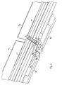
- U-shaped mounting rails in which Stromleitprofile are arranged on both side walls, a mechanical connection of two adjacent mounting rails preferably by means of a short U-shaped connecting rail, which engages half in both mounting rails and at the side legs, the connecting elements are arranged.
- the luminaire module has a contacting element with a plurality of terminal contacts, wherein the contacting element from the open side to introduce into the mounting rail and then partially - preferably by 45 ° - to twist.
- the terminal contacts are inserted into the grooves of the Stromleitprofils and brought into contact with the wires.
- the contacting element may preferably be designed such that at least one of the terminal contacts is adjustable in height. Since the arranged at different heights wires of the Stromleitprofils have different functions, an optional contact can be achieved by moving the terminal contacts.
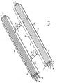
- Base element of the busbar system shown in Fig. 1 is a metal or sheet metal existing U-shaped mounting rail 1, which is fastened with its center leg 2 by fastening means not shown on a support, such as a ceiling or a room wall.
- the cover of the open lower side of the support rail 1 is effected by a cover rail 5.
- this cover rail 5 is part of a mounted on the mounting rail 1 lamp module, in Fig. 1, only the contacting element of the lamp module in the form of a Drehabgriffs 50th is shown, but not its other components, such as the lamp or the associated control or operating device, which may be an electronic ballast (ECG).
- ECG electronic ballast
- the interior of the mounting rail 1 then serves as a receiving space for the operating devices of the lamps in this case.
- 1 Stromleitprofile are arranged on the inner sides of the two side walls 3a and 3b of the support rail, which are inventively formed by a plurality of plastic and composite wire support members 10, each containing two side wings 10a and 10b with a plurality of grooves 11 for receiving the wires 6 ,
- five wires 6 are arranged in the right side wing 10a, while six wires 6 extend on the left side.
- the light By contacting the corresponding wires 6 of the connected light can be assigned a desired function, for example, the light can be used as an emergency light.
- the two control cables for lighting control there is the possibility of using these two Lines to form a bus system over which a plurality of lights can be controlled by means of digital control commands, as is known from more complex lighting systems ago.
- the terminal contact 53 by means of a support member 55 is arranged vertically adjustable on the Drehabgriff 50. By simply moving the support member 55 thus the light connected to the busbar light can be assigned the desired function.
- a wire element 62 guided in a slot 63 of the rotary handle 50 is also provided, the end 62b of which contacts the left lower wire 6 provided for earthing.
- the detailed structure and operation of the contacting element 50 will be explained in more detail later.
- the power supply for the busbar system can be done for example by a suitably adapted Drehabgriff, which is positioned in the longitudinal direction at any point.
- a secure mounting of the two side wings 10a, 10b of the wire retaining element 10 is effected by a plurality of guide arms 12 1 - 12 4 , which engage in corresponding guide grooves 4 1 - 4 4 of the U-shaped mounting rail 1.
- the lined up to a Stromleitprofil several wire retaining elements 10 are inserted during assembly in the longitudinal direction in the support rail 2.
- a plurality of support struts 16 At the back of the side wings 10a and 10b, ie on the side opposite the contacting side of the grooves 11 are a plurality of support struts 16, which ensure a stable mounting of the grooves 11 within the support rail 2, so that they are not pushed back when contacting. In this way, a reliable contacting of the wires 6 is supported.
- connection of the two side wings 10a and 10b takes place at regular intervals via connecting webs 13, which are arranged on the center leg 2 of the support rail 1.
- the connecting webs 13 further have downwardly projecting retaining legs 15, which together with a horizontally projecting from the right side wing 10 a horizontal leg 14 form an additional cavity 8.
- This cavity can be used for the storage of additional cables or lines.
- the horizontal leg 14 still has the task of preventing the contacting element 50 is inserted laterally into the support rail 1, as will also be explained later.
- the shape of the grooves 11 of the wire holder elements 10 is selected such that a contact protection is ensured, as will be explained below with reference to FIG. 2.
- the support rail 1 is shown with a Stromleitprofil disposed therein, but now without the Drehabgriff 50.
- the initially mentioned safety standard provides that the arranged in the Stromleitprofil wires 6 may not be exposed so that a 1mm-thick test wire 7 in straight ahead -Extension on a current-carrying wire 6 can meet.
- the entry angle for the test wire 7 is the most favorable for the wire 6 arranged on the bottom left. As can be seen in FIG.
- the widths, depths and opening shapes of the grooves 11 are dimensioned such that even at the smallest entry angle the test wire 7 can not contact any of the wires 6. In this way, unintentional contact with the wires 6 is avoided and the corresponding safety standard is met.
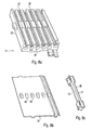
- FIG. 3 showing a wire retaining element 10 in a perspective view.
- Essential elements of the wire holder element 10 are the two side wings 10a and 10b, which have the grooves 11 for supporting the wires. They are connected to each other via two connecting bridges 13. In this way, in addition with the help of the horizontal leg 14 and the projecting from the connecting webs 13 retaining legs 15 of the aforementioned cavity 8 can be formed, which can be used to support other useful for the lighting system cables or cables.
- On the two side wings 10a, 10b are also also also the guide arms 12 1 to 12 4 , which engage in the recesses 4 1 to 4 4 of the support rail 1 during insertion.
- FIG. 3 and FIG. 4 show the wire-holding element 10 immediately after production.
- the side wings 10a and 10b are folded down by 90 ° about the two folding points A and B (see FIG. 4) and then inserted into the mounting rail 1, whereby the in FIGS. 1 and 2 shown arrangement results.
- the two side wings 10a and 10b on projections 17 and 22, with the help of two assembled wire holder elements 10 overlap overlapping.
- locking heads 18 are further provided, which allow removal of two assembled wire holder elements 10 in the longitudinal direction only up to a certain maximum distance, so that a composed of several wire holder elements 10 Stromleitprofil in his Length is flexible and thus changes in length of the individual made of plastic wire holder elements 10 can be compensated due to temperature differences.
- FIGS. 5 and 6 show two composite wire support elements in an enlarged view, on the one hand from the contacting side (FIG. 5) and on the other from the opposite rear side (FIG. 6).
- the parts belonging to the first wire-holding element 10 1 are provided with the index 1, while the elements belonging to the second wire-holding element 10 2 have the index 2.
- the two wire holder elements 10 1 and 10 2 engage these two overlapping each other in such a way that in each case by a projection 17, the first wire holder element 10 1 and by a projection 22 2 of the second wire holder element 10 2, a channel 23 is formed, the grooves 11 of the two wire holder elements 10 1 and 10 2 connects to each other.
- the grooves 11 of the two wire holder elements 10 1 and 10 2 connects to each other.
- all the channels 23 formed in this way are accessible only from the contacting side, ie, from above, in the connection region, but not from the side. As a result, the required contact protection is ensured even in the region of the channels 23.
- the two locking heads 18 2 allow removal of the two wire holder elements 10 1 and 10 2 only up to a maximum distance, which is predetermined by the fact that at the ends of the locking heads 18 laterally projecting locking projections 19th 2 come against stop walls 20 1 to the plant.
- the ends of the two wire holder elements 10 1 , 10 2 can approach each other so far until their two end faces 21 1 and 21 2 come into contact against each other.
- the wire holder elements 10 shown can be made of plastic in a simple manner by injection molding, whereby they are very inexpensive to manufacture. Furthermore, it is sufficient to produce wire retaining elements 10 in only a single length, since to adapt the Stromleitprofils formed to the different lengths of the wire rails only the number of wire holder elements 10 used must be adjusted, which in turn significantly reduces the manufacturing cost of the entire system.
- the interlocking projections and the locking elements can also be configured differently.
- each support rail 1 may have one or more openings in its upper region.
- the connecting rail 30 is then also provided with corresponding openings through which spring tongues protrude. The spring tongues engage behind the openings of the support rail 1, as soon as the connecting rail 30 in the mounting rail 1 the has reached the appropriate position. In order to solve the support rail 1 and the connecting rail 30 again, only pressure on the spring tongues must be exercised.
- Such a releasable connection is preferably on both sides, which means that the connecting rail 30 has next to its two ends such openings with the corresponding spring tongues.
- a connection detachable on both sides however, an embodiment is also possible which has the connection just described on one side by means of spring tongues, while on the other side of the connecting rail 30 a conventional screw connection is provided.
- the spring tongues arranged at each end of the connecting rail 30 belong to a common rail locking element which is arranged on the center leg of the connecting rail 30, the spring tongues projecting laterally through openings in the upper region of the side walls ,
- the rail-locking element is formed so that the spring tongues are retracted under the action of a force from above on the element in the interior of the connecting rail 30.
- About a provided in the middle leg of the support rails 1 additional opening the rail locking element from above in a simple manner to achieve and operate, for example by means of a screwdriver, so that the connection is released by a simple handle again.
- the wire retaining elements 10 which are not shown in FIG. 7 for reasons of clarity, have a slightly different configuration in the connecting region in order to take account of the additional connecting rail 30 arranged in the mounting rail 1.
- the wire support elements 10 have no support struts 16 in this area.
- two connecting elements 31 are provided on the side legs 30a and 30b of the connecting rail, which have the aforementioned recesses 32.
- metal connectors are arranged, which are connected from both sides with the wires to be joined together.
- the opening shape of the recesses 32 is chosen such that they meet the safety criterion of shock protection.
- the wire holding elements adjacent to the connecting elements 31 are also modified at their ends.
- identical connecting elements 31, each having six recesses 32 are arranged on both sides of the connecting rail 30. This means that the uppermost recess 32 of the arranged on the right side Connecting element 32 remains free, since the corresponding side wing 10 a has only five grooves 11 for holding five wires 6.
- the exact structure of the wire holder elements corresponding connecting elements can be used.
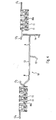
- FIG. 8 The more precise shape of a connecting element 31 is shown in FIG. 8. It consists of a box-shaped base part 33 which is open at the bottom, in which metal connectors 35 are inserted from the underside. The recesses 32 of the base part 33 are accessible from the two end faces via funnel-shaped openings 36, wherein upon insertion of a wire into a funnel-shaped opening 36, this is brought into connection with the metal connector 35. After inserting the metal connectors 35, the base part 33 is closed by a cover plate 34 from the bottom. A contacting by a luminaire module in the region of the connecting element 31 then takes place in that the terminal contacts of the contacting element are pressed against the top of a contacting plate 37 of the metal connector 35. At the end of the metal connector 35, this task is taken over again by the wires, so that no gap is formed in which a contact is not possible.
- a metal connector 35 is shown in Figs. 9a and 9b. It consists of an elongated and on their long sides a little downwardly bent contacting plate 37, whose task is to take over the electric power from the wires and forward. At the ends of the contacting plate 37 is in each case a preferably made of a chromium-nickel alloy U-shaped spring element 38, which is shown individually in Fig. 9b, respectively.
- the spring element 38 has an inwardly bent spring tongue 39, through which a wire inserted into the metal connector 35 is clamped and pressed sufficiently firmly with respect to the electrical contact resistance against the contacting plate 37.
- the wires can move or emigrate in a pump-like manner with a changing thermal expansion of the Stromleitprofils.
- the remote from the wires side of the tinned copper contacting plate 37 forms the contact surface for the contacts of the contacting element.
- To improve the contact between the contacting plate 37 and the wires has the contacting plate 37 on its underside a slightly arcuate or triangular recess 43rd
- the attachment of the spring elements 38 at the ends of the contacting plate 37 is effected by located on the side walls of the spring elements 38 recesses 40, engage in the projections 41 of the contacting plate 37.
- a stable arrangement of Metal connector 35 in the connecting element 31 is further supported by the fact that on the cover plate 34 made of plastic pins 42 are arranged, which press after mounting the cover plate 34 from the bottom against the contacting plates 37 of the metal connector 35. Since the pins 42 also engage in lateral recesses 43 of the downwardly bent longitudinal sides of the contacting plates 37, a lateral displacement of the metal connectors 35 is also prevented at the same time.
- the pins 42 also constitute a barrier by which the migration of the wires is limited.
- the connecting element shown here closes the gap between the wire-holding elements of the Stromleitprofile, so that it is possible to assemble already assembled busbars 1, with consistently contactable Stromleitprofilen, which can be contacted in the connection areas.
- this connecting element is not limited to the illustrated example with the wire retaining elements according to the invention.
- the connecting element illustrated in FIGS. 7 to 9b can also be used for the connection of the light band system mentioned in the introduction, in which the current-conducting profiles are produced by extrusion and are integral.
- an adapted Drehabgriffs for the mains supply can also be provided on the front side of a DIN rail connectable and cooperating with the metal connectors power connector element, through which the wires of the busbar system are connected to the power lines.
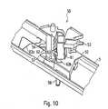
- Fig. 10 shows the Drehabgriff 50 with a arranged on its underside cover rail 5 in a perspective view.
- An essential part of the Drehabgriffs 50 are arranged on the outside of the cylindrical base body 61 contacts 53 and 54, which are adjustable in height for an optional contacting of the various wires 6.
- Another, but not freely selectable but given contact with grounding is given by the wire member 62.
- This wire element 62 is guided in a provided on the base body 61 slot 63, wherein one end 62a of the wire member 62 is fixed by clamping its shape in the cover rail 5 of the lamp module.
- the other end 62b protrudes laterally in the height of the ground wire.
- the rotary handle 50 has in its lower region two laterally projecting locking elements 52.
- the contacting of the wires 6 of the Stromleitprofils takes place in that the connected to a lighting module Drehabgriff 50 is inserted into the lower opening of the support rail 1.
- the cylindrical base body 61 is of different heights, the horizontal leg 14 arranged only on the right-hand side of the mounting rail 1 preventing the contacting element 50 from being inserted laterally into the mounting rail 1.
- the laterally disposed locking elements 52 engage inwardly projecting parts of the support rail 1 and the Stromleitprofils and thus provide a mechanical attachment of the luminaire module.
- the terminal contacts 53 and 54 are screwed into the grooves 11 of the wire support members 10, so that the desired electrical contact is made.
- some or all of the contacts may be height adjustable, which in the illustrated example is achieved by the support member 55 of the contact 53 being vertically displaceable within guide rails 56 and 57.
- the support member 55 and the cylindrical base body 61 with the guide rails 56 and 57 are designed so that the support member 55 can easily engage in the corresponding positions of the wires 6, whereby an accurate positioning of the contact 53 is facilitated.
- the slot 63 forms an eccentric stop for the wire member 62 and causes the end 62b of the wire member 62 to be pressed against the grounded left lower wire 6 during rotation of the rotary handle 50.
- a ground between the metallic cover rail 5, which is part of the luminaire module, and the metallic support rail 1 is made.
- the wire member 62 has a certain strength, which is why it preferably consists of a galvanized steel wire or a CrNi wire.
- the cover rail 5 has an elongate slot into which the rotary knob 58 can be inserted in the locked position upwards, so that it is flush with the cover rail 5 below. In this way, a complete closure of the support rail 1 is achieved.
- the cover rail 5 is also used in places where no light modules are arranged. However, in the case of fixing a luminaire module, the cover rail 5 is at the same time also the holder for all elements of the luminaire module, wherein e.g. the or the ballasts are arranged on top of the cover rail 5 and thus protrude into the interior of the U-shaped mounting rail.
- the presented rotary handle 50 makes it possible in a simple manner to make contact with the wires and to mechanically fasten the luminaire module in the busbar system.
- an application of the illustrated Drehabgriffes 50 is advantageous because it is particularly flexible and can be removed again.
- the present invention thus provides a very efficient busbar system, which for the first time offers the possibility of completely free contacting and arrangement of the luminaire modules. This has the consequence that the individual lighting modules no longer need to be adapted to certain lengths to allow a suitable arrangement within the busbar system.
- the application is not limited to the illustrated example of a U-shaped busbar.
- the wire holder elements according to the invention can also be found in busbars with other profiles, such as A-profiles or Y-profiles use. This applies in the same way also for the imaginary connecting element.
- the manufacturing cost can be significantly reduced, since the wire support members can be made in a much simpler and faster way, as is the case with the known Stromleitprofilen.
- the present invention provides a way to circumvent the problems associated with temperature differences that cause length change and displacement of the plastic parts.
Landscapes
- General Engineering & Computer Science (AREA)
- Engineering & Computer Science (AREA)
- Arrangement Of Elements, Cooling, Sealing, Or The Like Of Lighting Devices (AREA)
- Nitrogen And Oxygen Or Sulfur-Condensed Heterocyclic Ring Systems (AREA)
- Saccharide Compounds (AREA)
- Pharmaceuticals Containing Other Organic And Inorganic Compounds (AREA)
- Magnetic Bearings And Hydrostatic Bearings (AREA)
- Noodles (AREA)
- Apparatus For Radiation Diagnosis (AREA)
- Lift-Guide Devices, And Elevator Ropes And Cables (AREA)
- Installation Of Bus-Bars (AREA)
- Details Of Indoor Wiring (AREA)
- Installation Of Indoor Wiring (AREA)
Claims (16)
- Système de rails conducteurs pour luminaires, comportant plusieurs rails support (1), aptes à être assemblés entre eux de manière modulaire, ainsi qu'un profilé électroconducteur, qui est maintenu par les rails support (1) et qui comporte des rainures (11) orientées dans le sens longitudinal des rails support (1) et accessibles à partir d'un côté de connexion, en vue de recevoir des câbles (6) pour la distribution du courant et/ou pour la transmission de signaux de commande, le profilé électroconducteur, maintenu par un rail support (1), étant formé par au moins deux éléments de fixation des câbles (10, 101, 102), assemblés l'un à l'autre, lesquels comportent les rainures (11) destinées à recevoir les câbles (6), caractérisé en ce que les éléments de fixation des câbles (10, 101, 102), au moment de leur assemblage, s'engagent les uns dans les autres de manière chevauchante avec des saillies (17, 22) situées au niveau de leurs extrémités, de telle sorte que, dans la zone d'assemblage, ils forment des conduits (23) ouverts vers le côté de connexion et correspondants aux rainures (11).
- Système de rails conducteurs selon la revendication 1, caractérisé en ce que les éléments de fixation des câbles (10, 101, 102) comportent des éléments de verrouillage (18, 19), par lesquels un mouvement longitudinal relatif de deux éléments de fixation des câbles (10, 101, 102) assemblés est limité l'un vers l'autre jusqu'à un jeu prédéterminé.
- Système de rails conducteurs selon la revendication 1 ou 2, caractérisé en ce que les éléments de fixation des câbles (10, 101, 102) comportent des bras de guidage (121-124), qui s'engagent dans des rainures de guidage (41-44) correspondantes du rail support (1).
- Système de rails conducteurs selon l'une quelconque des revendications 1 à 3, caractérisé en ce que le rail support (1) est en forme de U, un profilé électroconducteur étant agencé sur les faces intérieures des deux parois latérales (3a, 3b) du rail support (1).
- Système de rails conducteurs selon la revendication 4, caractérisé en ce que le volume intérieur du rail support (1) en forme de U est destiné à former un logement pour des composants d'exploitation des lampes, ainsi pour des éléments de connexion correspondants.
- Système de rails conducteurs selon la revendication 4 ou 5, caractérisé en ce que les éléments de fixation des câbles (10, 101, 102) sont formés chacun par deux ailes latérales (10a, 10b), qui sont agencées sur les parois latérales (3a, 3b) du rail support (1) et qui comportent les rainures (11) destinées à recevoir les câbles (6), les deux ailes latérales (10a, 10b) étant reliées respectivement l'une à l'autre par des barrettes de liaison (13), qui sont disposées sur la branche centrale (2) du rail support (1).
- Système de rails conducteurs selon la revendication 6, caractérisé en ce que l'une des deux ailes latérales (10a) comporte une branche horizontale (14), qui est orientée parallèlement à la branche centrale (2) du rail support (1) et qui, conjointement avec des branches de retenue (15), en saillie sur les barrettes de liaison (13), forme un logement (8) destiné à recevoir des câbles ou lignes.
- Système de rails conducteurs selon l'une quelconque des revendications précédentes, caractérisé en ce que ledit système, en vue de relier les deux profilés électroconducteurs de deux rails support (1) consécutifs, comporte un élément de liaison (31), qui comporte des évidements (32) en forme de goulottes, qui correspondent aux rainures (11) des profilés électroconducteurs et dans lesquels est inséré respectivement un raccord métallique (35), sur les deux côtés duquel peuvent être branchés les câbles à raccorder.
- Système de rails conducteurs selon la revendication 8, caractérisé en ce que les raccords métalliques (35) sont formés par une plaquette de contact (37) allongée, aux deux extrémités de laquelle est agencé respectivement un élément ressort (38) en forme de U destiné à serrer les câbles (6) à brancher sur le raccord métallique (35).
- Système de rails conducteurs selon l'une quelconque des revendications 4 à 7 et la revendication 8 ou 9, caractérisé en ce que ledit système, en vue de relier deux rails support (1), comporte un rail de liaison (30) en forme de U, qui s'engage à l'intérieur des deux rails support (1) et sur les branches latérales (30a, 30b) duquel est agencé respectivement un élément de liaison (31).
- Système de rails conducteurs selon l'une quelconque des revendications 4 à 7 ou 10, caractérisé en ce que ledit système, en vue du branchement d'un luminaire au système de rails conducteurs, comporte un élément de connexion (50), qui comporte plusieurs contacts de connexion (53, 54) et qui peut être inséré dans l'ouverture du rail support (1) et peut tourner partiellement, afin que des contacts de connexion (53, 54) puissent être amenés sous l'effet de la rotation dans les rainures (11) du profilé électroconducteur et venir en appui contre les câbles (6) à mettre en contact.
- Système de rails conducteurs selon la revendication 11, caractérisé en ce qu'au moins un des contacts de connexion (53) est réglable en hauteur.
- Système de rails conducteurs selon la revendication 11 ou 12, caractérisé en ce que, sous l'effet de la rotation, des éléments de verrouillage (52) situés sur l'élément de connexion (50) enserrent par l'arrière des pièces en saillie du rail support (1).
- Élément de fixation des câbles pour la réalisation modulaire d'un profilé électroconducteur pour un système de rails conducteurs, lequel profilé électroconducteur comporte des rainures (11) orientées dans le sens longitudinal, accessibles à partir d'un côté de connexion et destinées à recevoir des câbles (6) pour la distribution du courant et/ou pour la transmission de signaux de commande, les éléments de fixation des câbles (10, 101, 102) comportant des rainures (11) destinées à recevoir les câbles (6), caractérisé en ce que les éléments de fixation des câbles comportent au niveau de leurs extrémités des saillies (17, 22) qui, au moment de l'assemblage avec un autre élément de fixation des câbles (10, 101, 102), s'engagent les unes dans les autres de manière chevauchante, de telle sorte que, dans la zone d'assemblage, ils forment des conduits (23) ouverts vers le côté de connexion et correspondants aux rainures (11).
- Élément de fixation des câbles selon la revendication 14, caractérisé en ce que les éléments de fixation des câbles (10, 101, 102) comportent des éléments de verrouillage (18, 19), par lesquels un mouvement longitudinal relatif de deux éléments de fixation des câbles (10, 101, 102) assemblés est limité l'un vers l'autre jusqu'à un jeu prédéterminé.
- Élément de fixation des câbles selon la revendication 14 ou 15, caractérisé en ce que ledit élément est formé par deux ailes latérales (10a, 10b), qui sont reliées l'une à l'autre par des barrettes de liaison (13), chaque branche latérale (10a, 10b) comportant au moins une rainure (11) destinée à recevoir un câble (6).
Applications Claiming Priority (3)
| Application Number | Priority Date | Filing Date | Title |
|---|---|---|---|
| DE10025647A DE10025647A1 (de) | 2000-05-24 | 2000-05-24 | Stromschienensystem |
| DE10025647 | 2000-05-24 | ||
| PCT/EP2001/002466 WO2001091248A1 (fr) | 2000-05-24 | 2001-03-05 | Systeme de rails conducteurs |
Publications (2)
| Publication Number | Publication Date |
|---|---|
| EP1284035A1 EP1284035A1 (fr) | 2003-02-19 |
| EP1284035B1 true EP1284035B1 (fr) | 2007-01-03 |
Family
ID=7643343
Family Applications (1)
| Application Number | Title | Priority Date | Filing Date |
|---|---|---|---|
| EP01923633A Expired - Lifetime EP1284035B1 (fr) | 2000-05-24 | 2001-03-05 | Systeme de rails conducteurs |
Country Status (9)
| Country | Link |
|---|---|
| EP (1) | EP1284035B1 (fr) |
| AT (1) | ATE350786T1 (fr) |
| AU (1) | AU5035901A (fr) |
| DE (2) | DE10025647A1 (fr) |
| ES (1) | ES2279807T3 (fr) |
| HU (1) | HU228403B1 (fr) |
| NO (1) | NO323118B1 (fr) |
| PL (1) | PL203264B1 (fr) |
| WO (1) | WO2001091248A1 (fr) |
Families Citing this family (18)
| Publication number | Priority date | Publication date | Assignee | Title |
|---|---|---|---|---|
| DE10216250B4 (de) * | 2002-04-12 | 2016-06-16 | Zumtobel Lighting Gmbh | Endstück für eine Stromschiene eines Stromschienensystems |
| DE102004051826A1 (de) | 2004-10-25 | 2006-05-04 | Zumtobel Staff Gmbh | Eckleuchte |
| CN200956472Y (zh) | 2006-09-29 | 2007-10-03 | 郑启文 | 具有防呆功能的电源分配系统 |
| EP1950850A1 (fr) * | 2007-01-24 | 2008-07-30 | Chi-Wen Chen | Système de distribution d'énergie |
| DE202008014905U1 (de) | 2008-04-01 | 2009-08-13 | Zumtobel Lighting Gmbh | Lichtbandsystem |
| DE102009019686A1 (de) | 2009-04-30 | 2010-11-04 | Zumtobel Lighting Gmbh | Stromleitprofil für ein Stromschienensystem |
| DE202010004781U1 (de) | 2010-04-09 | 2011-09-02 | Zumtobel Lighting Gmbh | Lichtbandsystem mit nachrüstbarer Optik |
| DE102010003805A1 (de) | 2010-04-09 | 2011-10-13 | Zumtobel Lighting Gmbh | Leuchte mit LEDs und den LEDs zugeordneten Linsen |
| DE102011085275B4 (de) | 2011-07-08 | 2021-01-28 | Zumtobel Lighting Gmbh | Optisches Element |
| DE102011079404A1 (de) | 2011-07-19 | 2013-01-24 | Zumtobel Lighting Gmbh | Anordnung zur Lichtabgabe |
| DE202012012509U1 (de) * | 2012-04-13 | 2013-03-14 | Ueberholz Gmbh | Stromversorgungsvorrichtung mit einem Grundkörper, an dem Adapter an verschiedenen Stellen befestigbar sind, wobei mindestens ein elektrischer Verbraucher von mindestens zwei Adaptern am Grundkörper befestigbar ist |
| KR101351358B1 (ko) | 2013-03-05 | 2014-01-23 | 주식회사 린노 | 라인 타입 조명장치 |
| DE102015109998B4 (de) * | 2015-06-22 | 2017-03-23 | Siteco Beleuchtungstechnik Gmbh | Leuchteneinsatz mit Drehriegel |
| DE102017125267A1 (de) * | 2017-10-27 | 2019-05-02 | Wago Verwaltungsgesellschaft Mbh | Stromführungsprofil und Stromführungsanordnung |
| EP3503312B1 (fr) * | 2017-12-19 | 2021-05-05 | Wago Verwaltungsgesellschaft mbH | Profilé de guidage de courant |
| DE102017130571A1 (de) | 2017-12-19 | 2019-06-19 | Wago Verwaltungsgesellschaft Mbh | Stromführungsprofil |
| EP3800792B1 (fr) | 2019-10-02 | 2022-08-03 | Zumtobel Lighting GmbH | Adaptateur de communication pour un système de jonction de lumière, système de jonction de lumière comportant au moins deux de ces adaptateurs de communication et procédé de communication de données dans un tel système de jonction de lumière |
| CN110762496A (zh) * | 2019-10-22 | 2020-02-07 | 深圳市艾格斯特科技有限公司 | 一种新型灯具导轨 |
Family Cites Families (6)
| Publication number | Priority date | Publication date | Assignee | Title |
|---|---|---|---|---|
| FR61514E (fr) * | 1951-02-05 | 1955-05-12 | Prises de courant automatiques | |
| GB1173549A (en) * | 1968-07-22 | 1969-12-10 | British Lighting Ind Ltd | Coupling Member for Conductors in Electrical Distribution Tracks. |
| US3832673A (en) * | 1973-02-16 | 1974-08-27 | Soquenne M | Conducting rail and adapter for supplying electrical appliance |
| US3831130A (en) * | 1973-02-22 | 1974-08-20 | Nokia Oy Ab | Coupling element for an electric current supply conduit |
| AT391382B (de) * | 1987-10-20 | 1990-09-25 | Zumtobel Ag | Adapter mit einem gehaeuse zum anschluss von lampen, insbesondere von gasentladungs- und niederspannungsgluehlampen |
| FI96909C (fi) * | 1994-11-10 | 1996-09-10 | Nokia Alumiini Oy | Kosketin |
-
2000
- 2000-05-24 DE DE10025647A patent/DE10025647A1/de not_active Ceased
-
2001
- 2001-03-05 HU HU0301888A patent/HU228403B1/hu not_active IP Right Cessation
- 2001-03-05 PL PL366148A patent/PL203264B1/pl unknown
- 2001-03-05 DE DE50111802T patent/DE50111802D1/de not_active Expired - Lifetime
- 2001-03-05 AT AT01923633T patent/ATE350786T1/de active
- 2001-03-05 ES ES01923633T patent/ES2279807T3/es not_active Expired - Lifetime
- 2001-03-05 WO PCT/EP2001/002466 patent/WO2001091248A1/fr active IP Right Grant
- 2001-03-05 AU AU50359/01A patent/AU5035901A/en not_active Abandoned
- 2001-03-05 EP EP01923633A patent/EP1284035B1/fr not_active Expired - Lifetime
-
2002
- 2002-11-22 NO NO20025642A patent/NO323118B1/no not_active IP Right Cessation
Also Published As
| Publication number | Publication date |
|---|---|
| WO2001091248A1 (fr) | 2001-11-29 |
| PL366148A1 (en) | 2005-01-24 |
| ES2279807T3 (es) | 2007-09-01 |
| HUP0301888A2 (hu) | 2003-09-29 |
| AU5035901A (en) | 2001-12-03 |
| NO20025642L (no) | 2003-01-22 |
| EP1284035A1 (fr) | 2003-02-19 |
| PL203264B1 (pl) | 2009-09-30 |
| NO20025642D0 (no) | 2002-11-22 |
| DE10025647A1 (de) | 2001-11-29 |
| HU228403B1 (en) | 2013-03-28 |
| DE50111802D1 (de) | 2007-02-15 |
| ATE350786T1 (de) | 2007-01-15 |
| NO323118B1 (no) | 2007-01-08 |
Similar Documents
| Publication | Publication Date | Title |
|---|---|---|
| EP1284033B1 (fr) | Systeme a rail conducteur | |
| EP1284034B1 (fr) | Systeme de barre omnibus | |
| EP1284035B1 (fr) | Systeme de rails conducteurs | |
| EP1016821B2 (fr) | Chemin d' éclairage avec un profil support fixable à un mur ou à un plafond | |
| WO2021069302A1 (fr) | Barre omnibus pour lampes ou unités électriques | |
| EP1994614B1 (fr) | Construction a cadre pour une armoire electrique, armoire electrique et kit pour l'armoire electrique | |
| DE2751652A1 (de) | Elektrisches kontaktschienensystem | |
| EP0616401B1 (fr) | Pile de barres omnibus | |
| EP0404979A1 (fr) | Système de rail d'éclairage | |
| EP0466043B1 (fr) | Installation de distribution comprenant au moins deux rangées d'appareils électriques de type étroit | |
| DE3903155C2 (de) | Verformbare Vorrichtung zur Verbindung von Leitungen zur Verteilung von elektrischer Energie | |
| DE2829721C3 (de) | Mosaikbaustein für Schalt- und Meldewarten | |
| EP3540304B1 (fr) | Système de réalisation d'une bande lumineuse | |
| AT17765U1 (de) | Stromschienenbauteil zum Bilden einer länglichen Stromschiene | |
| DE19706865A1 (de) | Adapter für Stromschienen | |
| EP1353415B1 (fr) | Pièce d'extrémité pour une barre omnibus dans un système de barre omnibus | |
| DE2351020C3 (de) | Stromkreisleiste | |
| DE19750100A1 (de) | Verbindungsvorrichtung | |
| EP0304513A2 (fr) | Dispositif d'éclairage à basse tension | |
| DE102021110154A1 (de) | Kontakteinrichtung mit konfigurierbarem Ergänzungsversorgungskontakt | |
| EP3876365A1 (fr) | Adaptateur d'éclairage et système d'éclairage des voies | |
| DE102012107907A1 (de) | Leuchtenmodul und Verfahren zu dessen Montage | |
| EP2355269A1 (fr) | Système de rails conducteurs pour lampes et procédé de formation d'un tel système de rail conducteur | |
| WO1990006160A1 (fr) | Rails avec support pour trains miniatures | |
| DE2814274A1 (de) | Anschlusstueck fuer eine elektrische stromverteilerschiene |
Legal Events
| Date | Code | Title | Description |
|---|---|---|---|
| PUAI | Public reference made under article 153(3) epc to a published international application that has entered the european phase |
Free format text: ORIGINAL CODE: 0009012 |
|
| 17P | Request for examination filed |
Effective date: 20021031 |
|
| AK | Designated contracting states |
Designated state(s): AT BE CH CY DE DK ES FI FR GB GR IE IT LI LU MC NL PT SE TR |
|
| AX | Request for extension of the european patent |
Extension state: SI |
|
| GRAP | Despatch of communication of intention to grant a patent |
Free format text: ORIGINAL CODE: EPIDOSNIGR1 |
|
| RAP1 | Party data changed (applicant data changed or rights of an application transferred) |
Owner name: ZUMTOBEL LIGHTING GMBH |
|
| GRAS | Grant fee paid |
Free format text: ORIGINAL CODE: EPIDOSNIGR3 |
|
| GRAA | (expected) grant |
Free format text: ORIGINAL CODE: 0009210 |
|
| AK | Designated contracting states |
Kind code of ref document: B1 Designated state(s): AT BE CH CY DE DK ES FI FR GB GR IE IT LI LU MC NL PT SE TR |
|
| AX | Request for extension of the european patent |
Extension state: SI |
|
| PG25 | Lapsed in a contracting state [announced via postgrant information from national office to epo] |
Ref country code: FI Free format text: LAPSE BECAUSE OF FAILURE TO SUBMIT A TRANSLATION OF THE DESCRIPTION OR TO PAY THE FEE WITHIN THE PRESCRIBED TIME-LIMIT Effective date: 20070103 Ref country code: IE Free format text: LAPSE BECAUSE OF FAILURE TO SUBMIT A TRANSLATION OF THE DESCRIPTION OR TO PAY THE FEE WITHIN THE PRESCRIBED TIME-LIMIT Effective date: 20070103 Ref country code: DK Free format text: LAPSE BECAUSE OF FAILURE TO SUBMIT A TRANSLATION OF THE DESCRIPTION OR TO PAY THE FEE WITHIN THE PRESCRIBED TIME-LIMIT Effective date: 20070103 |
|
| REG | Reference to a national code |
Ref country code: GB Ref legal event code: FG4D Free format text: NOT ENGLISH |
|
| REF | Corresponds to: |
Ref document number: 50111802 Country of ref document: DE Date of ref document: 20070215 Kind code of ref document: P |
|
| REG | Reference to a national code |
Ref country code: IE Ref legal event code: FG4D Free format text: LANGUAGE OF EP DOCUMENT: GERMAN |
|
| REG | Reference to a national code |
Ref country code: SE Ref legal event code: TRGR |
|
| GBT | Gb: translation of ep patent filed (gb section 77(6)(a)/1977) |
Effective date: 20070419 |
|
| PG25 | Lapsed in a contracting state [announced via postgrant information from national office to epo] |
Ref country code: PT Free format text: LAPSE BECAUSE OF FAILURE TO SUBMIT A TRANSLATION OF THE DESCRIPTION OR TO PAY THE FEE WITHIN THE PRESCRIBED TIME-LIMIT Effective date: 20070604 |
|
| ET | Fr: translation filed | ||
| REG | Reference to a national code |
Ref country code: IE Ref legal event code: FD4D |
|
| REG | Reference to a national code |
Ref country code: ES Ref legal event code: FG2A Ref document number: 2279807 Country of ref document: ES Kind code of ref document: T3 |
|
| PLBE | No opposition filed within time limit |
Free format text: ORIGINAL CODE: 0009261 |
|
| STAA | Information on the status of an ep patent application or granted ep patent |
Free format text: STATUS: NO OPPOSITION FILED WITHIN TIME LIMIT |
|
| 26N | No opposition filed |
Effective date: 20071005 |
|
| PG25 | Lapsed in a contracting state [announced via postgrant information from national office to epo] |
Ref country code: MC Free format text: LAPSE BECAUSE OF NON-PAYMENT OF DUE FEES Effective date: 20070331 |
|
| PG25 | Lapsed in a contracting state [announced via postgrant information from national office to epo] |
Ref country code: GR Free format text: LAPSE BECAUSE OF FAILURE TO SUBMIT A TRANSLATION OF THE DESCRIPTION OR TO PAY THE FEE WITHIN THE PRESCRIBED TIME-LIMIT Effective date: 20070404 |
|
| REG | Reference to a national code |
Ref country code: CH Ref legal event code: PFA Owner name: ZUMTOBEL LIGHTING GMBH Free format text: ZUMTOBEL LIGHTING GMBH#SCHWEIZERSTRASSE 30#6850 DORNBIRN (AT) -TRANSFER TO- ZUMTOBEL LIGHTING GMBH#SCHWEIZERSTRASSE 30#6850 DORNBIRN (AT) |
|
| PG25 | Lapsed in a contracting state [announced via postgrant information from national office to epo] |
Ref country code: CY Free format text: LAPSE BECAUSE OF FAILURE TO SUBMIT A TRANSLATION OF THE DESCRIPTION OR TO PAY THE FEE WITHIN THE PRESCRIBED TIME-LIMIT Effective date: 20070103 |
|
| PG25 | Lapsed in a contracting state [announced via postgrant information from national office to epo] |
Ref country code: LU Free format text: LAPSE BECAUSE OF NON-PAYMENT OF DUE FEES Effective date: 20070305 |
|
| PG25 | Lapsed in a contracting state [announced via postgrant information from national office to epo] |
Ref country code: TR Free format text: LAPSE BECAUSE OF FAILURE TO SUBMIT A TRANSLATION OF THE DESCRIPTION OR TO PAY THE FEE WITHIN THE PRESCRIBED TIME-LIMIT Effective date: 20070103 |
|
| REG | Reference to a national code |
Ref country code: CH Ref legal event code: PCAR Free format text: NEW ADDRESS: HOLBEINSTRASSE 36-38, 4051 BASEL (CH) |
|
| REG | Reference to a national code |
Ref country code: FR Ref legal event code: PLFP Year of fee payment: 16 |
|
| PG25 | Lapsed in a contracting state [announced via postgrant information from national office to epo] |
Ref country code: IT Free format text: LAPSE BECAUSE OF NON-PAYMENT OF DUE FEES Effective date: 20160305 |
|
| REG | Reference to a national code |
Ref country code: FR Ref legal event code: PLFP Year of fee payment: 17 |
|
| PGFP | Annual fee paid to national office [announced via postgrant information from national office to epo] |
Ref country code: NL Payment date: 20170327 Year of fee payment: 17 |
|
| PGFP | Annual fee paid to national office [announced via postgrant information from national office to epo] |
Ref country code: BE Payment date: 20170328 Year of fee payment: 17 |
|
| PG25 | Lapsed in a contracting state [announced via postgrant information from national office to epo] |
Ref country code: IT Free format text: LAPSE BECAUSE OF NON-PAYMENT OF DUE FEES Effective date: 20160305 |
|
| PGFP | Annual fee paid to national office [announced via postgrant information from national office to epo] |
Ref country code: ES Payment date: 20170425 Year of fee payment: 17 |
|
| PGRI | Patent reinstated in contracting state [announced from national office to epo] |
Ref country code: IT Effective date: 20170710 |
|
| REG | Reference to a national code |
Ref country code: FR Ref legal event code: PLFP Year of fee payment: 18 |
|
| PGFP | Annual fee paid to national office [announced via postgrant information from national office to epo] |
Ref country code: IT Payment date: 20180323 Year of fee payment: 18 |
|
| REG | Reference to a national code |
Ref country code: NL Ref legal event code: MM Effective date: 20180401 |
|
| REG | Reference to a national code |
Ref country code: BE Ref legal event code: MM Effective date: 20180331 |
|
| PG25 | Lapsed in a contracting state [announced via postgrant information from national office to epo] |
Ref country code: NL Free format text: LAPSE BECAUSE OF NON-PAYMENT OF DUE FEES Effective date: 20180401 |
|
| PG25 | Lapsed in a contracting state [announced via postgrant information from national office to epo] |
Ref country code: BE Free format text: LAPSE BECAUSE OF NON-PAYMENT OF DUE FEES Effective date: 20180331 |
|
| PGFP | Annual fee paid to national office [announced via postgrant information from national office to epo] |
Ref country code: CH Payment date: 20190328 Year of fee payment: 19 Ref country code: GB Payment date: 20190327 Year of fee payment: 19 Ref country code: FR Payment date: 20190328 Year of fee payment: 19 |
|
| PGFP | Annual fee paid to national office [announced via postgrant information from national office to epo] |
Ref country code: AT Payment date: 20190328 Year of fee payment: 19 Ref country code: SE Payment date: 20190328 Year of fee payment: 19 |
|
| REG | Reference to a national code |
Ref country code: ES Ref legal event code: FD2A Effective date: 20190904 |
|
| PG25 | Lapsed in a contracting state [announced via postgrant information from national office to epo] |
Ref country code: ES Free format text: LAPSE BECAUSE OF NON-PAYMENT OF DUE FEES Effective date: 20180306 |
|
| PG25 | Lapsed in a contracting state [announced via postgrant information from national office to epo] |
Ref country code: IT Free format text: LAPSE BECAUSE OF NON-PAYMENT OF DUE FEES Effective date: 20190305 |
|
| PGFP | Annual fee paid to national office [announced via postgrant information from national office to epo] |
Ref country code: DE Payment date: 20200330 Year of fee payment: 20 |
|
| REG | Reference to a national code |
Ref country code: CH Ref legal event code: PL |
|
| REG | Reference to a national code |
Ref country code: AT Ref legal event code: MM01 Ref document number: 350786 Country of ref document: AT Kind code of ref document: T Effective date: 20200305 |
|
| PG25 | Lapsed in a contracting state [announced via postgrant information from national office to epo] |
Ref country code: AT Free format text: LAPSE BECAUSE OF NON-PAYMENT OF DUE FEES Effective date: 20200305 Ref country code: CH Free format text: LAPSE BECAUSE OF NON-PAYMENT OF DUE FEES Effective date: 20200331 Ref country code: SE Free format text: LAPSE BECAUSE OF NON-PAYMENT OF DUE FEES Effective date: 20200306 Ref country code: FR Free format text: LAPSE BECAUSE OF NON-PAYMENT OF DUE FEES Effective date: 20200331 Ref country code: LI Free format text: LAPSE BECAUSE OF NON-PAYMENT OF DUE FEES Effective date: 20200331 |
|
| REG | Reference to a national code |
Ref country code: DE Ref legal event code: R071 Ref document number: 50111802 Country of ref document: DE |
|
| GBPC | Gb: european patent ceased through non-payment of renewal fee |
Effective date: 20200305 |
|
| PG25 | Lapsed in a contracting state [announced via postgrant information from national office to epo] |
Ref country code: GB Free format text: LAPSE BECAUSE OF NON-PAYMENT OF DUE FEES Effective date: 20200305 |