EP0401647B1 - Système de verrouillage - Google Patents
Système de verrouillage Download PDFInfo
- Publication number
- EP0401647B1 EP0401647B1 EP90110184A EP90110184A EP0401647B1 EP 0401647 B1 EP0401647 B1 EP 0401647B1 EP 90110184 A EP90110184 A EP 90110184A EP 90110184 A EP90110184 A EP 90110184A EP 0401647 B1 EP0401647 B1 EP 0401647B1
- Authority
- EP
- European Patent Office
- Prior art keywords
- key
- code
- locking device
- lock
- lock cylinder
- Prior art date
- Legal status (The legal status is an assumption and is not a legal conclusion. Google has not performed a legal analysis and makes no representation as to the accuracy of the status listed.)
- Expired - Lifetime
Links
Images

Classifications
-
- G—PHYSICS
- G07—CHECKING-DEVICES
- G07C—TIME OR ATTENDANCE REGISTERS; REGISTERING OR INDICATING THE WORKING OF MACHINES; GENERATING RANDOM NUMBERS; VOTING OR LOTTERY APPARATUS; ARRANGEMENTS, SYSTEMS OR APPARATUS FOR CHECKING NOT PROVIDED FOR ELSEWHERE
- G07C9/00—Individual registration on entry or exit
- G07C9/00174—Electronically operated locks; Circuits therefor; Nonmechanical keys therefor, e.g. passive or active electrical keys or other data carriers without mechanical keys
- G07C9/00182—Electronically operated locks; Circuits therefor; Nonmechanical keys therefor, e.g. passive or active electrical keys or other data carriers without mechanical keys operated with unidirectional data transmission between data carrier and locks
-
- E—FIXED CONSTRUCTIONS
- E05—LOCKS; KEYS; WINDOW OR DOOR FITTINGS; SAFES
- E05B—LOCKS; ACCESSORIES THEREFOR; HANDCUFFS
- E05B47/00—Operating or controlling locks or other fastening devices by electric or magnetic means
- E05B47/06—Controlling mechanically-operated bolts by electro-magnetically-operated detents
- E05B47/0611—Cylinder locks with electromagnetic control
- E05B47/0619—Cylinder locks with electromagnetic control by blocking the rotor
- E05B47/0623—Cylinder locks with electromagnetic control by blocking the rotor axially, i.e. with an axially engaging blocking element
-
- E—FIXED CONSTRUCTIONS
- E05—LOCKS; KEYS; WINDOW OR DOOR FITTINGS; SAFES
- E05B—LOCKS; ACCESSORIES THEREFOR; HANDCUFFS
- E05B47/00—Operating or controlling locks or other fastening devices by electric or magnetic means
- E05B47/0001—Operating or controlling locks or other fastening devices by electric or magnetic means with electric actuators; Constructional features thereof
- E05B47/0002—Operating or controlling locks or other fastening devices by electric or magnetic means with electric actuators; Constructional features thereof with electromagnets
- E05B47/0006—Operating or controlling locks or other fastening devices by electric or magnetic means with electric actuators; Constructional features thereof with electromagnets having a non-movable core; with permanent magnet
-
- E—FIXED CONSTRUCTIONS
- E05—LOCKS; KEYS; WINDOW OR DOOR FITTINGS; SAFES
- E05B—LOCKS; ACCESSORIES THEREFOR; HANDCUFFS
- E05B49/00—Electric permutation locks; Circuits therefor ; Mechanical aspects of electronic locks; Mechanical keys therefor
-
- G—PHYSICS
- G07—CHECKING-DEVICES
- G07C—TIME OR ATTENDANCE REGISTERS; REGISTERING OR INDICATING THE WORKING OF MACHINES; GENERATING RANDOM NUMBERS; VOTING OR LOTTERY APPARATUS; ARRANGEMENTS, SYSTEMS OR APPARATUS FOR CHECKING NOT PROVIDED FOR ELSEWHERE
- G07C9/00—Individual registration on entry or exit
- G07C9/00174—Electronically operated locks; Circuits therefor; Nonmechanical keys therefor, e.g. passive or active electrical keys or other data carriers without mechanical keys
- G07C2009/00753—Electronically operated locks; Circuits therefor; Nonmechanical keys therefor, e.g. passive or active electrical keys or other data carriers without mechanical keys operated by active electrical keys
- G07C2009/00761—Electronically operated locks; Circuits therefor; Nonmechanical keys therefor, e.g. passive or active electrical keys or other data carriers without mechanical keys operated by active electrical keys with data transmission performed by connected means, e.g. mechanical contacts, plugs, connectors
Definitions
- the invention relates to a locking device according to the preamble of claim 1.
- Locking systems in larger objects such as blocks of flats, schools, administrative buildings or industrial companies are usually arranged in a security hierarchy, so that only individual locks can be opened with certain keys, while keys of a higher hierarchical level fit into other locks and a general key of the highest hierarchical level opens all of them Locks enabled.
- keys of a higher hierarchical level fit into other locks and a general key of the highest hierarchical level opens all of them Locks enabled.
- people who use these objects receive the key assigned to the relevant hierarchy level.
- access control systems with card systems that work electronically are also known.
- the authorized person pushes the card into a slot, which is then read and evaluated electronically and automatically opens the relevant door when the authorization is determined.
- Such access control systems are very complex to install, but they have the advantage that the authorization of these cards can be deleted if individual cards are lost, so that the system can otherwise be operated without compromising security.
- Locking devices which represent a combination of mechanical and electronic coding, offer an increase in security compared to locking systems working with purely mechanical coding, with reduced investment costs compared to access control systems with cards.
- Such locking devices are described, for example, in a brochure by Bauer Kabaabotechnik GmbH Co. & KG.
- the invention has for its object to improve a locking device according to the preamble of claim 1 so that the locking device is faster, easier and more economical to perform when installing or upgrading existing locking systems.
- An important aspect of the invention is that the energy source is not arranged in the lock unit, but in the key. If the energy source of a key is then exhausted, there is still the possibility of opening the lock with another key, so it has not become completely unusable.
- the cumbersome exchange of an independent energy source otherwise located in the lock unit or the laying of corresponding power supply lines to the lock unit is eliminated.
- the need for space is reduced by eliminating such an energy source, so that it is possible to arrange the code evaluator with the unlocking device in the locking cylinder.
- the unlocking device comprises an electromagnetically actuated, mechanical flip-flop.
- a practical embodiment of the mechanical flip-flop comprises a magnet armature designed as a latch which, when tightened by an electromagnet, releases a bolt which can be displaced against the force of a spring.
- the latch is only briefly tightened in this embodiment and the bolt, which is biased against the spring force, can then retreat and release the rotary movement of the lock cylinder insert. Once tightened, the latch can then fall off the pole pieces and return to its starting position after the opening process and removal of the key, as soon as the bolt has returned to its end position due to the spring force.
- the spring rests stationary at one end, is supported against the bolt in the central region and carries a stop surface for the key shaft at the free end, which, when the key is inserted, has a Unlocking force exerts on the bolt.
- the same spring is thus biased by the biasing force of the key so that the bolt experiences a force in the opening direction and can relax when the key is removed, whereby the bolt receives a force in the closing direction.
- the trap is arranged under the vertically mounted electromagnet and is pivotally mounted about a horizontal axis.
- the trap can move back to its starting position without additional spring force, namely exclusively under the influence of gravity, and snap in behind the bolt.
- the unlocking device comprises an electromagnet, which via a capacitor arranged in the locking cylinder and chargeable by the energy source located in the key, if the code of Key and lock cylinder can be energized.
- the energy supply lines are designed for one polarity through the key shaft with the locking cylinder and for the other polarity through a contact at the end of the key shaft with a central contact of the locking cylinder, preferably the stop surface on the spring.
- the contact in the locking cylinder is very well protected against damage and dirt.
- the spring pressure ensures reliable contact and mechanical cleaning of the contacts. Contact resistances that otherwise occur at low operating voltages Function could be impaired in this way.
- the arrangement of the contact on the key also ensures a high short-circuit protection when carrying the key together with other keys, since practically no contact with them can take place at the end of the key.
- the contacts at the root of the key shaft on the one hand and in the locking cylinder are formed by corresponding contacts which are in alignment with the contacts on the key when the key is in the inserted state.
- An additional measure to improve short-circuit safety is that the key carries a sliding contact cover when inserted into the lock cylinder.
- This contact cover normally lies over the contacts, so that when the relevant key is carried on the key ring, contact with other keys can also not lead to bridging of the corresponding contacts for the power supply lines. Furthermore, it is also possible to provide the key with a manually operated button that is looped into the power supply lines.
- a particularly advantageous embodiment for improving the short-circuit protection and protecting the battery from undesired discharges is a solution which comprises a timer circuit in the key which only briefly releases a charging current for the charging capacitor.
- a development of this embodiment provides that the timer circuit via a The feedback line can be connected to the code evaluator in the key and can only be initialized if the code matches.
- the current required to actuate the unlocking device is only taken from the key-side energy source if the key is in the lock cylinder and the authorization to open the lock has been proven.
- a practical embodiment of the code transmitter comprises a code memory, a controller circuit for code word formation and a data transmitter
- a practical embodiment of the code evaluator comprises a data receiver, a code memory and a controller circuit for code word comparison, which is connected to a control input of the unlocking device.
- the keys and the locking cylinders of the locking device contain partially identical components, which enable cost-effective production in mass production, and differ only in the memory contents of the code memories.
- the Change authorizations because, for example, they specify different hierarchy levels for keys or delete the codes of individual keys for locking cylinders or record those of other keys.
- the code evaluator additionally comprises a data transmitter arranged in a feedback line, controlled by its controller circuit, and the code transmitter comprises a data receiver connected to its controller circuit.
- a code match signal can be transmitted to the code-side controller circuit, which serves to initialize the timer circuit.
- the authorization check takes place until the lock cylinder is released in dialog, which provides additional security against misuse and, at the same time, the key-side energy source is only used if there is authorization to open the lock.
- the energy supply lines are also provided for data transmission.
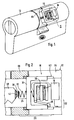
- a lock cylinder 12 is shown, which does not differ in its external design and in its dimensions from conventional mechanical lock cylinders. It can therefore be replaced with the original lock cylinder in a conventional mechanical lock.
- While vertical locking pins can be arranged in the area on the left in the drawing, which enable conventional mechanical coding, is located in the rear part of a code evaluator 16 with an unlocking device 18.
- This unlocking device serves to lock the rotary insert 66 of the locking cylinder 12.
- the unlocking device 18 is shown in detail in FIG. 2. It comprises a mechanical flip-flop 26, which consists of a displaceable latch 34, a spring 32, an electromagnet 30 and a latch 28.
- the bolt 34 is located in a longitudinal groove 62, which is located both in the housing 64 of the locking cylinder and in the rotatable part 66 and overlaps both parts in the locked state, so that a positive connection between the housing 64 of the locking cylinder 12 and the rotatable part 66 consists.
- the spring 32 is stationary at one end on the electromagnet 30 and is supported in the central region against the bolt 34. At the free end, the spring 32 carries a stop surface 36, against which the key shaft of the key 10, which is partially shown here, presses in the inserted state. In this way, the key shaft 38 exerts an unlocking force on the bolt 34. If the key 10 is removed, the Latch 34 is pressed by the spring 32 to the left against its stop and brings about the aforementioned locking between the rotatable part 66 and the housing 64 of the locking cylinder 12.
- the spring 32 When the key 10 is inserted, the spring 32 is compressed by the contact of the key shaft 38 with the stop surface 36 to such an extent that a force is exerted in the opposite direction, ie to the right.
- the displacement of the bolt 34 is blocked by the latch 28, which is arranged here vertically under the electromagnet 30 and is pivotally mounted about a horizontal axis. The trap 28 thus falls back into the starting position under the force of gravity.
- the latch 28 since it is designed as a magnet armature, is briefly attracted to the electromagnet 30 and indicates the displacement path for the bolt 34 free. After the trap 28 drops when the current pulse in the electromagnet 30 subsides, the trap 28 lies on one Leg of the bolt 34. The bolt 34 is now in the right end position and only engages in the area of the longitudinal grooves 62 located in the housing 64 of the locking cylinder 12. Thus, the positive connection between the housing 64 and the rotatable part 66 is released and the lock can be opened by turning the rotatable part by means of the key 10.
- FIG. 2 also shows the energy supply lines 22 and 24, via which electrical energy for actuating the electromagnet 30 is conducted from the energy source arranged in the key to the code evaluator 16 and the unlocking device 18.
- One power supply line 22 is formed by the key shaft and the housing 64 of the locking cylinder 12 and the other by a central contact 42 at the end of the key shaft 38 and the stop surface 36 and the spring 32. From there, conventional wiring lines lead to the code evaluator 16 and to the electromagnet 30 .
- the power supply lines 22 and 24 also serve for data transmission at the same time.
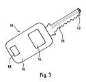
- Fig. 3 shows a plan view of a key 10 of the locking device according to the invention.
- the key 10 has a conventional key handle 70 in which a code transmitter 14 and an energy source 20 are arranged. At 68 there is also a type plate for identification of the key number.
- the key shaft 38 is located on the handle 70, which is designed here as a key bit with the usual mechanical coding. At the front end of the key shaft 38, the contact 42 can be seen, which forms one part of the energy supply lines 22, 24, while the other part is represented by the remaining key shaft 38.
- the key 10 can be used in addition to the use in locking devices of the type according to the invention in conventional locks which work as part of a locking system exclusively with mechanical coding.
- locking devices with electronic locking components also in the locking cylinder the security against misuse is increased by the additional mechanical coding.
- FIG. 4 shows a circuit diagram of the lock cylinder 12 arranged code evaluator 16. This comprises a data receiver 52, a code memory 54 and a controller circuit 56 for code word comparison. In addition, a charging capacitor 40 is provided, which supplies the energy for the unlocking device 18.
- the code memory 54 can contain the codes of one or more key numbers. If there is a match, a control signal is emitted on the one hand to the unlocking device 18, of which a switching transistor 72 and the magnet coil of the electromagnet 30 are shown here. In addition, a code match signal is transmitted back to the code transmitter 14 via a data transmitter 58.
- the charging capacitor 40 is then charged via a diode 74 and the stored charge is transferred as a current pulse to the magnetic coil of the electromagnet 30 after the switching transistor 32 has been released. This is followed by the brief tightening of the latch 28 mentioned in connection with the description of FIG. 2, so that the bolt 34 is released.
- the diode 74 in connection with the charging capacitor 40 also serves to screen the supply voltage of the electronic assemblies so that their function is not impaired by the energization of the solenoid of the electromagnet 30.
- the code transmitter 14 comprises a code memory 46, a controller circuit 48 for code word formation and a data transmitter 50.
- the energy source 20, a data receiver 60 and a timer circuit 44 are also provided.
- One or more code numbers can be contained in the code memory 46 of the code transmitter 14 if the key is, for example, the authorization for several locks of a lower one Hierarchical level.
- the stored code is transmitted from the controller circuit 48 via the data transmitter 50 to the code evaluator 16 of the locking cylinder 12. The transmission takes place here via the energy supply lines 22 and 24, the contact 42 at the end of the key shaft 38 being shown as the output.
- the energy supply of the code transmitter 14 takes place from the energy source 20 formed by a battery via resistors 76 and 78.
- the resistor 76 also forms a series resistor for the energy supply of the code evaluator 16.
- a code matching signal supplied by the code evaluator 16 passes through the data receiver 60 to the controller circuit 48 and causes the controller circuit 48 to initialize the timer circuit 44. This then switches through the switching transistor 80 for a limited time and thereby bridges the series resistor 76, so that the full charging current can flow from the energy source 20 into the charging capacitor 40. After completion of the charging process, the timer circuit 44 blocks the switching transistor 80 again.
- charging of the charging capacitor 40 does not always take place every time the key 10 comes into contact with a locking cylinder 12, rather charging is limited to the cases in which a code match has been found and energy is actually required to energize the electromagnet 30.
- the charging capacitor 40 will also charge partially via the resistors 76 and 78 even before the switching transistor 80 is switched on. If it should be shown that this amount of charge should already be sufficient to actuate the electromagnet 30, switching of the switching transistor 80 would be unnecessary, as a result of which the key's energy source could be relieved.
- the invention can also be implemented without such a charging capacitor if the energy source 20 provided in the key is dimensioned sufficiently strong. In the first working phase, when checking for code conformity, there is only a minimal load on the energy source 20 because of the very low current that the electronic circuits require.
- code memories 46, 54 can of course be reprogrammed in a manner known per se with a programming device in order to change the authorizations of a key in the desired manner.
Claims (17)
- Système de verrouillage comprenant au moins une clé (10) et une unité de serrure avec serrure et barillet (12) munies de composants électroniques de verrouillage qui comprennent un transmetteur de code (14), monté dans la clé (10) et un lecteur de code (16), monté dans l'unité de serrure avec un dispositif de déblocage (18), ainsi qu'une source d'énergie (20) et des lignes d'alimentation (22, 24) entre la clé (10) et l'unité de serrure, caractérisé en ce que la source d'énergie (20) est montée dans la clé (10) et que le lecteur de code (16) est monté dans le barillet (12), avec le dispositif de déblocage (18).
- Système de verrouillage suivant la revendication 1, caractérisé en ce que le dispositif de déblocage (18) comprend un flip-flop (26) mécanique à actionnement électro-magnétique.
- Système de verrouillage suivant la revendication 2, caractérisé en ce que le flip-flop (26) mécanique est une palette mobile de relais prévue comme un pêne (28) qui libère par l'action d'un électro-aimant (30) un verrou (34) qui peut se déplacer contre la force d'un ressort (32).
- Système de verrouillage suivant la revendication 3, caractérisé en ce que le ressort (32) est stationnaire à une extrémité, s'appuie, au centre, contre le verrou (34) et est pourvu, à son extrémité libre, d'une surface de butée (36) pour le canon de clé (38), qui, à l'introduction de la clé (10), exerce une force de déblocage sur le verrou (34).
- Système de verrouillage suivant la revendication 3 ou 4, caractérisé en ce que le pêne (28) est monté sous l'électro-aimant vertical (30) et peut tourner autour d'un axe horizontal.
- Système de verrouillage suivant l'une ou plusieurs des revendications 1 à 5, caractérisé en ce que le dispositif de déblocage (18) comprend un électro-aimant (30) alimenté en courant par un condensateur (40) disposé dans le barillet (12) et rechargeable par la source d'énergie (20) se trouvant dans la clé (10), quand il y a concordance du code entre la clé (10) et le barillet (12).
- Système de verrouillage suivant l'une ou plusieurs des revendications 1 à 6, caractérisé en ce que les lignes d'alimentation (22, 24) sont formées par le canon de clé (38) avec le barillet (12), pour une polarité, et par un contact (42) à l'extrémité du canon de clé (38), avec contact central du barillet (12), de préférence de la surface de butée (36) sur le ressort (32), pour l'autre polarité.
- Système de verrouillage suivant l'une ou plusieurs des revendications 1 à 6, caractérisé en ce que les lignes d'alimentation (22, 24) sont formées par des contacts à la base du canon de clé (38), ainsi que, à l'état enfiché, par des contacts alignés avec eux dans le barillet (12).
- Système de verrouillage suivant la revendication 7 ou 8, caractérisé en ce que la clé (10) porte une couverture de contact déplaçable à l'introduction dans le barillet (12).
- Système de verrouillage suivant la revendication 7 ou 8, caractérisé en ce que la clé (10) comprend un palpeur qui peut être actionné manuellement et qui est bouclé avec les lignes d'alimentation (22, 24).
- Système de verrouillage suivant la revendication 7 ou 8, caractérisé en ce que la clé (10) comprend un circuit de minuterie (44) qui ne libère que brièvement un courant de charge pour le condensateur de charge (40).
- Système de verrouillage suivant la revendication 11, caractérisé en ce que le circuit de minuterie (44) peut être relié au lecteur de code (16), par un circuit d'information en retour, et ne peut être initialisé que par une concordance du code.
- Système de verrouillage suivant l'une ou plusieurs des revendications 1 à 12, caractérisé en ce que le transmetteur de code (14) comprend une mémoire de code (46), un circuit de contrôle (48) pour la formation du mot code et un émetteur de données (50).
- Système de verrouillage suivant l'une ou plusieurs des revendications 1 à 12, caractérisé en ce que le lecteur de code (16) comprend un récepteur de données (52), une mémoire de code (54) et un circuit de contrôle (56) pour la comparaison du mot code, et est relié à une entrée de commande du dispositif de déblocage (18).
- Système de verrouillage suivant l'une ou plusieurs revendications 12 à 14, caractérisé en ce que le lecteur de code (16) comprend encore un émetteur de données (58) monté dans un circuit d'information en retour et commandé par son circuit de contrôle (56), et, en ce que le transmetteur de code (14) comprend un récepteur de données (60) relié à son circuit de contrôle (48), ce qui permet la transmission d'un signal de concordance de code au circuit de contrôle (48), du côté transmetteur de code, pour servir à l'initialisation du circuit de minuterie (44).
- Système de verrouillage suivant l'une ou plusieurs de revendications 1 à 15, caractérisé en ce que les lignes d'alimentation (22, 24) servent également à la transmission de données.
- Système de verrouillage suivant l'une ou plusieurs des revendications 1 à 16, caractérisé en ce que la clé (10) et le barillet (12) présentent encore un codage mécanique.
Priority Applications (1)
| Application Number | Priority Date | Filing Date | Title |
|---|---|---|---|
| AT90110184T ATE95271T1 (de) | 1989-06-06 | 1990-05-29 | Schliessvorrichtung. |
Applications Claiming Priority (2)
| Application Number | Priority Date | Filing Date | Title |
|---|---|---|---|
| DE3918445A DE3918445C1 (fr) | 1989-06-06 | 1989-06-06 | |
| DE3918445 | 1989-06-06 |
Publications (2)
| Publication Number | Publication Date |
|---|---|
| EP0401647A1 EP0401647A1 (fr) | 1990-12-12 |
| EP0401647B1 true EP0401647B1 (fr) | 1993-09-29 |
Family
ID=6382188
Family Applications (1)
| Application Number | Title | Priority Date | Filing Date |
|---|---|---|---|
| EP90110184A Expired - Lifetime EP0401647B1 (fr) | 1989-06-06 | 1990-05-29 | Système de verrouillage |
Country Status (4)
| Country | Link |
|---|---|
| EP (1) | EP0401647B1 (fr) |
| JP (1) | JPH03100286A (fr) |
| AT (1) | ATE95271T1 (fr) |
| DE (2) | DE3918445C1 (fr) |
Cited By (6)
| Publication number | Priority date | Publication date | Assignee | Title |
|---|---|---|---|---|
| EP0505084A1 (fr) * | 1991-03-19 | 1992-09-23 | Yale Security Products Limited | Serrure et combinaison serrure et clef |
| US5628217A (en) * | 1994-11-18 | 1997-05-13 | Azbe B. Zubia S.A. | Electronic-mechanical locking cylinders |
| US5791177A (en) * | 1991-10-21 | 1998-08-11 | Bianco; James S. | Compact electronic lock |
| US5826450A (en) * | 1995-05-15 | 1998-10-27 | Codatex Id-Systeme Gessellschaft Mbh | Locking device |
| US6334347B1 (en) | 1998-05-27 | 2002-01-01 | Electronic Key System (Eks) S.A.R.L. | Electronic lock with mechanical clutch |
| DE10163355C1 (de) * | 2001-12-21 | 2003-03-13 | Schliesanlagen Gmbh Pfaffenhai | Schließzylinder, insbesondere für ein Einsteckschloss |
Families Citing this family (29)
| Publication number | Priority date | Publication date | Assignee | Title |
|---|---|---|---|---|
| JP2662329B2 (ja) * | 1991-11-28 | 1997-10-08 | ホーチキ株式会社 | セキュリティ設備の鍵管理装置 |
| FR2711716B1 (fr) * | 1993-10-29 | 1995-12-15 | Setics | Dispositif de verrouillage électronique à clé. |
| DE4416318C1 (de) * | 1994-05-09 | 1995-05-11 | Ikon Praezisionstechnik | Schloß-Schlüsselsystem |
| FR2729700B1 (fr) | 1995-01-25 | 1997-07-04 | Nofal Dawalibi | Dispositif electronique de fermeture programmable |
| FR2738586A1 (fr) * | 1995-09-07 | 1997-03-14 | Valeo Electronique | Cle a contact et dispositif de verrouillage a cle et serrure l'incorporant, notamment pour vehicule automobile |
| DE19609400C2 (de) * | 1996-02-29 | 1998-05-14 | Ikon Praezisionstechnik | Schließzylinder für ein Schloß |
| US7690231B1 (en) * | 1997-02-14 | 2010-04-06 | Medeco Security Lock, Inc. | Electromechanical cylinder lock |
| FR2769034A1 (fr) * | 1997-09-29 | 1999-04-02 | Effrastop | Serrure electrique a commande et alimentation electrique exterieures codees |
| DE19755093B4 (de) * | 1997-12-11 | 2013-03-28 | Continental Teves Ag & Co. Ohg | Energieempfangsanschluss und Freigabeverfahren |
| DE19821203C1 (de) * | 1998-05-12 | 1999-10-28 | Keso Gmbh Salzburg | Schließvorrichtung |
| DE19848286B4 (de) * | 1998-10-20 | 2009-10-08 | Uhlmann, Günter | Kopplungsbaugruppe für ein Elektromechanisches Schließsystem |
| DE19853207C2 (de) * | 1998-11-18 | 2001-02-01 | Simons & Voss Identifikationss | Schließvorrichtung |
| ATE278090T1 (de) | 1999-05-06 | 2004-10-15 | Assa Abloy Ab | Schlüssel und schlossvorrichtung |
| FR2794777B1 (fr) * | 1999-06-08 | 2001-08-31 | Alain Antoniazzi | Dispositif de verrouillage/deverrouillage d'un obstacle controlant un acces et obstacle pourvu du dit dispositif |
| JP2002070375A (ja) * | 2000-09-05 | 2002-03-08 | Fujitsu Ltd | 電子鍵および電子鍵システム |
| FR2839104A1 (fr) * | 2002-04-29 | 2003-10-31 | Jacques Barnier | Dispositif de commande d'une serrure ou analogue |
| ATE472653T1 (de) * | 2005-03-30 | 2010-07-15 | Wfe Technology Corp | Zylinderschlosseinheit mit mechanischem und elektronischem mechanismus |
| EP1736622B2 (fr) | 2005-06-24 | 2020-01-08 | Assa Abloy Ab | Barillet |
| DE102006012196B3 (de) * | 2006-02-09 | 2007-08-02 | Iseo Serrature S.P.A., Pisogne | Schließzylinderanordnung |
| DE102006010794A1 (de) * | 2006-03-08 | 2007-09-13 | Hewi Heinrich Wilke Gmbh | Schlüssel mit Kontakteinrichtung |
| DE102008018906B4 (de) | 2008-04-14 | 2011-06-30 | ASTRA Gesellschaft für Asset Management mbH & Co. KG, 30890 | Schließzylinderanordnung |
| DE102009005322B4 (de) | 2009-01-16 | 2013-11-14 | Martin Lehmann Gmbh & Co. Kg | Elektronische Möbelschließeinheit |
| EP2395184A4 (fr) * | 2009-02-06 | 2012-09-19 | Xiao Ming Zhai | Barillet de serrure rotatif intelligent, à réarmement automatique et alimentation électrique par clé, ainsi que son ensemble serrure et sa clé associés |
| DE202011003043U1 (de) * | 2011-02-23 | 2011-04-21 | Meisel, Thilo | Elektrische Kontaktstelle zur Übertragung von Daten und Stromversorgung mit magnetischer Haltung und Positionierung |
| CN103895939B (zh) * | 2012-12-26 | 2016-08-03 | 中钞海思信息技术(北京)有限公司 | 防自锁型运钞袋装置 |
| CN108447713B (zh) * | 2018-05-18 | 2023-09-29 | 浙江临高电气实业有限公司 | 一种机械联锁装置的锁具、机械联锁装置、供电系统 |
| FR3119409B1 (fr) | 2021-02-04 | 2022-12-23 | Cogelec | Cylindre électronique de serrure |
| FR3119411B1 (fr) * | 2021-02-04 | 2023-10-27 | Cogelec | Procédé de fonctionnement d’un système de contrôle d'accès |
| IL282345B2 (en) * | 2021-04-14 | 2023-06-01 | Knock Nlock Ltd | Half cylinder lock |
Citations (1)
| Publication number | Priority date | Publication date | Assignee | Title |
|---|---|---|---|---|
| US4031434A (en) * | 1975-12-29 | 1977-06-21 | The Eastern Company | Keyhole-less electronic lock |
Family Cites Families (12)
| Publication number | Priority date | Publication date | Assignee | Title |
|---|---|---|---|---|
| SE7904778L (sv) * | 1978-06-06 | 1979-12-07 | Sachs Systemtechnik Gmbh | Las |
| DE2851396A1 (de) * | 1978-11-28 | 1980-06-04 | Kadex Inc | Elektronische schliessvorrichtung |
| FR2553139B2 (fr) * | 1983-01-25 | 1988-01-08 | Angelucci Marc | Dispositif de securite pour la fermeture et l'ouverture de portes, fenetres et similaires |
| CH664595A5 (de) * | 1984-03-15 | 1988-03-15 | Bauer Kaba Ag | Elektronisch-mechanischer flachschluessel. |
| FI841986A (fi) * | 1984-05-17 | 1985-11-18 | Waertsilae Oy Ab | Laosningssystem. |
| DE3509579A1 (de) * | 1985-03-16 | 1986-09-18 | Vdo Adolf Schindling Ag, 6000 Frankfurt | Zuendschluessel mit sender |
| DE8534021U1 (de) * | 1985-12-03 | 1986-03-27 | Fritz Fuss Kg, 7470 Albstadt | Schließvorrichtung mit elektronischem Identifizierungssystem |
| DE3602989A1 (de) * | 1986-01-31 | 1987-11-19 | Herz Gmbh | Elektromechanisches schlosssystem |
| WO1988000636A1 (fr) * | 1986-07-16 | 1988-01-28 | Lowe & Fletcher Limited | Serrure, cle et procede de verrouillage |
| DE3712300A1 (de) * | 1987-04-10 | 1988-10-27 | Bks Gmbh | Profilschliesszylinder, insbesondere fuer einsteckschloesser |
| DE3724407A1 (de) * | 1987-07-23 | 1989-04-06 | Blankart Johannes | Elektronischer schluessel und schloss hierfuer |
| JPH0718280B2 (ja) * | 1987-10-27 | 1995-03-01 | 本田技研工業株式会社 | キー装置 |
-
1989
- 1989-06-06 DE DE3918445A patent/DE3918445C1/de not_active Expired - Lifetime
-
1990
- 1990-05-29 EP EP90110184A patent/EP0401647B1/fr not_active Expired - Lifetime
- 1990-05-29 DE DE90110184T patent/DE59002878D1/de not_active Expired - Fee Related
- 1990-05-29 AT AT90110184T patent/ATE95271T1/de not_active IP Right Cessation
- 1990-06-06 JP JP2149738A patent/JPH03100286A/ja active Pending
Patent Citations (1)
| Publication number | Priority date | Publication date | Assignee | Title |
|---|---|---|---|---|
| US4031434A (en) * | 1975-12-29 | 1977-06-21 | The Eastern Company | Keyhole-less electronic lock |
Cited By (8)
| Publication number | Priority date | Publication date | Assignee | Title |
|---|---|---|---|---|
| EP0505084A1 (fr) * | 1991-03-19 | 1992-09-23 | Yale Security Products Limited | Serrure et combinaison serrure et clef |
| US5351042A (en) * | 1991-03-19 | 1994-09-27 | Yale Security Products Limited | Lock, key and combination of lock and key |
| US5791177A (en) * | 1991-10-21 | 1998-08-11 | Bianco; James S. | Compact electronic lock |
| US5628217A (en) * | 1994-11-18 | 1997-05-13 | Azbe B. Zubia S.A. | Electronic-mechanical locking cylinders |
| US5826450A (en) * | 1995-05-15 | 1998-10-27 | Codatex Id-Systeme Gessellschaft Mbh | Locking device |
| US6334347B1 (en) | 1998-05-27 | 2002-01-01 | Electronic Key System (Eks) S.A.R.L. | Electronic lock with mechanical clutch |
| DE10163355C1 (de) * | 2001-12-21 | 2003-03-13 | Schliesanlagen Gmbh Pfaffenhai | Schließzylinder, insbesondere für ein Einsteckschloss |
| EP1323880A2 (fr) | 2001-12-21 | 2003-07-02 | Schliessanlagen GmbH Pfaffenhain | Serrure cylindrique, notamment pour serrure encastrée |
Also Published As
| Publication number | Publication date |
|---|---|
| EP0401647A1 (fr) | 1990-12-12 |
| DE59002878D1 (de) | 1993-11-04 |
| DE3918445C1 (fr) | 1990-12-20 |
| ATE95271T1 (de) | 1993-10-15 |
| JPH03100286A (ja) | 1991-04-25 |
Similar Documents
| Publication | Publication Date | Title |
|---|---|---|
| EP0401647B1 (fr) | Système de verrouillage | |
| DE3040559C2 (fr) | ||
| EP0278906A1 (fr) | Dispositif de fermeture électromécanique | |
| WO1982000847A1 (fr) | Dispositif pour le verrouillage electronique code de serrures | |
| DE19930054C5 (de) | Elektromechanisches Schließsystem | |
| EP0224607B1 (fr) | Dispositif de fermeture comportant un système électronique d'identification | |
| DE3602989A1 (de) | Elektromechanisches schlosssystem | |
| DE3145665A1 (de) | Schliessvorrichtung | |
| EP0187363B1 (fr) | Clef codée mécaniquement et non-mécaniquement, ainsi que serrure actionnée au moyen de cette clef | |
| EP0276444B1 (fr) | Dispositif de verrouillage avec un grand nombre de combinaisons de verrouillage | |
| DE2122124A1 (de) | Elektrisches Überwachungssystem | |
| EP0094592A1 (fr) | Dispositif de fermeture | |
| DE3031405C2 (de) | Schließanlage | |
| DE3409391A1 (de) | Magneto - elektronisches system zum oeffnen und schliessen von schloessern | |
| DE19613460C2 (de) | Elektronisches Sicherheitstürschloß für eine Schließanlage | |
| DE19749081C2 (de) | Elektronisch-mechanisches Schließsystem | |
| EP0346769B1 (fr) | Dispositif de fermeture comportant une liaison codée pour imprimante | |
| DE3040532C2 (de) | Nachladbare elektronische Frankiermaschine | |
| EP0290010A2 (fr) | Appareil de commutation codé destiné à actionner une porte | |
| DE8534021U1 (de) | Schließvorrichtung mit elektronischem Identifizierungssystem | |
| DE202007004763U1 (de) | Zuhaltungsschloss | |
| DE102015113243B4 (de) | Drahtlos mit einer Zentraleinheit kommunizierendes Schranktürschloss | |
| DE10358439B4 (de) | Waren- oder Dienstleistungsautomat | |
| EP0342430A2 (fr) | Serrure pour porte | |
| DE60129117T2 (de) | Sicherheitssystem |
Legal Events
| Date | Code | Title | Description |
|---|---|---|---|
| PUAI | Public reference made under article 153(3) epc to a published international application that has entered the european phase |
Free format text: ORIGINAL CODE: 0009012 |
|
| AK | Designated contracting states |
Kind code of ref document: A1 Designated state(s): AT BE CH DE DK ES FR GB GR IT LI LU NL SE |
|
| 17P | Request for examination filed |
Effective date: 19901227 |
|
| 17Q | First examination report despatched |
Effective date: 19930318 |
|
| GRAA | (expected) grant |
Free format text: ORIGINAL CODE: 0009210 |
|
| AK | Designated contracting states |
Kind code of ref document: B1 Designated state(s): AT BE CH DE DK ES FR GB GR IT LI LU NL SE |
|
| PG25 | Lapsed in a contracting state [announced via postgrant information from national office to epo] |
Ref country code: SE Effective date: 19930929 Ref country code: NL Effective date: 19930929 Ref country code: GR Free format text: LAPSE BECAUSE OF FAILURE TO SUBMIT A TRANSLATION OF THE DESCRIPTION OR TO PAY THE FEE WITHIN THE PRESCRIBED TIME-LIMIT Effective date: 19930929 Ref country code: ES Free format text: THE PATENT HAS BEEN ANNULLED BY A DECISION OF A NATIONAL AUTHORITY Effective date: 19930929 Ref country code: DK Effective date: 19930929 Ref country code: BE Effective date: 19930929 |
|
| REF | Corresponds to: |
Ref document number: 95271 Country of ref document: AT Date of ref document: 19931015 Kind code of ref document: T |
|
| REF | Corresponds to: |
Ref document number: 59002878 Country of ref document: DE Date of ref document: 19931104 |
|
| ITF | It: translation for a ep patent filed |
Owner name: DE DOMINICIS & MAYER S. |
|
| ET | Fr: translation filed | ||
| GBT | Gb: translation of ep patent filed (gb section 77(6)(a)/1977) |
Effective date: 19940106 |
|
| NLV1 | Nl: lapsed or annulled due to failure to fulfill the requirements of art. 29p and 29m of the patents act | ||
| PG25 | Lapsed in a contracting state [announced via postgrant information from national office to epo] |
Ref country code: AT Effective date: 19940529 |
|
| PG25 | Lapsed in a contracting state [announced via postgrant information from national office to epo] |
Ref country code: LU Free format text: LAPSE BECAUSE OF NON-PAYMENT OF DUE FEES Effective date: 19940531 |
|
| PLBE | No opposition filed within time limit |
Free format text: ORIGINAL CODE: 0009261 |
|
| STAA | Information on the status of an ep patent application or granted ep patent |
Free format text: STATUS: NO OPPOSITION FILED WITHIN TIME LIMIT |
|
| 26N | No opposition filed | ||
| PGFP | Annual fee paid to national office [announced via postgrant information from national office to epo] |
Ref country code: GB Payment date: 19980406 Year of fee payment: 9 |
|
| PGFP | Annual fee paid to national office [announced via postgrant information from national office to epo] |
Ref country code: DE Payment date: 19980411 Year of fee payment: 9 |
|
| PGFP | Annual fee paid to national office [announced via postgrant information from national office to epo] |
Ref country code: FR Payment date: 19980417 Year of fee payment: 9 |
|
| PGFP | Annual fee paid to national office [announced via postgrant information from national office to epo] |
Ref country code: CH Payment date: 19980528 Year of fee payment: 9 |
|
| PG25 | Lapsed in a contracting state [announced via postgrant information from national office to epo] |
Ref country code: GB Free format text: LAPSE BECAUSE OF NON-PAYMENT OF DUE FEES Effective date: 19990529 |
|
| PG25 | Lapsed in a contracting state [announced via postgrant information from national office to epo] |
Ref country code: LI Free format text: LAPSE BECAUSE OF NON-PAYMENT OF DUE FEES Effective date: 19990531 Ref country code: CH Free format text: LAPSE BECAUSE OF NON-PAYMENT OF DUE FEES Effective date: 19990531 |
|
| REG | Reference to a national code |
Ref country code: CH Ref legal event code: PL |
|
| GBPC | Gb: european patent ceased through non-payment of renewal fee |
Effective date: 19990529 |
|
| PG25 | Lapsed in a contracting state [announced via postgrant information from national office to epo] |
Ref country code: FR Free format text: LAPSE BECAUSE OF NON-PAYMENT OF DUE FEES Effective date: 20000131 |
|
| PG25 | Lapsed in a contracting state [announced via postgrant information from national office to epo] |
Ref country code: DE Free format text: LAPSE BECAUSE OF NON-PAYMENT OF DUE FEES Effective date: 20000301 |
|
| REG | Reference to a national code |
Ref country code: FR Ref legal event code: ST |
|
| PG25 | Lapsed in a contracting state [announced via postgrant information from national office to epo] |
Ref country code: IT Free format text: LAPSE BECAUSE OF NON-PAYMENT OF DUE FEES;WARNING: LAPSES OF ITALIAN PATENTS WITH EFFECTIVE DATE BEFORE 2007 MAY HAVE OCCURRED AT ANY TIME BEFORE 2007. THE CORRECT EFFECTIVE DATE MAY BE DIFFERENT FROM THE ONE RECORDED. Effective date: 20050529 |