EP1736622B2 - Barillet - Google Patents
Barillet Download PDFInfo
- Publication number
- EP1736622B2 EP1736622B2 EP05013640.7A EP05013640A EP1736622B2 EP 1736622 B2 EP1736622 B2 EP 1736622B2 EP 05013640 A EP05013640 A EP 05013640A EP 1736622 B2 EP1736622 B2 EP 1736622B2
- Authority
- EP
- European Patent Office
- Prior art keywords
- segments
- segment
- lock cylinder
- knob
- cylinder according
- Prior art date
- Legal status (The legal status is an assumption and is not a legal conclusion. Google has not performed a legal analysis and makes no representation as to the accuracy of the status listed.)
- Expired - Lifetime
Links
Images


Classifications
-
- E—FIXED CONSTRUCTIONS
- E05—LOCKS; KEYS; WINDOW OR DOOR FITTINGS; SAFES
- E05B—LOCKS; ACCESSORIES THEREFOR; HANDCUFFS
- E05B47/00—Operating or controlling locks or other fastening devices by electric or magnetic means
- E05B47/06—Controlling mechanically-operated bolts by electro-magnetically-operated detents
- E05B47/0676—Controlling mechanically-operated bolts by electro-magnetically-operated detents by disconnecting the handle
- E05B47/0684—Controlling mechanically-operated bolts by electro-magnetically-operated detents by disconnecting the handle radially
- E05B47/0692—Controlling mechanically-operated bolts by electro-magnetically-operated detents by disconnecting the handle radially with a rectilinearly moveable coupling element
-
- E—FIXED CONSTRUCTIONS
- E05—LOCKS; KEYS; WINDOW OR DOOR FITTINGS; SAFES
- E05B—LOCKS; ACCESSORIES THEREFOR; HANDCUFFS
- E05B47/00—Operating or controlling locks or other fastening devices by electric or magnetic means
- E05B47/06—Controlling mechanically-operated bolts by electro-magnetically-operated detents
- E05B47/0611—Cylinder locks with electromagnetic control
- E05B47/0615—Cylinder locks with electromagnetic control operated by handles, e.g. by knobs
-
- E—FIXED CONSTRUCTIONS
- E05—LOCKS; KEYS; WINDOW OR DOOR FITTINGS; SAFES
- E05B—LOCKS; ACCESSORIES THEREFOR; HANDCUFFS
- E05B47/00—Operating or controlling locks or other fastening devices by electric or magnetic means
- E05B47/06—Controlling mechanically-operated bolts by electro-magnetically-operated detents
- E05B47/0611—Cylinder locks with electromagnetic control
- E05B47/0638—Cylinder locks with electromagnetic control by disconnecting the rotor
- E05B47/0646—Cylinder locks with electromagnetic control by disconnecting the rotor radially
- E05B47/0649—Cylinder locks with electromagnetic control by disconnecting the rotor radially with a rectilinearly moveable coupling element
-
- E—FIXED CONSTRUCTIONS
- E05—LOCKS; KEYS; WINDOW OR DOOR FITTINGS; SAFES
- E05B—LOCKS; ACCESSORIES THEREFOR; HANDCUFFS
- E05B9/00—Lock casings or latch-mechanism casings ; Fastening locks or fasteners or parts thereof to the wing
- E05B9/04—Casings of cylinder locks
- E05B9/045—Modular casings for adjusting the length of cylinder locks
Definitions
- the invention relates to a lock cylinder with a knob, and a lock cylinder housing, in which a knob shaft rotatable by means of the knob is rotatably mounted on one or both sides, and with electrical and / or electronic and / or magnetic and / or electromagnetic and / or electromechanical and / or mechanical functional elements, which include at least one locking element and at least one electromechanically operating coupling means which, on the basis of an authorization signal, connects the locking element to the knob shaft in a rotationally fixed manner and / or releases the knob shaft in order to actuate a lock, and evaluation electronics which are based on an input or a Input signal generates the authorization signal.
- the lock cylinder which can be actuated on one side, can be designed as a half cylinder.
- Lock cylinders of this type are generally known.
- the arrangement is often such that the input signal is detected by an antenna which excites a transponder in a chip or a similar token which is carried by the person requesting access.
- the received input signal contains the access code, which is evaluated by the evaluation electronics.
- an authorization signal is generated which controls an electromechanical coupling means.
- the coupling means causes a rotationally fixed connection between the closing element, for example a locking lug, and the knob or releases the knob shaft. An actuation of the lock or a switch or the like is then possible with the lock cylinder.
- the DE 103 28 297 A1 describes the arrangement of a locking lug on a rotating sleeve, which is freely rotatable on the knob shaft.
- the coupling means is arranged in the knob shaft and, on the basis of the authorization signal, drives a driver into a recess in the rotating sleeve.
- the locking lug is thus connected to the knob shaft in a rotationally fixed manner.
- the DE 198 51 308 C2 discloses a locking cylinder that can be operated on both sides by a knob.
- the evaluation electronics and the antenna for receiving a wirelessly transmitted signal are arranged in the knob on the inside of the door.
- the arrangement of the evaluation electronics in the knob has the disadvantage that it is relatively easily accessible and manipulable there.
- the space in the knob can then no longer be used for other functional elements, in particular for reading units for detecting the input signals or for communication units or for larger batteries.
- the knob then builds relatively large and cannot be mounted on all doors, especially not on frame doors.
- a large knob also has an unattractive visual appearance.
- document EP 1 443 162 discloses a lock cylinder, in particular profile cylinder, with a shaft, a component arranged essentially concentrically to the shaft and a coupling arrangement for coupling the shaft to the component, the coupling arrangement comprising at least one coupling element, which is between a coupling position in which the coupling element, the shaft and the Component positively connected to each other in the direction of rotation, and is displaceable to a decoupling position in which the shaft and the component are decoupled from each other in the direction of rotation, and has a drive which is designed to move a drive member, thereby displacing the coupling member.
- At least one permanent magnet is arranged on the drive element and / or on the coupling element, which is designed to displace the coupling element when the drive element moves.
- the invention has for its object to design a locking cylinder of the type mentioned in a different way.
- the disadvantages of the prior art listed above are to be avoided.
- At least one electrical and / or electronic and / or magnetic functional element is arranged in the knob, which is electrically connected to the functional elements in the knob shaft in the assembled position.
- the knob rotates with the knob shaft, so that no slip ring contacts are required either on the knob or on the functional elements located in the knob shaft. Rather, a completely assembled knob shaft with one or two knobs can be provided, all of the functional elements for the electromechanical actuation of a locking cylinder thus taking place without slip ring contacts. Trouble-free operation is therefore guaranteed.
- At least one electrical or electronic or magnetic functional element is arranged in the knob, which is electrically connected to the functional elements in the knob shaft in the assembled position.
- the knob turns with the knob shaft, so that no slip ring contacts are required between the functional elements located in the knob and those on the knob shaft.
- a completely assembled knob shaft with one or two knobs can be provided, which has all functional elements for the electromechanical actuation of a locking cylinder.
- the lock cylinder housing then only serves as a bearing for the knob shaft.
- the functional element in the knob can comprise an energy source. It is expedient if the functional element in the knob comprises a reading unit for detecting an input or receiving an input signal, which is connected to the evaluation electronics.
- the knob is in an exposed position on the door and is therefore suitable for holding a reading unit.
- the reading unit or the communication unit are preferably designed such that they generate an access signal that can be evaluated or read out directly by the evaluation electronics. This has the advantage that different reading units can be combined with a single evaluation electronics. Knobs with reading units with different reading technologies, input means or the like or communication units with different interfaces, such as infrared interface, contact plug or radio interface, can be kept ready, which can be combined in a modular manner with the knob shaft. A lock cylinder optimized for the environmental conditions or usage requirements can be put together.
- the reading unit or the communication unit is assigned to the evaluation electronics via an identification code or signal. This can be transmitted with the access signal. Provision can also be made for an identification code to be transmitted during the installation of a reading unit or communication unit or to be called up by the evaluation electronics.
- the identification code uniquely assigns the reading unit to a specific evaluation electronics and thus to a specific locking cylinder.
- the authorization signal is only generated if the identification code on the one hand and the access signal on the other hand are correct. This prevents a simple exchange of the reading units for unauthorized actuation of locks.
- the knob shaft consists of at least two and preferably of several segments which can be connected to one another in a rotationally fixed manner and that at least one functional element is arranged in at least one segment.
- a module system is provided for the knob shaft, the components of which can be selected and combined according to the requirements.
- the segments can be designed as sleeves or shaft pieces, the end edges of which have interlocking projections and recesses.
- At least one segment is designed as a terminal segment and carries the knob or is provided with a receptacle for the knob. It is particularly expedient if the cutouts and projections on the opposite end edges of at least one segment and in particular all segments lying between the terminal segments in the assembled position are designed and arranged such that the segments can be joined together as desired.
- An almost arbitrarily designed knob shaft with different functions can thus be combined, since each segment can always be combined with any other segment, which together form a uniform knob shaft. Only the terminal segments can only be joined on one side with other segments.
- the segments may be glued in the assembled position. This enables a particularly firm connection between the individual segments. However, it can also be provided that the segments are locked together and / or jammed in the assembled position. This allows a detachable connection, so that repairs or an exchange of segments is possible.
- At least the terminal segments of the assembled knob shaft can be axially fixed in the lock cylinder housing and hold the segments arranged between them. Then no connection between the segments would be necessary.
- At least the evaluation electronics is arranged in at least one segment.
- At least the coupling means can be arranged in another segment.
- a third type of segment can be provided which carries the closing element.
- the closing element can comprise a closing lug which can be connected to the knob shaft in a rotationally fixed manner by means of a locking pin driven by the coupling means.
- both the evaluation electronics and the coupling means and the closing element are arranged.
- the battery can be arranged in a further segment, for example.
- a segment carrying at least one functional element can also be designed as a terminal segment.
- the segments may be of different lengths.
- a set of segments of different lengths can thus be provided with the coupling means, with the evaluation electronics and the like.
- at least one segment is designed as an extension segment which can be fitted between any two segments. Then only one type of segment needs to be provided for each or more functional elements.
- the desired length of the knob shaft for locking cylinders of different lengths can then be generated by one or more extension segments.
- the segments have transmission means for transmitting an electrical signal or a current from an adjacent segment to the other adjacent segment.
- This is also necessary in particular for the extension segment, so that an electrical connection can be effected from a functional element in one segment to a functional element in another segment.
- the segments preferably have corresponding transmission means with electrical contacts, which bring about the electrical connection when adjacent segments are joined together. It can thus be achieved that the extension segments need to be inserted between the other segments in a simple manner, depending on the desired length, which at the same time brings about the required electrical connection of the functional elements in the segments.
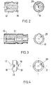
- the knob shaft 11 shown in the drawing for a double knob cylinder, which can be actuated on both sides with a knob, consists of several segments 12, 13, 14, 15, which can be joined together in a rotationally fixed manner.
- the arrangement is such that several segments can be inserted between the terminal segments 12, 15 until the desired length of the knob shaft is reached.
- the segments 13, 14 lying between the terminal segments 12, 15 have corresponding projections 16 and recesses 17 which engage in a form-fitting manner in the assembled position and bring about the rotationally fixed connection.
- the projections and recesses on the opposite end faces 18, 19 of the segments 13, 14 always match one another, so that the inner segments 13, 14 can be joined together as desired.
- the locking cylinder comprises several functional elements for the electromechanical actuation of a lock, not shown.
- the functional elements required for this include a coupling means that, based on an authorization signal, connects a locking element 20 in a rotationally fixed manner to the knob shaft 11, evaluation electronics 21, which generates the authorization signal on the basis of an input signal, and, for example, a reading unit 22 for wireless reception of the input signal.
- a battery 23 is also required in order to supply the electrical or electronic functional elements with energy.
- the evaluation electronics 21 are arranged in the terminal segment 15.
- the coupling means 30 is mounted in the segment 14.
- the segment has a corresponding installation space 24 in which, for example, an electric motor with eccentric gear 31, an electromagnetic drive or a rotating magnet can be arranged.
- a pin 32 is moved back and forth in an opening 25, which engages in a recess in the closing element 20 and brings about the rotationally fixed connection.
- the battery 23 is accommodated in the knob 26, which is connected to the terminal segment 15 in a rotationally fixed manner.
- the reading unit 22 with antenna 27 is arranged in the opposite knob 28, which is connected in a rotationally fixed manner to the terminal segment 13.
- the projections 16 of the terminal segment 13 fit into the recesses 17 of the segment 14 or also of the opposite terminal segment 15.
- the projections 16 of the segment 14 fit into the recesses 17 of the terminal segment 15.
- extension segments 13 are provided which can be inserted between the individual segments 12, 14, 15.
- they have corresponding projections 16 and recesses 17, which each cooperate with the recesses 17 or projections 16 of another segment 12, 13, 14, 15. This allows a knob shaft of any length to be installed.
- the arrangement will be such that the central segment 14, which carries the coupling means and the locking element 20, lies in the locking cylinder such that the locking element can be rotated with the usual locking lug in the area between the two cylindrical receptacles of the locking cylinder housing.
- the end segment 12 directly adjoins the knob 28 at one end.
- an extension segment 13 is also present between the segments 12, 15 in order to form a longer knob shaft.
- extension segment 13 which is inserted between the segment 14 and the terminal segment 15.
- extension segment 13 For longer knob shafts, several or longer extension segments 13 can be installed.
- a grid of 5 mm is preferably provided because the lengths of the receptacles of the locking cylinder also vary in 5 mm steps. With today's locking cylinders, the shortest receiving length is 30 mm. It is therefore expedient if the common length section of the central segment 14 and of the terminal segment 12, which is located in the receptacle in the installed position, is no longer than approximately 30 mm. Otherwise, the terminal segment would have to be designed to receive the coupling means. The same applies to the opposite segment 15.
- knob shaft all electrical and electronic functional elements are present on the knob shaft and rotate with them.
- Cables can be provided for signal transmission and current transmission between the functional elements, which are guided through corresponding cable channels 29 of the individual segments.
- the cable channels 29 of the individual segments are in alignment in the assembled position, so that one or more cables can be passed through.
- permanently installed electrical conductors can also be present in the segments and in particular in the extension segments, which in the mounted position bring about the electrical signal transmission via aligned contacts.
- knob shaft that can be easily adapted to lock cylinder housings of different lengths.
- the knob shaft is ultimately composed of several individual functional segments, which can be joined together with uniform extension sleeves or directly to obtain the desired knob shaft with the desired functions and the desired length. Additional functional elements can be arranged in the knobs, which interact with the functional elements in the knob shaft.
- a modular system is created that can be expanded and changed almost as required to fulfill the desired functions.
Landscapes
- Physics & Mathematics (AREA)
- Electromagnetism (AREA)
- Engineering & Computer Science (AREA)
- Mechanical Engineering (AREA)
- Lock And Its Accessories (AREA)
Claims (14)
- Barillet avec un bouton (26, 28) et un carter de barillet, dans lequel un arbre de bouton est disposé de façon à pouvoir tourner sur un côté ou sur les deux côtés et avec des éléments fonctionnels électriques ou magnétiques ou mécaniques dont font partie au moins un élément de fermeture (20) et au moins un moyen d'embrayage (30) fonctionnant de façon électromécanique qui relie l'élément de fermeture solidairement en rotation à l'arbre de bouton (11) sur la base d'un signal d'actionnement ou libère l'arbre de bouton, pour actionner une serrure, ainsi qu'un système électronique d'analyse (21) produisant le signal d'actionnement sur la base d'une entrée ou d'un signal d'entrée, caractérisé en ce que l'arbre de bouton (11) se compose d'au moins deux et de préférence de multiples segments (12, 13, 14, 15) reliés entre eux solidairement en rotation, qu'au moins un segment comporte au moins un élément fonctionnel (20, 21) et qu'au moins le système électronique d'analyse (21) est disposé dans au moins un segment (15).
- Barillet selon la revendication 1, caractérisé en ce que les segments (12, 13, 14,15) sont réalisés sous la forme de douilles ou de parties d'arbre dont les bords avant s'imbriquant les uns dans les autres comportent des saillies (16) et des évidements (17).
- Barillet selon l'une quelconque des revendications 1 ou 2, caractérisé en ce qu'au moins un segment (12, 15) est réalisé sous la forme d'un segment terminal et supporte le bouton (26, 28) ou comporte un logement pour le bouton.
- Barillet selon l'une quelconque des revendications 1 à 3, caractérisé en ce que les évidements (17) et les saillies (16) sont réalisées et disposées de telle sorte sur les bords avant (18, 19) opposés d'au moins un segment (13, 14) et notamment de tous les segments situés entre les segments terminaux (12, 15) dans la position montée que les segments peuvent être assemblés de façon quelconque.
- Barillet selon l'une quelconque des revendications 1 à 4, caractérisé en ce que les segments sont collés dans la position montée ou bloqués ou coincés entre eux.
- Barillet selon l'une quelconque des revendications 1 à 5, caractérisé en ce qu'au moins les segments terminaux de l'arbre de bouton monté dans le carter de barillet sont disposés de façon fixe dans le plan axial et maintiennent entre eux les segments intercalés.
- Barillet selon l'une quelconque des revendications 1 à 6, caractérisé en ce qu'au moins le moyen d'embrayage (30) est disposé dans au moins un segment (14).
- Barillet selon l'une quelconque des revendications 1 à 7, caractérisé en ce qu'au moins un segment (14) supporte au moins l'élément de fermeture (20).
- Barillet selon l'une quelconque des revendications 1 à 8, caractérisé en ce qu'au moins un segment est réalisé sous la forme d'un segment de prolongement (13) pouvant être monté entre deux segments quelconques.
- Barillet selon l'une quelconque des revendications 1 à 9, caractérisé en ce qu'au moins une partie des segments comporte respectivement au moins un caniveau pour les câbles (29) pour au moins un câble électrique aligné au moins avec le caniveau pour les câbles du segment connexe.
- Barillet selon l'une quelconque des revendications 1 à 10, caractérisé en ce que les segments comportent des moyens de transmission pour la transmission d'un signal électrique ou d'un courant depuis un segment connexe jusqu'à un autre segment connexe.
- Barillet selon l'une quelconque des revendications 1 à 11, caractérisé en ce que les segments dotés d'au moins un élément fonctionnel comportent des moyens de transmission pour la transmission d'un signal électrique ou d'un courant vers ou depuis l'élément fonctionnel.
- Barillet selon l'une quelconque des revendications 11 ou 12, caractérisé en ce que les moyens de transmission comportent des contacts électriques entraînant la liaison électrique lors de l'assemblage de segments connexes.
- Barillet selon l'une quelconque des revendications 1 à 13, caractérisé en ce que les segments de l'arbre de bouton sont réalisés de façon modulaire, les segments pouvant être pourvus de différents éléments fonctionnels et être combinés avec eux.
Priority Applications (1)
| Application Number | Priority Date | Filing Date | Title |
|---|---|---|---|
| EP05013640.7A EP1736622B2 (fr) | 2005-06-24 | 2005-06-24 | Barillet |
Applications Claiming Priority (1)
| Application Number | Priority Date | Filing Date | Title |
|---|---|---|---|
| EP05013640.7A EP1736622B2 (fr) | 2005-06-24 | 2005-06-24 | Barillet |
Publications (3)
| Publication Number | Publication Date |
|---|---|
| EP1736622A1 EP1736622A1 (fr) | 2006-12-27 |
| EP1736622B1 EP1736622B1 (fr) | 2016-12-28 |
| EP1736622B2 true EP1736622B2 (fr) | 2020-01-08 |
Family
ID=35426968
Family Applications (1)
| Application Number | Title | Priority Date | Filing Date |
|---|---|---|---|
| EP05013640.7A Expired - Lifetime EP1736622B2 (fr) | 2005-06-24 | 2005-06-24 | Barillet |
Country Status (1)
| Country | Link |
|---|---|
| EP (1) | EP1736622B2 (fr) |
Families Citing this family (10)
| Publication number | Priority date | Publication date | Assignee | Title |
|---|---|---|---|---|
| DE102006001265C5 (de) * | 2006-01-10 | 2010-04-08 | Seccor High Security Gmbh | Verlängerbare Achse für elektronische Schließzylinder |
| DE102006001266C5 (de) * | 2006-01-10 | 2009-10-22 | Seccor High Security Gmbh | Elektronischer Schließzylinder |
| FR2928678A1 (fr) * | 2008-03-14 | 2009-09-18 | Parkeon Soc Par Actions Simpli | Serrure destinee a bloquer une premiere structure par rapport a une deuxieme structure, ensemble, horodateur et procede correspondants |
| ES2331864B1 (es) * | 2008-07-15 | 2010-10-28 | Salto Systems, S.L. | Cilindro electromecanico para cerradura. |
| DE202008013172U1 (de) * | 2008-10-06 | 2010-02-25 | Burg-Wächter Kg | Schloss, insbesondere Einsteckschloss für eine Tür |
| EP2864991B1 (fr) * | 2012-06-20 | 2023-07-26 | Inelxia Limited | Mécanisme de connexion et de déconnexion de deux pièces |
| WO2014060547A1 (fr) * | 2012-10-17 | 2014-04-24 | Dorma Gmbh + Co. Kg | Ferrure de porte |
| DE102014104607B3 (de) * | 2014-04-01 | 2015-09-17 | Dom Sicherheitstechnik Gmbh & Co Kg | Elektromechanische Kupplungsanordnung mit magnetischem Drehschalter und Verfahren |
| DE102014104792B4 (de) | 2014-04-03 | 2015-11-19 | Dom-Sicherheitstechnik Gmbh & Co. Kg | Kupplungsanordnung für einen Schließzylinder mit Doppeldruckfeder |
| DE102014104793B4 (de) | 2014-04-03 | 2015-11-05 | Dom-Sicherheitstechnik Gmbh & Co. Kg | Kupplungsanordnung für Schließzylinder mit Lauffeder |
Citations (2)
| Publication number | Priority date | Publication date | Assignee | Title |
|---|---|---|---|---|
| EP0995864A2 (fr) † | 1998-10-20 | 2000-04-26 | Günter Uhlmann | Système de verrouillage électromécanique |
| DE10235201A1 (de) † | 2002-08-01 | 2004-02-19 | Günter Uhlmann | Türschließystem |
Family Cites Families (11)
| Publication number | Priority date | Publication date | Assignee | Title |
|---|---|---|---|---|
| US4534194A (en) * | 1981-03-16 | 1985-08-13 | Kadex, Incorporated | Electronic lock system |
| DE3918445C1 (fr) | 1989-06-06 | 1990-12-20 | Anatoli Dipl.-Ing. 3013 Barsinghausen De Stobbe | |
| US6374653B1 (en) | 1997-12-22 | 2002-04-23 | Security People, Inc. | Mechanical/electronic lock and key therefor |
| DE19923786A1 (de) | 1998-06-03 | 1999-12-09 | Dom Sicherheitstechnik | Schließzylinder |
| EP0962610A3 (fr) * | 1998-06-03 | 2002-10-30 | DOM Sicherheitstechnik GmbH & Co KG | Serrure cylindrique |
| DE19824713A1 (de) | 1998-06-03 | 1999-12-16 | Dom Sicherheitstechnik | Schließzylinder |
| FR2791383B1 (fr) | 1999-03-26 | 2001-04-20 | Andre Merle | Cylindre modulaire pour serrure |
| ES2205952B1 (es) * | 1999-07-27 | 2005-04-16 | Talleres De Escoriaza, S.A. | Cilindro de cerradura. |
| US6474122B2 (en) | 2000-01-25 | 2002-11-05 | Videx, Inc. | Electronic locking system |
| DE10303220B3 (de) * | 2003-01-23 | 2004-09-16 | Dom Sicherheitstechnik Gmbh & Co Kg | Schließzylinder |
| US7113070B2 (en) | 2003-03-21 | 2006-09-26 | Sheng Bill Deng | Door lock and operation mechanism |
-
2005
- 2005-06-24 EP EP05013640.7A patent/EP1736622B2/fr not_active Expired - Lifetime
Patent Citations (2)
| Publication number | Priority date | Publication date | Assignee | Title |
|---|---|---|---|---|
| EP0995864A2 (fr) † | 1998-10-20 | 2000-04-26 | Günter Uhlmann | Système de verrouillage électromécanique |
| DE10235201A1 (de) † | 2002-08-01 | 2004-02-19 | Günter Uhlmann | Türschließystem |
Also Published As
| Publication number | Publication date |
|---|---|
| EP1736622A1 (fr) | 2006-12-27 |
| EP1736622B1 (fr) | 2016-12-28 |
Similar Documents
| Publication | Publication Date | Title |
|---|---|---|
| EP1636454B1 (fr) | Barillet electromagnetique | |
| EP1574643B1 (fr) | Cylindre de serrure électromécanique | |
| EP1739631B1 (fr) | Serrure cylindrique modulaire | |
| DE69320683T2 (de) | Elektromechanische Schlossanordnung | |
| EP2201535B1 (fr) | Dispositif de verrouillage | |
| AT515703B1 (de) | Verriegelungsvorrichtung | |
| DE19930054C5 (de) | Elektromechanisches Schließsystem | |
| EP1736622B2 (fr) | Barillet | |
| EP0995864B1 (fr) | Système de verrouillage électromécanique | |
| EP1256671B1 (fr) | Rosette pour serrure cylindrique | |
| EP2998485B1 (fr) | Bouton rotatif destine a actionner un adaptateur de cylindre d'un barillet | |
| WO1992022720A1 (fr) | Serrure a ame de cylindre motorisee | |
| DE102007011554B4 (de) | Koppeleinheit für elektronische Schließ-Systeme | |
| EP1659238B1 (fr) | Cylindre de fermeture | |
| EP4200500B1 (fr) | Clé dotée d'une tête de clé, d'un arbre de clé et d'un générateur | |
| EP1369825B1 (fr) | Cylindre de fermeture pour la transmission d'un signal sans contact | |
| EP3839178B1 (fr) | Serrure de meuble pourvu de boîtier électronique logé pivotant et son procédé de fonctionnement | |
| DE102004055980B4 (de) | Verschlusseinheit mit Schloss zur Verwendung an oder in Wertbehältern, Waren- und Dienstleistungsautomaten oder dergleichen | |
| DE29911356U1 (de) | Antennenanordnung für ein durch Funksignal betätigbares Schließsystem | |
| EP3293329B1 (fr) | Loqueteau de porte d'armoire doté de module d'émission-réception | |
| EP1124207A1 (fr) | Système de verrouillage | |
| EP1703042A1 (fr) | Rosette pour barillet électromécanique | |
| DE20023578U1 (de) | Schließsystem |
Legal Events
| Date | Code | Title | Description |
|---|---|---|---|
| PUAI | Public reference made under article 153(3) epc to a published international application that has entered the european phase |
Free format text: ORIGINAL CODE: 0009012 |
|
| AK | Designated contracting states |
Kind code of ref document: A1 Designated state(s): AT BE BG CH CY CZ DE DK EE ES FI FR GB GR HU IE IS IT LI LT LU MC NL PL PT RO SE SI SK TR |
|
| AX | Request for extension of the european patent |
Extension state: AL BA HR LV MK YU |
|
| RAP1 | Party data changed (applicant data changed or rights of an application transferred) |
Owner name: HID GMBH |
|
| 17P | Request for examination filed |
Effective date: 20070622 |
|
| AKX | Designation fees paid |
Designated state(s): DE FR GB IT NL |
|
| 17Q | First examination report despatched |
Effective date: 20071029 |
|
| RAP1 | Party data changed (applicant data changed or rights of an application transferred) |
Owner name: ASSA ABLOY AB |
|
| GRAP | Despatch of communication of intention to grant a patent |
Free format text: ORIGINAL CODE: EPIDOSNIGR1 |
|
| INTG | Intention to grant announced |
Effective date: 20160718 |
|
| GRAS | Grant fee paid |
Free format text: ORIGINAL CODE: EPIDOSNIGR3 |
|
| STAA | Information on the status of an ep patent application or granted ep patent |
Free format text: STATUS: GRANT OF PATENT IS INTENDED |
|
| GRAA | (expected) grant |
Free format text: ORIGINAL CODE: 0009210 |
|
| STAA | Information on the status of an ep patent application or granted ep patent |
Free format text: STATUS: THE PATENT HAS BEEN GRANTED |
|
| AK | Designated contracting states |
Kind code of ref document: B1 Designated state(s): DE FR GB IT NL |
|
| RAP1 | Party data changed (applicant data changed or rights of an application transferred) |
Owner name: ASSA ABLOY AB |
|
| REG | Reference to a national code |
Ref country code: GB Ref legal event code: FG4D Free format text: NOT ENGLISH |
|
| REG | Reference to a national code |
Ref country code: DE Ref legal event code: R096 Ref document number: 502005015463 Country of ref document: DE |
|
| REG | Reference to a national code |
Ref country code: NL Ref legal event code: FP |
|
| REG | Reference to a national code |
Ref country code: FR Ref legal event code: PLFP Year of fee payment: 13 |
|
| REG | Reference to a national code |
Ref country code: DE Ref legal event code: R026 Ref document number: 502005015463 Country of ref document: DE |
|
| PLBI | Opposition filed |
Free format text: ORIGINAL CODE: 0009260 |
|
| 26 | Opposition filed |
Opponent name: DORMAKABA DEUTSCHLAND GMBH Effective date: 20170926 |
|
| PLAX | Notice of opposition and request to file observation + time limit sent |
Free format text: ORIGINAL CODE: EPIDOSNOBS2 |
|
| RIC2 | Information provided on ipc code assigned after grant |
Ipc: E05B 47/06 20060101AFI20171108BHEP |
|
| PLBB | Reply of patent proprietor to notice(s) of opposition received |
Free format text: ORIGINAL CODE: EPIDOSNOBS3 |
|
| REG | Reference to a national code |
Ref country code: FR Ref legal event code: PLFP Year of fee payment: 14 |
|
| PUAH | Patent maintained in amended form |
Free format text: ORIGINAL CODE: 0009272 |
|
| STAA | Information on the status of an ep patent application or granted ep patent |
Free format text: STATUS: PATENT MAINTAINED AS AMENDED |
|
| 27A | Patent maintained in amended form |
Effective date: 20200108 |
|
| AK | Designated contracting states |
Kind code of ref document: B2 Designated state(s): DE FR GB IT NL |
|
| REG | Reference to a national code |
Ref country code: DE Ref legal event code: R102 Ref document number: 502005015463 Country of ref document: DE |
|
| REG | Reference to a national code |
Ref country code: NL Ref legal event code: FP |
|
| P01 | Opt-out of the competence of the unified patent court (upc) registered |
Effective date: 20230530 |
|
| PGFP | Annual fee paid to national office [announced via postgrant information from national office to epo] |
Ref country code: NL Payment date: 20240515 Year of fee payment: 20 |
|
| PGFP | Annual fee paid to national office [announced via postgrant information from national office to epo] |
Ref country code: GB Payment date: 20240509 Year of fee payment: 20 |
|
| PGFP | Annual fee paid to national office [announced via postgrant information from national office to epo] |
Ref country code: DE Payment date: 20240507 Year of fee payment: 20 |
|
| PGFP | Annual fee paid to national office [announced via postgrant information from national office to epo] |
Ref country code: IT Payment date: 20240513 Year of fee payment: 20 Ref country code: FR Payment date: 20240524 Year of fee payment: 20 |
|
| REG | Reference to a national code |
Ref country code: DE Ref legal event code: R071 Ref document number: 502005015463 Country of ref document: DE |
|
| REG | Reference to a national code |
Ref country code: NL Ref legal event code: MK Effective date: 20250623 |
|
| PG25 | Lapsed in a contracting state [announced via postgrant information from national office to epo] |
Ref country code: GB Free format text: LAPSE BECAUSE OF EXPIRATION OF PROTECTION Effective date: 20250623 |
|
| REG | Reference to a national code |
Ref country code: GB Ref legal event code: PE20 Expiry date: 20250623 |