EP1636454B1 - Barillet electromagnetique - Google Patents
Barillet electromagnetique Download PDFInfo
- Publication number
- EP1636454B1 EP1636454B1 EP04737108A EP04737108A EP1636454B1 EP 1636454 B1 EP1636454 B1 EP 1636454B1 EP 04737108 A EP04737108 A EP 04737108A EP 04737108 A EP04737108 A EP 04737108A EP 1636454 B1 EP1636454 B1 EP 1636454B1
- Authority
- EP
- European Patent Office
- Prior art keywords
- lock
- knob
- coupling element
- driver
- lock cylinder
- Prior art date
- Legal status (The legal status is an assumption and is not a legal conclusion. Google has not performed a legal analysis and makes no representation as to the accuracy of the status listed.)
- Not-in-force
Links
Images


Classifications
-
- E—FIXED CONSTRUCTIONS
- E05—LOCKS; KEYS; WINDOW OR DOOR FITTINGS; SAFES
- E05B—LOCKS; ACCESSORIES THEREFOR; HANDCUFFS
- E05B47/00—Operating or controlling locks or other fastening devices by electric or magnetic means
- E05B47/06—Controlling mechanically-operated bolts by electro-magnetically-operated detents
- E05B47/0676—Controlling mechanically-operated bolts by electro-magnetically-operated detents by disconnecting the handle
- E05B47/0684—Controlling mechanically-operated bolts by electro-magnetically-operated detents by disconnecting the handle radially
- E05B47/0692—Controlling mechanically-operated bolts by electro-magnetically-operated detents by disconnecting the handle radially with a rectilinearly moveable coupling element
-
- E—FIXED CONSTRUCTIONS
- E05—LOCKS; KEYS; WINDOW OR DOOR FITTINGS; SAFES
- E05B—LOCKS; ACCESSORIES THEREFOR; HANDCUFFS
- E05B47/00—Operating or controlling locks or other fastening devices by electric or magnetic means
- E05B47/06—Controlling mechanically-operated bolts by electro-magnetically-operated detents
- E05B47/0611—Cylinder locks with electromagnetic control
- E05B47/0638—Cylinder locks with electromagnetic control by disconnecting the rotor
- E05B47/0646—Cylinder locks with electromagnetic control by disconnecting the rotor radially
- E05B47/0649—Cylinder locks with electromagnetic control by disconnecting the rotor radially with a rectilinearly moveable coupling element
-
- E—FIXED CONSTRUCTIONS
- E05—LOCKS; KEYS; WINDOW OR DOOR FITTINGS; SAFES
- E05B—LOCKS; ACCESSORIES THEREFOR; HANDCUFFS
- E05B47/00—Operating or controlling locks or other fastening devices by electric or magnetic means
- E05B47/0001—Operating or controlling locks or other fastening devices by electric or magnetic means with electric actuators; Constructional features thereof
- E05B2047/0014—Constructional features of actuators or power transmissions therefor
- E05B2047/0018—Details of actuator transmissions
- E05B2047/0024—Cams
- E05B2047/0025—Cams in the form of grooves
-
- E—FIXED CONSTRUCTIONS
- E05—LOCKS; KEYS; WINDOW OR DOOR FITTINGS; SAFES
- E05B—LOCKS; ACCESSORIES THEREFOR; HANDCUFFS
- E05B47/00—Operating or controlling locks or other fastening devices by electric or magnetic means
- E05B2047/0048—Circuits, feeding, monitoring
- E05B2047/0067—Monitoring
-
- E—FIXED CONSTRUCTIONS
- E05—LOCKS; KEYS; WINDOW OR DOOR FITTINGS; SAFES
- E05B—LOCKS; ACCESSORIES THEREFOR; HANDCUFFS
- E05B47/00—Operating or controlling locks or other fastening devices by electric or magnetic means
- E05B47/0001—Operating or controlling locks or other fastening devices by electric or magnetic means with electric actuators; Constructional features thereof
- E05B47/0012—Operating or controlling locks or other fastening devices by electric or magnetic means with electric actuators; Constructional features thereof with rotary electromotors
-
- Y—GENERAL TAGGING OF NEW TECHNOLOGICAL DEVELOPMENTS; GENERAL TAGGING OF CROSS-SECTIONAL TECHNOLOGIES SPANNING OVER SEVERAL SECTIONS OF THE IPC; TECHNICAL SUBJECTS COVERED BY FORMER USPC CROSS-REFERENCE ART COLLECTIONS [XRACs] AND DIGESTS
- Y10—TECHNICAL SUBJECTS COVERED BY FORMER USPC
- Y10T—TECHNICAL SUBJECTS COVERED BY FORMER US CLASSIFICATION
- Y10T70/00—Locks
- Y10T70/70—Operating mechanism
- Y10T70/7051—Using a powered device [e.g., motor]
- Y10T70/7062—Electrical type [e.g., solenoid]
- Y10T70/7102—And details of blocking system [e.g., linkage, latch, pawl, spring]
-
- Y—GENERAL TAGGING OF NEW TECHNOLOGICAL DEVELOPMENTS; GENERAL TAGGING OF CROSS-SECTIONAL TECHNOLOGIES SPANNING OVER SEVERAL SECTIONS OF THE IPC; TECHNICAL SUBJECTS COVERED BY FORMER USPC CROSS-REFERENCE ART COLLECTIONS [XRACs] AND DIGESTS
- Y10—TECHNICAL SUBJECTS COVERED BY FORMER USPC
- Y10T—TECHNICAL SUBJECTS COVERED BY FORMER US CLASSIFICATION
- Y10T70/00—Locks
- Y10T70/70—Operating mechanism
- Y10T70/7051—Using a powered device [e.g., motor]
- Y10T70/7062—Electrical type [e.g., solenoid]
- Y10T70/713—Dogging manual operator
Definitions
- the invention relates to an electromechanical lock cylinder, which can cooperate with an evaluation for detecting an access authorization and having a housing which comprises two opposing cylindrical receptacles in which either a respective lock core, which is actuated by a key, or in each case a knob shaft, the rotatably connected to a knob, are rotatably supported, wherein the lock cores or the knob shafts interact with a locking lug, which can in particular actuate a latch or a latch of a door lock, and with matching key or access authorization an electromechanically driven locking or coupling element of the Resting position is moved into an operative position and generates a rotationally fixed connection between the key or knob and the locking lug, while the locking lug od in the rest position of the locking or coupling element relative to both locking cores it is freely rotatable to both Knaufwellen.
- the lock cylinder may comprise a housing comprising two opposed cylindrical receptacles in which on one side of the housing a lock core which is actuated by a key, and on the opposite side a knob shaft which is rotatably connected to a knob, are rotatably mounted. It is also possible that the lock cylinder has a housing which comprises a cylindrical receptacle in which either a lock core, which can be actuated by a key, or a knob shaft, which is rotatably connected to a knob, is rotatably mounted, wherein the lock core or the knob shaft cooperate with a locking lug.
- the invention thus relates firstly to two-sided lock cylinder with two opposing receptacles in which either a lock core on either side or both sides a knob shaft or in which on one side a knob shaft and on the other side a lock core are stored.
- the invention relates to one-sided lock cylinder, so-called half cylinder, with only one receptacle in which either a lock core or a knob shaft is rotatably mounted.
- electromechanical lock cylinders that can be actuated with a key, in addition to a frequently still mechanically matching key also requires a matching electronically readable code to produce an operative connection between the key and the locking lug.
- the electronically readable code can be supplied wirelessly via transponder or via electrical contacts to a transmitter.
- the evaluation electronics controls the electromechanical locking or coupling element so that the locking lug can be rotated.
- Such lock cylinders are known in different embodiments.
- Such a lock cylinder is, for example, by the DE 199 30 054 A1 disclosed.
- the arrangement is such that on one side of the cylinder housing a rotary knob is present, the rotationally fixed on the Knock shaft is connected to the locking lug. An actuation is therefore always possible from this page.
- On the opposite side of the lock cylinder can be actuated by a key, which additionally carries an electrical coding.
- the electronic evaluation unit is located in the rotary knob, and the decoding signal must be passed from arranged in the cylinder housing antenna via at least one slip ring contact to the electronic evaluation.
- slip ring contacts are relatively expensive to manufacture in the required reliability.
- a lock cylinder is known in which the locking lug is freely rotatable in the rest position relative to the lock core.
- the non-rotatable connection between the lock core and locking lug is effected by an axially displaceable sleeve.
- the DE 196 03 320 A1 describes a lock cylinder in which the rotationally fixed connection between the closing lug and the lock core is produced by a cam extending by means of centrifugal force.
- the WO 02/088492 A2 discloses a locking pin for a locking core, which is driven via an eccentric and arranged in the lock cylinder housing.
- a problem with such lock cylinders when the lock cylinder from both sides should be closed only with appropriate access authorization by means of a knob and / or a key.
- the closing lug is then fixedly connected to the lock core and / or the knob shaft, which is or is locked via a locking element mounted in the cylinder housing. It can be applied in particular by a rotary knob relatively high forces that are sufficient to destroy the blocking element. Forcible opening is therefore possible.
- the invention has for its object to make a lock cylinder different so that a reliable operation in a compact design is possible.
- the locking or coupling element is arranged on or in the lock core or on or in the knob shaft and rotates with this or this and includes an eccentric, a driver between the rest position and the active position - And moved, in which it engages in a recess of the locking lug or a rotary sleeve, on which the locking lug is arranged.
- This has the advantage that there is no connection to the locking lug without access authorization. Without access authorization, the locking lug therefore can not be operated with an externally accessible element even in the case of violence. Also, a signal transmission via slip ring contacts is no longer required, so that the reliability and reliability can be increased.
- the locking or coupling element is designed as a driver, which engages in a corresponding recess in the rotary sleeve or the locking lug. It is achieved a very compact structure.
- an electric motor drive with an eccentric drive for the driver reliable operation is achieved in a very compact design.
- electric motors are easily controllable and have a relatively low power consumption.
- the electric motor in one or the other end position are switched off so that no energy is consumed after the stroke movement effected both in the rest position and in the operative position. The lifetime of the generally off-grid power supply can thus be increased.
- the closing nose is therefore freely rotatable in the rest position of the blocking or coupling element relative to both locking cores.
- a knob shaft is present on both sides of the housing, the locking lug in the rest position of the locking or coupling element is freely rotatable relative to both knob shafts.
- the locking lug in the rest position of the locking or coupling element is freely rotatable relative to the lock core and the knob shaft.
- the locking lug is freely rotatable in the rest position of the coupling element either to the lock core or to the knob shaft.
- a continuous closing core or a continuous knob shaft is present, which extends from one side of the housing to the opposite side and can be actuated from both sides by a key or a knob.
- This embodiment is advantageous, for example, if there is a rotary knob with the evaluation electronics on both sides.
- a Lock cylinder with knob shaft and lock core lock core and knob shaft can be rotatably connected together or integrally formed.
- the blocking or coupling element comprises an electromagnetic drive.
- the blocking or coupling element comprises an electric motor drive. Both electromagnets and electric motors are available with small installation dimensions, so that they can be easily integrated into the knob shaft or the lock core. Nevertheless, there is still the possibility to equip the lock core, for example, with conventional pin tumblers.
- the rest position and / or the active position of the driver are by a predeterminable angle of rotation beyond the associated dead centers of the eccentric.
- the respective angle of rotation can be 10 ° to 30 ° above the respective dead center. It is advantageous if the eccentric abuts against a stop after reaching the angle of rotation, which limits and prevents further rotation. This has the advantage that the end positions are achieved with certainty and reproducible. In particular, over-rotation beyond the end position is reliably avoided. Also, the eccentric better in these end positions, for example, by spring or locking elements whose holding force can be overcome by the engine power held.
- the eccentric drive can have an eccentrically arranged about the motor axis pin, which in a transverse to the lifting movement of the driver and perpendicular to the motor axis extending groove thereof engages the position and length is dimensioned so that a rotational movement from the rest position to the operative position only in one direction and the rotational movement of the active position in the rest position of the driver only in the opposite direction of rotation is possible.
- the motor then only needs to be controlled accordingly, namely counterclockwise to reach the rest position and clockwise to reach the active position, or vice versa. This is possible with simple technical means.
- the length and position of the groove is chosen so that further rotation of the eccentric is possible from the rest position to the operative position of the driver beyond the dead center by the rotation angle, and vice versa.
- the length of the groove in this extension which corresponds to a further rotation in the same direction of rotation is shortened, so that a further rotation beyond 90 ° and preferably beyond 45 ° is not possible to prevent spinning. This can be effected by simple means, the desired and targeted lifting movement of the driver by an eccentric.
- the locking lug is freely rotatably mounted to the knob shaft or the lock core and thus freely rotatable relative to the driver on the cylinder housing, the free end of the driver in the rest position and the recess of the locking lug are necessarily not always aligned. A movement of a rigid driver from the rest position into the active position is not possible with twisted recess.
- the driver comprises a plunger whose free end is guided in a sleeve whose free end is immersed in the operative position in the recess of the locking lug or the rotary sleeve and in the interior of which a compression spring is arranged, which cooperates with the free end of the plunger ,
- a compression spring is arranged, which cooperates with the free end of the plunger
- the sleeve has a stop on its side opposite the free end, against which a thickened end of the plunger strikes. This has the advantage that the sleeve is forcibly pulled along in a movement of the plunger in the Ruhlage. Clamping of the sleeve in the recess is avoided.
- the depth of the recess of the locking lug or the rotary sleeve is dimensioned so that when engaging driver, the compression spring in the sleeve is still under tension. This will achieve that the eccentric is held in the operative position under bias. Since the active position in the direction of rotation of the eccentric is behind the dead center, a reverse rotation of the eccentric is prevented when engaged driver.
- the driver is held in the rest position by a spring force. Since here also the rest position in the direction of rotation of the eccentric behind the associated dead center, a reverse rotation of the eccentric is prevented in a disengaged driver.
- the knob shaft 11 shown in the drawing is rotatably mounted in a hollow cylindrical receptacle 12 of a lock cylinder, not shown. Alternatively it can be stored in the wood cylindrical receptacle and a lock core, which is actuated by means of a key, in particular via mechanical tumblers.
- the knob shaft shown would be relevant here correspond to pictorial representation of a lock core, so that in the following reference is made only to the knob shaft.
- the knob shaft 11 is rotatably connected in a manner not shown with a rotary knob. It is also provided with an electronic evaluation means that can interrogate and evaluate in a known manner an electronic access code of a key or other key element.
- the lock cylinder also has a locking lug 13, which cooperates with a locking bolt of a lock, not shown.
- an electromechanically operating blocking or coupling element 14 which is described below, is activated, by means of which a rotationally fixed connection between the closing nose and the knob shaft 11 is effected. Then, the lock cylinder can be operated by the knob shaft is rotated with the knob or the lock core by means of a key. From the basic structure, the dimensions and in particular with respect to the electronic detection and evaluation of the access code corresponds to the lock cylinder so far a conventional electromechanical lock cylinder and therefore requires no further explanation.
- the arrangement is such that the locking lug is freely rotatably supported by a rotary sleeve 35 on the knob shaft in the housing.
- the electromechanically operating blocking or coupling element 14 is arranged in the knob shaft 11 and comprises an eccentric with a rotor 15, on which an axially extending pin 16 is arranged eccentrically to the eccentric axis 17.
- the pin 16 acts via a groove 18 with a driver 19 together, which moves up and down due to the rotational movement of the rotor.
- the driver 19 is guided in a guide channel 20 of the knob shaft 11 linearly and in the radial direction to the knob shaft.
- the groove 18 extends substantially transversely to the stroke direction of the driver 19.
- the position and the length of the groove are chosen so that, starting from the in Fig. 1 shown rest position, only by a rotation of the rotor 15 in the direction of rotation 21 of the driver 19 in the in Fig. 2 shown active position can be brought. From the operative position of the driver can be brought back into the rest position only by a rotation in the direction 22.
- the length and the position of the groove are chosen so that the eccentric can be rotated in its end positions in each case beyond the dead center of the respective position by a rotation angle.
- This angle can be for example 10 ° to 30 °.
- the range of the groove shown on the right in the drawing is such that further rotation of the rotor in the direction of rotation 22 by more than the predetermined rotation angle above the top dead center (rest position) is not possible because the pin 16 previously at the frontal boundary of Groove strikes. The same applies to the movement in the direction of rotation 21 beyond the bottom dead center (active position) addition.
- the driver 19 has a plunger 24, one end of which carries the groove 18 and is mounted on the pin 16 of the eccentric.
- the free end 25 of the plunger is guided in a sleeve 26.
- the opposite free end 27 of the sleeve emerges in the Fig. 2 shown active position in a recess 28 of the locking lug. Then there is a non-rotatable connection between the locking lug and the knob shaft and thus between the locking lug and the knob, and the lock can be actuated.
- a compression spring 29 is arranged, which cooperates with the free end of the plunger. It is at the opposite end of the free end of the sleeve 26, a stop 30 is provided, against which the thickened end 25 of the plunger 24 abuts.
- the sleeve is held securely on the plunger.
- the free end 27 engages only in the course of a rotary movement of the knob shaft, as soon as the free end 27 passes over the recess. This safe operation is achieved even with twisted locking lug, which in the rest position of the driver relative to the Knauf shaft and also freely rotatable to the housing of the lock cylinder.
- the free end 27 of the sleeve is formed as an expanding projection 32 with a narrower neck portion 34 and a rounded end edge. In order for a secure engagement of the projection when passing over the recess 28 is achieved when the spring 29 tensioned.
- the recess 28 of the locking lug 13 is closed in the insertion direction of the driver or a stop 33, wherein the depth of the recess is dimensioned so that when immersed projection 32, the compression spring 29 is still under tension and the free end 25 of Tappet not yet abuts the stop 30. This ensures that the eccentric pin 16 is held in tension beyond the associated dead center via the tappet and the groove in the end position of the eccentric corresponding to the active position. The eccentric can then no longer turn back by itself, for example, by gravity, even if the power supply of the drive motor is interrupted.
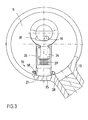
- detection means 36 are present, which detect the position or the position of the coupling element.
- the detection means may comprise at least one Hall sensor 37 and / or at least and / or at least one capacitive or inductive sensor 38 or a switch 39 which cooperates with a movable element of the coupling element.
- a Hall sensor 37 is an example of a Hall sensor 37 and in Fig. 3
- a capacitive sensor 38 in the form of a capacitor arrangement of half-rings which are influenced on the basis of the position of the driver, are shown.
- the driver is preferably made of metal, so that its position in front of the Hall sensor or between the capacitor rings can be well detected.
- Fig. 1 shows a limit switch 39, which cooperates with the eccentric of the motor.
- the limit switch can be used as Tast switch be formed, which simultaneously applies the spring force to hold the driver in the rest position behind the top dead center of the eccentric.
- a signal corresponding to the position of the coupling element and in particular of the driver can be generated by the sensors or the switch, a signal corresponding to the position of the coupling element and in particular of the driver.
- the coupling element is driven by the transmitter to move to the rest position.
- a signal is present when the coupling element is in the rest position.
- the control of the coupling element and / or the interrogation of the signal can be performed in cycles or after a predetermined period of time.
Claims (19)
- Barillet électromécanique qui peut coopérer avec une électronique d'exploitation pour détecter une autorisation d'accès et comporte un boîtier composé de deux logements cylindriques (12) situés l'un en face de l'autre, dans lesquels un noyau de fermeture pouvant être actionné par une clé ou un axe de poignée (11) solidaire en rotation avec une poignée est respectivement monté à rotation, les noyaux de fermeture ou les axes de poignée (11) coopérant avec un bec de fermeture (13) apte à actionner notamment un verrou ou un loquet d'une serrure de porte, dont lorsque la clé est adéquate ou l'autorisation d'accès a été donnée, un élément de verrouillage ou de couplage (14) à commande électromécanique est amené de la position de repos à une position active et produit une liaison résistant à la rotation entre la clé ou la poignée et le bec de fermeture, alors que le bec de fermeture (13), à la position de repos de l'élément de verrouillage ou de couplage (14), est librement rotatif relativement aux deux noyaux de fermeture ou axes de poignée,
caractérisé en ce que
l'élément de verrouillage ou de couplage (14) se situe sur ou dans le noyau de fermeture ou sur ou dans l'axe de poignée (11), avec lequel il effectue une rotation, et comprend un excentrique (15, 16) qui fait effectuer à un entraîneur (19) des mouvements de va-et-vient entre la position de repos et la position active, dans laquelle il pénètre en prise dans un évidement (28) du bec de fermeture (13) ou dans un manchon rotatif (35) portant le bec de fermeture. - Barillet selon la revendication 1,
caractérisé par
un noyau de fermeture de bout en bout ou un axe de poignée (11) de bout en bout, qui s'étend d'un côté au côté opposé du boîtier et qui peut être actionné des deux côtés par une clé ou peut effectuer une rotation au moyen d'une poignée. - Barillet électromécanique qui peut coopérer avec une électronique d'exploitation pour détecter une autorisation d'accès et comporte un boîtier composé de deux logements cylindriques (12) situés l'un en face de l'autre, dans lesquels, d'un côté du boîtier, un noyau de fermeture pouvant être actionné par une clé et, de l'autre côté, un axe de poignée (11) solidaire en rotation avec une poignée, est respectivement monté à rotation, le noyau de fermeture et/ou l'axe de poignée (11) coopérant avec un bec de fermeture (13) apte à actionner notamment un verrou ou un loquet d'une serrure de porte, dont lorsque la clé est adéquate ou l'autorisation d'accès a été donnée, un élément de verrouillage ou de couplage (14) à commande électromécanique est amené de la position de repos à une position active et produit une liaison résistant à la rotation entre la clé ou la poignée et/ ou le bec de fermeture, alors que le bec de fermeture (13), à la position de repos de l'élément de verrouillage ou de couplage (14), est librement rotatif relativement au noyau de fermeture et à l'axe de poignée,
caractérisé en ce que
l'élément de verrouillage ou de couplage (14) se situe sur ou dans le noyau de fermeture ou sur ou dans l'axe de poignée (11), avec lequel il effectue une rotation, et comprend un excentrique (15, 16) qui fait effectuer à un entraîneur (19) des mouvements de va-et-vient entre la position de repos et la position active, dans laquelle il pénètre en prise dans un évidement (28) du bec de fermeture (13) ou dans un manchon rotatif (35) sur portant le bec de fermeture. - Barillet électromécanique selon la revendication 3,
caractérisé en ce que
le noyau de fermeture et l'axe de poignée (11) sont reliés l'un à l'autre solidaires en rotation, ou réalisés en une pièce. - Barillet électromécanique qui coopère avec une électronique d'exploitation pour détecter une autorisation d'accès et comporte un boîtier comprenant un logement cylindrique dans lequel un noyau de fermeture pouvant être actionné par une clé ou un axe de poignée (11) solidaire en rotation avec une poignée est respectivement monté à rotation, le noyau de fermeture ou l'axe de poignée (11) pouvant coopérer avec un bec de fermeture (13) apte à actionner notamment un verrou ou un loquet d'une serrure de porte, dont lorsque la clé est adéquate et/ou l'autorisation d'accès a été donnée, un élément de verrouillage ou de couplage (14) à commande électromécanique est amené de la position de repos à une position active et produit une liaison résistant à la rotation entre la clé ou la poignée et le bec de fermeture, alors que le bec de fermeture (13), à la position de repos de l'élément de verrouillage ou de couplage (14), est librement rotatif relativement au noyau de fermeture et à l'axe de poignée,
caractérisé en ce que
l'élément de verrouillage ou de couplage (14) se situe sur ou dans le noyau de fermeture ou sur ou dans l'axe de poignée (11), avec lequel il effectue une rotation, et comprend un excentrique (15, 16) qui fait effectuer à un entraîneur (19) des mouvements de va-et-vient entre la position de repos et la position active, dans laquelle il pénètre en pièce dans un évidement (28) du bec de fermeture (13) ou dans un manchon rotatif (35) portant le bec de fermeture. - Barillet selon l'une des revendications 1 à 5,
caractérisé en ce que
la position de repos et/ou la position active de l'entraîneur (19) dépasse d'un angle de rotation prédéfinissable les points morts associés de l'excentrique (15, 16). - Barillet selon la revendication 6,
caractérisé en ce que
l'angle de rotation dépasse de 10° à 30° le point mort respectif. - Barillet selon l'une des revendications 1 à 7,
caractérisé en ce que
l'excentrique (15, 16) comporte une tige (16) à disposition excentrique autour d'un axe de moteur (17) d'un entraînement (23) par moteur électrique, cette tige prenant dans une rainure (18) de l'axe du moteur, s'étendant transversalement par rapport au mouvement ascendant de l'entraîneur (19) et perpendiculairement à l'axe du moteur (17), la position et la longueur de la tige étant dimensionnées de manière qu'un mouvement rotatif de la position de repos à la position active n'est possible que dans un sens de rotation, et le mouvement de rotation (21) de la position active à la position de repos de l'entraîneur (19) n'est possible que dans le sens de rotation opposé (22). - Barillet selon la revendication 8,
caractérisé en ce que
la longueur et la position de la rainure (8) sont choisies de manière à permettre à l'excentrique (15, 16) de continuer de tourner de la position de repos à la position active de l'entraîneur (19) au-delà du point mort de l'angle de rotation et vice versa. - Barillet selon l'une des revendications 1 à 9,
caractérisé en ce que
l'excentrique (19) comporte un poussoir (24) dont l'extrémité libre (25) est guidée dans un manchon, dont l'extrémité libre (27) s'enfonce, à la position active, dans l'évidement (28) du bec de fermeture (13) ou du manchon rotatif (35), et dont l'intérieur comprend un ressort de pression (29) qui coopère avec l'extrémité libre (25) du poussoir (24). - Barillet selon la revendication 10,
caractérisé en ce que
le manchon (26) est muni, sur sa face opposée à l'extrémité libre, d'une butée (30) contre laquelle l'extrémité épaissie (25) du poussoir (24) s'appuie. - Barillet selon l'une des revendications 10 ou 11,
caractérisé en ce que
la profondeur de l'évidement (28) du bec de fermeture (13) ou du manchon rotatif (35) est dimensionnée de manière que, lorsque l'entraîneur (19) prend, le ressort de pression (29) est encore sous tension dans le manchon (26). - Barillet selon l'une des revendications 1 à 12,
caractérisé en ce que
l'entraîneur (19) est maintenu en position de repos par une force de ressort. - Barillet selon l'une des revendications 1 à 13,
caractérisé en ce que
des moyens de détection (36) détectent la position ou l'emplacement de l'élément de couplage (14). - Barillet selon la revendication 14,
caractérisé en ce que
les moyens de détection (36) comprennent au moins un capteur à effet Hall (37) et/ou au moins un capteur capacitif ou inductif (38) ou un contacteur (39) qui coopère avec un élément mobile de l'élément de couplage (14). - Barillet selon la revendication 15,
caractérisé en ce que
les moyens de détection (36) coopèrent avec l'entraîneur (19). - Barillet selon la revendication 15,
caractérisé en ce que
le moyen de détection (36) détecte la position de l'excentrique (15, 16) ou de l'axe de moteur d'un entraînement (23) par moteur électrique de l'élément de verrouillage ou de couplage (14). - Barillet selon l'une des revendications 14 à 17,
caractérisé en ce que
le moyen de détection (36) produit au moins un signal ou de préférence des signaux consécutifs jusqu'à amener l'élément de couplage (14) à la position de repos, tant que l'élément de couplage (14) est en position active ou ne se trouve pas encore en position de repos et doit prendre cette position. - Barillet selon l'une des revendications 1 à 18,
caractérisé en ce que
l'élément de verrouillage ou de couplage comprend un entraînement (23) électromagnétique ou électromotorisé.
Applications Claiming Priority (2)
| Application Number | Priority Date | Filing Date | Title |
|---|---|---|---|
| DE2003128297 DE10328297A1 (de) | 2003-06-23 | 2003-06-23 | Elektromechanischer Schließzylinder |
| PCT/EP2004/006708 WO2005001224A1 (fr) | 2003-06-23 | 2004-06-22 | Barillet electromagnetique |
Publications (2)
| Publication Number | Publication Date |
|---|---|
| EP1636454A1 EP1636454A1 (fr) | 2006-03-22 |
| EP1636454B1 true EP1636454B1 (fr) | 2008-05-07 |
Family
ID=33520866
Family Applications (1)
| Application Number | Title | Priority Date | Filing Date |
|---|---|---|---|
| EP04737108A Not-in-force EP1636454B1 (fr) | 2003-06-23 | 2004-06-22 | Barillet electromagnetique |
Country Status (11)
| Country | Link |
|---|---|
| US (1) | US7874190B2 (fr) |
| EP (1) | EP1636454B1 (fr) |
| CN (1) | CN1813114B (fr) |
| AT (1) | ATE394568T1 (fr) |
| AU (1) | AU2004251188B2 (fr) |
| BR (1) | BRPI0411781A (fr) |
| CA (1) | CA2529104C (fr) |
| DE (2) | DE10328297A1 (fr) |
| MX (1) | MXPA05013454A (fr) |
| NZ (1) | NZ544843A (fr) |
| WO (1) | WO2005001224A1 (fr) |
Cited By (1)
| Publication number | Priority date | Publication date | Assignee | Title |
|---|---|---|---|---|
| EP4191000A1 (fr) * | 2021-12-03 | 2023-06-07 | dormakaba Schweiz AG | Dispositif de verrouillage électromécanique |
Families Citing this family (40)
| Publication number | Priority date | Publication date | Assignee | Title |
|---|---|---|---|---|
| DE10328297A1 (de) | 2003-06-23 | 2005-01-20 | Buga Technologies Gmbh | Elektromechanischer Schließzylinder |
| SE527207C2 (sv) | 2005-04-29 | 2006-01-17 | Assa Ab | Elektromekanisk låsanordning |
| SE0500975L (sv) | 2005-04-29 | 2006-01-24 | Assa Ab | Elektromekanisk låsanordning |
| SE527206C2 (sv) * | 2005-04-29 | 2006-01-17 | Assa Ab | Låsanordning samt sätt att montera en låsanordning |
| EP1739631B1 (fr) | 2005-06-24 | 2012-10-24 | Assa Abloy Ab | Serrure cylindrique modulaire |
| EP1736620A1 (fr) * | 2005-06-24 | 2006-12-27 | BUGA Technologies GmbH | Serrure cylindrique avec arbre de bouton bloqué |
| US20070017265A1 (en) * | 2005-07-22 | 2007-01-25 | Assa Ab | Lock device |
| DE102006001266C5 (de) * | 2006-01-10 | 2009-10-22 | Seccor High Security Gmbh | Elektronischer Schließzylinder |
| US7845202B2 (en) | 2006-09-22 | 2010-12-07 | Assa Abloy Ab | Interchangeable electromechanical lock core |
| US20080072636A1 (en) * | 2006-09-22 | 2008-03-27 | Assa Abloy Identification Technology Group Ab | Knob operated electromechanical lock cylinder |
| EP1961897A1 (fr) * | 2007-02-26 | 2008-08-27 | HID GmbH | Cylindre de verrouillage |
| DE102008018906B4 (de) * | 2008-04-14 | 2011-06-30 | ASTRA Gesellschaft für Asset Management mbH & Co. KG, 30890 | Schließzylinderanordnung |
| ES2331864B1 (es) * | 2008-07-15 | 2010-10-28 | Salto Systems, S.L. | Cilindro electromecanico para cerradura. |
| AT507583B1 (de) * | 2008-12-05 | 2010-12-15 | Evva Sicherheitstechnologie | Sperrvorrichtung |
| CN102691442A (zh) * | 2012-05-31 | 2012-09-26 | 开平百事通计算机工程有限公司 | 一种井盖电控锁的电动结构 |
| CN102677698A (zh) * | 2012-05-31 | 2012-09-19 | 开平百事通计算机工程有限公司 | 一种复合井盖连动结构 |
| CN103104152B (zh) * | 2013-02-06 | 2015-10-07 | 杭州双华智能家居有限公司 | 智能电子锁及控制方法 |
| CN103243970B (zh) * | 2013-02-06 | 2015-08-26 | 杭州双华智能家居有限公司 | 智能电子锁专用电动离合器及锁定开启方法 |
| ITTO20121114A1 (it) * | 2012-12-20 | 2014-06-21 | Rielda Serrature Srl | Serratura elettromeccanica anti-shock |
| CA2922400C (fr) | 2013-05-15 | 2019-11-05 | William Denison | Serrure |
| DE102013017214B3 (de) * | 2013-10-16 | 2015-03-05 | Pierre Meyers | Koppeleinheit für elektronische Schließ-Systeme mit Feder |
| EP2998480B1 (fr) * | 2014-09-22 | 2019-05-15 | dormakaba Deutschland GmbH | Système de contrôle d'accès électromécanique et procédé |
| US20160097220A1 (en) * | 2014-10-01 | 2016-04-07 | Yiqi Wu Woodling | Cabinet Locking Device Using an Electromagnetic Switch Actuated System with Fingerprint Identification, Combination Code and Bluetooth System |
| US10074224B2 (en) | 2015-04-20 | 2018-09-11 | Gate Labs Inc. | Access management system |
| WO2016138224A1 (fr) * | 2015-02-25 | 2016-09-01 | Triteq Lock And Security Llc | Serrure |
| DE102015105412B3 (de) * | 2015-04-09 | 2016-07-07 | Assa Abloy Sicherheitstechnik Gmbh | Schließzylinder |
| WO2016172164A1 (fr) * | 2015-04-24 | 2016-10-27 | Invue Security Products Inc. | Verrouillage auto-bloquant pour sécurité de marchandises |
| PL3241961T3 (pl) | 2016-03-21 | 2019-01-31 | Salto Systems, S.L. | Mechanizm uruchamiający sprzęgła cylindra elektronicznego do zamków |
| US10415269B2 (en) | 2016-04-14 | 2019-09-17 | Schlage Lock Company Llc | Lock cylinder with electronic key recognition |
| RU2702390C2 (ru) * | 2016-06-03 | 2019-10-08 | Корнева Ольга Павловна | Электромеханический цилиндровый замок |
| US11933076B2 (en) | 2016-10-19 | 2024-03-19 | Dormakaba Usa Inc. | Electro-mechanical lock core |
| US9822553B1 (en) | 2016-11-23 | 2017-11-21 | Gate Labs Inc. | Door tracking system and method |
| ES2927419T3 (es) | 2017-09-08 | 2022-11-07 | Dormakaba Usa Inc | Bombín de cerradura electromecánico |
| CN112752891B (zh) | 2018-04-13 | 2022-08-05 | 多玛卡巴美国公司 | 机电锁芯 |
| US11466473B2 (en) | 2018-04-13 | 2022-10-11 | Dormakaba Usa Inc | Electro-mechanical lock core |
| USD891901S1 (en) | 2019-04-05 | 2020-08-04 | Dormakaba Usa Inc. | Knob |
| DE102020104930B4 (de) | 2020-02-25 | 2021-10-14 | Uhlmann & Zacher Gmbh | Brandschutzzylinder |
| CN115288524A (zh) * | 2021-12-01 | 2022-11-04 | 宁波瑞奥物联技术股份有限公司 | 一种锁具及其控制方法 |
| ES2948342B2 (es) * | 2022-02-15 | 2024-02-07 | Salto Systems Sl | Cilindro electronico |
| US11655653B1 (en) | 2022-04-15 | 2023-05-23 | Digilock Asia Ltd. | Electronically operated lock cylinder |
Family Cites Families (73)
| Publication number | Priority date | Publication date | Assignee | Title |
|---|---|---|---|---|
| US3009349A (en) * | 1959-04-14 | 1961-11-21 | Yale & Towne Mfg Co | Removable core lock |
| US3713311A (en) * | 1971-05-28 | 1973-01-30 | R Oliver | Detachably fixed cylinder lock core |
| US4073527A (en) * | 1977-01-12 | 1978-02-14 | Schlage Lock Company | Electrically controlled door lock |
| US4123926A (en) * | 1977-07-05 | 1978-11-07 | Schlage Lock Company | Removable core cylinder lock |
| US4386510A (en) * | 1981-03-02 | 1983-06-07 | Best Lock Corporation | Key-changeable lock core |
| FR2591265B1 (fr) * | 1985-12-11 | 1988-03-25 | Llort Oscar | Serrure a armement par commande electrique a l'aide d'un electro-aimant |
| DE3602989A1 (de) | 1986-01-31 | 1987-11-19 | Herz Gmbh | Elektromechanisches schlosssystem |
| CH671800A5 (fr) * | 1987-02-09 | 1989-09-29 | Berchtold Ag | |
| US4856310A (en) * | 1987-04-29 | 1989-08-15 | Raoul Parienti | Electronic lock |
| US4810014A (en) * | 1987-08-20 | 1989-03-07 | Mcgourty Thomas K | Motor driven lock control |
| US4901545A (en) * | 1987-12-28 | 1990-02-20 | Rising Star Technologies (A Partnership) | Self-contained electromechanical locking device |
| DE8914508U1 (fr) * | 1989-02-02 | 1990-06-13 | Dom-Sicherheitstechnik Gmbh & Co Kg, 5040 Bruehl, De | |
| US4953373A (en) * | 1989-05-09 | 1990-09-04 | Ilco Unican Inc. | Key removable core body |
| US5027629A (en) * | 1990-01-22 | 1991-07-02 | Liu Yin Chic | Control mechanism of electronic lock |
| DE9004623U1 (fr) | 1990-04-24 | 1990-06-21 | Bks Gmbh, 5620 Velbert, De | |
| US5791177A (en) * | 1991-10-21 | 1998-08-11 | Bianco; James S. | Compact electronic lock |
| SE505493C2 (sv) * | 1992-03-26 | 1997-09-08 | Assa Ab | Cylinderlås |
| US5848541A (en) * | 1994-03-30 | 1998-12-15 | Dallas Semiconductor Corporation | Electrical/mechanical access control systems |
| GB9417748D0 (en) * | 1994-09-03 | 1994-10-19 | Yale Security Prod Ltd | Electrically operable cylinder lock |
| ES2106668B1 (es) * | 1994-11-18 | 1998-06-01 | Azbe B Zubia S A | Perfeccionamientos introducidos en cilindros de cierre electronicomecanico. |
| DE19517728C2 (de) * | 1995-05-15 | 1998-12-03 | Keso Gmbh | Schließvorrichtung |
| DE19525196A1 (de) | 1995-07-11 | 1997-01-16 | Danijel Golub | Zylinderschlösser mit Zieh-Pickingsschutz und Sicherheitsschlüssel |
| US6564601B2 (en) * | 1995-09-29 | 2003-05-20 | Hyatt Jr Richard G | Electromechanical cylinder plug |
| DE19603320C2 (de) * | 1996-01-31 | 1999-01-14 | Guenter Uhlmann | Elektronisch programmierbares Schließsystem mit Schloß und Schlüssel |
| DE29703559U1 (de) | 1996-03-27 | 1997-04-30 | Lerchner Leonhard | Türschloß |
| DE19615775C2 (de) * | 1996-04-20 | 1998-12-03 | Orga Kartensysteme Gmbh | Schließzylinder |
| AT407175B (de) * | 1997-04-25 | 2001-01-25 | Roto Frank Eisenwaren | Steuervorrichtung |
| DE29715137U1 (de) | 1997-08-25 | 1997-10-09 | Kuhnke Gmbh Kg H | Verriegelungsvorrichtung |
| CA2276259C (fr) * | 1997-11-05 | 2002-08-06 | Matthew O. Schroeder | Verrouillage electronique d'un cylindre de verrou standard |
| DE19861400B4 (de) | 1997-11-07 | 2013-08-01 | Simonsvoss Technologies Ag | Schließzylinder |
| DE19754923C1 (de) * | 1997-12-10 | 1999-04-01 | Sesam Elektronische Sicherheit | Türbeschlag |
| US6374653B1 (en) * | 1997-12-22 | 2002-04-23 | Security People, Inc. | Mechanical/electronic lock and key therefor |
| US6826935B2 (en) * | 1997-12-22 | 2004-12-07 | Security People, Inc. | Mechanical/electronic lock and key therefor |
| US6442986B1 (en) * | 1998-04-07 | 2002-09-03 | Best Lock Corporation | Electronic token and lock core |
| DE19822865B4 (de) | 1998-05-22 | 2006-09-28 | Aug. Winkhaus Gmbh & Co. Kg | Schließzylinder |
| FR2779168B1 (fr) * | 1998-05-27 | 2001-01-26 | Euronetics France | Serrure electronique a embrayage mecanique |
| DE19824713A1 (de) * | 1998-06-03 | 1999-12-16 | Dom Sicherheitstechnik | Schließzylinder |
| DE19919283A1 (de) * | 1998-06-03 | 1999-12-09 | Dom Sicherheitstechnik | Schließzylinder |
| AUPP400798A0 (en) * | 1998-06-11 | 1998-07-02 | Lockwood Security Products Pty Limited | Electrically controlled lock |
| US6079240A (en) * | 1998-07-24 | 2000-06-27 | Arrow Lock Manufacturing Company | Modular removable core cylinder assembly |
| DE19834691A1 (de) * | 1998-07-31 | 2000-02-03 | Wilke Heinrich Hewi Gmbh | Schließsystem |
| DE19854879C1 (de) | 1998-11-27 | 2000-08-03 | Ulf Klenk | Verschlußeinrichtung für Türen mit integrierter Antenne zur Funkfernbedienung |
| US6101856A (en) * | 1998-12-14 | 2000-08-15 | Sargent Manufacturing Company | Free-wheeling lever handle lock mechanism |
| DE19901838A1 (de) | 1999-01-19 | 2000-07-20 | Winkhaus Fa August | Elektromagnetisch aktivierbarer Sperrmechanismus |
| US6564600B1 (en) * | 1999-03-08 | 2003-05-20 | Videx, Inc. | Electronic access control device |
| DE19930054C5 (de) * | 1999-06-30 | 2006-11-23 | Buga Technologies Gmbh | Elektromechanisches Schließsystem |
| US6286347B1 (en) * | 1999-08-09 | 2001-09-11 | Harrow Products, Inc. | Clutch mechanism with moveable injector retainer wall for door lock system |
| DE19940246A1 (de) | 1999-08-25 | 2001-03-08 | Winkhaus Fa August | Schließeinrichtung |
| EP1214491B1 (fr) * | 1999-09-21 | 2004-10-13 | Berchtold AG, SEA Schliess-Systeme | Unite de verrouillage pour une serrure a barillet |
| US6615625B2 (en) * | 2000-01-25 | 2003-09-09 | Videx, Inc. | Electronic locking system |
| US6718806B2 (en) | 2000-01-25 | 2004-04-13 | Videx, Inc. | Electronic locking system with emergency exit feature |
| US6474122B2 (en) * | 2000-01-25 | 2002-11-05 | Videx, Inc. | Electronic locking system |
| US6578396B2 (en) * | 2000-03-29 | 2003-06-17 | Medeco Security Locks, Inc. | Removable cylindrical lock core |
| EP1174572B1 (fr) | 2000-07-21 | 2007-10-10 | HID GmbH | Serrure cylindrique disposant d'un agencement pour la transmission de signal sans contact |
| DE10044723C1 (de) * | 2000-09-08 | 2002-06-06 | Guido Meis | Schließvorrichtung für eine Tür |
| ES2191522B1 (es) * | 2000-12-11 | 2004-11-01 | Talleres De Escoriaza, S.A. | Dispositivo de embrague para cerrajeria. |
| DE10100787A1 (de) | 2001-01-10 | 2002-07-11 | Winkhaus Fa August | Schliesszylinder |
| US6526791B2 (en) * | 2001-02-26 | 2003-03-04 | Arrow Lock Manufacturing Company | High security cylinder lock and key |
| AT5574U1 (de) * | 2001-04-26 | 2002-08-26 | Kaba Gege Gmbh | Schliesszylinder |
| DE20107870U1 (de) | 2001-05-09 | 2002-09-19 | Bks Gmbh | Rosette für einen zugeordneten Schließzylinder |
| JP2003135808A (ja) * | 2001-11-06 | 2003-05-13 | Kpe Inc | 施錠装置、ロック装置、鍵および施錠方法 |
| DE10163355C1 (de) * | 2001-12-21 | 2003-03-13 | Schliesanlagen Gmbh Pfaffenhai | Schließzylinder, insbesondere für ein Einsteckschloss |
| CN100504012C (zh) * | 2002-03-16 | 2009-06-24 | 布尔格韦希特尔合资公司 | 锁 |
| US20030200778A1 (en) * | 2002-04-24 | 2003-10-30 | Intellikey Corporation | Biometric electronic key with build in proximity detector and infrared communication as dual verification |
| DE10225368C1 (de) | 2002-06-06 | 2003-07-31 | Buga Schliessysteme Ag | Schließzylinder mit kontaktloser Übertragung eines Signals |
| US6989732B2 (en) * | 2002-06-14 | 2006-01-24 | Sentrilock, Inc. | Electronic lock system and method for its use with card only mode |
| DE10230344B3 (de) | 2002-07-03 | 2004-01-22 | Dom-Sicherheitstechnik Gmbh & Co. Kg | Manipulationssichere Elektromagnetanordnung, elektronischer Schließzylinder und Verfahren zum Verhindern einer Manipulation einer Elektromagnetanordnung |
| GB2390394B (en) * | 2002-07-03 | 2004-05-26 | Shyang Feng Electric & Machine | Improved electronic lock |
| US6865916B2 (en) * | 2002-08-28 | 2005-03-15 | Ilan Goldman | Door cylinder lock |
| US6725693B2 (en) * | 2002-08-30 | 2004-04-27 | Jer Ming Yu | Door lock with a clutch having a cam-styled axle sleeve |
| DE10328297A1 (de) | 2003-06-23 | 2005-01-20 | Buga Technologies Gmbh | Elektromechanischer Schließzylinder |
| US20050265796A1 (en) * | 2004-05-25 | 2005-12-01 | Persson Kenneth E | Pin saving interchangeable core picking system |
| ATE389081T1 (de) | 2005-01-10 | 2008-03-15 | Waterson Chen | Türschlossvorrichtung |
-
2003
- 2003-06-23 DE DE2003128297 patent/DE10328297A1/de not_active Ceased
-
2004
- 2004-06-22 CN CN2004800177330A patent/CN1813114B/zh not_active Expired - Fee Related
- 2004-06-22 MX MXPA05013454A patent/MXPA05013454A/es active IP Right Grant
- 2004-06-22 EP EP04737108A patent/EP1636454B1/fr not_active Not-in-force
- 2004-06-22 WO PCT/EP2004/006708 patent/WO2005001224A1/fr active IP Right Grant
- 2004-06-22 BR BRPI0411781 patent/BRPI0411781A/pt not_active IP Right Cessation
- 2004-06-22 DE DE200450007064 patent/DE502004007064D1/de active Active
- 2004-06-22 NZ NZ544843A patent/NZ544843A/en not_active IP Right Cessation
- 2004-06-22 AT AT04737108T patent/ATE394568T1/de not_active IP Right Cessation
- 2004-06-22 CA CA 2529104 patent/CA2529104C/fr not_active Expired - Fee Related
- 2004-06-22 AU AU2004251188A patent/AU2004251188B2/en not_active Ceased
- 2004-06-22 US US10/562,166 patent/US7874190B2/en not_active Expired - Fee Related
Cited By (2)
| Publication number | Priority date | Publication date | Assignee | Title |
|---|---|---|---|---|
| EP4191000A1 (fr) * | 2021-12-03 | 2023-06-07 | dormakaba Schweiz AG | Dispositif de verrouillage électromécanique |
| WO2023099691A1 (fr) * | 2021-12-03 | 2023-06-08 | Dormakaba Schweiz Ag | Dispositif de verrouillage électromécanique |
Also Published As
| Publication number | Publication date |
|---|---|
| MXPA05013454A (es) | 2006-12-14 |
| WO2005001224A1 (fr) | 2005-01-06 |
| CA2529104C (fr) | 2012-12-04 |
| CN1813114B (zh) | 2011-06-15 |
| ATE394568T1 (de) | 2008-05-15 |
| US20060213240A1 (en) | 2006-09-28 |
| DE502004007064D1 (de) | 2008-06-19 |
| CN1813114A (zh) | 2006-08-02 |
| DE10328297A1 (de) | 2005-01-20 |
| BRPI0411781A (pt) | 2006-08-08 |
| US7874190B2 (en) | 2011-01-25 |
| CA2529104A1 (fr) | 2005-01-06 |
| AU2004251188A1 (en) | 2005-01-06 |
| EP1636454A1 (fr) | 2006-03-22 |
| NZ544843A (en) | 2009-02-28 |
| AU2004251188B2 (en) | 2010-01-21 |
Similar Documents
| Publication | Publication Date | Title |
|---|---|---|
| EP1636454B1 (fr) | Barillet electromagnetique | |
| DE112009000529B4 (de) | Schloss mit drehbarer Sperrklinke | |
| EP1719861B1 (fr) | Serrure cylindrique pour un système de verrouillage électronique | |
| DE102007044088B9 (de) | Binär codierter Schlüssel und manipulationssicheres Schloss | |
| AT407175B (de) | Steuervorrichtung | |
| DE60206582T2 (de) | Steuereinrichtung für einen Verriegelungsmechanismus | |
| EP3207197B1 (fr) | Élément d'actionnement pour une serrure à palastre | |
| WO2004083578A1 (fr) | Dispositif de fermeture magneto-mecanique | |
| EP1072741A1 (fr) | Serrure à barillet | |
| DE102009026176A1 (de) | Längenveränderbarer Knaufschließzylinder | |
| EP0819810B1 (fr) | Ferrure pour une serrure | |
| DE19854454A1 (de) | Schließzylinder | |
| EP1736620A1 (fr) | Serrure cylindrique avec arbre de bouton bloqué | |
| DE3632904A1 (de) | Schliesseinrichtung fuer ein mechanisch/elektronisches schliess-system | |
| CH701790A2 (de) | Schliesseinrichtung. | |
| DE19604442A1 (de) | Sicherheitsvorrichtung für elektronische Schlösser | |
| EP1698530B1 (fr) | Dispositif de verrouillage de colone de direction et un circuit intégré specifique pour pour cela | |
| AT507583B1 (de) | Sperrvorrichtung | |
| EP2133497B1 (fr) | Serrure de porte de véhicule automobile | |
| DE102007011554B4 (de) | Koppeleinheit für elektronische Schließ-Systeme | |
| DE10324690A1 (de) | Ferngesteuert freigebbarer Schließzylinder | |
| EP2345782B1 (fr) | Cylindre anti-panique | |
| EP0882858B1 (fr) | Serrure cylindrique à goupille électromagnétique | |
| EP1920126B1 (fr) | Dispositif d'actionnement d'une serrure | |
| DE102005014701A1 (de) | Verriegelungsanlage für ein bewegliches Schliesselement |
Legal Events
| Date | Code | Title | Description |
|---|---|---|---|
| PUAI | Public reference made under article 153(3) epc to a published international application that has entered the european phase |
Free format text: ORIGINAL CODE: 0009012 |
|
| 17P | Request for examination filed |
Effective date: 20060109 |
|
| AK | Designated contracting states |
Kind code of ref document: A1 Designated state(s): AT BE BG CH CY CZ DE DK EE ES FI FR GB GR HU IE IT LI LU MC NL PL PT RO SE SI SK TR |
|
| DAX | Request for extension of the european patent (deleted) | ||
| 17Q | First examination report despatched |
Effective date: 20061113 |
|
| RAP1 | Party data changed (applicant data changed or rights of an application transferred) |
Owner name: HID GMBH |
|
| GRAP | Despatch of communication of intention to grant a patent |
Free format text: ORIGINAL CODE: EPIDOSNIGR1 |
|
| GRAS | Grant fee paid |
Free format text: ORIGINAL CODE: EPIDOSNIGR3 |
|
| GRAA | (expected) grant |
Free format text: ORIGINAL CODE: 0009210 |
|
| AK | Designated contracting states |
Kind code of ref document: B1 Designated state(s): AT BE BG CH CY CZ DE DK EE ES FI FR GB GR HU IE IT LI LU MC NL PL PT RO SE SI SK TR |
|
| REG | Reference to a national code |
Ref country code: GB Ref legal event code: FG4D Free format text: NOT ENGLISH |
|
| REG | Reference to a national code |
Ref country code: CH Ref legal event code: EP |
|
| REG | Reference to a national code |
Ref country code: IE Ref legal event code: FG4D Free format text: LANGUAGE OF EP DOCUMENT: GERMAN |
|
| REF | Corresponds to: |
Ref document number: 502004007064 Country of ref document: DE Date of ref document: 20080619 Kind code of ref document: P |
|
| PG25 | Lapsed in a contracting state [announced via postgrant information from national office to epo] |
Ref country code: SI Free format text: LAPSE BECAUSE OF FAILURE TO SUBMIT A TRANSLATION OF THE DESCRIPTION OR TO PAY THE FEE WITHIN THE PRESCRIBED TIME-LIMIT Effective date: 20080507 |
|
| PG25 | Lapsed in a contracting state [announced via postgrant information from national office to epo] |
Ref country code: FI Free format text: LAPSE BECAUSE OF FAILURE TO SUBMIT A TRANSLATION OF THE DESCRIPTION OR TO PAY THE FEE WITHIN THE PRESCRIBED TIME-LIMIT Effective date: 20080507 Ref country code: ES Free format text: LAPSE BECAUSE OF FAILURE TO SUBMIT A TRANSLATION OF THE DESCRIPTION OR TO PAY THE FEE WITHIN THE PRESCRIBED TIME-LIMIT Effective date: 20080818 |
|
| PG25 | Lapsed in a contracting state [announced via postgrant information from national office to epo] |
Ref country code: PL Free format text: LAPSE BECAUSE OF FAILURE TO SUBMIT A TRANSLATION OF THE DESCRIPTION OR TO PAY THE FEE WITHIN THE PRESCRIBED TIME-LIMIT Effective date: 20080507 |
|
| REG | Reference to a national code |
Ref country code: IE Ref legal event code: FD4D |
|
| BERE | Be: lapsed |
Owner name: ID G.M.B.H. Effective date: 20080630 |
|
| PG25 | Lapsed in a contracting state [announced via postgrant information from national office to epo] |
Ref country code: DK Free format text: LAPSE BECAUSE OF FAILURE TO SUBMIT A TRANSLATION OF THE DESCRIPTION OR TO PAY THE FEE WITHIN THE PRESCRIBED TIME-LIMIT Effective date: 20080507 Ref country code: SE Free format text: LAPSE BECAUSE OF FAILURE TO SUBMIT A TRANSLATION OF THE DESCRIPTION OR TO PAY THE FEE WITHIN THE PRESCRIBED TIME-LIMIT Effective date: 20080807 Ref country code: PT Free format text: LAPSE BECAUSE OF FAILURE TO SUBMIT A TRANSLATION OF THE DESCRIPTION OR TO PAY THE FEE WITHIN THE PRESCRIBED TIME-LIMIT Effective date: 20081007 Ref country code: CZ Free format text: LAPSE BECAUSE OF FAILURE TO SUBMIT A TRANSLATION OF THE DESCRIPTION OR TO PAY THE FEE WITHIN THE PRESCRIBED TIME-LIMIT Effective date: 20080507 Ref country code: MC Free format text: LAPSE BECAUSE OF NON-PAYMENT OF DUE FEES Effective date: 20080630 Ref country code: IE Free format text: LAPSE BECAUSE OF FAILURE TO SUBMIT A TRANSLATION OF THE DESCRIPTION OR TO PAY THE FEE WITHIN THE PRESCRIBED TIME-LIMIT Effective date: 20080507 |
|
| REG | Reference to a national code |
Ref country code: CH Ref legal event code: PL |
|
| PG25 | Lapsed in a contracting state [announced via postgrant information from national office to epo] |
Ref country code: SK Free format text: LAPSE BECAUSE OF FAILURE TO SUBMIT A TRANSLATION OF THE DESCRIPTION OR TO PAY THE FEE WITHIN THE PRESCRIBED TIME-LIMIT Effective date: 20080507 Ref country code: RO Free format text: LAPSE BECAUSE OF FAILURE TO SUBMIT A TRANSLATION OF THE DESCRIPTION OR TO PAY THE FEE WITHIN THE PRESCRIBED TIME-LIMIT Effective date: 20080507 |
|
| PLBE | No opposition filed within time limit |
Free format text: ORIGINAL CODE: 0009261 |
|
| STAA | Information on the status of an ep patent application or granted ep patent |
Free format text: STATUS: NO OPPOSITION FILED WITHIN TIME LIMIT |
|
| PG25 | Lapsed in a contracting state [announced via postgrant information from national office to epo] |
Ref country code: BE Free format text: LAPSE BECAUSE OF NON-PAYMENT OF DUE FEES Effective date: 20080630 |
|
| 26N | No opposition filed |
Effective date: 20090210 |
|
| PG25 | Lapsed in a contracting state [announced via postgrant information from national office to epo] |
Ref country code: BG Free format text: LAPSE BECAUSE OF FAILURE TO SUBMIT A TRANSLATION OF THE DESCRIPTION OR TO PAY THE FEE WITHIN THE PRESCRIBED TIME-LIMIT Effective date: 20080807 Ref country code: EE Free format text: LAPSE BECAUSE OF FAILURE TO SUBMIT A TRANSLATION OF THE DESCRIPTION OR TO PAY THE FEE WITHIN THE PRESCRIBED TIME-LIMIT Effective date: 20080507 |
|
| PG25 | Lapsed in a contracting state [announced via postgrant information from national office to epo] |
Ref country code: CH Free format text: LAPSE BECAUSE OF NON-PAYMENT OF DUE FEES Effective date: 20080630 Ref country code: LI Free format text: LAPSE BECAUSE OF NON-PAYMENT OF DUE FEES Effective date: 20080630 |
|
| PG25 | Lapsed in a contracting state [announced via postgrant information from national office to epo] |
Ref country code: AT Free format text: LAPSE BECAUSE OF NON-PAYMENT OF DUE FEES Effective date: 20080622 |
|
| NLS | Nl: assignments of ep-patents |
Owner name: ASSA ABLOY AB Effective date: 20090721 |
|
| REG | Reference to a national code |
Ref country code: GB Ref legal event code: 732E Free format text: REGISTERED BETWEEN 20090917 AND 20090923 |
|
| PG25 | Lapsed in a contracting state [announced via postgrant information from national office to epo] |
Ref country code: CY Free format text: LAPSE BECAUSE OF FAILURE TO SUBMIT A TRANSLATION OF THE DESCRIPTION OR TO PAY THE FEE WITHIN THE PRESCRIBED TIME-LIMIT Effective date: 20080507 Ref country code: HU Free format text: LAPSE BECAUSE OF FAILURE TO SUBMIT A TRANSLATION OF THE DESCRIPTION OR TO PAY THE FEE WITHIN THE PRESCRIBED TIME-LIMIT Effective date: 20081108 Ref country code: LU Free format text: LAPSE BECAUSE OF NON-PAYMENT OF DUE FEES Effective date: 20080622 |
|
| PG25 | Lapsed in a contracting state [announced via postgrant information from national office to epo] |
Ref country code: TR Free format text: LAPSE BECAUSE OF FAILURE TO SUBMIT A TRANSLATION OF THE DESCRIPTION OR TO PAY THE FEE WITHIN THE PRESCRIBED TIME-LIMIT Effective date: 20080507 |
|
| PG25 | Lapsed in a contracting state [announced via postgrant information from national office to epo] |
Ref country code: GR Free format text: LAPSE BECAUSE OF FAILURE TO SUBMIT A TRANSLATION OF THE DESCRIPTION OR TO PAY THE FEE WITHIN THE PRESCRIBED TIME-LIMIT Effective date: 20080808 |
|
| REG | Reference to a national code |
Ref country code: FR Ref legal event code: TP Owner name: ASSA ABLOY AB, SE Effective date: 20130925 |
|
| REG | Reference to a national code |
Ref country code: FR Ref legal event code: PLFP Year of fee payment: 13 |
|
| REG | Reference to a national code |
Ref country code: FR Ref legal event code: PLFP Year of fee payment: 14 |
|
| REG | Reference to a national code |
Ref country code: FR Ref legal event code: PLFP Year of fee payment: 15 |
|
| PGFP | Annual fee paid to national office [announced via postgrant information from national office to epo] |
Ref country code: IT Payment date: 20190620 Year of fee payment: 16 Ref country code: NL Payment date: 20190612 Year of fee payment: 16 Ref country code: DE Payment date: 20190612 Year of fee payment: 16 |
|
| PGFP | Annual fee paid to national office [announced via postgrant information from national office to epo] |
Ref country code: FR Payment date: 20190524 Year of fee payment: 16 |
|
| PGFP | Annual fee paid to national office [announced via postgrant information from national office to epo] |
Ref country code: GB Payment date: 20190619 Year of fee payment: 16 |
|
| REG | Reference to a national code |
Ref country code: DE Ref legal event code: R119 Ref document number: 502004007064 Country of ref document: DE |
|
| REG | Reference to a national code |
Ref country code: NL Ref legal event code: MM Effective date: 20200701 |
|
| GBPC | Gb: european patent ceased through non-payment of renewal fee |
Effective date: 20200622 |
|
| PG25 | Lapsed in a contracting state [announced via postgrant information from national office to epo] |
Ref country code: GB Free format text: LAPSE BECAUSE OF NON-PAYMENT OF DUE FEES Effective date: 20200622 Ref country code: FR Free format text: LAPSE BECAUSE OF NON-PAYMENT OF DUE FEES Effective date: 20200630 Ref country code: NL Free format text: LAPSE BECAUSE OF NON-PAYMENT OF DUE FEES Effective date: 20200701 |
|
| PG25 | Lapsed in a contracting state [announced via postgrant information from national office to epo] |
Ref country code: DE Free format text: LAPSE BECAUSE OF NON-PAYMENT OF DUE FEES Effective date: 20210101 |
|
| PG25 | Lapsed in a contracting state [announced via postgrant information from national office to epo] |
Ref country code: IT Free format text: LAPSE BECAUSE OF NON-PAYMENT OF DUE FEES Effective date: 20200622 |